EP2003252B1 - Vibrationsrammensystem - Google Patents
Vibrationsrammensystem Download PDFInfo
- Publication number
- EP2003252B1 EP2003252B1 EP08009993A EP08009993A EP2003252B1 EP 2003252 B1 EP2003252 B1 EP 2003252B1 EP 08009993 A EP08009993 A EP 08009993A EP 08009993 A EP08009993 A EP 08009993A EP 2003252 B1 EP2003252 B1 EP 2003252B1
- Authority
- EP
- European Patent Office
- Prior art keywords
- gripping
- pile
- jaws
- assembly
- pile driver
- Prior art date
- Legal status (The legal status is an assumption and is not a legal conclusion. Google has not performed a legal analysis and makes no representation as to the accuracy of the status listed.)
- Active
Links
Images


Classifications
-
- E—FIXED CONSTRUCTIONS
- E02—HYDRAULIC ENGINEERING; FOUNDATIONS; SOIL SHIFTING
- E02D—FOUNDATIONS; EXCAVATIONS; EMBANKMENTS; UNDERGROUND OR UNDERWATER STRUCTURES
- E02D11/00—Methods or apparatus specially adapted for both placing and removing sheet pile bulkheads, piles, or mould-pipes
-
- E—FIXED CONSTRUCTIONS
- E02—HYDRAULIC ENGINEERING; FOUNDATIONS; SOIL SHIFTING
- E02D—FOUNDATIONS; EXCAVATIONS; EMBANKMENTS; UNDERGROUND OR UNDERWATER STRUCTURES
- E02D13/00—Accessories for placing or removing piles or bulkheads, e.g. noise attenuating chambers
- E02D13/02—Accessories for placing or removing piles or bulkheads, e.g. noise attenuating chambers specially adapted for placing or removing bulkheads
Definitions
- the present disclosure relates to pile driving equipment. More particularly, the present disclosure relates to a modular vibratory side grip pile driver system and method for assembly.
- Vibratory pile drivers are used in a plurality of applications to drive pile, such as sheet pile, pipes, I-beams, H-beams, and poles, for example, into the ground.
- the pile driver may be mounted on an excavator and include articulating arms and side-gripping jaws to facilitate the pile driving process.
- a pile driver according to the preamble of claim 1 is known from EP-A1-496 167 .
- the modular vibratory pile driving system of the present invention comprises a base unit having a housing, a vibratory gear case and a mounting base rigidly connected to the housing. It also includes two jaws that are spaced apart longitudinally wherein the jaws include jaw halves that are movable relative to each other to enable a pile to be gripped.
- each of the jaws includes a stationary jaw half rigidly connected to the mounting base and a pivotable jaw rotatably connected to the mounting base and caused to open and close through the action of one or more hydraulic cylinders.
- the pile driver system also includes a set of gripping assemblies having different gripping profiles adapted for gripping a variety of different pile profiles.
- gripping assemblies are interchangeable so that the same base unit can be utilized to drive a variety of pile profiles.
- the gripping assemblies include elements that are removably attached to the stationary jaw halves as well as removable pivot arms including gripping profiles that match the profiles of the gripping assemblies mounted to the stationary jaws.
- the modular vibratory pile driver system eliminates the need to obtain a plurality of pile drivers matching the types of pile to be driven.
- the modular vibratory pile driver uses the same housing and gear case for all types of pile and utilizes modular sets of gripping assemblies to facilitate driving different types of pile, thereby reducing costs and saving time.
- the modular vibratory pile drivers of the present disclosure facilitate centering of the pile with the pile driver, thereby enhancing the efficiency of energy transfer to the pile and reducing the stress on the gear case of the pile driver.
- the modular vibratory pile driver facilitates straight driving of the pile because the centerline of the pile matches the centerline provided by the selected modular gripping assembly set.
- the present invention is a modular side grip vibratory pile driver system comprising a housing that includes a mounting base comprising first jaw halves.
- a vibratory gear case is mounted to the housing and a pivotable arm assembly forming two second jaw halves is pivotally connected to the housing.
- the respective first and second jaw halves form a pair of spaced apart jaws adapted for gripping a pile at two longitudinally spaced apart locations.
- An attachment assembly connects the housing to a construction machine.
- the housing is rotatably connected to the attachment assembly and rotatable between a first position wherein the jaws are oriented vertically and spaced apart horizontally and a second position wherein the jaws are oriented horizontally and spaced apart vertically.
- the jaws are open thereby forming a gap so that a pile can enter the jaws laterally.
- a plurality of sets of gripping assemblies having different gripping profiles adapted for gripping a variety of different pile profiles are interchangeably connected to and form the pile gripping elements of the jaws.
- the jaws include a single set of the interchangeable gripping assemblies detachably and interchangeably connected thereto.
- the invention constitutes a method of changing a modular side grip vibratory pile driver from a first configuration to a second configuration.
- One of the sets of gripping assemblies is selected from the plurality of sets wherein the selected gripping assembly accommodates the profile of a pile to be driven and this gripping assembly is substituted for the current set of gripping assemblies forming the gripping surfaces on each of the jaws.
- each of the jaws comprises a stationary jaw half and a removably rotatable jaw half and the step of substituting comprises replacing the current rotatable jaw halves with rotatable jaw halves from the plurality of sets having a gripping profile that accommodates the profile of the pile to be driven.
- the gripping assembly on the stationary jaw is replaced with a gripping assembly from the plurality of sets that accommodates the pile profile.
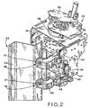
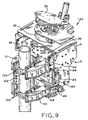
- modular vibratory side grip pile driver 30 is shown and generally includes housing 31, first assembly 35, and jaw assembly 50.
- Pile driver 30 may be used to grasp and drive sheet or beam, e.g., I-beam and H-beam, pile 33 into the ground.
- Housing 31 includes vibratory gear case 36 and mounting base 37.
- Bracket 41 connects housing 31 to attachment assembly 32 which is used to attach pile driver 30 to an excavator or other suitable construction machine for mounting pile driver 30 thereon.
- Rotational connector 38 is provided along with attachment plate 32 to permit rotation of housing 31 relative to the excavator.
- Pile driver 30 is a modification of the Model SPM 15 vibratory pile driver manufactured by Hercules Machinery Corporation of Fort Wayne, Indiana, and incorporates most of the mechanism of such pile driver except for the structure that adds the modularity feature. In other words, the base unit remains the same for the various configurations adapted to grip certain types of sheet, pipe, H or other pile.
- Mounting assembly 35 includes a mounting base 37 rigidly connected to the housing 31 and forming a first pair of jaw halves 37a and first gripping assembly 39.
- mounting base 37 having jaws 37a is stationary relative to gear case 36.
- mounting base 37 is movable relative to gear case 36.
- first gripping assembly 39 includes first gripping mount 53 which may include a plurality of slots 54 for mating engagement with a plurality of fasteners 55 for securing first gripping mount 53 to mounting base 37.
- First gripping assembly 39 also includes two contact plates 47 for providing direct contact with sheet pile 33.
- contact plates 47 have a knurled or otherwise roughened surface to enhance and facilitate gripping of sheet pile 33.
- Each contact plate 47 is assembled to first gripping mount 53 with rubber washer 46, bolt 43, spring 45, and nut 44. Spring 45 advantageously allows contact plate 47 to adjust during engagement of sheet pile 33.
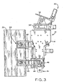
- jaw assembly 50 comprises a pair of jaws including first gripping assembly 39, arms 40, and arm gripping assemblies 52.
- Each arm 40 is pivotally and detachably affixed to housing 31 and preferably to an extension of mounting base 37 via pin 48 which creates a pivot joint of arm 40 relative to base 37.
- Each arm 40 is connected via pin 49 to hydraulic cylinder 42 which is connected to a hydraulic system (not shown) of the excavator to which pile driver 30 is attached to provide pivot control of arms 40.
- Each arm 40 includes an arm gripping assembly 52 detachably affixed thereto.
- Each arm gripping assembly 52 includes contact plate 47 which is connected to arm 40 via rubber washer 46, bolt 43, spring 45, and nut 44.
- pile driver 30 preferably includes lower jaws 51 which provide mating contact plates 47 for gripping a top portion of sheet pile 33 to facilitate final driving of pile 33 into the ground.
- jaw assembly 50 provides side-gripping force on pile 33 in which arms 40 are hydraulically actuated to grasp and move sheet pile 33 into a desired location for driving pile 33 into the ground.
- the upper and lower sets of jaw halves forming the jaws of jaw assembly 50 are open so that a pile 33 can enter the jaws laterally and then be gripped when the jaws 50 are closed.
- Arms 40 secure pile 33 while gear case 36 provides vibration while the excavator guides modular vibratory pile driver 30 towards the ground and sheet pile 33 into the ground.
- Modular vibratory pile driver 30 defines centerline 60 ( Fig. 4 ) along which the most focused and concentrated power is developed in pile driver 30.
- centerline 60 matches centerline 61 of sheet pile 33, thereby enhancing the efficiency of energy transfer to pile 33 and reducing stress on gear case 36.
- modular vibratory pile driver 30 facilitates substantially straight driving of pile 33 because centerline 60 matches centerline 61.
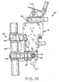
- modular vibratory pile driver configuration 130 is shown and is substantially identical to modular vibratory pile driver 30, described above with reference to Figs. 1-7 , except for arms 140, arm gripping assembly 152, and first gripping assembly 139, as described below that have been installed in place of arms 40 and gripping assemblies 52 and 39, respectively.
- housing 31 remains the same in the configuration shown in Figs. 8-11 as compared with the configuration shown in Figs. 1-7 .
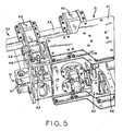
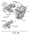
- modular vibratory side grip pile driver 130 configured as a cylindrical pile driver is shown and generally includes housing 31, assembly 135, and jaws 150. Pile driver 130 may be used to grasp and drive large pipe pile 133 into the ground or other desirable location.
- Mounting assembly 135 includes mounting base 37 and first gripping assembly 139.
- First gripping assembly 139 includes first gripping mount 153 detachably mounted to base 37.
- First gripping assembly 139 also includes two contact surfaces 147 for providing direct contact with pile 133.
- contact surfaces 147 are arcuate to match the outer diameter of pile 133 and are knurled to enhance and facilitate gripping of pile 133.
- Jaw assembly 150 includes mounting base 37, first gripping assembly 139, arms 140, and arm gripping assemblies 152.
- Each arm 140 is pivotally and detachably affixed to base 37 via pin 48 which creates a pivot joint of arm 140 relative to mounting base 37.
- Each arm 140 is connected via pin 49 to hydraulic cylinder 42 which is connected to a hydraulic system (not shown) of the excavator to which pile driver 130 is attached to provide pivot control of arms 140.
- Each arm 140 includes an arm gripping assembly 152 detachably affixed thereto.
- Arm gripping assembly 152 includes arm gripping mount 156 with contact surfaces 147 for providing direct contact with pile 133.
- contact surfaces 147 are arcuate to match an outer diameter of pile 133 and are knurled to enhance and facilitate gripping of pile 133.
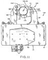
- Arm gripping assembly 152 and first gripping assembly 139 encircle pile 133 and form pipe grip engagement 157 therebetween, as shown in Fig. 11 .
- Pipe grip engagement 157 between arm gripping assembly 152 and first gripping assembly 139 prevents deformation of pile 133 when jaw assembly 150 is clamped shut and also enhances the hold of pile 133 in pile driver 130.
- pile driver configuration 130 may optionally include lower jaws 151 which provide mating contact surfaces 147 for gripping a top portion of pile 133 for final driving of pile 133 into the ground.
- jaw assembly 150 provides side gripping force on pile 133 in a substantially similar manner as jaw assembly 50; described above with respect to Figs. 1-7 .
- modular vibratory pile driver configuration 130 defines centerline 160 ( Fig. 11 ) which substantially matches centerline 161 of pile 133.
- a user of pile driver 30 removes pins 48, 49 associated with arms 40. Arms 40 are then removed from mounting base 37. Arms 140 may then be attached to mounting base 37 with pins 48, 49 to form configuration 130 which is now equipped to grip pile 133.
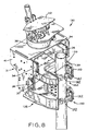
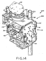
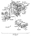
- modular vibratory pile driver configuration 230 is shown and is substantially identical to configurations 30, 130, described above with reference to Figs. 1-7 and 8-11 , except for arm gripping assembly 252 and first gripping assembly 239, as described below, i.e., all of the structure, including housing 31, remains the same in the configuration shown in Figs. 12-16 as compared with the configurations shown in Figs. 1-7 and 8-11 , and arms 140 remain the same in the configuration shown in Figs. 12-16 as compared with the configuration shown in Figs. 8-11 .
- Replacement gripping assemblies 235, 239, 250 and 252, gripping mounts 253 and 256 and contact services 247 are sized to match the smaller diameter cylindrical pipe pile 233.
- jaw assembly 250 provides side gripping force on pile 233 in a substantially similar manner as jaws 50, 150, described above with respect to Figs. 1-7 and 8-11 .
- modular vibratory pile driver 230 defines centerline 260 ( Fig. 16 ) which substantially matches centerline 261 of pile 233.
- first gripping assembly 139 and arm gripping assemblies 152 removes fasteners 155 from first gripping assembly 139 and arm gripping assemblies 152 to detach first gripping assembly 139 and arm gripping assemblies 152.
- First gripping assembly 239 and arm gripping assemblies 252 may then be respectively attached to mounting base 37 and arms 140 with fasteners 255, thereby forming configuration 230 which is equipped to grip smaller diameter pile 233.
- first gripping assembly 139 includes first gripping mount 153 which includes a plurality of slots 154 for mating engagement with a plurality of fasteners 155 for detachably affixing first gripping mount 153 to mounting base 37.
- Slots 154 are provided instead of holes or apertures sized to accept fasteners 155 because slots 154 allow first gripping mount 153 to move and slightly adjust front-to-back and side-to-side relative to base 37, thereby allowing first gripping mount 153 to align with arm gripping assembly 152 to securely hold pile 133.
- First gripping assembly 139 also may include two contact surfaces 147 for providing direct contact with pile 133.
- Piles 133, 233 may be formed as Schedule 40 piping having an outer diameter as small as approximately 1 ⁇ 2", 1", 11 ⁇ 2", 2", 3", 4", or 41 ⁇ 2", or as large as 40", 30", 20", 15", 10", 9", 8", 7", 65 ⁇ 8", 6", 51 ⁇ 2", or 5".
- modular vibratory pile driver configurations 30, 130, 230 provide flexibility and options depending on the type of pile to be driven into the ground.
- pile driver configuration 30 may be used to drive a sheet pile, e.g., sheet pile 33, into the ground.
- a user of pile driver 30 may want to drive a pipe pile.
- the user simply removes arms 40 from pile driver 30 and replaces them with arms 140 using the same attachments, i.e., pins 48, 49, to attach arms 140 to mounting base 37 and hydraulic cylinders 42 to form configuration 130.
- arms 140 have arm gripping assembly 152 detachably affixed thereto and mounting base 37 has complementary first gripping assembly 153 detachably affixed thereto to accommodate large pipe pile 133.
- arms 140 have arm gripping assemblies 252 detachably affixed thereto and base 37 has complementary first gripping assembly 253 detachably affixed thereto to accommodate small pipe pile 233. Therefore, arms 40, 140, arm gripping assemblies 152, 252, and first gripping assemblies 153, 253 are modular attachments that may be interchanged depending on the size and type of pile to be driven into the ground.
- the modular vibratory pile driver configuration described in the present application provide various degrees of modularity to provide variability and flexibility in selecting components to provide the optimum outcome for a desired pile driving procedure.
- the pivotable arms are replaced with a different set of pivotable arms.
- the arms remain attached to the first portion but the gripping assemblies are replaced with a different set of gripping assemblies.
- the modular vibratory pile driver configurations of the present application all utilize the same housing 31 including gear case 36 and mounting base 37.
- a user of the pile driver only needs to purchase a single base unit, instead of purchasing three or more separate pile drivers.
- the modular attachments of the present application are advantageously used interchangeably with the base unit to provide a modular side grip vibratory pile driver. Therefore, the overall cost of the pile driving system is substantially reduced. Moreover, the efficiency of the pile driving system is maintained.
Landscapes
- Engineering & Computer Science (AREA)
- Life Sciences & Earth Sciences (AREA)
- General Life Sciences & Earth Sciences (AREA)
- Mining & Mineral Resources (AREA)
- Paleontology (AREA)
- Civil Engineering (AREA)
- General Engineering & Computer Science (AREA)
- Structural Engineering (AREA)
- Placing Or Removing Of Piles Or Sheet Piles, Or Accessories Thereof (AREA)
- Measuring Volume Flow (AREA)
- Percussive Tools And Related Accessories (AREA)
Claims (11)
- Modulares Seitengriff-Vibrationsrammensystem (30), umfassend:ein Gehäuse (31), wobei das Gehäuse eine Trägerbasis (37) aufweist, die zwei erste Backenhälften (37a) umfasst;einen Vibrationsgetriebekasten (36), der auf dem Gehäuse (31) angebracht ist;eine Armanordnung, die zwei zweite Backenhälften (40) bildet, die mit dem Gehäuse verbunden sind, wobei die ersten und die zweiten Backenhälften jeweils ein Paar beabstandeter Backen bilden, die zum Ergreifen eines Rammguts (33) an zwei in Längsrichtung beabstandeten Stellen ausgelegt sind;eine Befestigungsanordnung (32), die zum Verbinden des Gehäuses (31) mit einer Baumaschine ausgelegt ist, wobei das Gehäuse mit der Befestigungsanordnung drehbar verbunden ist und zwischen einer ersten Position, in der die Backen (37a, 40) senkrecht angeordnet und waagrecht voneinander beabstandet sind, und einer zweiten Position, in der die Backen waagrecht angeordnet und senkrecht voneinander beabstandet sind, drehbar ist, gekennzeichnet durch:eine Vielzahl von Sätzen von Greifanordnungen (39, 139, 239), die unterschiedliche Greifprofile haben, die zum Greifen einer Auswahl unterschiedlicher Rammgutprofile angepasst sind, wobei die Sätze von Greifanordnungen (39, 139, 239) dazu ausgelegt sind, mit den Backen austauschbar verbunden zu sein und Rammgutgreifelemente der Backen zu bilden;wobei die Backen (37a, 40) einen einzelnen Satz der austauschbar verbundenen Greifanordnungen aufweisen, die mit jenen entfernbar und austauschbar verbunden sind;
wobei die Backen offen sind und einen Spalt bilden, so dass ein Rammgut (33) seitlich in die Backen eintreten kann. - Modulares Rammensystem nach Anspruch 1, dadurch gekennzeichnet, dass mindestens einige der Sätze von Greifanordnungen (39, 139, 239) eine erste Greifanordnung aufweisen, die auf der Trägerbasis (37) entfernbar angebracht ist.
- Modulares Rammensystem nach Anspruch 2, dadurch gekennzeichnet, dass die Greifanordnungen (39,139, 239) eine Vielzahl von Schlitzen (54) aufweisen, wobei die Schlitze dazu ausgelegt sind, das Hindurchführen von Befestigungselementen (55) zu ermöglichen, um die Greifanordnung auf der Trägerbasis (37) zu befestigen und um eine Einstellung der ersten Greifanordnung relativ zur Trägerbasis zu ermöglichen.
- Modulares Rammensystem nach Anspruch 2 oder Anspruch 3, dadurch gekennzeichnet, dass die mindestens einigen der Sätze von Greifanordnungen (39, 139, 239) Paare drehbarer Ersatzarme (40, 140) aufweisen, die mit den Armen austauschbar sind, die die zweiten Backenhälften bilden, wobei die Ersatzarme Greifprofile aufweisen, die mit entsprechenden ersten Greifanordnungen zusammenpassen.
- Modulares Rammensystem nach einem der vorhergehenden Ansprüche, dadurch gekennzeichnet, dass mindestens einige der Sätze von Greifanordnungen (39, 139, 239) eine zweite Greifanordnung (152) aufweisen, die entfernbar an der Armanordnung (140) angebracht ist.
- Modulares Rammensystem nach Anspruch 5, dadurch gekennzeichnet, dass die zweite Greifanordnung (152) eine Vielzahl von Schlitzen (154) aufweist, die dazu ausgelegt sind, das Hindurchführen von Befestigungselementen (155) zu ermöglichen, um die zweiteGreifanordnung an den Armen zu befestigen und um eine Einstellung der zweiten Greifanordnung relativ zu den Armen zu ermöglichen.
- Modulares Rammensystem nach einem der vorhergehenden Ansprüche, dadurch gekennzeichnet, dass die Sätze von Greifanordnungen (139, 239, 39) jeweils ausgelegt sind, ein relativ großes Rohr (133), eine relativ kleinesRohr (233), eine Stahlspundbohle (33) und einen Pfahl zu greifen.
- Modulares Rammensystem nach einem der vorhergehenden Ansprüche, dadurch gekennzeichnet, dass die zweiten Backenhälften (40) relativ zu den ersten Backenhälften (37a) von einer offenen Konfiguration in eine geschlossene Konfiguration beweglich sind, wobei die ersten Backenhälften (37a), wenn sie in der geschlossenen Konfiguration sind, mit den zweiten Backenhälften (40) in formschlüssigem Eingriff sind.
- Verfahren zum Umrüsten einer modularen Seitengriff-Vibrationsramme (30) von einer ersten Konfiguration in eine zweite Konfiguration, wobei das Verfahren umfasst:Vorsehen einer modularen Seitengriff-Vibrationsramme, die ein Gehäuse (31), einen Vibrationsgetriebekasten (36), der an dem Gehäuse angebracht ist, und ein Paar beabstandeter Backen (37a, 40) umfasst, wobei das Gehäuse drehbar mit einer Baumaschine verbunden ist und zwischen einer ersten Position, in der die Backen (37a, 40) senkrecht angeordnet und waagrecht voneinander beabstandet sind, und einer zweiten Position, in der die Backen waagrecht angeordnet und senkrecht voneinander beabstandet sind, drehbar ist, wobei die Backen offen sind und einen Spalt bilden, so dass ein Rammgut (33) seitlich in die Backen eintreten kann, wobei die Backen einen aktuellen Satz von Greifanordnungen (39) aufweisen, die Rammgutgreifflächen an den Backen vorsehen;Vorsehen einer Vielzahl von Sätzen von Greifanordnungen (39, 139, 239), die unterschiedliche Greifprofile haben, die zum Greifen einer Auswahl unterschiedlicher Rammgutprofile (33, 133, 233) angepasst sind; undAuswählen eines der Sätze von Greifanordnungen, der zu dem Profil eines zu rammenden Rammguts passt, und Austauschen des aktuellen Satzes von Greifanordnungen durch den ausgewählten Satz, um dadurch die Ramme zum Rammen eines Rammguts mit einem entsprechenden Profil zu konfigurieren.
- Verfahren nach Anspruch 9, dadurch gekennzeichnet, dass die Sätze von Greifanordnungen (139, 239, 39) jeweils ausgelegt sind, ein relativ großes Rohr (133), eine relativ kleines Rohr (233), eine Stahlspundbohle (33) und einen Pfahl zu greifen.
- Verfahren nach Anspruch 9 oder 10, dadurch gekennzeichnet, dass jede der Backen (37a, 40) eine stationäre Backenhälfte (37a) und eine entfernbare drehbare Backenhälfte (40) umfasst, und wobei der Schritt des Austauschens umfasst:Ersetzen aktueller drehbarer Backenhälften (40) durch drehbare Backenhälften (40, 140, 240) aus der Vielzahl von Sätzen, die ein Greifprofil haben, das zu dem Profil des zu rammenden Rammguts passt, und Ersetzen einer Greifanordnung an der stationären Backe (37a) durch eine Greifanordnung (39, 139, 239) aus der Vielzahl von Sätzen, die zu dem Profil des zu rammenden Rammguts passt.
Priority Applications (1)
| Application Number | Priority Date | Filing Date | Title |
|---|---|---|---|
| PL08009993T PL2003252T3 (pl) | 2007-06-14 | 2008-05-31 | Układ modułowego wibracyjnego kafara |
Applications Claiming Priority (2)
| Application Number | Priority Date | Filing Date | Title |
|---|---|---|---|
| US94397907P | 2007-06-14 | 2007-06-14 | |
| US12/041,133 US20080310923A1 (en) | 2007-06-14 | 2008-03-03 | Modular vibratory pile driver system |
Publications (3)
| Publication Number | Publication Date |
|---|---|
| EP2003252A1 EP2003252A1 (de) | 2008-12-17 |
| EP2003252B1 true EP2003252B1 (de) | 2009-12-09 |
| EP2003252B8 EP2003252B8 (de) | 2010-02-17 |
Family
ID=39671330
Family Applications (1)
| Application Number | Title | Priority Date | Filing Date |
|---|---|---|---|
| EP08009993A Active EP2003252B8 (de) | 2007-06-14 | 2008-05-31 | Vibrationsrammensystem |
Country Status (7)
| Country | Link |
|---|---|
| US (1) | US20080310923A1 (de) |
| EP (1) | EP2003252B8 (de) |
| AT (1) | ATE451503T1 (de) |
| CA (1) | CA2634402C (de) |
| DE (1) | DE602008000376D1 (de) |
| MX (1) | MX2008007656A (de) |
| PL (1) | PL2003252T3 (de) |
Cited By (3)
| Publication number | Priority date | Publication date | Assignee | Title |
|---|---|---|---|---|
| DE202018106039U1 (de) | 2018-10-22 | 2018-11-02 | Thyssenkrupp Ag | Vibrationsrammvorrichtung |
| US11708677B2 (en) | 2019-03-19 | 2023-07-25 | Sadikoglu Makine Insaat Metal Plastik Kagit San. Ve Tic. Ltd. Sti | Pile driving system |
| USD1101820S1 (en) | 2022-10-20 | 2025-11-11 | Movax Oy | Pile driver |
Families Citing this family (33)
| Publication number | Priority date | Publication date | Assignee | Title |
|---|---|---|---|---|
| TWI431637B (zh) * | 2007-05-22 | 2014-03-21 | Toshiba Kk | 圓筒狀結構物之預防保全、修補裝置以及預防保全、修補方法 |
| AU2008360042A1 (en) * | 2008-07-31 | 2010-02-04 | Yk Equipment Pte Ltd | A piling device |
| US8342778B2 (en) * | 2009-04-16 | 2013-01-01 | Hercules Machinery Corporation | Method and apparatus for facilitating the subterranean support of underground conduits having a fixed insertion axis |
| FI128958B (fi) * | 2009-04-17 | 2021-04-15 | Unisto Oy | Laitteisto paalujen ja ponttien iskemiseksi maaperään |
| US8096733B2 (en) * | 2009-07-10 | 2012-01-17 | Hercules Machinery Corporation | Apparatus for inserting sheet pile having an independently adjustable insertion axis and method for using the same |
| US8763719B2 (en) | 2010-01-06 | 2014-07-01 | American Piledriving Equipment, Inc. | Pile driving systems and methods employing preloaded drop hammer |
| FI20100104A0 (fi) | 2010-03-08 | 2010-03-08 | Unisto Oy | Paalujen maahan iskemiseen tarkoitettu laitteisto |
| US8434969B2 (en) * | 2010-04-02 | 2013-05-07 | American Piledriving Equipment, Inc. | Internal pipe clamp |
| PL2561143T3 (pl) * | 2010-04-19 | 2018-02-28 | Movax Oy | Urządzenie przeznaczone do wbijania pali w grunt |
| GB201112732D0 (en) * | 2011-07-25 | 2011-09-07 | Fast Frames Uk Ltd | Pile guide |
| WO2013110096A1 (en) * | 2012-01-19 | 2013-07-25 | Vo Thanh Minh | Piling apparatus and process for installation of pile assembly |
| FI124083B (fi) * | 2012-01-27 | 2014-03-14 | Movax Oy | Paalujen maahan iskemiseen tarkoitettu iskulaitteisto |
| US9249551B1 (en) | 2012-11-30 | 2016-02-02 | American Piledriving Equipment, Inc. | Concrete sheet pile clamp assemblies and methods and pile driving systems for concrete sheet piles |
| FR3001239B1 (fr) * | 2013-01-18 | 2015-02-06 | P T C | Appareil destine a l'extraction ou a l'enfoncement dans le sol d'un objet tel qu'un pieu ou un tube et procede correspondant |
| US9371624B2 (en) | 2013-07-05 | 2016-06-21 | American Piledriving Equipment, Inc. | Accessory connection systems and methods for use with helical piledriving systems |
| CN103485342B (zh) * | 2013-09-02 | 2015-10-21 | 太重(天津)滨海重型机械有限公司 | 多角度抱桩装置及液压打桩锤多作用试车台 |
| US10294624B2 (en) * | 2014-03-25 | 2019-05-21 | Les Produits Gilbert Inc. | Vibratory apparatus for forcing members into and out of a material |
| RU2677492C1 (ru) * | 2015-02-10 | 2019-01-17 | Айдин ОЗКАН | Соединительный адаптер |
| US20180195248A1 (en) * | 2015-07-29 | 2018-07-12 | Aydin Ozkan | A gripping machine |
| US10273646B2 (en) | 2015-12-14 | 2019-04-30 | American Piledriving Equipment, Inc. | Guide systems and methods for diesel hammers |
| GB201604833D0 (en) * | 2016-03-22 | 2016-05-04 | Vp Plc And Dale Mansfield Ltd | Improvements in and relating to tools |
| US10538892B2 (en) | 2016-06-30 | 2020-01-21 | American Piledriving Equipment, Inc. | Hydraulic impact hammer systems and methods |
| CN109024598B (zh) * | 2018-07-20 | 2020-08-28 | 浙江中星制针股份有限公司 | 一种各种板桩侧边夹持的打桩液压夹持锤 |
| WO2020080980A1 (en) * | 2018-10-16 | 2020-04-23 | Bruno Vedin | Apparatus for driving down and pulling up elongated objects into and from the ground or similar |
| CN109356166B (zh) * | 2018-11-06 | 2023-12-29 | 福建卓越建设工程开发有限公司 | 钢管桩-拉森钢板桩曲直结合打设组合支护体系及施工方法 |
| KR102185754B1 (ko) | 2020-07-16 | 2020-12-02 | 서원교 | 측면타입 바이브로 해머용 굴착기 결속장치 |
| US12129623B2 (en) | 2021-03-31 | 2024-10-29 | American Piledriving Equipment, Inc. | Segmented ram systems and methods for hydraulic impact hammers |
| GB2618092B (en) * | 2022-04-26 | 2024-12-11 | Dawson Const Plant Ltd | Side grip vibratory pile driver |
| EP4357534A1 (de) | 2022-10-20 | 2024-04-24 | Movax Oy | Pfahlvibrationssystem |
| KR20230002160A (ko) * | 2022-12-09 | 2023-01-05 | (주) 대동이엔지 | 정밀 수직시공 시스템을 가진 파일 드라이버 |
| US12606972B2 (en) | 2024-02-07 | 2026-04-21 | American Piledriving Equipment, Inc. | Variable moment vibratory systems and methods |
| USD1100996S1 (en) * | 2024-04-19 | 2025-11-04 | Movax Oy | Pile driver |
| WO2026064307A2 (en) * | 2024-09-19 | 2026-03-26 | Array Tech, Inc. | Pile installation confirmation instrument |
Family Cites Families (16)
| Publication number | Priority date | Publication date | Assignee | Title |
|---|---|---|---|---|
| JPS58143017A (ja) * | 1982-02-17 | 1983-08-25 | Takechi Koumushiyo:Kk | 鋼管体の押し込み引き抜き装置 |
| JPS57184129A (en) * | 1982-03-31 | 1982-11-12 | Junzo Mizobuchi | Vibration type pile-driving and drawing machine |
| GB2130997B (en) * | 1984-06-11 | 1985-09-18 | Joseph Samuel Neil | Vibration clamping device for use in supporting and placing sheeting when excavating |
| US4819740A (en) * | 1987-11-16 | 1989-04-11 | Vulcan Iron Works Inc. | Vibratory hammer/extractor |
| JPH04315609A (ja) * | 1991-01-24 | 1992-11-06 | Kenchiyou Kobe:Kk | 振動杭打機 |
| FI923880A0 (fi) * | 1991-09-30 | 1992-08-28 | Raunisto Airi | Slaganordning. |
| US5304015A (en) * | 1993-02-17 | 1994-04-19 | Sonomura Roy N | Pile grabber apparatus |
| US5355964A (en) * | 1993-07-12 | 1994-10-18 | White John L | Pile driving and/or pile pulling vibratory assembly with counterweights |
| US5609380B1 (en) * | 1994-11-15 | 2000-09-12 | American Piledriving Equipment Inc | Clamp assemblies for driving piles into the earth |
| US5549168A (en) * | 1995-02-06 | 1996-08-27 | Mgf Maschinen- Und Geraete-Fabrik Gmbh | Pile driving apparatus |
| US5653556A (en) * | 1995-10-10 | 1997-08-05 | American Piledriving Equipment, Inc. | Clamping apparatus and methods for driving caissons into the earth |
| JP3050523B2 (ja) * | 1996-04-25 | 2000-06-12 | 日本車輌製造株式会社 | チュービング装置用回転反力取り装置 |
| DE69738843D1 (de) * | 1996-10-07 | 2008-08-28 | Phd Inc | Greifer |
| US6447036B1 (en) * | 1999-03-23 | 2002-09-10 | American Piledriving Equipment, Inc. | Pile clamp systems and methods |
| GB2358035B (en) * | 1999-12-10 | 2004-02-25 | Aldridge Piling Equipment | Pile driving |
| CA2452448A1 (en) * | 2003-12-04 | 2005-06-04 | Joseph R.E. Nimens | Method and apparatus for installing a helical pile |
-
2008
- 2008-03-03 US US12/041,133 patent/US20080310923A1/en not_active Abandoned
- 2008-05-31 EP EP08009993A patent/EP2003252B8/de active Active
- 2008-05-31 PL PL08009993T patent/PL2003252T3/pl unknown
- 2008-05-31 DE DE602008000376T patent/DE602008000376D1/de active Active
- 2008-05-31 AT AT08009993T patent/ATE451503T1/de not_active IP Right Cessation
- 2008-06-06 CA CA2634402A patent/CA2634402C/en active Active
- 2008-06-12 MX MX2008007656A patent/MX2008007656A/es active IP Right Grant
Cited By (3)
| Publication number | Priority date | Publication date | Assignee | Title |
|---|---|---|---|---|
| DE202018106039U1 (de) | 2018-10-22 | 2018-11-02 | Thyssenkrupp Ag | Vibrationsrammvorrichtung |
| US11708677B2 (en) | 2019-03-19 | 2023-07-25 | Sadikoglu Makine Insaat Metal Plastik Kagit San. Ve Tic. Ltd. Sti | Pile driving system |
| USD1101820S1 (en) | 2022-10-20 | 2025-11-11 | Movax Oy | Pile driver |
Also Published As
| Publication number | Publication date |
|---|---|
| PL2003252T3 (pl) | 2010-07-30 |
| ATE451503T1 (de) | 2009-12-15 |
| MX2008007656A (es) | 2009-03-04 |
| DE602008000376D1 (de) | 2010-01-21 |
| CA2634402C (en) | 2012-02-07 |
| CA2634402A1 (en) | 2008-12-14 |
| EP2003252B8 (de) | 2010-02-17 |
| US20080310923A1 (en) | 2008-12-18 |
| EP2003252A1 (de) | 2008-12-17 |
Similar Documents
| Publication | Publication Date | Title |
|---|---|---|
| EP2003252B1 (de) | Vibrationsrammensystem | |
| EP0654106A1 (de) | Kupplungsvorrichtung für ein arbeitsgerät | |
| KR101196876B1 (ko) | 굴삭기용 어태치먼트의 회전 제어장치 | |
| JP3868046B2 (ja) | 壁鋸装置および該装置用の鋸板 | |
| EP1192318A1 (de) | Einrichtung zum rammen eines pfahles | |
| EP1983112B1 (de) | Vibrationsrüttler zum Niederbringen eines Pfahls oder eines Formrohres | |
| EP1105210B1 (de) | Verstellbarer exzenterschwinghammer | |
| WO2008114031A1 (en) | Improvements in and relating to pile driving | |
| US20080182738A1 (en) | Robotic end-of-arm tool quick-change device | |
| US20240133145A1 (en) | Pile driving system | |
| EP1844199A1 (de) | Schnellkupplungsvorrichtung für ein arbeitswerkzeug | |
| CN101808931A (zh) | 用于多种机械构型的通用铺管机框架 | |
| KR101018767B1 (ko) | 죠 크러셔 | |
| CN201792700U (zh) | 车轮装饰物安装工具 | |
| US6988433B2 (en) | Power-operated tool holder | |
| EP3942113B1 (de) | Neuartiges pfahlrammungssystem | |
| JP6997353B1 (ja) | 鋼製セグメントの製造方法 | |
| US20060191169A1 (en) | Arrangement for fixing an add-on piece e.g. an excavator shovel, to a boom of a shovel or a vehicle in a replaceable manner | |
| CN204935508U (zh) | 一种便携式电动阀门扳手 | |
| CN213944385U (zh) | 拉拔器及钣金凹坑修复系统 | |
| FI123633B (fi) | Rikotusvasara ja kiinnitysmenetelmä | |
| CN115138894B (zh) | 一种白车身点焊焊点拆除工具 | |
| KR100778275B1 (ko) | 강관 외면 용접 로봇의 자동주행장치 | |
| KR20190070014A (ko) | 기동장비 조향 핸들 탈거용 풀러 | |
| JPH07150586A (ja) | 作業機具の取付け装置 |
Legal Events
| Date | Code | Title | Description |
|---|---|---|---|
| PUAI | Public reference made under article 153(3) epc to a published international application that has entered the european phase |
Free format text: ORIGINAL CODE: 0009012 |
|
| AK | Designated contracting states |
Kind code of ref document: A1 Designated state(s): AT BE BG CH CY CZ DE DK EE ES FI FR GB GR HR HU IE IS IT LI LT LU LV MC MT NL NO PL PT RO SE SI SK TR |
|
| AX | Request for extension of the european patent |
Extension state: AL BA MK RS |
|
| 17P | Request for examination filed |
Effective date: 20090511 |
|
| GRAP | Despatch of communication of intention to grant a patent |
Free format text: ORIGINAL CODE: EPIDOSNIGR1 |
|
| AKX | Designation fees paid |
Designated state(s): AT BE BG CH CY CZ DE DK EE ES FI FR GB GR HR HU IE IS IT LI LT LU LV MC MT NL NO PL PT RO SE SI SK TR |
|
| GRAS | Grant fee paid |
Free format text: ORIGINAL CODE: EPIDOSNIGR3 |
|
| GRAA | (expected) grant |
Free format text: ORIGINAL CODE: 0009210 |
|
| AK | Designated contracting states |
Kind code of ref document: B1 Designated state(s): AT BE BG CH CY CZ DE DK EE ES FI FR GB GR HR HU IE IS IT LI LT LU LV MC MT NL NO PL PT RO SE SI SK TR |
|
| REG | Reference to a national code |
Ref country code: GB Ref legal event code: FG4D |
|
| REG | Reference to a national code |
Ref country code: CH Ref legal event code: EP |
|
| REG | Reference to a national code |
Ref country code: IE Ref legal event code: FG4D |
|
| RAP2 | Party data changed (patent owner data changed or rights of a patent transferred) |
Owner name: UNISTO OY LTD Owner name: HERCULES MACHINERY CORPORATION, |
|
| REF | Corresponds to: |
Ref document number: 602008000376 Country of ref document: DE Date of ref document: 20100121 Kind code of ref document: P |
|
| NLT2 | Nl: modifications (of names), taken from the european patent patent bulletin |
Owner name: HERCULES MACHINERY CORPORATION, EN UNISTO OY LTD Effective date: 20100120 |
|
| REG | Reference to a national code |
Ref country code: RO Ref legal event code: EPE |
|
| REG | Reference to a national code |
Ref country code: NL Ref legal event code: T3 |
|
| PG25 | Lapsed in a contracting state [announced via postgrant information from national office to epo] |
Ref country code: NO Free format text: LAPSE BECAUSE OF FAILURE TO SUBMIT A TRANSLATION OF THE DESCRIPTION OR TO PAY THE FEE WITHIN THE PRESCRIBED TIME-LIMIT Effective date: 20100309 Ref country code: SE Free format text: LAPSE BECAUSE OF FAILURE TO SUBMIT A TRANSLATION OF THE DESCRIPTION OR TO PAY THE FEE WITHIN THE PRESCRIBED TIME-LIMIT Effective date: 20091209 Ref country code: LT Free format text: LAPSE BECAUSE OF FAILURE TO SUBMIT A TRANSLATION OF THE DESCRIPTION OR TO PAY THE FEE WITHIN THE PRESCRIBED TIME-LIMIT Effective date: 20091209 |
|
| LTIE | Lt: invalidation of european patent or patent extension |
Effective date: 20091209 |
|
| PG25 | Lapsed in a contracting state [announced via postgrant information from national office to epo] |
Ref country code: LV Free format text: LAPSE BECAUSE OF FAILURE TO SUBMIT A TRANSLATION OF THE DESCRIPTION OR TO PAY THE FEE WITHIN THE PRESCRIBED TIME-LIMIT Effective date: 20091209 Ref country code: HR Free format text: LAPSE BECAUSE OF FAILURE TO SUBMIT A TRANSLATION OF THE DESCRIPTION OR TO PAY THE FEE WITHIN THE PRESCRIBED TIME-LIMIT Effective date: 20091209 Ref country code: SI Free format text: LAPSE BECAUSE OF FAILURE TO SUBMIT A TRANSLATION OF THE DESCRIPTION OR TO PAY THE FEE WITHIN THE PRESCRIBED TIME-LIMIT Effective date: 20091209 |
|
| PG25 | Lapsed in a contracting state [announced via postgrant information from national office to epo] |
Ref country code: AT Free format text: LAPSE BECAUSE OF FAILURE TO SUBMIT A TRANSLATION OF THE DESCRIPTION OR TO PAY THE FEE WITHIN THE PRESCRIBED TIME-LIMIT Effective date: 20091209 |
|
| PG25 | Lapsed in a contracting state [announced via postgrant information from national office to epo] |
Ref country code: BG Free format text: LAPSE BECAUSE OF FAILURE TO SUBMIT A TRANSLATION OF THE DESCRIPTION OR TO PAY THE FEE WITHIN THE PRESCRIBED TIME-LIMIT Effective date: 20100309 Ref country code: EE Free format text: LAPSE BECAUSE OF FAILURE TO SUBMIT A TRANSLATION OF THE DESCRIPTION OR TO PAY THE FEE WITHIN THE PRESCRIBED TIME-LIMIT Effective date: 20091209 Ref country code: IS Free format text: LAPSE BECAUSE OF FAILURE TO SUBMIT A TRANSLATION OF THE DESCRIPTION OR TO PAY THE FEE WITHIN THE PRESCRIBED TIME-LIMIT Effective date: 20100409 Ref country code: ES Free format text: LAPSE BECAUSE OF FAILURE TO SUBMIT A TRANSLATION OF THE DESCRIPTION OR TO PAY THE FEE WITHIN THE PRESCRIBED TIME-LIMIT Effective date: 20100320 |
|
| REG | Reference to a national code |
Ref country code: PL Ref legal event code: T3 |
|
| PG25 | Lapsed in a contracting state [announced via postgrant information from national office to epo] |
Ref country code: CZ Free format text: LAPSE BECAUSE OF FAILURE TO SUBMIT A TRANSLATION OF THE DESCRIPTION OR TO PAY THE FEE WITHIN THE PRESCRIBED TIME-LIMIT Effective date: 20091209 Ref country code: SK Free format text: LAPSE BECAUSE OF FAILURE TO SUBMIT A TRANSLATION OF THE DESCRIPTION OR TO PAY THE FEE WITHIN THE PRESCRIBED TIME-LIMIT Effective date: 20091209 Ref country code: BE Free format text: LAPSE BECAUSE OF FAILURE TO SUBMIT A TRANSLATION OF THE DESCRIPTION OR TO PAY THE FEE WITHIN THE PRESCRIBED TIME-LIMIT Effective date: 20091209 |
|
| PLBE | No opposition filed within time limit |
Free format text: ORIGINAL CODE: 0009261 |
|
| STAA | Information on the status of an ep patent application or granted ep patent |
Free format text: STATUS: NO OPPOSITION FILED WITHIN TIME LIMIT |
|
| PG25 | Lapsed in a contracting state [announced via postgrant information from national office to epo] |
Ref country code: GR Free format text: LAPSE BECAUSE OF FAILURE TO SUBMIT A TRANSLATION OF THE DESCRIPTION OR TO PAY THE FEE WITHIN THE PRESCRIBED TIME-LIMIT Effective date: 20100310 Ref country code: CY Free format text: LAPSE BECAUSE OF FAILURE TO SUBMIT A TRANSLATION OF THE DESCRIPTION OR TO PAY THE FEE WITHIN THE PRESCRIBED TIME-LIMIT Effective date: 20091209 |
|
| 26N | No opposition filed |
Effective date: 20100910 |
|
| PG25 | Lapsed in a contracting state [announced via postgrant information from national office to epo] |
Ref country code: MC Free format text: LAPSE BECAUSE OF NON-PAYMENT OF DUE FEES Effective date: 20100531 |
|
| PG25 | Lapsed in a contracting state [announced via postgrant information from national office to epo] |
Ref country code: DK Free format text: LAPSE BECAUSE OF FAILURE TO SUBMIT A TRANSLATION OF THE DESCRIPTION OR TO PAY THE FEE WITHIN THE PRESCRIBED TIME-LIMIT Effective date: 20091209 |
|
| PG25 | Lapsed in a contracting state [announced via postgrant information from national office to epo] |
Ref country code: IE Free format text: LAPSE BECAUSE OF NON-PAYMENT OF DUE FEES Effective date: 20100531 Ref country code: MT Free format text: LAPSE BECAUSE OF FAILURE TO SUBMIT A TRANSLATION OF THE DESCRIPTION OR TO PAY THE FEE WITHIN THE PRESCRIBED TIME-LIMIT Effective date: 20091209 |
|
| PG25 | Lapsed in a contracting state [announced via postgrant information from national office to epo] |
Ref country code: LU Free format text: LAPSE BECAUSE OF NON-PAYMENT OF DUE FEES Effective date: 20100531 Ref country code: HU Free format text: LAPSE BECAUSE OF FAILURE TO SUBMIT A TRANSLATION OF THE DESCRIPTION OR TO PAY THE FEE WITHIN THE PRESCRIBED TIME-LIMIT Effective date: 20100610 Ref country code: PT Free format text: LAPSE BECAUSE OF FAILURE TO SUBMIT A TRANSLATION OF THE DESCRIPTION OR TO PAY THE FEE WITHIN THE PRESCRIBED TIME-LIMIT Effective date: 20100509 |
|
| REG | Reference to a national code |
Ref country code: CH Ref legal event code: PL |
|
| PG25 | Lapsed in a contracting state [announced via postgrant information from national office to epo] |
Ref country code: CH Free format text: LAPSE BECAUSE OF NON-PAYMENT OF DUE FEES Effective date: 20120531 Ref country code: LI Free format text: LAPSE BECAUSE OF NON-PAYMENT OF DUE FEES Effective date: 20120531 |
|
| REG | Reference to a national code |
Ref country code: FR Ref legal event code: PLFP Year of fee payment: 9 |
|
| REG | Reference to a national code |
Ref country code: FR Ref legal event code: PLFP Year of fee payment: 10 |
|
| REG | Reference to a national code |
Ref country code: FR Ref legal event code: PLFP Year of fee payment: 11 |
|
| PGFP | Annual fee paid to national office [announced via postgrant information from national office to epo] |
Ref country code: RO Payment date: 20230515 Year of fee payment: 16 |
|
| PGFP | Annual fee paid to national office [announced via postgrant information from national office to epo] |
Ref country code: TR Payment date: 20230518 Year of fee payment: 16 |
|
| PG25 | Lapsed in a contracting state [announced via postgrant information from national office to epo] |
Ref country code: RO Free format text: LAPSE BECAUSE OF NON-PAYMENT OF DUE FEES Effective date: 20240531 |
|
| PG25 | Lapsed in a contracting state [announced via postgrant information from national office to epo] |
Ref country code: RO Free format text: LAPSE BECAUSE OF NON-PAYMENT OF DUE FEES Effective date: 20240531 |
|
| PGFP | Annual fee paid to national office [announced via postgrant information from national office to epo] |
Ref country code: NL Payment date: 20250526 Year of fee payment: 18 |
|
| PGFP | Annual fee paid to national office [announced via postgrant information from national office to epo] |
Ref country code: FI Payment date: 20250526 Year of fee payment: 18 |
|
| PGFP | Annual fee paid to national office [announced via postgrant information from national office to epo] |
Ref country code: PL Payment date: 20250527 Year of fee payment: 18 Ref country code: DE Payment date: 20250528 Year of fee payment: 18 |
|
| PGFP | Annual fee paid to national office [announced via postgrant information from national office to epo] |
Ref country code: GB Payment date: 20250527 Year of fee payment: 18 |
|
| PGFP | Annual fee paid to national office [announced via postgrant information from national office to epo] |
Ref country code: IT Payment date: 20250528 Year of fee payment: 18 |
|
| PGFP | Annual fee paid to national office [announced via postgrant information from national office to epo] |
Ref country code: FR Payment date: 20250527 Year of fee payment: 18 |