EP2003015A2 - Accoudoir latéral réglable - Google Patents
Accoudoir latéral réglable Download PDFInfo
- Publication number
- EP2003015A2 EP2003015A2 EP08001477A EP08001477A EP2003015A2 EP 2003015 A2 EP2003015 A2 EP 2003015A2 EP 08001477 A EP08001477 A EP 08001477A EP 08001477 A EP08001477 A EP 08001477A EP 2003015 A2 EP2003015 A2 EP 2003015A2
- Authority
- EP
- European Patent Office
- Prior art keywords
- armrest according
- armrest
- door
- guide
- screw
- Prior art date
- Legal status (The legal status is an assumption and is not a legal conclusion. Google has not performed a legal analysis and makes no representation as to the accuracy of the status listed.)
- Withdrawn
Links
- 230000008878 coupling Effects 0.000 claims description 2
- 238000010168 coupling process Methods 0.000 claims description 2
- 238000005859 coupling reaction Methods 0.000 claims description 2
- 230000002093 peripheral effect Effects 0.000 claims description 2
- 230000002349 favourable effect Effects 0.000 description 3
- 238000009434 installation Methods 0.000 description 3
- 230000033001 locomotion Effects 0.000 description 3
- 238000005452 bending Methods 0.000 description 2
- 230000008901 benefit Effects 0.000 description 2
- 230000008859 change Effects 0.000 description 1
- 230000000295 complement effect Effects 0.000 description 1
- 238000011161 development Methods 0.000 description 1
- 230000018109 developmental process Effects 0.000 description 1
- 230000003993 interaction Effects 0.000 description 1
- 239000002184 metal Substances 0.000 description 1
- 230000004048 modification Effects 0.000 description 1
- 238000012986 modification Methods 0.000 description 1
Images

Classifications
-
- B—PERFORMING OPERATIONS; TRANSPORTING
- B60—VEHICLES IN GENERAL
- B60N—SEATS SPECIALLY ADAPTED FOR VEHICLES; VEHICLE PASSENGER ACCOMMODATION NOT OTHERWISE PROVIDED FOR
- B60N2/00—Seats specially adapted for vehicles; Arrangement or mounting of seats in vehicles
- B60N2/75—Arm-rests
- B60N2/763—Arm-rests adjustable
- B60N2/77—Height adjustment
-
- B—PERFORMING OPERATIONS; TRANSPORTING
- B60—VEHICLES IN GENERAL
- B60N—SEATS SPECIALLY ADAPTED FOR VEHICLES; VEHICLE PASSENGER ACCOMMODATION NOT OTHERWISE PROVIDED FOR
- B60N2/00—Seats specially adapted for vehicles; Arrangement or mounting of seats in vehicles
- B60N2/75—Arm-rests
- B60N2/78—Arm-rests post or panel mounted
Definitions
- the front side doors of cars are usually equipped with armrests, which are mounted on the passenger compartment side facing the interior trim.
- the armrests are fixed to the side panel, so they can bring comfortable arm support only for people with the appropriate body size. People who are much taller or much smaller can not use the side armrest.
- the new side armrest for motor vehicles has an Armauflagepolster, which is located next to the inside of the door.
- the guide arrangement is designed such that the Armauflagepolster next to the inside of the door in height is adjustable.
- a housing arrangement is provided, which is arranged outside of the door body and adjacent to the inner lining. On the housing assembly, the Armauflagepolster is attached.
- the side armrest can be adjusted manually or electrically. In the latter case, it is advantageous if a self-locking drive device is provided, with which the guide arrangement can be adjusted.
- the guide assembly may be composed of a base or base part and a movable relative to the base or base portion.
- the base part is fixed to the supporting parts of the door body, to which he optionally projects with corresponding arms or tabs through openings in the inner lining.
- a self-locking drive can be formed by one or more screw spindles.
- Another possibility for a guide arrangement is the use of at least one guide column on which a slider is slidably guided.
- the direction of movement which is predetermined by the guide columns or the screw spindles, not exactly vertical but slightly inclined inclined.
- the armrest cushion shifts in the height adjustment simultaneously in the direction parallel to the vehicle longitudinal to be brought into the most favorable position.
- the in the side armrest with housed control switch for example, for the windows and the like, can thus also be moved and remain in the ergonomic position.
- they can also be rigidly housed on the inside of the door in a separate housing.
- the screw spindles are suitably coupled kinematically with each other, which is sufficient to provide only a drive motor.
- the kinematic coupling of the screw spindles with each other and with the drive motor can take place via toothed belts.
- the housing assembly may be in the shape of a bowl or cup, the bottom of which faces the interior of the passenger compartment while the rim forms or supports the armrest cushion.
- Another possibility is to use a two-part housing arrangement, with one part firmly attached the door panel sits and forms an open-topped pipe. This tube is telescopically overlapped by another downward pointing tube. On the second tube, the Armauflagepolster is attached.
- the latter possibility has the advantage that no upwardly open gaps are created through which parts can fall into the interior.
- the Armauflagepolster be arranged with a certain gap separated from the inner lining, which helps to avoid grinding marks on the inside of the door panel.
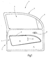
- Fig. 1 shows in a plan view the inside of a driver's door 1, which is composed as main components of a body 2 and a window frame 3 stretched over the body.
- the window frame 3 encloses a window opening 4 with an unrecognizable window pane located therein.
- an insert plate 5 is fixed to the outside in a known manner, the rearview mirror.
- the body 2 is provided to the passenger compartment with a door trim 6.
- a side armrest assembly 7 In front of the inner lining 6 is a side armrest assembly 7. Further, a door opening handle 8 can be seen.
- the side armrest assembly 7 includes an armrest housing 9, which forms or carries an armrest pad 11 on the upper side.
- the armrest housing 9 is adjustable in the vertical direction according to the double arrow 12 in order to adjust the height of the Armauflage pad 11 to a comfortable attitude can.
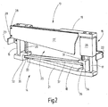
- Fig. 2 shows a hidden from the housing 9 guide assembly 13, as used to guide the housing assembly 9 to accomplish the height adjustment.
- the guide assembly 13 also carries a drive means 14, with which the electrical height adjustment is made possible.
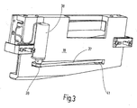
- Fig. 3 illustrates the guide assembly 13 with respect to the door 3 facing back.
- the guide assembly 13 includes a base member 15 and two anchored to the base member 15 guide columns 16, 17, which are spaced along the base member 15 from each other. When assembled, the guide post 17 is near the rear end while the post 16 is located near the front end.
- Both guide columns 16, 17 are parallel to one another and define the direction of movement along which the housing 9 is adjustable.
- the base part 15 has a substantially flat base plate 18 which stands upright. At the upper end, a bar 19 projecting towards the observer is provided and at the lower end of which a bar 21 projecting towards the observer is provided.
- Attached to the base plate 18 are further fasteners 22, 23 which may be used to secure the base plate 18 to supporting elements of the door 1, for example, to beams that project through the inner lining 6 into the interior of the housing 9.
- the guide assembly 13 further comprises a carriage 25 provided with two sliders, of which the slider 26 is visible in the broken part.
- the two sliders 26 run on the respective associated guide column 16, 17, for which they include corresponding through holes.
- the two sliders 26 of the carriage 25 are interconnected by a connecting plate 27, which is welded, for example, with the sliders 26 or made in one piece with these.
- the slider 26 is shown simplified as a cuboid. It is understood that he is provided to save weight with a corresponding rib structure.
- the housing 9 is screwed, including in the connecting plate 27 mounting holes 28 are provided, which are formed in tabs with which the connecting plate 27 protrudes forward and backward over the two sliders 26.
- the drive device 14 includes in the embodiment shown two screw spindles 29 and 31, which are arranged axially parallel to the guide columns 16, 17 and, as shown, are adjacent.
- the threaded spindle 29 is rotatably mounted in the lower bar 21 and held there axially immovable.
- the bar 21 includes a structure with a pocket-like recess 32 which is open at 33 in the direction of the other screw 31.
- the threaded spindle 29 passes through a threaded hole which is contained axially parallel to the bore for the guide column 16 in the relevant slider.
- the threaded spindle 31 which is located next to the guide column 17, is mounted in a U-shaped bearing block 34, which opens in the direction of the slot-like opening 33. With the threaded spindle 31 corresponds to a corresponding threaded hole in the slider 26th
- a geared motor 38 is provided in addition to the threaded spindle 31, whose longitudinal axis is aligned parallel to the axes of the guide columns 17.
- the geared motor 38 carries on its output shaft another toothed belt pulley 39 around which the toothed belt 37 also rotates. Since the drive motor 38 at the back or outside of the base plate 18 is provided, the base plate 18 for the passage of the toothed belt, a slot-like opening 41, as shown in the figure.
- the slit-like opening starts in the vicinity of the toothed pulley 35 and extends to the outer peripheral surface of the toothed pulley 36, so that the toothed belt 37 can pass without stripping.
- the toothed belt 37 forms approximately a right-angled triangle, wherein the right-angled tip is located at the toothed belt pulley 37 of the drive motor 38. This configuration results from the position of the geared motor 38 next to the screw 31.
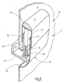
- the installation position of the guide assembly 13 with the drive assembly 14 results from the representation of Fig. 4 , Thereafter, the guide assembly 13 sits next to the inside facing inside of the inner lining 6, wherein the plate 27 of the carriage 25 to the interior shows.
- the guide columns 16 and 17 and the threaded spindles 29 and 31 extend between the plate 27 of the carriage 25 and a defined by the interior of the adjacent surface of the inner panel 6 level.
- the housing 9 is cup-shaped or cup-shaped with a base 45 and a self-contained circumferential collar or edge 46.
- the base or bottom surface 45 is approximately parallel to the inner lining 6 and is spaced therefrom according to the height of the rim 46.
- the height of the rim 46 corresponds to the space occupied by the guide device 13 in the direction of the depth, measured perpendicular to the surface of the inner lining 6.
- FIG. 4 shows, attached to the plate 27 of the carriage 25 housing shell 9 in the vicinity of the rear end and in the vicinity of the front end by a respective guide column 16, 17 and simultaneously guided in the axial direction by the immediately adjacent threaded spindles 29 and 31 in vertical Direction supported.
- the upper portion of the collar or rim 46 may be padded in a known manner to form the armrest pad 11 in a corresponding longitudinal section.
- a recessed grip 47 may be formed, which is used in a known manner to use the door for the purpose of closing. This force is also introduced via the housing shell on the guide device 13 and from there on to the supporting structure of the door 1.
- the entire drive means 13 is housed in the housing shell of the side armrest assembly 7, it is necessarily located largely outside of the door body 2, which is bounded by the inner lining 6 and the outer metal skin.
- the guide device 13 and the drive device 14 do not require installation space within the door body 2.
- the open side of the housing shell 9 is facing the inner panel 6 and the housing shell 9 runs at the height adjustment as a whole next to the inner panel 6 up and down.
- the housing assembly 9 in the embodiment according to Fig. 5 is in two parts. It is composed of a stationary lower part 50 and a movable upper part 51, which carries the Armauflagepolster 11.
- the lower housing part 50 forms an upwardly open pipe section 52, for example, with a rectangular plan.
- the upwardly open pipe section 51 is overlapped by the cup-like upper housing part 51 telescopically outside.
- the upper housing part 51 has an upwardly facing bottom 53 and a circumferential collar or rim 54, which runs around the pipe section 52 on the outside in the mounted state.
- the pipe section 52 is spaced on the side adjacent to the inner lining 6, creating a gap 55 in which the corresponding part of the collar or rim 54 can run with play.
- the lower housing part 50 merges into a cavity, which, as shown, covers an opening 56 in the inner lining 6. Through the opening 56, the base part 15, which is screwed in accordance with the structure of the door 1 runs.
- the screw shaft 31 rotates in a threaded sleeve 37, which points from the downwardly facing surface of the cup bottom 53 in the downward direction.
- the threaded sleeve 37 is anchored according to kinking and tilting.
- the stiffening elements for this purpose are not shown in the drawing for reasons of clarity.
- a side armrest for motor vehicles has a guide device with which the Armauflagepolster is substantially adjustable in the vertical direction.
- a drive device is integrated, with which the height adjustment is accomplished by an electric motor.
- the drive device and the guide device sit outside of the door body in a housing shell, which forms the arm support area in sections at the same time.
Landscapes
- Engineering & Computer Science (AREA)
- Aviation & Aerospace Engineering (AREA)
- Transportation (AREA)
- Mechanical Engineering (AREA)
- Passenger Equipment (AREA)
- Seats For Vehicles (AREA)
- Power-Operated Mechanisms For Wings (AREA)
Applications Claiming Priority (1)
| Application Number | Priority Date | Filing Date | Title |
|---|---|---|---|
| DE102007027611A DE102007027611A1 (de) | 2007-06-12 | 2007-06-12 | Verstellbare Seitenarmlehne |
Publications (2)
| Publication Number | Publication Date |
|---|---|
| EP2003015A2 true EP2003015A2 (fr) | 2008-12-17 |
| EP2003015A3 EP2003015A3 (fr) | 2009-08-19 |
Family
ID=39805545
Family Applications (1)
| Application Number | Title | Priority Date | Filing Date |
|---|---|---|---|
| EP08001477A Withdrawn EP2003015A3 (fr) | 2007-06-12 | 2008-01-26 | Accoudoir latéral réglable |
Country Status (3)
| Country | Link |
|---|---|
| EP (1) | EP2003015A3 (fr) |
| JP (1) | JP2008308163A (fr) |
| DE (1) | DE102007027611A1 (fr) |
Cited By (3)
| Publication number | Priority date | Publication date | Assignee | Title |
|---|---|---|---|---|
| EP3243696A1 (fr) * | 2016-05-13 | 2017-11-15 | Grammer Ag | Accoudoir |
| US20200180481A1 (en) * | 2018-12-10 | 2020-06-11 | GM Global Technology Operations LLC | Dynamic adjustable armrest |
| FR3127452A1 (fr) * | 2021-09-30 | 2023-03-31 | Faurecia Interieur Industrie | Ensemble pour un intérieur de véhicule comprenant au moins un accoudoir et intérieur de véhicule comprenant un tel ensemble |
Families Citing this family (1)
| Publication number | Priority date | Publication date | Assignee | Title |
|---|---|---|---|---|
| US11110838B2 (en) * | 2019-11-27 | 2021-09-07 | Kiekert Ag | Armrest for a motor vehicle |
Family Cites Families (9)
| Publication number | Priority date | Publication date | Assignee | Title |
|---|---|---|---|---|
| DE3930270A1 (de) * | 1989-09-11 | 1991-03-21 | Happich Gmbh Gebr | Armlehne insbesondere fuer fahrzeuge |
| FR2716651B1 (fr) * | 1994-02-28 | 1996-05-15 | Peugeot | Accoudoir perfectionné réglable en hauteur pour véhicule automobile. |
| DE10104077A1 (de) * | 2001-01-29 | 2002-08-01 | Brose Fahrzeugteile | Verstellmechanismus für eine Armlehne einer Kraftfahrzeugtür |
| DE10060857A1 (de) * | 2000-12-06 | 2002-06-13 | Brose Fahrzeugteile | Verstellmechanismus für eine Armlehne einer Kraftfahrzeugtür |
| JP2004520125A (ja) * | 2001-01-29 | 2004-07-08 | ブローゼ・ファールツォイクタイレ・ゲーエムベーハー・ウント・コンパニ・コマンディットゲゼルシャフト・コーブルク | 自動車ドア用のアームレストサブアセンブリ |
| DE10144485A1 (de) * | 2001-09-10 | 2003-03-27 | Brose Fahrzeugteile | Verstellbare Armauflage für eine Kraftfahrzeugtür |
| DE20107992U1 (de) * | 2001-05-11 | 2001-07-26 | Seeber Creative Center AG & Co. KG, 85221 Dachau | Fahrzeugtür mit Armauflage |
| DE102004026928B4 (de) * | 2004-06-01 | 2011-05-05 | Johnson Controls Interiors Gmbh & Co. Kg | Verstellbare Armlehne |
| DE102005052526A1 (de) * | 2005-11-03 | 2007-05-10 | Lear Corp., Southfield | Einstellbare Fahrzeug-Armlehne |
-
2007
- 2007-06-12 DE DE102007027611A patent/DE102007027611A1/de not_active Withdrawn
-
2008
- 2008-01-26 EP EP08001477A patent/EP2003015A3/fr not_active Withdrawn
- 2008-06-11 JP JP2008153339A patent/JP2008308163A/ja active Pending
Non-Patent Citations (1)
| Title |
|---|
| None |
Cited By (5)
| Publication number | Priority date | Publication date | Assignee | Title |
|---|---|---|---|---|
| EP3243696A1 (fr) * | 2016-05-13 | 2017-11-15 | Grammer Ag | Accoudoir |
| US20200180481A1 (en) * | 2018-12-10 | 2020-06-11 | GM Global Technology Operations LLC | Dynamic adjustable armrest |
| US10759316B2 (en) * | 2018-12-10 | 2020-09-01 | GM Global Technology Operations LLC | Dynamic adjustable armrest |
| FR3127452A1 (fr) * | 2021-09-30 | 2023-03-31 | Faurecia Interieur Industrie | Ensemble pour un intérieur de véhicule comprenant au moins un accoudoir et intérieur de véhicule comprenant un tel ensemble |
| US12214705B2 (en) | 2021-09-30 | 2025-02-04 | Faurecia Interieur Industrie | Assembly for a vehicle interior comprising at least one armrest and vehicle interior comprising such an assembly |
Also Published As
| Publication number | Publication date |
|---|---|
| JP2008308163A (ja) | 2008-12-25 |
| DE102007027611A1 (de) | 2008-12-18 |
| EP2003015A3 (fr) | 2009-08-19 |
Similar Documents
| Publication | Publication Date | Title |
|---|---|---|
| DE69126303T2 (de) | Kraftfahrzeugsitz für behinderte | |
| DE68902427T2 (de) | Motorisch verstellbare armlehne. | |
| DE10036441B4 (de) | Kopfstütze für einen Fahrzeugsitz | |
| EP1339565B1 (fr) | Mecanisme de reglage en hauteur d'un accoudoir d'une portiere de vehicule automobile | |
| DE4009127C2 (de) | Kopfstützenanordnung | |
| EP2473372B1 (fr) | Siège de véhicule, notamment siège de véhicule utilitaire | |
| DE102006056651A1 (de) | Mittelarmlehne mit Parallelverstellungsmöglichkeiten | |
| DE69101409T2 (de) | Zentralisierte Steuervorrichtung für Fahrzeugsitze. | |
| DE10331612B4 (de) | Kopfstütze | |
| EP1355801B1 (fr) | Sous-ensemble d'accoudoir destine a une portiere automobile | |
| EP2003015A2 (fr) | Accoudoir latéral réglable | |
| DE10358478A1 (de) | Fluggastsitz | |
| DE10029926C2 (de) | Armlehne für einen Kraftfahrzeugsitz | |
| DE2856695A1 (de) | Einstellbares stuetzteil an einem fahrzeugsitz | |
| DE4114252A1 (de) | Rollstuhl mit sitzhubeinrichtung | |
| DE102014219091A1 (de) | Anordnung einer Ablagefläche und zweier Sitze in einem Fahrzeug | |
| EP3573862B1 (fr) | Automobile | |
| EP1256484A1 (fr) | Porte de véhicule avec accoudoir | |
| DE10120167C1 (de) | Verstellbarer Fahrzeugsitz | |
| DE102007027608A1 (de) | Höhenverstellbare Armlehne für Kraftfahrzeuge | |
| DE202007015598U1 (de) | Verstellbare Seitenarmlehne | |
| DE10060857A1 (de) | Verstellmechanismus für eine Armlehne einer Kraftfahrzeugtür | |
| DE3732150A1 (de) | Arbeitstisch, insbesondere buerotisch mit einer hoehen- und neigungsverstelleinrichtung | |
| EP1762423B1 (fr) | Véhicule automobile avec un siège | |
| DE19830701A1 (de) | Verstellbare Fußstütze, insbesondere für ein Kraftfahrzeug |
Legal Events
| Date | Code | Title | Description |
|---|---|---|---|
| PUAI | Public reference made under article 153(3) epc to a published international application that has entered the european phase |
Free format text: ORIGINAL CODE: 0009012 |
|
| AK | Designated contracting states |
Kind code of ref document: A2 Designated state(s): AT BE BG CH CY CZ DE DK EE ES FI FR GB GR HR HU IE IS IT LI LT LU LV MC MT NL NO PL PT RO SE SI SK TR |
|
| AX | Request for extension of the european patent |
Extension state: AL BA MK RS |
|
| PUAL | Search report despatched |
Free format text: ORIGINAL CODE: 0009013 |
|
| AK | Designated contracting states |
Kind code of ref document: A3 Designated state(s): AT BE BG CH CY CZ DE DK EE ES FI FR GB GR HR HU IE IS IT LI LT LU LV MC MT NL NO PL PT RO SE SI SK TR |
|
| AX | Request for extension of the european patent |
Extension state: AL BA MK RS |
|
| AKX | Designation fees paid | ||
| STAA | Information on the status of an ep patent application or granted ep patent |
Free format text: STATUS: THE APPLICATION IS DEEMED TO BE WITHDRAWN |
|
| 18D | Application deemed to be withdrawn |
Effective date: 20100220 |
|
| REG | Reference to a national code |
Ref country code: DE Ref legal event code: 8566 |