EP2003015A2 - Adjustable side armrest - Google Patents
Adjustable side armrest Download PDFInfo
- Publication number
- EP2003015A2 EP2003015A2 EP08001477A EP08001477A EP2003015A2 EP 2003015 A2 EP2003015 A2 EP 2003015A2 EP 08001477 A EP08001477 A EP 08001477A EP 08001477 A EP08001477 A EP 08001477A EP 2003015 A2 EP2003015 A2 EP 2003015A2
- Authority
- EP
- European Patent Office
- Prior art keywords
- armrest according
- armrest
- door
- guide
- screw
- Prior art date
- Legal status (The legal status is an assumption and is not a legal conclusion. Google has not performed a legal analysis and makes no representation as to the accuracy of the status listed.)
- Withdrawn
Links
Images

Classifications
-
- B—PERFORMING OPERATIONS; TRANSPORTING
- B60—VEHICLES IN GENERAL
- B60N—SEATS SPECIALLY ADAPTED FOR VEHICLES; VEHICLE PASSENGER ACCOMMODATION NOT OTHERWISE PROVIDED FOR
- B60N2/00—Seats specially adapted for vehicles; Arrangement or mounting of seats in vehicles
- B60N2/75—Arm-rests
- B60N2/763—Arm-rests adjustable
- B60N2/77—Height adjustment
-
- B—PERFORMING OPERATIONS; TRANSPORTING
- B60—VEHICLES IN GENERAL
- B60N—SEATS SPECIALLY ADAPTED FOR VEHICLES; VEHICLE PASSENGER ACCOMMODATION NOT OTHERWISE PROVIDED FOR
- B60N2/00—Seats specially adapted for vehicles; Arrangement or mounting of seats in vehicles
- B60N2/75—Arm-rests
- B60N2/78—Arm-rests post or panel mounted
Definitions
- the front side doors of cars are usually equipped with armrests, which are mounted on the passenger compartment side facing the interior trim.
- the armrests are fixed to the side panel, so they can bring comfortable arm support only for people with the appropriate body size. People who are much taller or much smaller can not use the side armrest.
- the new side armrest for motor vehicles has an Armauflagepolster, which is located next to the inside of the door.
- the guide arrangement is designed such that the Armauflagepolster next to the inside of the door in height is adjustable.
- a housing arrangement is provided, which is arranged outside of the door body and adjacent to the inner lining. On the housing assembly, the Armauflagepolster is attached.
- the side armrest can be adjusted manually or electrically. In the latter case, it is advantageous if a self-locking drive device is provided, with which the guide arrangement can be adjusted.
- the guide assembly may be composed of a base or base part and a movable relative to the base or base portion.
- the base part is fixed to the supporting parts of the door body, to which he optionally projects with corresponding arms or tabs through openings in the inner lining.
- a self-locking drive can be formed by one or more screw spindles.
- Another possibility for a guide arrangement is the use of at least one guide column on which a slider is slidably guided.
- the direction of movement which is predetermined by the guide columns or the screw spindles, not exactly vertical but slightly inclined inclined.
- the armrest cushion shifts in the height adjustment simultaneously in the direction parallel to the vehicle longitudinal to be brought into the most favorable position.
- the in the side armrest with housed control switch for example, for the windows and the like, can thus also be moved and remain in the ergonomic position.
- they can also be rigidly housed on the inside of the door in a separate housing.
- the screw spindles are suitably coupled kinematically with each other, which is sufficient to provide only a drive motor.
- the kinematic coupling of the screw spindles with each other and with the drive motor can take place via toothed belts.
- the housing assembly may be in the shape of a bowl or cup, the bottom of which faces the interior of the passenger compartment while the rim forms or supports the armrest cushion.
- Another possibility is to use a two-part housing arrangement, with one part firmly attached the door panel sits and forms an open-topped pipe. This tube is telescopically overlapped by another downward pointing tube. On the second tube, the Armauflagepolster is attached.
- the latter possibility has the advantage that no upwardly open gaps are created through which parts can fall into the interior.
- the Armauflagepolster be arranged with a certain gap separated from the inner lining, which helps to avoid grinding marks on the inside of the door panel.
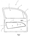
- Fig. 1 shows in a plan view the inside of a driver's door 1, which is composed as main components of a body 2 and a window frame 3 stretched over the body.
- the window frame 3 encloses a window opening 4 with an unrecognizable window pane located therein.
- an insert plate 5 is fixed to the outside in a known manner, the rearview mirror.
- the body 2 is provided to the passenger compartment with a door trim 6.
- a side armrest assembly 7 In front of the inner lining 6 is a side armrest assembly 7. Further, a door opening handle 8 can be seen.
- the side armrest assembly 7 includes an armrest housing 9, which forms or carries an armrest pad 11 on the upper side.
- the armrest housing 9 is adjustable in the vertical direction according to the double arrow 12 in order to adjust the height of the Armauflage pad 11 to a comfortable attitude can.
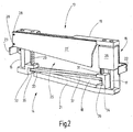
- Fig. 2 shows a hidden from the housing 9 guide assembly 13, as used to guide the housing assembly 9 to accomplish the height adjustment.
- the guide assembly 13 also carries a drive means 14, with which the electrical height adjustment is made possible.
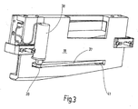
- Fig. 3 illustrates the guide assembly 13 with respect to the door 3 facing back.
- the guide assembly 13 includes a base member 15 and two anchored to the base member 15 guide columns 16, 17, which are spaced along the base member 15 from each other. When assembled, the guide post 17 is near the rear end while the post 16 is located near the front end.
- Both guide columns 16, 17 are parallel to one another and define the direction of movement along which the housing 9 is adjustable.
- the base part 15 has a substantially flat base plate 18 which stands upright. At the upper end, a bar 19 projecting towards the observer is provided and at the lower end of which a bar 21 projecting towards the observer is provided.
- Attached to the base plate 18 are further fasteners 22, 23 which may be used to secure the base plate 18 to supporting elements of the door 1, for example, to beams that project through the inner lining 6 into the interior of the housing 9.
- the guide assembly 13 further comprises a carriage 25 provided with two sliders, of which the slider 26 is visible in the broken part.
- the two sliders 26 run on the respective associated guide column 16, 17, for which they include corresponding through holes.
- the two sliders 26 of the carriage 25 are interconnected by a connecting plate 27, which is welded, for example, with the sliders 26 or made in one piece with these.
- the slider 26 is shown simplified as a cuboid. It is understood that he is provided to save weight with a corresponding rib structure.
- the housing 9 is screwed, including in the connecting plate 27 mounting holes 28 are provided, which are formed in tabs with which the connecting plate 27 protrudes forward and backward over the two sliders 26.
- the drive device 14 includes in the embodiment shown two screw spindles 29 and 31, which are arranged axially parallel to the guide columns 16, 17 and, as shown, are adjacent.
- the threaded spindle 29 is rotatably mounted in the lower bar 21 and held there axially immovable.
- the bar 21 includes a structure with a pocket-like recess 32 which is open at 33 in the direction of the other screw 31.
- the threaded spindle 29 passes through a threaded hole which is contained axially parallel to the bore for the guide column 16 in the relevant slider.
- the threaded spindle 31 which is located next to the guide column 17, is mounted in a U-shaped bearing block 34, which opens in the direction of the slot-like opening 33. With the threaded spindle 31 corresponds to a corresponding threaded hole in the slider 26th
- a geared motor 38 is provided in addition to the threaded spindle 31, whose longitudinal axis is aligned parallel to the axes of the guide columns 17.
- the geared motor 38 carries on its output shaft another toothed belt pulley 39 around which the toothed belt 37 also rotates. Since the drive motor 38 at the back or outside of the base plate 18 is provided, the base plate 18 for the passage of the toothed belt, a slot-like opening 41, as shown in the figure.
- the slit-like opening starts in the vicinity of the toothed pulley 35 and extends to the outer peripheral surface of the toothed pulley 36, so that the toothed belt 37 can pass without stripping.
- the toothed belt 37 forms approximately a right-angled triangle, wherein the right-angled tip is located at the toothed belt pulley 37 of the drive motor 38. This configuration results from the position of the geared motor 38 next to the screw 31.
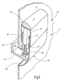
- the installation position of the guide assembly 13 with the drive assembly 14 results from the representation of Fig. 4 , Thereafter, the guide assembly 13 sits next to the inside facing inside of the inner lining 6, wherein the plate 27 of the carriage 25 to the interior shows.
- the guide columns 16 and 17 and the threaded spindles 29 and 31 extend between the plate 27 of the carriage 25 and a defined by the interior of the adjacent surface of the inner panel 6 level.
- the housing 9 is cup-shaped or cup-shaped with a base 45 and a self-contained circumferential collar or edge 46.
- the base or bottom surface 45 is approximately parallel to the inner lining 6 and is spaced therefrom according to the height of the rim 46.
- the height of the rim 46 corresponds to the space occupied by the guide device 13 in the direction of the depth, measured perpendicular to the surface of the inner lining 6.
- FIG. 4 shows, attached to the plate 27 of the carriage 25 housing shell 9 in the vicinity of the rear end and in the vicinity of the front end by a respective guide column 16, 17 and simultaneously guided in the axial direction by the immediately adjacent threaded spindles 29 and 31 in vertical Direction supported.
- the upper portion of the collar or rim 46 may be padded in a known manner to form the armrest pad 11 in a corresponding longitudinal section.
- a recessed grip 47 may be formed, which is used in a known manner to use the door for the purpose of closing. This force is also introduced via the housing shell on the guide device 13 and from there on to the supporting structure of the door 1.
- the entire drive means 13 is housed in the housing shell of the side armrest assembly 7, it is necessarily located largely outside of the door body 2, which is bounded by the inner lining 6 and the outer metal skin.
- the guide device 13 and the drive device 14 do not require installation space within the door body 2.
- the open side of the housing shell 9 is facing the inner panel 6 and the housing shell 9 runs at the height adjustment as a whole next to the inner panel 6 up and down.
- the housing assembly 9 in the embodiment according to Fig. 5 is in two parts. It is composed of a stationary lower part 50 and a movable upper part 51, which carries the Armauflagepolster 11.
- the lower housing part 50 forms an upwardly open pipe section 52, for example, with a rectangular plan.
- the upwardly open pipe section 51 is overlapped by the cup-like upper housing part 51 telescopically outside.
- the upper housing part 51 has an upwardly facing bottom 53 and a circumferential collar or rim 54, which runs around the pipe section 52 on the outside in the mounted state.
- the pipe section 52 is spaced on the side adjacent to the inner lining 6, creating a gap 55 in which the corresponding part of the collar or rim 54 can run with play.
- the lower housing part 50 merges into a cavity, which, as shown, covers an opening 56 in the inner lining 6. Through the opening 56, the base part 15, which is screwed in accordance with the structure of the door 1 runs.
- the screw shaft 31 rotates in a threaded sleeve 37, which points from the downwardly facing surface of the cup bottom 53 in the downward direction.
- the threaded sleeve 37 is anchored according to kinking and tilting.
- the stiffening elements for this purpose are not shown in the drawing for reasons of clarity.
- a side armrest for motor vehicles has a guide device with which the Armauflagepolster is substantially adjustable in the vertical direction.
- a drive device is integrated, with which the height adjustment is accomplished by an electric motor.
- the drive device and the guide device sit outside of the door body in a housing shell, which forms the arm support area in sections at the same time.
Abstract
Description
Die vorderen Seitentüren von PKWs sind üblicherweise mit Armlehnen ausgestattet, die auf der dem Fahrgastraum zugekehrten Seite der Innenverkleidung angebracht sind. Die Armlehnen sind an der Seitenverkleidung fix, womit sie nur für Personen mit der passenden Körpergröße eine komfortable Armunterstützung bringen können. Menschen, die viel größer oder viel kleiner sind, können die Seitenarmlehne nicht benutzen.The front side doors of cars are usually equipped with armrests, which are mounted on the passenger compartment side facing the interior trim. The armrests are fixed to the side panel, so they can bring comfortable arm support only for people with the appropriate body size. People who are much taller or much smaller can not use the side armrest.
Ausgehend hiervon ist es Aufgabe der Erfindung eine höhenverstellbare Seitenarmlehne zu schaffen.Based on this, it is an object of the invention to provide a height-adjustable side armrest.
Diese Aufgabe wird erfindungsgemäß durch eine Seitenarmlehne mit den Merkmalen des Anspruches 1 gelöst.This object is achieved by a side armrest with the features of
Die neue Seitenarmelehne für Kraftfahrzeuge weist ein Armauflagepolster auf, das neben der Innenseite der Tür angeordnet ist. Es ist wenigstens eine Führungsanordnung vorhanden, die das Armauflagepolster mit den tragenden Teilen der Fahrzeugtür oder der Innenseite verbindet. Die Führungsanordnung ist derart ausgeführt, dass das Armauflagepolster neben der Innenseite der Tür in der Höhe verstellbar ist.The new side armrest for motor vehicles has an Armauflagepolster, which is located next to the inside of the door. There is at least one guide arrangement which connects the armrest pad to the supporting parts of the vehicle door or the inside. The guide arrangement is designed such that the Armauflagepolster next to the inside of the door in height is adjustable.
Zum Verkleiden der Führungsanordnung ist eine Gehäuseanordnung vorgesehen, die außerhalb des Türkorpus und neben der Innenverkleidung angeordnet ist. An der Gehäuseanordnung ist das Armauflagepolster befestigt.For disguising the guide arrangement, a housing arrangement is provided, which is arranged outside of the door body and adjacent to the inner lining. On the housing assembly, the Armauflagepolster is attached.
Dadurch wird erreicht, dass mit dem Verstellen des Armauflagepolsters sich auch die Lage der Gehäuseanordnung an der Innenseite der Tür verändert. Ein weiterer Vorteil besteht darin, dass die Führungsanordnung außerhalb des Türkorpus angeordnet werden kann, indem sie letztlich innerhalb der Seitenarmlehne untergebracht wird. Dadurch wird der notorische Platzmangel, der im Inneren des Türkorpus herrscht, umgangen.This ensures that with the adjustment of the Armauflage pad also changes the position of the housing assembly on the inside of the door. Another advantage is that the guide assembly can be placed outside the door body by ultimately being housed within the side armrest. This bypasses the notorious lack of space that prevails inside the door carcass.
Die Seitenarmlehne kann manuell oder elektrisch verstellt werden. Im letzteren Falle ist es von Vorteil, wenn eine selbsthemmende Antriebseinrichtung vorgesehen ist, mit der die Führungsanordnung verstellt werden kann.The side armrest can be adjusted manually or electrically. In the latter case, it is advantageous if a self-locking drive device is provided, with which the guide arrangement can be adjusted.
Die Führungsanordnung kann sich aus einem Sockel- oder Basisteil und einem gegenüber dem Sockel- oder Basisteil beweglichen Abschnitt zusammensetzen. Zweckmäßigerweise ist der Sockelteil an den tragenden Teilen des Türkorpus befestigt, wozu er gegebenfalls mit entsprechenden Auslegern oder Laschen durch Öffnungen in der Innenverkleidung hindurch ragt.The guide assembly may be composed of a base or base part and a movable relative to the base or base portion. Conveniently, the base part is fixed to the supporting parts of the door body, to which he optionally projects with corresponding arms or tabs through openings in the inner lining.
Ein selbsthemmender Antrieb kann von einer oder mehreren Schraubspindeln gebildet sein.A self-locking drive can be formed by one or more screw spindles.
Eine einfache Ausführung ergibt sich, wenn die Schraubspindeln selbst gleichzeitig als Führungseinrichtung dienen, die die Kippmomente in den Türkorpus einleiten, wenn das Armauflagepolster mit einer Druckkraft beaufschlagt wird.A simple embodiment results when the screw spindles themselves serve as guide means which initiate the tilting moments in the door body when the Armauflagepolster is subjected to a compressive force.
Eine andere Möglichkeit für eine Führungsanordnung besteht in der Verwendung wenigstens einer Führungssäule, auf der ein Gleiter gleitend geführt ist.Another possibility for a guide arrangement is the use of at least one guide column on which a slider is slidably guided.
Aus ergonomischen Gründen kann es zweckmäßig sein, wenn die Bewegungsrichtung, die durch die Führungssäulen oder die Schraubspindeln vorgegeben ist, nicht exakt vertikal sondern leicht schräg geneigt verläuft. Dadurch verschiebt sich das Armauflagepolster bei der Höhenverstellung gleichzeitig in Richtung parallel zur Fahrzeuglängsache um in die jeweils günstigste Position gebracht zu werden. Die in der Seitenarmlehne mit untergebrachten Steuerschalter, beispielsweise für die Fensterheber und dergleichen, können damit ebenfalls mitbewegt werden und bleiben in der ergonomisch günstigen Position. Sie können jedoch auch starr an der Innenseite der Tür in einem getrennten Gehäuse untergebracht sein.For ergonomic reasons, it may be expedient if the direction of movement, which is predetermined by the guide columns or the screw spindles, not exactly vertical but slightly inclined inclined. As a result, the armrest cushion shifts in the height adjustment simultaneously in the direction parallel to the vehicle longitudinal to be brought into the most favorable position. The in the side armrest with housed control switch, for example, for the windows and the like, can thus also be moved and remain in the ergonomic position. However, they can also be rigidly housed on the inside of the door in a separate housing.
Günstige Kräfteverhältnisse ergeben sich, wenn zwei Schraubspindeln verwendet werden, von denen die eine in der Nähe des vorderen Endes und die andere in der Nähe des hinteren Endes des Armauflagepolsters bzw. der Seitenarmlehne angeordnet ist.Favorable power relationships arise when two screw spindles are used, one of which is located near the front end and the other in the vicinity of the rear end of the Armauflagepolster or the side armrest.
Die Schraubspindeln sind zweckmäßigerweise kinematisch miteinander gekuppelt, womit es genügt, lediglich einen Antriebsmotor vorzusehen. Die kinematische Kupplung der Schraubspindeln untereinander und mit dem Antriebsmotor kann über Zahnriemen erfolgen.The screw spindles are suitably coupled kinematically with each other, which is sufficient to provide only a drive motor. The kinematic coupling of the screw spindles with each other and with the drive motor can take place via toothed belts.
Die Gehäuseanordnung kann die Gestalt einer Schale oder eines Bechers haben, deren/dessen Boden zu dem Inneren des Fahrgastraums zeigt, während der Rand das Armauflagepolster bildet oder ein solches trägt.The housing assembly may be in the shape of a bowl or cup, the bottom of which faces the interior of the passenger compartment while the rim forms or supports the armrest cushion.
Eine andere Möglichkeit besteht darin, eine zweiteilige Gehäuseanordnung zu verwenden, wobei ein Teil fest an der Türverkleidung sitzt und ein nach oben offenes Rohr bildet. Dieses Rohr wird von einem weiteren nach unten zeigenden Rohr teleskopartig übergriffen. An dem zweiten Rohr ist das Armauflagepolster befestigt. Die letztgenannte Möglichkeit hat den Vorteil, dass keine nach oben offenen Spalte entstehen, durch die Teile in das Innere fallen können. Außerdem kann so das Armauflagepolster mit einem gewissen Spalt von der Innenverkleidung getrennt angeordnet werden, was hilft, Schleifspuren auf der Innenseite der Türverkleidung zu vermeiden.Another possibility is to use a two-part housing arrangement, with one part firmly attached the door panel sits and forms an open-topped pipe. This tube is telescopically overlapped by another downward pointing tube. On the second tube, the Armauflagepolster is attached. The latter possibility has the advantage that no upwardly open gaps are created through which parts can fall into the interior. In addition, so the Armauflagepolster be arranged with a certain gap separated from the inner lining, which helps to avoid grinding marks on the inside of the door panel.
Im Übrigen sind Weiterbildungen der Erfindung Gegenstand von Unteransprüchen.Incidentally, developments of the invention are the subject of subclaims.
Die nachfolgende Figurenbeschreibung erläutert Aspekte zum Verständnis der Erfindung. Weitere, nicht beschriebene Details kann der Fachmann in der gewohnten Weise den Zeichnungen entnehmen, die insoweit die Figurenbeschreibung ergänzen. Es ist klar, dass eine Reihe von Abwandlungen möglich sind.The following description of the figures explains aspects for understanding the invention. Further, not described details, the expert can refer to the drawings in the usual way, the extent to complement the description of the figures. It is clear that a number of modifications are possible.
Die nachfolgenden Zeichnungen sind nicht unbedingt maßstäblich. Zur Veranschaulichung von Details können möglicherweise bestimmte Bereiche übertrieben groß dargestellt sein. Darüber hinaus sind die Zeichnungen plakativ vereinfacht und enthalten nicht jedes bei der praktischen Ausführung gegebenenfalls vorhandene Detail. Die Begriffe "oben" und "unten" bzw. "vorne" und "hinten" beziehen sich auf die normale Einbaulage bzw. die Terminologie bei Kraftfahrzeugen.
- Fig. 1
- zeigt eine vordere linke Seitentür in einer Draufsicht auf die Innenseite.
- Fig. 2
- veranschaulicht in einer perspektivischen Darstellung die Führungs- und die Antriebseinrichtung der Seitenarmlehne in einer perspektivischen Darstellung, mit Blick von der Fahrzeuginnenseite her.
- Fig. 3
- zeigt die Anordnung nach
Fig. 2 in einer Blickrichtung aus der Sicht des Türkorpus. - Fig. 4
- veranschaulicht das Zusammenwirken der Führungs- und Antriebseinrichtung mit einer Gehäuseanordnung in einer perspektivischen, teilweise aufgebrochenen Darstellung.
- Fig. 5
- stellt eine andere Ausführungsform der Gehäuseanordnung mit einem teleskopischen oberen Teil dar, der das Armauflagepolster trägt.
- Fig. 1
- shows a front left side door in a plan view of the inside.
- Fig. 2
- illustrated in a perspective view of the guide and the drive means of the side armrest in a perspective view, viewed from the vehicle interior side.
- Fig. 3
- shows the arrangement after
Fig. 2 in a viewing direction from the perspective of the door carcass. - Fig. 4
- illustrates the interaction of the guiding and driving device with a housing arrangement in a perspective, partially broken-away view.
- Fig. 5
- Figure 5 illustrates another embodiment of the housing assembly with a telescopic upper portion supporting the armrest pad.
Der Korpus 2 ist zum Fahrgastinnenraum hin mit einer Türverkleidung 6 versehen. Vor der Innenverkleidung 6 befindet sich eine Seitenarmlehnenanordnung 7. Ferner ist ein Türöffnungsgriff 8 zu erkennen.The
Zu der Seitenarmlehnenanordnung 7 gehört ein Armlehnengehäuse 9, das auf der Oberseite ein Armlehnenpolster 11 bildet oder trägt. Das Armlehnengehäuse 9 ist in vertikaler Richtung entsprechend dem Doppelpfeil 12 verstellbar, um die Höhe des Armauflagepolsters 11 an eine bequeme Haltung anpassen zu können.To the
Es ist klar, dass die veranschaulichte Anordnung in der gleichen Weise auch bei der Beifahrertür oder an den hinteren Seitentüren getroffen werden kann. Die Fahrertür ist insoweit lediglich beispielhaft.It is clear that the illustrated arrangement can be made in the same way also in the passenger door or at the rear side doors. The driver's door is merely exemplary in this respect.
Die Führungsanordnung 13 trägt ferner eine Antriebseinrichtung 14, mit der die elektrische Höhenverstellung ermöglicht wird.The
Zu der Führungsanordnung 13 gehören ein Basisteil 15 sowie zwei an dem Basisteil 15 verankerte Führungssäulen 16, 17, die längs des Basisteils 15 voneinander beabstandet sind. Im montierten Zustand befindet sich die Führungssäule 17 in der Nähe des hinteren Endes während die Säule 16 in der Nähe des vorderen Endes angeordnet ist.The
Beide Führungssäulen 16, 17 sind zueinander achsparallel und definieren die Bewegungsrichtung, längs derer das Gehäuse 9 verstellbar ist.Both guide
Zur Befestigung der Säulen 16, 17 weist das Basisteil 15 eine im Wesentlichen ebene Grundplatte 18 auf, die aufrecht steht. An dem oberen Ende ist eine auf den Betrachter zu auskragende Leiste 19 und an deren unterem Ende eine auf den Betrachter zu auskragende Leiste 21 vorgesehen sind.For fixing the
Die beiden Führungssäulen 16, 17 stecken in entsprechenden Bohrungen in den Leisten 19, 21.The two
An der Grundplatte 18 sind ferner Befestigungselemente 22, 23 angebracht, die dazu verwendet werden können, die Grundplatte 18 an tragenden Elementen der Tür 1 zu befestigen, beispielsweise an Trägern, die durch die Innenverkleidung 6 hindurch in den Innenraum des Gehäuses 9 vorstehen.Attached to the
Die Führungsanordnung 13 umfasst ferner einen Schlitten 25, der mit zwei Gleitern versehen ist, von denen der Gleiter 26 in dem aufgebrochenen Teil sichtbar ist. Die beiden Gleiter 26 laufen auf der jeweils zugehörigen Führungssäule 16, 17, wozu sie entsprechende Durchgangsbohrungen enthalten.The
Die beiden Gleiter 26 des Schlittens 25 sind durch eine Verbindungsplatte 27 miteinander verbunden, die beispielsweise mit den Gleitern 26 verschweißt ist oder mit diesen einstückig hergestellt ist.The two
Der Gleiter 26 ist vereinfacht als Quader gezeigt. Es versteht sich, dass er zur Gewichtsersparnis mit einer entsprechenden Rippenstruktur versehen ist.The
An der Verbindungsplatte 27 ist das Gehäuse 9 festgeschraubt, wozu in der Verbindungsplatte 27 Befestigungsöffnungen 28 vorhanden sind, die in Laschen ausgebildet sind, mit denen die Verbindungsplatte 27 nach vorne und nach hinten über die beiden Gleiter 26 übersteht.At the connecting
Die Antriebseinrichtung 14 enthält bei dem gezeigten Ausführungsbeispiel zwei Schraubspindeln 29 und 31, die achsparallel zu den Führungssäulen 16, 17 angeordnet sind und, wie gezeigt, benachbart sind. Die Gewindespindel 29 ist drehbar in der unteren Leiste 21 gelagert und dort auch axial unverschieblich gehalten. Hierzu enthält die Leiste 21 einen Aufbau mit einer taschenartige Ausnehmung 32, die in Richtung auf die andere Schraubspindel 31 bei 33 offen ist. Die Gewindespindel 29 führt durch eine Gewindebohrung, die achsparallel zu der Bohrung für die Führungssäule 16 in dem betreffenden Gleiter enthalten ist.The
Die Gewindespindel 31, die sich neben der Führungssäule 17 befindet, ist in einem U-förmigen Lagerbock 34 gelagert, der sich in Richtung auf die schlitzartige Öffnung 33 öffnet. Mit der Gewindespindel 31 korrespondiert eine entsprechende Gewindebohrung in dem Gleiter 26.The threaded
Sowohl auf der Gewindespindel 29 als auch auf der Gewindespindel 31 sitzen unten auf gleicher Höhe drehfest Zahnriemenscheiben 35 und 36, die von einem gemeinsamen endlosen Zahnriemen 37 angetrieben sind.Both on the threaded
Auf der Rückseite der Grundplatte 18 ist neben der Gewindespindel 31 ein Getriebemotor 38 vorgesehen, dessen Längsachse parallel zu den Achsen der Führungssäulen 17 ausgerichtet ist. Der Getriebemotor 38 trägt auf seiner Ausgangswelle eine weitere Zahnriemenscheibe 39, um die der Zahnriemen 37 ebenfalls umläuft. Da der Antriebsmotor 38 an der Rückseite bzw. Außenseite der Grundplatte 18 vorgesehen ist, enthält die Grundplatte 18 zum Durchtritt des Zahnriemens eine schlitzartige Öffnung 41, wie dies in der Figur veranschaulicht ist. Die schlitzartige Öffnung beginnt in der Nähe der Zahnriemenscheibe 35 und reicht bis zur Außenumfangsfläche der Zahnriemenscheibe 36, so dass der Zahnriemen 37 ohne zu streifen hindurchtreten kann.On the back of the
In der Draufsicht bildet der Zahnriemen 37 etwa ein rechtwinkliges Dreieck, wobei die rechtwinklige Spitze bei der Zahnriemenscheibe 37 des Antriebsmotors 38 liegt. Diese Konfiguration ergibt sich aus Lage des Getriebemotors 38 neben der Schraubspindel 31.In the plan view, the
Die Einbaulage der Führungsanordnung 13 mit der Antriebsanordnung 14 ergibt sich aus der Darstellung von
Lediglich der auf der Rückseite der Grundplatte 18 aufbauende Getriebemotor 38 ragt in den Innenraum des Türkorpus 2 hinein.Only the geared
Das Gehäuse 9 ist becher- oder schalenartig gestaltet mit einer Grundfläche 45 und einem in sich geschlossenen umlaufenden Kragen oder Rand 46. Die Grund- oder Bodenfläche 45 liegt etwa parallel zu der Innenverkleidung 6 und ist von dieser entsprechend der Höhe des Randes 46 beabstandet. Die Höhe des Randes 46 entspricht dem Platz, den die Führungseinrichtung 13 in Richtung der Tiefe, gemessen senkrecht zu der Fläche der Innenverkleidung 6, beansprucht.The
Wie sich aus der Darstellung von
Der obere Bereich des Kragens oder Randes 46 kann in bekannter Weise gepolstert sein, um das Armauflagepolster 11 in einem entsprechenden Längsabschnitt zu bilden. Außerdem kann dort benachbart auch eine Griffmulde 47 ausgebildet sein, die in bekannter Weise benutzt wird, um die Tür zwecks Schließens heranzuziehen. Diese Kraft wird ebenfalls über die Gehäuseschale auf die Führungseinrichtung 13 und von dort weiter auf die tragende Struktur der Tür 1 eingeleitet.The upper portion of the collar or
Die Funktionsweise ist wie folgt:The operation is as follows:
Wenn der Benutzer die Höhe der Armauflagefläche 11 verändern will, setzt er durch einen Tastschalter den Getriebemotor 38 in Gang. Hierdurch wird der Zahnriemen 37 angetrieben, der synchron beide Schraubspindeln 29 und 31 antreibt. Je nach Drehrichtung wandert der Schlitten 25 entweder noch oben oder nach unten, je nachdem, ob der Benutzer die Armlehne weiter oben oder weiter unten haben möchte. Beim Erreichen der gewünschten Position lässt der Benutzer den Tastschalter los, womit die Antriebseinrichtung 14 stehen bleibt. Die Anordnung aus den Schraubspindeln 29, 31 mit den Gleitern 26 und dem Getriebemotor 38 ist selbsthemmend in dem Sinne, dass die einmal auf elektrischem Wege eingestellte Höhenposition auch erhalten bleibt, wenn sich der Benutzer mit Kraft auf das Armauflagepolster 11 stützt.When the user wants to change the height of the
Da die gesamte Antriebseinrichtung 13 in der Gehäuseschale der Seitenarmlehnenanordnung 7 untergebracht ist, befindet sie sich zwangsläufig weitgehend außerhalb des Türkorpus 2, der von der Innenverkleidung 6 und der äußeren Blechhaut begrenzt ist. Die Führungseinrichtung 13 sowie die Antriebseinrichtung 14 erfordern keinen Bauraum innerhalb des Türkorpus 2.Since the entire drive means 13 is housed in the housing shell of the
Wegen der Verwendung zweier voneinander beanstandete Schraubspindel 29 und 31, die im Übrigen in einer Ebene liegen, die auch die Achsen der Führungssäulen 16 und 17 enthält und die im Übrigen parallel zu der Innenseite der Innenverkleidung 6 verläuft, ist eine günstige Unterstützung erreicht.Because of the use of two spaced apart screwed
Die offene Seite der Gehäuseschale 9 ist der Innenverkleidung 6 zugekehrt und die Gehäuseschale 9 läuft bei der Höhenverstellung als Ganzes neben der Innenverkleidung 6 nach oben und nach unten.The open side of the
Wenn dies unerwünscht ist, beispielsweise deswegen weil sich der Spalt zwischen dem Rand 46 und der Innenverkleidung 6 schlecht abdichten lässt, kann die Anordnung nach
Die Gehäuseanordnung 9 bei dem Ausführungsbeispiel nach
Der Rohrabschnitt 52 ist auf der der Innenverkleidung 6 benachbarten Seite im Abstand angeordnet, wodurch ein Spalt 55 entsteht, in dem mit Spiel der entsprechende Teil des Kragens oder Randes 54 laufen kann.The
Im unteren Bereich geht das Gehäuseunterteil 50 in einen Hohlraum über, der, wie gezeigt, eine Öffnung 56 in der Innenverkleidung 6 überdeckt. Durch die Öffnung 56 läuft das Sockelteil 15, das entsprechend Struktur der Tür 1 festgeschraubt ist.In the lower region, the
Abweichend von dem vorherigen Ausführungsbeispiel, bei dem eine separater Schlitten 25 vorgesehen ist, der zusätzlich über Führungssäulen 16, 17 geführt ist, übernimmt bei dem Ausführungsbeispiel nach
Die Schraubspindel 31 dreht sich in einer Gewindehülse 37, die von der nach unten zeigenden Fläche des Becherbodens 53 in Richtung nach unten zeigt. Die Gewindehülse 37 ist entsprechend knick- und kippsteif verankert. Die Versteifungselemente hierfür sind in der Zeichnung aus Übersichtlichkeitsgründen nicht dargestellt.The
Ebenso ist die untere Lagerung der Gewindespindel 31 nicht im Einzelnen veranschaulicht. Es versteht sich für den Fachmann, dass diese Lagerung hinreichend steif ausgeführt sein muss, damit die Biegemomente, die über die Schraubspindel 31 von dem Gehäuseoberteil 51 her eingeleitet werden können, ohne nennenswerte Verbiegung der Schraubspindel 31 in dir tragende Struktur der Tür 1 eingeleitet werden können.Likewise, the lower bearing of the threaded
Eine Seitenarmlehne für Kraftfahrzeuge weist eine Führungseinrichtung auf, mit der das Armauflagepolster im Wesentlichen in vertikaler Richtung verstellbar ist. In der Führungseinrichtung ist eine Antriebseinrichtung integriert, mit der die Höhenverstellung elektromotorisch bewerkstelligt wird. Die Antriebseinrichtung und die Führungseinrichtung sitzen außerhalb des Türkorpus in einer Gehäuseschale, die gleichzeitig abschnittsweise die Armauflagefläche bildet.A side armrest for motor vehicles has a guide device with which the Armauflagepolster is substantially adjustable in the vertical direction. In the guide device, a drive device is integrated, with which the height adjustment is accomplished by an electric motor. The drive device and the guide device sit outside of the door body in a housing shell, which forms the arm support area in sections at the same time.
Claims (27)
mit einem Armauflagepolster (11) neben der Innenseite der Tür (1),
mit wenigstens einer Führungsanordnung (13), die das Armauflagepolster (11) mit der Fahrzeugtür (1) verbindet und die derart ausgeführt ist, dass das Armauflagepolster (11) in der Höhe neben der Innenseite der Tür (1) verstellbar ist, und
mit einer Gehäuseanordnung (9), die dazu eingerichtet ist zumindest die außerhalb des Türkorpus (2) und neben der Innenverkleidung (6) der Tür (1) befindlichen Teile der Führungsanordnung (13) und/oder einer gegebenenfalls vorhandenen Antriebseinrichtung (14) zu verdecken und an der das Armauflagepolster (11) befestigt ist.Side armrest (7) for motor vehicle doors, which have a door body (2) with a passenger compartment facing inner lining (6),
with an armrest pad (11) next to the inside of the door (1),
with at least one guide arrangement (13) which connects the armrest cushion (11) to the vehicle door (1) and which is designed such that the armrest cushion (11) is adjustable in height adjacent to the inside of the door (1), and
with a housing arrangement (9) which is set up to conceal at least the parts of the guide arrangement (13) located outside of the door body (2) and next to the inner lining (6) of the door (1) and / or an optional drive device (14) and to which the armrest pad (11) is attached.
Applications Claiming Priority (1)
| Application Number | Priority Date | Filing Date | Title |
|---|---|---|---|
| DE102007027611A DE102007027611A1 (en) | 2007-06-12 | 2007-06-12 | Adjustable side armrest |
Publications (2)
| Publication Number | Publication Date |
|---|---|
| EP2003015A2 true EP2003015A2 (en) | 2008-12-17 |
| EP2003015A3 EP2003015A3 (en) | 2009-08-19 |
Family
ID=39805545
Family Applications (1)
| Application Number | Title | Priority Date | Filing Date |
|---|---|---|---|
| EP08001477A Withdrawn EP2003015A3 (en) | 2007-06-12 | 2008-01-26 | Adjustable side armrest |
Country Status (3)
| Country | Link |
|---|---|
| EP (1) | EP2003015A3 (en) |
| JP (1) | JP2008308163A (en) |
| DE (1) | DE102007027611A1 (en) |
Cited By (3)
| Publication number | Priority date | Publication date | Assignee | Title |
|---|---|---|---|---|
| EP3243696A1 (en) * | 2016-05-13 | 2017-11-15 | Grammer Ag | Armrest |
| US20200180481A1 (en) * | 2018-12-10 | 2020-06-11 | GM Global Technology Operations LLC | Dynamic adjustable armrest |
| FR3127452A1 (en) * | 2021-09-30 | 2023-03-31 | Faurecia Interieur Industrie | Assembly for a vehicle interior comprising at least one armrest and interior of a vehicle comprising such an assembly |
Families Citing this family (1)
| Publication number | Priority date | Publication date | Assignee | Title |
|---|---|---|---|---|
| US11110838B2 (en) * | 2019-11-27 | 2021-09-07 | Kiekert Ag | Armrest for a motor vehicle |
Family Cites Families (9)
| Publication number | Priority date | Publication date | Assignee | Title |
|---|---|---|---|---|
| DE3930270A1 (en) * | 1989-09-11 | 1991-03-21 | Happich Gmbh Gebr | Adjustable armrest for motor vehicle door - has electromagnet device for locking at required height and spring adjustment mechanism |
| FR2716651B1 (en) * | 1994-02-28 | 1996-05-15 | Peugeot | Advanced armrest adjustable in height for motor vehicle. |
| DE10060857A1 (en) * | 2000-12-06 | 2002-06-13 | Brose Fahrzeugteile | Electrically driven adjustment mechanism for armrest integrated in car door, assembled in order to share components with other mechanisms |
| DE10104077A1 (en) * | 2001-01-29 | 2002-08-01 | Brose Fahrzeugteile | Adjusting system for arm rest mounted on car door comprises movable sleeves mounted on posts attached to bodywork, ratio between vertical distance between sleeves and horizontal distance between posts being made as large as possible |
| EP1355801B1 (en) * | 2001-01-29 | 2005-05-25 | Brose Fahrzeugteile GmbH & Co. KG, Coburg | Armrest subassembly for the door of a motor vehicle |
| DE10144485A1 (en) * | 2001-09-10 | 2003-03-27 | Brose Fahrzeugteile | Motor-adjustable arm rest for vehicle door, has operating component at end where hand rests |
| DE20107992U1 (en) * | 2001-05-11 | 2001-07-26 | Seeber Creative Ct Ag & Co Kg | Vehicle door with armrest |
| DE102004026928B4 (en) * | 2004-06-01 | 2011-05-05 | Johnson Controls Interiors Gmbh & Co. Kg | Adjustable armrest |
| DE102005052526A1 (en) * | 2005-11-03 | 2007-05-10 | Lear Corp., Southfield | Adjustable armrest system for vehicle comprises armrest housing, piston element, piston actuation device and control device, which is coupled to piston actuation device whereby piston actuation device adjust the position of armrest surface |
-
2007
- 2007-06-12 DE DE102007027611A patent/DE102007027611A1/en not_active Withdrawn
-
2008
- 2008-01-26 EP EP08001477A patent/EP2003015A3/en not_active Withdrawn
- 2008-06-11 JP JP2008153339A patent/JP2008308163A/en active Pending
Non-Patent Citations (1)
| Title |
|---|
| None |
Cited By (4)
| Publication number | Priority date | Publication date | Assignee | Title |
|---|---|---|---|---|
| EP3243696A1 (en) * | 2016-05-13 | 2017-11-15 | Grammer Ag | Armrest |
| US20200180481A1 (en) * | 2018-12-10 | 2020-06-11 | GM Global Technology Operations LLC | Dynamic adjustable armrest |
| US10759316B2 (en) * | 2018-12-10 | 2020-09-01 | GM Global Technology Operations LLC | Dynamic adjustable armrest |
| FR3127452A1 (en) * | 2021-09-30 | 2023-03-31 | Faurecia Interieur Industrie | Assembly for a vehicle interior comprising at least one armrest and interior of a vehicle comprising such an assembly |
Also Published As
| Publication number | Publication date |
|---|---|
| EP2003015A3 (en) | 2009-08-19 |
| JP2008308163A (en) | 2008-12-25 |
| DE102007027611A1 (en) | 2008-12-18 |
Similar Documents
| Publication | Publication Date | Title |
|---|---|---|
| DE10036441B4 (en) | Headrest for a vehicle seat | |
| EP1339565B1 (en) | Adjuster mechanism for setting the height of an armrest on a motor vehicle door | |
| DE4009127C2 (en) | Headrest arrangement | |
| EP2473372B1 (en) | Vehicle seat, especially utility vehicle seat | |
| EP0234008B1 (en) | Precision balance | |
| DE102006056651A1 (en) | Center armrest with parallel adjustment options | |
| DE10331612B4 (en) | headrest | |
| EP0683064B1 (en) | Sliding window for vehicle | |
| EP1355801B1 (en) | Armrest subassembly for the door of a motor vehicle | |
| EP2003015A2 (en) | Adjustable side armrest | |
| DE10029926C2 (en) | Armrest for a motor vehicle seat | |
| EP1692039A1 (en) | Aircraft passenger seat | |
| DE2856695A1 (en) | ADJUSTABLE SUPPORT PART ON A VEHICLE SEAT | |
| EP0364822A2 (en) | Table with a frame and a top as well as an adjusting device for varying the height and the inclination of the top of the table | |
| DE20107992U1 (en) | Vehicle door with armrest | |
| DE4114252A1 (en) | Wheelchair with seat of adjustable height - has telescopic guides to control motion of seat as it is raised | |
| DE10120167C1 (en) | Adjustable vehicle seat | |
| EP3573862B1 (en) | Motor vehicle | |
| EP1762423B1 (en) | Motor vehicle with a seat | |
| DE202007015598U1 (en) | Adjustable side armrest | |
| DE10060857A1 (en) | Electrically driven adjustment mechanism for armrest integrated in car door, assembled in order to share components with other mechanisms | |
| DE2659330A1 (en) | Vehicle seat for disabled driver - has vertical off centre pivot bearing between horizontal plates on floor and seat respectively | |
| DE102007027608A1 (en) | Height-adjustable armrest for motor vehicles | |
| DE102014219091A1 (en) | Arrangement of a storage area and two seats in a vehicle | |
| DE102009012811A1 (en) | Couch for motor vehicle, particularly car and truck, has couch substructure and couch part which is adjusted between lying position and another position by adjustment mechanism |
Legal Events
| Date | Code | Title | Description |
|---|---|---|---|
| PUAI | Public reference made under article 153(3) epc to a published international application that has entered the european phase |
Free format text: ORIGINAL CODE: 0009012 |
|
| AK | Designated contracting states |
Kind code of ref document: A2 Designated state(s): AT BE BG CH CY CZ DE DK EE ES FI FR GB GR HR HU IE IS IT LI LT LU LV MC MT NL NO PL PT RO SE SI SK TR |
|
| AX | Request for extension of the european patent |
Extension state: AL BA MK RS |
|
| PUAL | Search report despatched |
Free format text: ORIGINAL CODE: 0009013 |
|
| AK | Designated contracting states |
Kind code of ref document: A3 Designated state(s): AT BE BG CH CY CZ DE DK EE ES FI FR GB GR HR HU IE IS IT LI LT LU LV MC MT NL NO PL PT RO SE SI SK TR |
|
| AX | Request for extension of the european patent |
Extension state: AL BA MK RS |
|
| AKX | Designation fees paid | ||
| STAA | Information on the status of an ep patent application or granted ep patent |
Free format text: STATUS: THE APPLICATION IS DEEMED TO BE WITHDRAWN |
|
| 18D | Application deemed to be withdrawn |
Effective date: 20100220 |
|
| REG | Reference to a national code |
Ref country code: DE Ref legal event code: 8566 |