EP2002192B1 - Assembly for heat transfer or cleaning - Google Patents
Assembly for heat transfer or cleaning Download PDFInfo
- Publication number
- EP2002192B1 EP2002192B1 EP07712939.3A EP07712939A EP2002192B1 EP 2002192 B1 EP2002192 B1 EP 2002192B1 EP 07712939 A EP07712939 A EP 07712939A EP 2002192 B1 EP2002192 B1 EP 2002192B1
- Authority
- EP
- European Patent Office
- Prior art keywords
- fluid
- pathway
- sheet
- assembly
- assembly according
- Prior art date
- Legal status (The legal status is an assumption and is not a legal conclusion. Google has not performed a legal analysis and makes no representation as to the accuracy of the status listed.)
- Active
Links
- 238000004140 cleaning Methods 0.000 title claims description 17
- 239000012530 fluid Substances 0.000 claims description 125
- 230000037361 pathway Effects 0.000 claims description 28
- 239000011159 matrix material Substances 0.000 claims description 19
- 239000007788 liquid Substances 0.000 claims description 12
- 238000000034 method Methods 0.000 claims description 12
- 239000007921 spray Substances 0.000 claims description 11
- 238000000926 separation method Methods 0.000 claims description 7
- 229910003460 diamond Inorganic materials 0.000 claims description 5
- 239000010432 diamond Substances 0.000 claims description 5
- 230000000694 effects Effects 0.000 claims description 4
- 238000005507 spraying Methods 0.000 claims 1
- 239000007789 gas Substances 0.000 description 19
- XLYOFNOQVPJJNP-UHFFFAOYSA-N water Substances O XLYOFNOQVPJJNP-UHFFFAOYSA-N 0.000 description 16
- 238000001816 cooling Methods 0.000 description 7
- 239000000463 material Substances 0.000 description 6
- 239000002184 metal Substances 0.000 description 3
- 238000005201 scrubbing Methods 0.000 description 3
- 238000005260 corrosion Methods 0.000 description 2
- 230000007797 corrosion Effects 0.000 description 2
- 239000006185 dispersion Substances 0.000 description 2
- 229910001220 stainless steel Inorganic materials 0.000 description 2
- 239000010935 stainless steel Substances 0.000 description 2
- 230000000712 assembly Effects 0.000 description 1
- 238000000429 assembly Methods 0.000 description 1
- 230000015572 biosynthetic process Effects 0.000 description 1
- 238000003889 chemical engineering Methods 0.000 description 1
- 239000000498 cooling water Substances 0.000 description 1
- 230000005484 gravity Effects 0.000 description 1
- 238000004519 manufacturing process Methods 0.000 description 1
- 238000012986 modification Methods 0.000 description 1
- 230000004048 modification Effects 0.000 description 1
- 230000000149 penetrating effect Effects 0.000 description 1
- 238000010791 quenching Methods 0.000 description 1
- 230000000171 quenching effect Effects 0.000 description 1
- 239000013535 sea water Substances 0.000 description 1
- 239000000126 substance Substances 0.000 description 1
Images


Classifications
-
- F—MECHANICAL ENGINEERING; LIGHTING; HEATING; WEAPONS; BLASTING
- F28—HEAT EXCHANGE IN GENERAL
- F28F—DETAILS OF HEAT-EXCHANGE AND HEAT-TRANSFER APPARATUS, OF GENERAL APPLICATION
- F28F25/00—Component parts of trickle coolers
- F28F25/02—Component parts of trickle coolers for distributing, circulating, and accumulating liquid
- F28F25/08—Splashing boards or grids, e.g. for converting liquid sprays into liquid films; Elements or beds for increasing the area of the contact surface
- F28F25/087—Vertical or inclined sheets; Supports or spacers
-
- F—MECHANICAL ENGINEERING; LIGHTING; HEATING; WEAPONS; BLASTING
- F28—HEAT EXCHANGE IN GENERAL
- F28C—HEAT-EXCHANGE APPARATUS, NOT PROVIDED FOR IN ANOTHER SUBCLASS, IN WHICH THE HEAT-EXCHANGE MEDIA COME INTO DIRECT CONTACT WITHOUT CHEMICAL INTERACTION
- F28C1/00—Direct-contact trickle coolers, e.g. cooling towers
- F28C1/04—Direct-contact trickle coolers, e.g. cooling towers with cross-current only
-
- F—MECHANICAL ENGINEERING; LIGHTING; HEATING; WEAPONS; BLASTING
- F28—HEAT EXCHANGE IN GENERAL
- F28C—HEAT-EXCHANGE APPARATUS, NOT PROVIDED FOR IN ANOTHER SUBCLASS, IN WHICH THE HEAT-EXCHANGE MEDIA COME INTO DIRECT CONTACT WITHOUT CHEMICAL INTERACTION
- F28C3/00—Other direct-contact heat-exchange apparatus
- F28C3/06—Other direct-contact heat-exchange apparatus the heat-exchange media being a liquid and a gas or vapour
-
- F—MECHANICAL ENGINEERING; LIGHTING; HEATING; WEAPONS; BLASTING
- F28—HEAT EXCHANGE IN GENERAL
- F28F—DETAILS OF HEAT-EXCHANGE AND HEAT-TRANSFER APPARATUS, OF GENERAL APPLICATION
- F28F25/00—Component parts of trickle coolers
- F28F25/02—Component parts of trickle coolers for distributing, circulating, and accumulating liquid
- F28F25/04—Distributing or accumulator troughs
-
- F—MECHANICAL ENGINEERING; LIGHTING; HEATING; WEAPONS; BLASTING
- F28—HEAT EXCHANGE IN GENERAL
- F28F—DETAILS OF HEAT-EXCHANGE AND HEAT-TRANSFER APPARATUS, OF GENERAL APPLICATION
- F28F25/00—Component parts of trickle coolers
- F28F25/02—Component parts of trickle coolers for distributing, circulating, and accumulating liquid
- F28F25/08—Splashing boards or grids, e.g. for converting liquid sprays into liquid films; Elements or beds for increasing the area of the contact surface
-
- Y—GENERAL TAGGING OF NEW TECHNOLOGICAL DEVELOPMENTS; GENERAL TAGGING OF CROSS-SECTIONAL TECHNOLOGIES SPANNING OVER SEVERAL SECTIONS OF THE IPC; TECHNICAL SUBJECTS COVERED BY FORMER USPC CROSS-REFERENCE ART COLLECTIONS [XRACs] AND DIGESTS
- Y02—TECHNOLOGIES OR APPLICATIONS FOR MITIGATION OR ADAPTATION AGAINST CLIMATE CHANGE
- Y02B—CLIMATE CHANGE MITIGATION TECHNOLOGIES RELATED TO BUILDINGS, e.g. HOUSING, HOUSE APPLIANCES OR RELATED END-USER APPLICATIONS
- Y02B30/00—Energy efficient heating, ventilation or air conditioning [HVAC]
- Y02B30/70—Efficient control or regulation technologies, e.g. for control of refrigerant flow, motor or heating
Definitions
- the invention relates to heat transfer and/or cleaning assemblies incorporating matrix arrangements.
- US3346246 discloses a cooling tower fill assembly formed from sheets of a foraminous material. Water and air are arranged to flow parallel to the sheets to cool the water.
- a gas/liquid fill assembly for use in a heat exchanging cooler, such as an evaporative cooling tower, or generally for use in other devices which require a body to effect the contact of a gas with a liquid, such as in a chemical scrubbing apparatus is disclosed in US4562015 .
- the fill assembly is composed of layers or sheets made with folds or corrugations between which channels or passageways penetrating through the fill assembly are formed.
- the assembly has a matrix arrangement, the matrix arrangement comprising a sheet, the sheet defining a plurality of apertures for the flow of a first fluid therethrough, the arrangement being arranged for the flow of a second fluid over the sheet so that the first and second fluids cross one another for heat transfer and/or cleaning.
- the arrangement includes a plurality of sheets, which may together define at least one channel therebetween, along which the second fluid may flow in use.
- the or each sheet may comprise a mesh.
- the or each mesh may comprise a plurality of elongate members such as wires.
- the elongate members may engage adjacent elongate members intermittently to define said apertures.
- Each elongate member may have a generally sinusoidal configuration.
- the or each mesh may comprise an expanded mesh, and may comprise a raised expanded mesh.
- the or each mesh may be formed of metal, and may be formed of a corrosion resistant metal such as stainless steel.
- the apertures in the mesh may be of a diamond shape.
- Each elongate member includes a fluid contact surface, which in use contacts the second fluid.
- the fluid contact surface of one elongate member forms a substantially continuous surface with the fluid contact surface of adjacent elongate members.
- each fluid contact surface is orientated at a first angle to the sheet of which it forms part.
- the or each sheet may be substantially planar, and the first angle may be between the fluid contact surface and the plane of the sheet.
- the first angle may be between 5° and 85°, and more possibly is between 30° and 50°.
- the or each sheet is orientated at an angle to the vertical, which forms a second angle.
- the second angle is between 0° and 45°, and may be between 5° and 16°. Possibly, the second angle is substantially 11°.
- the sheets may be arranged so that the or each channel has a diamond shaped profile.
- the or each channel may be elongate, may be generally upright, and may be arranged at substantially the second angle to the vertical,
- the sheets may define a plurality of channels, and each of the channel may be substantially parallel to the other channels.
- the sheets may criss-cross or intersect one another to provide the channels.
- the sheets may define a plurality of rows of the channels.
- the arrangement is for heat transfer and/or cleaning.
- the arrangement may be for cleaning the first fluid, and/or may be for cooing the first fluid,
- the first fluid is a gas.
- the second fluid is a liquid, and may be water.
- the assembly comprises a first pathway for a first fluid, a second pathway for a second fluid, wherein the first and second pathways cross each other at a fluid crossing region, the assembly including a fluid contact arrangement disposed at said fluid crossing region, the fluid contact arrangement allowing the first and second fluids to contact one another to effect heat transfer and/or cleaning.
- the fluid contact arrangement comprises a matrix arrangement as described above.
- the first pathway is for gases to be cooled or cleaned
- the second pathway is for a cooling or cleaning liquid, such as water.
- the matrix arrangement is arranged such that the first pathway extends thereto generally transverse to the aforesaid sheet.
- the second pathway extends thereto to provide flow of the second fluid through the channel.
- the second fluid can flow along the channel over the fluid contact surfaces of the sheet.
- the assembly includes a fluid exhaust means to exhaust the first fluid from the assembly.
- the fluid exhaust means preferably includes a separator to separate the second fluid from the first fluid.
- the second fluid may be in the form of droplets.
- the fluid exhaust means preferably includes a vane member to slow the first fluid and allow the entrained second fluid to separate therefrom.
- the fluid exhaust means may also include a separation chamber.
- the vane member may be provided in an interior conduit within the separation chamber.
- the interior conduit terminates at an open end thereof within the separation chamber. The open end may be flared.
- the assembly may comprise a fluid guide means for guiding the first and second fluid.
- the fluid guide means comprises a generally cylindrical guide member, which may extend around the fluid contact arrangement.
- the cylindrical guide member may comprise inner and outer skins.
- the second fluid pathway may extend between the inner and outer skins. Preferably, the second fluid pathway is above the fluid contact arrangement.
- the cylindrical guide member may comprise feed means to feed the second fluid to the fluid contact arrangement
- the feed means may comprise a pair of spaced substantially parallel walls and a base member.
- the base member may define a plurality of holes to feed the second fluid to the fluid contact arrangement.
- the holes may be slots.
- the assembly may include a fluid outlet to allow the second fluid to be removed from the assembly.
- the fluid outlet is preferably provided below the guide member.
- Spray means may be provided to spray further second fluid onto the first fluid exiting from the fluid contact arrangement.
- the second fluid sprayed from the spray means provides further cooling and/or cleaning of the first fluid.
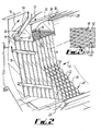
- a heat transfer assembly 10 which comprises an outer or main housing 12 which is of a cylindrical configuration, and a concentric inner or subsidiary housing 14.
- the heat transfer assembly 10 defines a first pathway 16 for the flow of a gas to be cooled and/or scrubbed, and a second pathway 18 for the flow of cooling and scrubbing water.
- the assembly 10 also includes a matrix arrangement 20, which is shown more clearly in Fig 2 , and comprises a plurality of sheets 22 of a mesh material which are arranged to define a plurality of channels 24 each having a diamond shaped profile.
- the channels 24 extend generally vertically to accommodate the flow of water 18 through the matrix arrangement 20. As can be seen, there are a plurality of rows of the channels 24 extending across the matrix arrangement 20.
- the inner casing 14 comprises first and second concentric skins 26, 28.
- the skins 26, 28 have an upper region defining a guide member in the form of a conduit 30, providing part of the second fluid path 18.
- Feeding means in the form of a water dispersion region 32 is provided above the matrix arrangement 20 and is defined to the front and rear by a first wall 36 depending from the first skin 26, and a second wall 38 depending from the second skin 28.
- the dispersion chamber 32 is also defined by the skin 26 extending around the matrix arrangement 20.
- the heat transfer assembly also includes a fluid outlet conduit 40 extending from a lower region of the outer casing 12.
- the fluid outlet 40 allows cooling water which has been heated by the gas flowing across the matrix arrangement 20 to exit from the heat transfer arrangement 10.
- the heat transfer arrangement 10 also includes a fluid exhaust arrangement 42 which comprises an interior conduit 44 which includes vane members 46 arranged centrally within the conduit 44 adjacent the exit of the conduit 44.
- the fluid exhaust arrangement 42 also includes a separation chamber 48 to allow any water droplets in the gas being exhausted to be separated therefrom.
- the vane members 46 are provided to catch the water droplets in the gas flowing through the exhaust arrangement 42 and allow the water droplets therein to separate therefrom.
- One of the vane members 46 is shown in Fig 1A . It comprises a main portion 46A and a hook portion 46B extending along an edge 47 of the main portion 46A.
- the hook portion 46B is provided to catch the water droplets to separate them from the gas flowing through the exhaust arrangement 42.
- the fluid exhaust arrangement 42 also includes an exhaust conduit 50 provided at the top of the separation chamber 48 through which the gas can be exhausted. As can be seen from Fig 1 , the exit of the interior conduit 44 is flared outwardly.
- the heat transfer assembly 10 also includes spray means 52 having a feed conduit 54 attached to a supply of water and a spray nozzle 56 to spray water over the gas exiting from the matrix arrangement 20.
- the spray means 52 provides enhanced cooling of the gas flowing along the pathway 16.
- a service access door 60 is provided at one end of the main housing 12 to allow access for servicing of the heat transfer assembly 10. '
- the mesh material forming the sheet 22 comprises a plurality of elongate members in the form of flattened wires 62, each being arranged in a sinusoidal wave-like configuration where the crests 64 of one wave are attached to trough 66 of each adjacent wave, and vice-a-versa.
- This provides apertures 68 in the mesh which are of a generally diamond-shaped configuration.
- the wires 62 are generally of a flattened configuration having a height which is less than their width.
- the sheets 22 could be formed of a metal, which could be corrosion resistant, and could be a stainless steel.
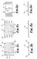
- Figs 3A, 3B, 4A, 4B, 5A and 5B are diagrammatic representations of a method of manufacturing the sheets 22.
- Figs 3A and 3B show respectively a plan view and a side view of one of the sheets 22 prior to its formation into a mesh.
- the sheet 22 in Figs 3A and 3B is provided with a plurality of rows 70 of slits 71 extending across the width 73 of the sheet 22.
- Figs 4A and 4B forces represented by the arrows X and Y are applied to opposite ends 72X and 72Y of the sheet 22.
- the forces cause the sheet 22 to stretch lengthwise, but narrow across its width 73 and to open the slits 71 into a plurality of diamond shaped apertures 68 extending across the sheet 22.
- Fig 5B shows a side view of the sheet 22 in Fig 5A and it can be seen that material of the sheet 22 extends out of the main plane thereof. As the sheet 22 is stretched, the flattened wires 62 twist slightly out of the plane of the sheet 22, giving the sheet 22 a front face 86 and a rear face 88.
- Figs. 6 and 7 show the sheet 22 in use.
- the flattened wires 62 each include a fluid contact surface 80, each of the fluid contact surfaces 80 forming a substantially continuous surface with the adjoining fluid contact surfaces 80 of adjacent flattened wires 62. With the plane of the sheet 22 substantially vertical, the fluid contact surfaces 80 are directed generally upwardly
- each fluid contact surface 80 is orientated at a first angle 82 to the sheet 22, the first angle being between 5° and 85°. In one example the first angle could be between 30° and 50°.
- Each sheet 22 is orientated at a second angle 84 to the vertical, the second angle 84 being between 0° and 45° and more preferably between 5° and 16°. In one example the second angle 84 could be substantially 11°.
- a gas flows along the gas flow pathway 16 through the apertures 68.
- a fluid such as water, which in one example could be seawater, flows along the liquid flow pathway 18 over the continuous fluid contact surfaces 80 and is brought into intimate contact with the gas thereby.
- the liquid spreads out thinly over the fluid contact surfaces 80 to wet the surfaces 80 by virtue of surface tension and gravity. It has been found that the orientation of the fluid contact surface 80 as defined by the first angle 82 and the second angle 84 and the continuous nature of the fluid contact surfaces 80 permits a relatively large cooling/cleaning effect to be obtained in a relatively small space.
- Fig. 2A is a view on the rear face 88. Any liquid flowing down this face 88 would be likely to flow through the sheet 22 to the front face 86 or be shed from the rear face 88.
- the applicant has realised that by careful orientation of the sheets 22, a matrix arrangement 20 having considerable advantages over conventional arrangements can be provided.
- the sheets 22 can be produced economically.
- the gas flow has a relatively low pressure drop.
- the efficiency of heat transfer and/or cleaning is relatively high.
- the arrangement can be used to cool and/or clean a variety of gases. The design is simple yet robust.
- the number of rows of the channels 22 can be varied.
- the mesh size, thickness and material can be varied to suit the use of the matrix arrangement.
- the apertures formed could be of any suitable size or shape.
- the matrix arrangement could include any suitable number of sheets, arranged in any suitable configuration.
Landscapes
- Engineering & Computer Science (AREA)
- Mechanical Engineering (AREA)
- General Engineering & Computer Science (AREA)
- Physics & Mathematics (AREA)
- Thermal Sciences (AREA)
- Heat-Exchange Devices With Radiators And Conduit Assemblies (AREA)
- Physical Or Chemical Processes And Apparatus (AREA)
- Gas Separation By Absorption (AREA)
- Solid-Sorbent Or Filter-Aiding Compositions (AREA)
Priority Applications (1)
| Application Number | Priority Date | Filing Date | Title |
|---|---|---|---|
| CY20131100679T CY1114204T1 (el) | 2006-03-21 | 2013-08-08 | Συγκροτημα για μεταφορα θερμοτητας ή καθαρισμο |
Applications Claiming Priority (2)
| Application Number | Priority Date | Filing Date | Title |
|---|---|---|---|
| GBGB0605599.0A GB0605599D0 (en) | 2006-03-21 | 2006-03-21 | Matrix arrangement |
| PCT/GB2007/001007 WO2007107754A1 (en) | 2006-03-21 | 2007-03-21 | Matrix arrangement |
Publications (2)
| Publication Number | Publication Date |
|---|---|
| EP2002192A1 EP2002192A1 (en) | 2008-12-17 |
| EP2002192B1 true EP2002192B1 (en) | 2013-05-15 |
Family
ID=36293133
Family Applications (1)
| Application Number | Title | Priority Date | Filing Date |
|---|---|---|---|
| EP07712939.3A Active EP2002192B1 (en) | 2006-03-21 | 2007-03-21 | Assembly for heat transfer or cleaning |
Country Status (12)
| Country | Link |
|---|---|
| US (1) | US8827248B2 (enExample) |
| EP (1) | EP2002192B1 (enExample) |
| JP (1) | JP5410956B2 (enExample) |
| KR (1) | KR101424241B1 (enExample) |
| CN (1) | CN101449126B (enExample) |
| AU (1) | AU2007228535B2 (enExample) |
| CY (1) | CY1114204T1 (enExample) |
| ES (1) | ES2423950T3 (enExample) |
| GB (1) | GB0605599D0 (enExample) |
| HR (1) | HRP20130729T1 (enExample) |
| NO (1) | NO339737B1 (enExample) |
| WO (1) | WO2007107754A1 (enExample) |
Families Citing this family (7)
| Publication number | Priority date | Publication date | Assignee | Title |
|---|---|---|---|---|
| JP3023755B2 (ja) | 1994-12-02 | 2000-03-21 | 小野田化学工業株式会社 | 珪酸カルシウム水和物成形体とその製造方法 |
| US8056338B2 (en) * | 2006-01-27 | 2011-11-15 | Borgwarner Inc. | Re-introduction unit for low-pressure exhaust gas recirculation condensate at or before compressor |
| JP5704238B2 (ja) * | 2011-07-28 | 2015-04-22 | 株式会社Ihi | ガス分離装置及び充填材 |
| CA2879264C (en) * | 2012-07-27 | 2017-05-30 | Ihi Corporation | Gas separation device and packing |
| CN106871499B (zh) * | 2017-02-23 | 2019-10-25 | 江苏利尔机车科技有限公司 | 一种结构灵活且易于拆装清洗的翅片式冷凝器 |
| EP3953655A4 (en) | 2019-07-02 | 2023-01-11 | Brentwood Industries, Inc. | Cooling tower splash bar hanger and related assembly |
| CA3143671C (en) | 2019-07-02 | 2023-02-21 | Brentwood Industries, Inc. | Cooling tower splash bar and related assembly |
Citations (2)
| Publication number | Priority date | Publication date | Assignee | Title |
|---|---|---|---|---|
| US4562015A (en) * | 1984-05-22 | 1985-12-31 | The Munters Corporation | Open mesh fill assembly |
| DE19733480A1 (de) * | 1997-08-01 | 1999-02-04 | Gea Energietechnik Gmbh | Einbaupackung zum Stoff- und/oder Wärmeaustausch zwischen Gasen und Flüssigkeiten |
Family Cites Families (23)
| Publication number | Priority date | Publication date | Assignee | Title |
|---|---|---|---|---|
| FR869527A (fr) | 1939-10-30 | 1942-02-04 | Krupp Ag | Appareil de réfrigération par évaporation à éléments de ruissellement montés verticalement, sous forme de plaques |
| GB607284A (en) | 1944-05-19 | 1948-08-27 | Francis Leopold Melvill | Improvements in gas or vapour and liquid contacting apparatus |
| US2470652A (en) * | 1946-11-30 | 1949-05-17 | Pan American Refining Corp | Industrial contacting material |
| DE1100597B (de) * | 1952-11-29 | 1961-03-02 | Atomic Energy Authority Uk | Packung fuer Dampf-Fluessigkeits- und Gas-Fluessigkeits-Gegenstrom-kontaktsaeulen |
| FR1164420A (fr) | 1956-01-16 | 1958-10-09 | Dispositif d'égalisation du niveau du liquide pour les plateaux d'échangeur avec introduction des gaz ou vapeurs dans un sens qui indique ou fixe le sens de circulation du liquide sur les plateaux | |
| SE307964B (enExample) * | 1964-03-24 | 1969-01-27 | C Munters | |
| US3346246A (en) * | 1965-01-25 | 1967-10-10 | Marley Co | Cooling tower fill assembly of foraminous sheet material |
| US3398060A (en) * | 1967-02-10 | 1968-08-20 | Desal Ltd | Process for continuous regenerative distillation of impure water |
| DE1601144A1 (de) | 1967-07-31 | 1970-11-05 | Seyerle Dr Ing Friedrich Wilhe | Waermeaustauscher fuer kondensierbare Daempfe und Gase,z.B. als Kondensator-Kuehler,zur Unterkuehlung oder Erwaermung nicht kondensierbarer,z.B.als Kopf von Kolonnen oder als Anbauteil zum Niederschlagen von Wrasen,Daempfen in Industriewaschmaschinen u.dgl. |
| US3947532A (en) * | 1974-06-17 | 1976-03-30 | Buffalo Forge Company | Liquid distribution strip |
| GB1470196A (en) * | 1974-11-13 | 1977-04-14 | Cooling Dev Ltd | Contact packing |
| US4304738A (en) * | 1979-10-15 | 1981-12-08 | Nutter Dale E | Packing Material and apparatus |
| DE3266166D1 (en) * | 1981-07-08 | 1985-10-17 | Kuehni Ag | Packing for material exchange columns, and process for producing the packing |
| CH667704A5 (de) | 1986-02-07 | 1988-10-31 | Sulzer Ag | Verfahren und vorrichtung zur gleichmaessigen verteilung einer fluessigkeit auf eine querschnittsflaeche. |
| US4934663A (en) * | 1989-09-20 | 1990-06-19 | Phelps Peter M | Cooling tower with sloping high density film fill sandwiched between low density film fill |
| JPH03284319A (ja) * | 1990-03-30 | 1991-12-16 | Baanaa Internatl:Kk | 空気処理エレメント及びこのエレメントを有する水膜型空気処理装置 |
| US5185106A (en) * | 1990-11-27 | 1993-02-09 | Glitsch, Inc. | Tower packing with small louvers and mixing method |
| NL1006152C1 (nl) * | 1996-11-27 | 1998-05-28 | Albert Van Duijn | Werkwijze en inrichting voor het mengen van een gas met een vloeistof. |
| JP2000317248A (ja) * | 1999-05-14 | 2000-11-21 | Yamaha Corp | ガス不純物の除去システム |
| DE50101102D1 (de) * | 2000-04-04 | 2004-01-22 | Sulzer Chemtech Ag Winterthur | Geordnete Kolonnenpackung mit einer Feinstrukturierung |
| JP4033677B2 (ja) * | 2002-01-09 | 2008-01-16 | 忠弘 大見 | 空気冷却方法 |
| JP2005156037A (ja) * | 2003-11-26 | 2005-06-16 | Nihon Spindle Techno Co Ltd | 直交流型冷却塔 |
| JP3112756U (ja) | 2005-05-23 | 2005-08-25 | 株式会社根岸製作所 | 揮発性有機化合物の処理装置 |
-
2006
- 2006-03-21 GB GBGB0605599.0A patent/GB0605599D0/en not_active Ceased
-
2007
- 2007-03-21 ES ES07712939T patent/ES2423950T3/es active Active
- 2007-03-21 AU AU2007228535A patent/AU2007228535B2/en not_active Ceased
- 2007-03-21 CN CN2007800185754A patent/CN101449126B/zh not_active Expired - Fee Related
- 2007-03-21 US US12/293,769 patent/US8827248B2/en not_active Expired - Fee Related
- 2007-03-21 WO PCT/GB2007/001007 patent/WO2007107754A1/en not_active Ceased
- 2007-03-21 KR KR1020087025760A patent/KR101424241B1/ko not_active Expired - Fee Related
- 2007-03-21 EP EP07712939.3A patent/EP2002192B1/en active Active
- 2007-03-21 HR HRP20130729TT patent/HRP20130729T1/hr unknown
- 2007-03-21 JP JP2009500922A patent/JP5410956B2/ja not_active Expired - Fee Related
-
2008
- 2008-10-21 NO NO20084413A patent/NO339737B1/no not_active IP Right Cessation
-
2013
- 2013-08-08 CY CY20131100679T patent/CY1114204T1/el unknown
Patent Citations (3)
| Publication number | Priority date | Publication date | Assignee | Title |
|---|---|---|---|---|
| US4562015A (en) * | 1984-05-22 | 1985-12-31 | The Munters Corporation | Open mesh fill assembly |
| DE19733480A1 (de) * | 1997-08-01 | 1999-02-04 | Gea Energietechnik Gmbh | Einbaupackung zum Stoff- und/oder Wärmeaustausch zwischen Gasen und Flüssigkeiten |
| US6096407A (en) * | 1997-08-01 | 2000-08-01 | Gea Energietechnik Gmbh | Built-in packing for material exchange and/or heat exchange between gases and liquids |
Also Published As
| Publication number | Publication date |
|---|---|
| US20090151915A1 (en) | 2009-06-18 |
| EP2002192A1 (en) | 2008-12-17 |
| CN101449126A (zh) | 2009-06-03 |
| NO339737B1 (no) | 2017-01-30 |
| JP2009530097A (ja) | 2009-08-27 |
| HRP20130729T1 (hr) | 2013-10-11 |
| JP5410956B2 (ja) | 2014-02-05 |
| KR20090021148A (ko) | 2009-02-27 |
| CY1114204T1 (el) | 2016-08-31 |
| GB0605599D0 (en) | 2006-04-26 |
| CN101449126B (zh) | 2011-11-23 |
| AU2007228535A1 (en) | 2007-09-27 |
| US8827248B2 (en) | 2014-09-09 |
| ES2423950T3 (es) | 2013-09-25 |
| AU2007228535B2 (en) | 2011-07-14 |
| WO2007107754A1 (en) | 2007-09-27 |
| KR101424241B1 (ko) | 2014-07-28 |
| NO20084413L (no) | 2008-10-31 |
Similar Documents
| Publication | Publication Date | Title |
|---|---|---|
| EP2002192B1 (en) | Assembly for heat transfer or cleaning | |
| US4562015A (en) | Open mesh fill assembly | |
| CA2805373C (en) | Evaporative heat exchange apparatus with finned elliptical tube coil assembly | |
| US10048020B2 (en) | Heat transfer surfaces with flanged apertures | |
| CA1291417C (en) | Tower packing element with embossed surfaces | |
| US11175097B2 (en) | Packing for heat and/or mass transfer | |
| US7059397B2 (en) | Heat exchanger with brazed plates | |
| KR20240007761A (ko) | 구조화된 패킹 및 이를 이용하는 교차 유동 접촉기 | |
| US4385012A (en) | Phase-contacting apparatus | |
| JPS6038161B2 (ja) | 改良された気液接触グリツド装置及びその作製方法 | |
| WO2011127574A1 (en) | Turbulator and conduit apparatus for a heat exchanger | |
| RU28766U1 (ru) | Ороситель градирни | |
| EP2064509B1 (en) | Heat transfer surfaces with flanged apertures | |
| US4202408A (en) | Jet type heat exchanger | |
| RU2384362C1 (ru) | Регулярная насадка | |
| KR100950198B1 (ko) | 열전달용 박판구조 및 그 열전달장치 | |
| SU1669535A1 (ru) | Пакет насадки | |
| RU136552U1 (ru) | Контактное устройство с закрученным движением потоков для тепло- и массообменных процессов | |
| RU2640263C1 (ru) | Теплообменник | |
| RU2232960C1 (ru) | Способ изготовления оросителя градирни | |
| RU14014U1 (ru) | Блок структурированной насадки | |
| RU2335725C1 (ru) | Ороситель градирни | |
| CN118056109A (zh) | 直接热交换填料 | |
| UA78527C2 (en) | Preformed packing for heat-mass transfer apparatus |
Legal Events
| Date | Code | Title | Description |
|---|---|---|---|
| PUAI | Public reference made under article 153(3) epc to a published international application that has entered the european phase |
Free format text: ORIGINAL CODE: 0009012 |
|
| 17P | Request for examination filed |
Effective date: 20081020 |
|
| AK | Designated contracting states |
Kind code of ref document: A1 Designated state(s): AT BE BG CH CY CZ DE DK EE ES FI FR GB GR HU IE IS IT LI LT LU LV MC MT NL PL PT RO SE SI SK TR |
|
| AX | Request for extension of the european patent |
Extension state: HR |
|
| 17Q | First examination report despatched |
Effective date: 20100429 |
|
| RAP1 | Party data changed (applicant data changed or rights of an application transferred) |
Owner name: COLDHARBOUR MARINE LIMITED |
|
| RAX | Requested extension states of the european patent have changed |
Extension state: HR Payment date: 20081020 |
|
| GRAP | Despatch of communication of intention to grant a patent |
Free format text: ORIGINAL CODE: EPIDOSNIGR1 |
|
| GRAS | Grant fee paid |
Free format text: ORIGINAL CODE: EPIDOSNIGR3 |
|
| GRAA | (expected) grant |
Free format text: ORIGINAL CODE: 0009210 |
|
| AK | Designated contracting states |
Kind code of ref document: B1 Designated state(s): AT BE BG CH CY CZ DE DK EE ES FI FR GB GR HU IE IS IT LI LT LU LV MC MT NL PL PT RO SE SI SK TR |
|
| AX | Request for extension of the european patent |
Extension state: HR |
|
| REG | Reference to a national code |
Ref country code: GB Ref legal event code: FG4D Ref country code: CH Ref legal event code: EP |
|
| REG | Reference to a national code |
Ref country code: AT Ref legal event code: REF Ref document number: 612366 Country of ref document: AT Kind code of ref document: T Effective date: 20130615 |
|
| REG | Reference to a national code |
Ref country code: IE Ref legal event code: FG4D |
|
| REG | Reference to a national code |
Ref country code: DE Ref legal event code: R096 Ref document number: 602007030436 Country of ref document: DE Effective date: 20130711 |
|
| REG | Reference to a national code |
Ref country code: HR Ref legal event code: TUEP Ref document number: P20130729 Country of ref document: HR |
|
| REG | Reference to a national code |
Ref country code: ES Ref legal event code: FG2A Ref document number: 2423950 Country of ref document: ES Kind code of ref document: T3 Effective date: 20130925 |
|
| REG | Reference to a national code |
Ref country code: HR Ref legal event code: T1PR Ref document number: P20130729 Country of ref document: HR |
|
| REG | Reference to a national code |
Ref country code: AT Ref legal event code: MK05 Ref document number: 612366 Country of ref document: AT Kind code of ref document: T Effective date: 20130515 |
|
| REG | Reference to a national code |
Ref country code: GR Ref legal event code: EP Ref document number: 20130401644 Country of ref document: GR Effective date: 20130920 |
|
| REG | Reference to a national code |
Ref country code: LT Ref legal event code: MG4D |
|
| REG | Reference to a national code |
Ref country code: NL Ref legal event code: VDEP Effective date: 20130515 |
|
| PG25 | Lapsed in a contracting state [announced via postgrant information from national office to epo] |
Ref country code: LT Free format text: LAPSE BECAUSE OF FAILURE TO SUBMIT A TRANSLATION OF THE DESCRIPTION OR TO PAY THE FEE WITHIN THE PRESCRIBED TIME-LIMIT Effective date: 20130515 Ref country code: IS Free format text: LAPSE BECAUSE OF FAILURE TO SUBMIT A TRANSLATION OF THE DESCRIPTION OR TO PAY THE FEE WITHIN THE PRESCRIBED TIME-LIMIT Effective date: 20130915 Ref country code: PT Free format text: LAPSE BECAUSE OF FAILURE TO SUBMIT A TRANSLATION OF THE DESCRIPTION OR TO PAY THE FEE WITHIN THE PRESCRIBED TIME-LIMIT Effective date: 20130916 Ref country code: SE Free format text: LAPSE BECAUSE OF FAILURE TO SUBMIT A TRANSLATION OF THE DESCRIPTION OR TO PAY THE FEE WITHIN THE PRESCRIBED TIME-LIMIT Effective date: 20130515 Ref country code: AT Free format text: LAPSE BECAUSE OF FAILURE TO SUBMIT A TRANSLATION OF THE DESCRIPTION OR TO PAY THE FEE WITHIN THE PRESCRIBED TIME-LIMIT Effective date: 20130515 Ref country code: SI Free format text: LAPSE BECAUSE OF FAILURE TO SUBMIT A TRANSLATION OF THE DESCRIPTION OR TO PAY THE FEE WITHIN THE PRESCRIBED TIME-LIMIT Effective date: 20130515 Ref country code: FI Free format text: LAPSE BECAUSE OF FAILURE TO SUBMIT A TRANSLATION OF THE DESCRIPTION OR TO PAY THE FEE WITHIN THE PRESCRIBED TIME-LIMIT Effective date: 20130515 |
|
| PG25 | Lapsed in a contracting state [announced via postgrant information from national office to epo] |
Ref country code: PL Free format text: LAPSE BECAUSE OF FAILURE TO SUBMIT A TRANSLATION OF THE DESCRIPTION OR TO PAY THE FEE WITHIN THE PRESCRIBED TIME-LIMIT Effective date: 20130515 Ref country code: BG Free format text: LAPSE BECAUSE OF FAILURE TO SUBMIT A TRANSLATION OF THE DESCRIPTION OR TO PAY THE FEE WITHIN THE PRESCRIBED TIME-LIMIT Effective date: 20130815 |
|
| PG25 | Lapsed in a contracting state [announced via postgrant information from national office to epo] |
Ref country code: LV Free format text: LAPSE BECAUSE OF FAILURE TO SUBMIT A TRANSLATION OF THE DESCRIPTION OR TO PAY THE FEE WITHIN THE PRESCRIBED TIME-LIMIT Effective date: 20130515 |
|
| PG25 | Lapsed in a contracting state [announced via postgrant information from national office to epo] |
Ref country code: EE Free format text: LAPSE BECAUSE OF FAILURE TO SUBMIT A TRANSLATION OF THE DESCRIPTION OR TO PAY THE FEE WITHIN THE PRESCRIBED TIME-LIMIT Effective date: 20130515 Ref country code: BE Free format text: LAPSE BECAUSE OF FAILURE TO SUBMIT A TRANSLATION OF THE DESCRIPTION OR TO PAY THE FEE WITHIN THE PRESCRIBED TIME-LIMIT Effective date: 20130515 Ref country code: CZ Free format text: LAPSE BECAUSE OF FAILURE TO SUBMIT A TRANSLATION OF THE DESCRIPTION OR TO PAY THE FEE WITHIN THE PRESCRIBED TIME-LIMIT Effective date: 20130515 Ref country code: DK Free format text: LAPSE BECAUSE OF FAILURE TO SUBMIT A TRANSLATION OF THE DESCRIPTION OR TO PAY THE FEE WITHIN THE PRESCRIBED TIME-LIMIT Effective date: 20130515 Ref country code: SK Free format text: LAPSE BECAUSE OF FAILURE TO SUBMIT A TRANSLATION OF THE DESCRIPTION OR TO PAY THE FEE WITHIN THE PRESCRIBED TIME-LIMIT Effective date: 20130515 |
|
| PG25 | Lapsed in a contracting state [announced via postgrant information from national office to epo] |
Ref country code: RO Free format text: LAPSE BECAUSE OF FAILURE TO SUBMIT A TRANSLATION OF THE DESCRIPTION OR TO PAY THE FEE WITHIN THE PRESCRIBED TIME-LIMIT Effective date: 20130515 Ref country code: NL Free format text: LAPSE BECAUSE OF FAILURE TO SUBMIT A TRANSLATION OF THE DESCRIPTION OR TO PAY THE FEE WITHIN THE PRESCRIBED TIME-LIMIT Effective date: 20130515 |
|
| PLBE | No opposition filed within time limit |
Free format text: ORIGINAL CODE: 0009261 |
|
| STAA | Information on the status of an ep patent application or granted ep patent |
Free format text: STATUS: NO OPPOSITION FILED WITHIN TIME LIMIT |
|
| 26N | No opposition filed |
Effective date: 20140218 |
|
| REG | Reference to a national code |
Ref country code: DE Ref legal event code: R097 Ref document number: 602007030436 Country of ref document: DE Effective date: 20140218 |
|
| PG25 | Lapsed in a contracting state [announced via postgrant information from national office to epo] |
Ref country code: LU Free format text: LAPSE BECAUSE OF FAILURE TO SUBMIT A TRANSLATION OF THE DESCRIPTION OR TO PAY THE FEE WITHIN THE PRESCRIBED TIME-LIMIT Effective date: 20140321 |
|
| REG | Reference to a national code |
Ref country code: CH Ref legal event code: PL |
|
| REG | Reference to a national code |
Ref country code: IE Ref legal event code: MM4A |
|
| PG25 | Lapsed in a contracting state [announced via postgrant information from national office to epo] |
Ref country code: CH Free format text: LAPSE BECAUSE OF NON-PAYMENT OF DUE FEES Effective date: 20140331 Ref country code: LI Free format text: LAPSE BECAUSE OF NON-PAYMENT OF DUE FEES Effective date: 20140331 Ref country code: IE Free format text: LAPSE BECAUSE OF NON-PAYMENT OF DUE FEES Effective date: 20140321 |
|
| PG25 | Lapsed in a contracting state [announced via postgrant information from national office to epo] |
Ref country code: MT Free format text: LAPSE BECAUSE OF FAILURE TO SUBMIT A TRANSLATION OF THE DESCRIPTION OR TO PAY THE FEE WITHIN THE PRESCRIBED TIME-LIMIT Effective date: 20130515 |
|
| REG | Reference to a national code |
Ref country code: FR Ref legal event code: PLFP Year of fee payment: 10 |
|
| PG25 | Lapsed in a contracting state [announced via postgrant information from national office to epo] |
Ref country code: MC Free format text: LAPSE BECAUSE OF FAILURE TO SUBMIT A TRANSLATION OF THE DESCRIPTION OR TO PAY THE FEE WITHIN THE PRESCRIBED TIME-LIMIT Effective date: 20130515 |
|
| PG25 | Lapsed in a contracting state [announced via postgrant information from national office to epo] |
Ref country code: TR Free format text: LAPSE BECAUSE OF FAILURE TO SUBMIT A TRANSLATION OF THE DESCRIPTION OR TO PAY THE FEE WITHIN THE PRESCRIBED TIME-LIMIT Effective date: 20130515 Ref country code: HU Free format text: LAPSE BECAUSE OF FAILURE TO SUBMIT A TRANSLATION OF THE DESCRIPTION OR TO PAY THE FEE WITHIN THE PRESCRIBED TIME-LIMIT; INVALID AB INITIO Effective date: 20070321 |
|
| REG | Reference to a national code |
Ref country code: FR Ref legal event code: PLFP Year of fee payment: 11 |
|
| REG | Reference to a national code |
Ref country code: FR Ref legal event code: PLFP Year of fee payment: 12 |
|
| REG | Reference to a national code |
Ref country code: HR Ref legal event code: ODRP Ref document number: P20130729 Country of ref document: HR Payment date: 20190315 Year of fee payment: 13 |
|
| REG | Reference to a national code |
Ref country code: HR Ref legal event code: ODRP Ref document number: P20130729 Country of ref document: HR Payment date: 20200820 Year of fee payment: 14 |
|
| PGFP | Annual fee paid to national office [announced via postgrant information from national office to epo] |
Ref country code: ES Payment date: 20200824 Year of fee payment: 14 Ref country code: DE Payment date: 20200819 Year of fee payment: 14 Ref country code: FR Payment date: 20200821 Year of fee payment: 14 Ref country code: CY Payment date: 20200904 Year of fee payment: 14 |
|
| PGFP | Annual fee paid to national office [announced via postgrant information from national office to epo] |
Ref country code: IT Payment date: 20200821 Year of fee payment: 14 |
|
| PGFP | Annual fee paid to national office [announced via postgrant information from national office to epo] |
Ref country code: GR Payment date: 20210324 Year of fee payment: 15 |
|
| PGFP | Annual fee paid to national office [announced via postgrant information from national office to epo] |
Ref country code: GB Payment date: 20210324 Year of fee payment: 15 |
|
| REG | Reference to a national code |
Ref country code: DE Ref legal event code: R119 Ref document number: 602007030436 Country of ref document: DE |
|
| REG | Reference to a national code |
Ref country code: HR Ref legal event code: PBON Ref document number: P20130729 Country of ref document: HR Effective date: 20210321 |
|
| PG25 | Lapsed in a contracting state [announced via postgrant information from national office to epo] |
Ref country code: CY Free format text: LAPSE BECAUSE OF NON-PAYMENT OF DUE FEES Effective date: 20210321 |
|
| PG25 | Lapsed in a contracting state [announced via postgrant information from national office to epo] |
Ref country code: DE Free format text: LAPSE BECAUSE OF NON-PAYMENT OF DUE FEES Effective date: 20211001 Ref country code: FR Free format text: LAPSE BECAUSE OF NON-PAYMENT OF DUE FEES Effective date: 20210331 |
|
| PG25 | Lapsed in a contracting state [announced via postgrant information from national office to epo] |
Ref country code: IT Free format text: LAPSE BECAUSE OF NON-PAYMENT OF DUE FEES Effective date: 20210321 |
|
| REG | Reference to a national code |
Ref country code: ES Ref legal event code: FD2A Effective date: 20220523 |
|
| PG25 | Lapsed in a contracting state [announced via postgrant information from national office to epo] |
Ref country code: ES Free format text: LAPSE BECAUSE OF NON-PAYMENT OF DUE FEES Effective date: 20210322 |
|
| GBPC | Gb: european patent ceased through non-payment of renewal fee |
Effective date: 20220321 |
|
| PG25 | Lapsed in a contracting state [announced via postgrant information from national office to epo] |
Ref country code: GB Free format text: LAPSE BECAUSE OF NON-PAYMENT OF DUE FEES Effective date: 20220321 |
|
| PG25 | Lapsed in a contracting state [announced via postgrant information from national office to epo] |
Ref country code: GR Free format text: LAPSE BECAUSE OF NON-PAYMENT OF DUE FEES Effective date: 20221006 |