EP2002154B1 - Rollenschieber für moped - Google Patents
Rollenschieber für moped Download PDFInfo
- Publication number
- EP2002154B1 EP2002154B1 EP07758548.7A EP07758548A EP2002154B1 EP 2002154 B1 EP2002154 B1 EP 2002154B1 EP 07758548 A EP07758548 A EP 07758548A EP 2002154 B1 EP2002154 B1 EP 2002154B1
- Authority
- EP
- European Patent Office
- Prior art keywords
- vehicle
- cvt
- microprocessor
- motor
- servo motor
- Prior art date
- Legal status (The legal status is an assumption and is not a legal conclusion. Google has not performed a legal analysis and makes no representation as to the accuracy of the status listed.)
- Active
Links
Images

Classifications
-
- F—MECHANICAL ENGINEERING; LIGHTING; HEATING; WEAPONS; BLASTING
- F16—ENGINEERING ELEMENTS AND UNITS; GENERAL MEASURES FOR PRODUCING AND MAINTAINING EFFECTIVE FUNCTIONING OF MACHINES OR INSTALLATIONS; THERMAL INSULATION IN GENERAL
- F16H—GEARING
- F16H61/00—Control functions within control units of change-speed- or reversing-gearings for conveying rotary motion ; Control of exclusively fluid gearing, friction gearing, gearings with endless flexible members or other particular types of gearing
- F16H61/66—Control functions within control units of change-speed- or reversing-gearings for conveying rotary motion ; Control of exclusively fluid gearing, friction gearing, gearings with endless flexible members or other particular types of gearing specially adapted for continuously variable gearings
- F16H61/662—Control functions within control units of change-speed- or reversing-gearings for conveying rotary motion ; Control of exclusively fluid gearing, friction gearing, gearings with endless flexible members or other particular types of gearing specially adapted for continuously variable gearings with endless flexible members
- F16H61/66254—Control functions within control units of change-speed- or reversing-gearings for conveying rotary motion ; Control of exclusively fluid gearing, friction gearing, gearings with endless flexible members or other particular types of gearing specially adapted for continuously variable gearings with endless flexible members controlling of shifting being influenced by a signal derived from the engine and the main coupling
- F16H61/66259—Control functions within control units of change-speed- or reversing-gearings for conveying rotary motion ; Control of exclusively fluid gearing, friction gearing, gearings with endless flexible members or other particular types of gearing specially adapted for continuously variable gearings with endless flexible members controlling of shifting being influenced by a signal derived from the engine and the main coupling using electrical or electronical sensing or control means
-
- F—MECHANICAL ENGINEERING; LIGHTING; HEATING; WEAPONS; BLASTING
- F16—ENGINEERING ELEMENTS AND UNITS; GENERAL MEASURES FOR PRODUCING AND MAINTAINING EFFECTIVE FUNCTIONING OF MACHINES OR INSTALLATIONS; THERMAL INSULATION IN GENERAL
- F16H—GEARING
- F16H59/00—Control inputs to control units of change-speed- or reversing-gearings for conveying rotary motion
- F16H59/50—Inputs being a function of the status of the machine, e.g. position of doors or safety belts
-
- F—MECHANICAL ENGINEERING; LIGHTING; HEATING; WEAPONS; BLASTING
- F16—ENGINEERING ELEMENTS AND UNITS; GENERAL MEASURES FOR PRODUCING AND MAINTAINING EFFECTIVE FUNCTIONING OF MACHINES OR INSTALLATIONS; THERMAL INSULATION IN GENERAL
- F16H—GEARING
- F16H63/00—Control outputs from the control unit to change-speed- or reversing-gearings for conveying rotary motion or to other devices than the final output mechanism
- F16H63/02—Final output mechanisms therefor; Actuating means for the final output mechanisms
- F16H63/04—Final output mechanisms therefor; Actuating means for the final output mechanisms a single final output mechanism being moved by a single final actuating mechanism
- F16H63/06—Final output mechanisms therefor; Actuating means for the final output mechanisms a single final output mechanism being moved by a single final actuating mechanism the final output mechanism having an indefinite number of positions
- F16H63/062—Final output mechanisms therefor; Actuating means for the final output mechanisms a single final output mechanism being moved by a single final actuating mechanism the final output mechanism having an indefinite number of positions electric or electro-mechanical actuating means
-
- F—MECHANICAL ENGINEERING; LIGHTING; HEATING; WEAPONS; BLASTING
- F16—ENGINEERING ELEMENTS AND UNITS; GENERAL MEASURES FOR PRODUCING AND MAINTAINING EFFECTIVE FUNCTIONING OF MACHINES OR INSTALLATIONS; THERMAL INSULATION IN GENERAL
- F16H—GEARING
- F16H61/00—Control functions within control units of change-speed- or reversing-gearings for conveying rotary motion ; Control of exclusively fluid gearing, friction gearing, gearings with endless flexible members or other particular types of gearing
- F16H61/66—Control functions within control units of change-speed- or reversing-gearings for conveying rotary motion ; Control of exclusively fluid gearing, friction gearing, gearings with endless flexible members or other particular types of gearing specially adapted for continuously variable gearings
- F16H61/662—Control functions within control units of change-speed- or reversing-gearings for conveying rotary motion ; Control of exclusively fluid gearing, friction gearing, gearings with endless flexible members or other particular types of gearing specially adapted for continuously variable gearings with endless flexible members
- F16H61/66272—Control functions within control units of change-speed- or reversing-gearings for conveying rotary motion ; Control of exclusively fluid gearing, friction gearing, gearings with endless flexible members or other particular types of gearing specially adapted for continuously variable gearings with endless flexible members characterised by means for controlling the torque transmitting capability of the gearing
Definitions
- the present invention relates generally to a continuously variable transmission (CVT) and specifically to a system and method for providing an automated adjustment to a CVT.
- CVT continuously variable transmission
- a transmission is any mechanical linkage that converts an input torque to an output torque. It usually involves a series of gears that have differing diameters, allowing a first gear at a first rotation rate to link to a second gear rotating at a second rate.
- the most common application for transmissions is in a vehicle. For example, a car may have an automatic transmission or a manual transmission.
- a bicycle has a simple transmission that links the pedals to the hub of the rear wheel.
- Transmissions allow an input force to be converted into a more useful and appropriate output.
- a typical transmission may only have 4 or 5 ratios available.
- a four speed automatic transmission in a car has only 4 sets of output gears to couple to the engine's input.
- a ten speed bike has only ten ratios of input to output.
- a continuously variable transmission is a transmission that eliminates the need for a specified number of gears. Instead it allows an almost limitless number of input to output ratios. This is a benefit because it allows an output to be achieved (i.e. the speed of a vehicle) at an optimal input (i.e. the rpm of the engine). For example, an engine might be most efficient at 1800 rpm. In other words, the peak torque output for the engine might be achieved at this engine rpm, or perhaps the highest fuel economy. Consequently, it may be desirable to run at a specified RPM for an economy mode or a power mode. Yet, in third gear, the car might be going faster at 1800 rpm than the driver desires.
- a continuously variable transmission would allow an intermediate ratio to be achieved that allowed the optimal input to achieve the desired output.
- CVT transmissions have a variator for continuously variable adjustment of the ratio.
- a customary structure is a belt drive variator having two pairs of beveled pulleys and rotating a torque-transmitter element therein, such as a pushing linked band or a chain.
- the beveled pulleys are loaded with pressure from the transmission oil pump in order, on one hand, to actuate the ratio adjustment and, on the other, to ensure a contact pressure needed for transmission of the torque upon the belt drive element.
- Another usual structure is a swash plate variator in semi-toroidal or fully toroidal design.
- CVTs are exemplified by U.S. Pat. Nos. 6,419,608 and 7,011,600 assigned to Fallbrook Technologies of San Diego, California. In each of those applications the axial movement of a rod or an axial force (as indicated by numeral 11 in each reference) is used to vary the input-to-output ratio of such transmissions.
- US 2005/0037876 A discloses a belt CVT wherein the speed ratio is controlled by advancing or retracting a movable sheave by means of a step motor.
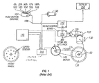
- FIG. 1 is a prior art schematic representation depicting the operation of manually controlled CVT or variator in a light electric vehicle, such as a scooter.
- a manual push button control box 101 has buttons corresponding to a signal output 108 of 0% 102 , 25% 103 , 50% 104 , 75% 105 , and 100% 106 sent to a microprocessor 112 .
- the microprocessor output can be shown on a display 150 .
- the microprocessor 112 interfaces with a motor control board 114 which receives power from a battery pack 118 .
- a servo motor 120 engages a 90-degree gearbox 122 which provides an axial force 130 to a variator (CVT) 132 in contact with the rear wheel 134 .
- the rear wheel 134 is powered by a chain 136 or other equivalent means connected to a drive motor 140 (e.g., Briggs & Stratton ETEK).
- the speed of the drive motor 140 is regulated by a current sent by a motor control device 144.
- the motor control device 144 is regulated by a throttle 146 and is powered by the battery 118 .
- the present invention provides a motorized vehicle and a method for automatically adjusting a continuously variable transmission (CVT) in a motorized vehicle, such as a battery powered scooter.
- CVT continuously variable transmission
- a motorized vehicle as defined in claim 1.
- a method as defined in claim 9 for automatically adjusting a continuously variable transmission (CVT) in a motorized vehicle for automatically adjusting a continuously variable transmission (CVT) in a motorized vehicle.
- CVT continuously variable transmission
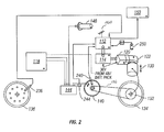
- FIG 2 is a schematic representation depicting the operation of an automatically controlled variator in a light electric vehicle in accordance with one embodiment of the present invention.
- the present invention uses one or more automatically-generated variables to automatically adjust the variator (CVT).
- the amount of current being drawn from the motor control device 144 comprises an automatically generated variable that can be used as an input signal to the microprocessor 112 .
- Motor controllers such as those available from Altrax of Grants Pass, OR can be used. Motor current draw is a function of throttle position and the state of the vehicle. For example:
- Another automatically generated variable supplied to the microprocessor 112 is the speed of the scooter, which is provided by a speed sensor 236 mounted on the front wheel 136 .
- a speed sensor 236 mounted on the front wheel 136 .
- multiple magnets e.g., 16
- the front wheel sensor 236 is mounted in a bracket from the wheel axel and wired into microprocessor 112 .
- the microprocessor 112 counts a pulse when a magnet passes the sensor 236 .
- the number of pulses in a given time period denotes the speed of the wheel, which is used to extrapolate the speed of the vehicle. This input is used in the calculation of optimized shifting to set a ratio in the variator 132 .
- Motor speed data provided by sensor 240 is another automatic variable that might be fed to the microprocessor 112 .
- the motor speed sensor 240 operates on the same principle as the front wheel sensor 236 .
- the signal provided by the sensor 240 gives a motor RPM value, which can be used to verify the transmission ratio using the following calculation:
- the variator gear reduction is derived from the front wheel speed sensor 236 and can be used to validate vehicle speed or transmission ratio to the "set ratio" of the control system.
- automatically generated variables include, but are not limited to:
- External data may also be provided to the microprocessor via a blue tooth antenna 260 .
- the twist throttle 146 gives the motor controller 144 an input signal from the rider. Based on the amount the throttle 146 is twisted, it increases a resistance value to the main motor controller 144 , which then translates this resistance value into voltage and current supplied to the drive motor 140 .
- the throttle is rated for 0 - 5k resistance.
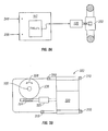
- Figure 3A is a schematic representation of the automatic operation of the shifter in accordance with one embodiment of the present invention.
- the microprocessor 112 comprises a basic stamp board available from Parallax, Inc. of Rocklin, CA.
- the microprocessor 112 can be programmed to generate lookup tables to provide optimum set points for variable inputs (described above) to obtain either the best performance or optimal efficiency of the scooter system.
- the microprocessor 112 receives data from the front wheel speed sensor 236 and current draw sensor 244 .
- the microprocessor 112 then outputs a signal to the servo 120 , which in turn provides an axial force to the variator 332 to shift in an optimal manner that minimizes current draw 244 or power drain so as to provide optimal efficiency.
- the data sampling speed and servo adjustment speed are adjusted to minimize power drain on the system that would otherwise cancel the efficiency gains.
- microprocessor output can be shown on a display 150 .
- This is an "on board" display of inputs and outputs that allows the user to verify settings and measurements during the testing phase. Examples of display readouts include:
- FIG. 3B is a schematic representation of the 90° gearbox in accordance with one embodiment of the present invention.
- the gearbox 322 comprises a servo 320 mounted with bolts 310 to the scooter frame (not shown).
- a coupler 323 is disposed between a threaded (worm) shaft 324 and the servo 320 .
- the wheel 326 rotates as depicted by numeral 328 , causing the shift shaft 330 to rotate.
- Such rotation of the shift shaft 330 is converted into an axial force.
- the 90° gearbox setup is used to provide a mechanical advantage (i.e. 36:1) and to reduce the size of the protrusion from the side of the scooter.
- the servo motor 320 When the system is turned on the servo motor 320 is driven towards home until the shift shaft 330 contacts the home sensor 250 (shown in Figure 2 ). The servo is stopped and the microprocessor 112 sets the internal electronic home position, registering voltage, turns, and rotation direction. In response to inputs from the sensors, based on the last known servo position a comparison is made between the current position and the "called" position. The microprocessor 112 then drives the servo 320 to the "called" position.
- Figure 4A is a simplified schematic representation of a linear actuator in accordance with an alternative embodiment of the present invention.
- This embodiment uses a rack and pinion setup and can be mounted up inside of the scooter.
- the end 416 of the threaded shaft 424 is adapted to couple between a first tooth-like member 412 and a second tooth-like member 414 .
- the first tooth-like member 412 is driven axially and thereby provides an axial force to a member 410 that is in communication with the tooth-like member 412 and a variator (not shown).
- FIG. 4B is a schematic representation of a servo motor mounted on the rear wheel in accordance with an alternate embodiment of the present invention.
- the servo motor 420 is connected to a shaft 430 having a threaded portion 424 adapted to couple with a threaded variator shaft (not shown).
- the internal threaded portion 424 allows space for the variator shaft to be pulled in and out.
- the servo motor 420 turns the shaft 430 thereby causing the threaded portion 424 to move the variator shaft in or out, thus adjusting the variator.
- FIG 4C is a schematic representation of an alternate servo motor design in accordance with another embodiment of the present invention.
- the servo motor 420 in this embodiment is also mounted at the rear wheel of the scooter.
- the servo motor 420 is connected to a shaft 430 having a splined portion 425 adapted to couple with a variator shaft (not shown).
- the servo motor 420 turns the splined shaft 430, thereby creating an axial force on the variator shaft, thus adjusting the variator.
- FIG. 4D is a schematic representation of the servo motor in communication with a hub that contains the variator in accordance with another alternate embodiment of the present invention.
- a hub 1102 containing the variator is mounted at the rear wheel of the scooter (not shown), and the servo motor is mounted up in the scooter.
- the rear hub 1102 includes a housing having an axial force that encloses and protects a pulley system coupled to cables 1012 and 1014 . These cables 1012 , 1014 in turn are connected to the servo motor 420 . which alternately pulls cable 1012 or cable 1014 in order to adjust the variator inside the hub 1102 .
Landscapes
- Engineering & Computer Science (AREA)
- General Engineering & Computer Science (AREA)
- Mechanical Engineering (AREA)
- Control Of Transmission Device (AREA)
- Transmissions By Endless Flexible Members (AREA)
- Electric Propulsion And Braking For Vehicles (AREA)
- Transmission Devices (AREA)
- Friction Gearing (AREA)
Claims (16)
- Motorfahrzeug mit einem System zur automatischen Justierung eines stufenlosen Getriebes (CVT-Getriebes) (132), wobei das Fahrzeug Folgendes umfasst:einen Mikroprozessor (112),mehrere Sensoren (236, 240), die für den Mikroprozessor (112) Daten zum Betriebszustand des Fahrzeugs bereitstellen, undeinen Servomotor (120) in mechanischer Verbindung mit dem CVT-Getriebe (132), wobei der Servo-motor (120) eine Axialkraft bereitstellt, um das CVT-Getriebe (132) zu justieren,wobei der Mikroprozessor (112) Nachschlagetabellen für optimale Sollwerte für Fahrzeugdaten erzeugt, um den Servomotor (120) anzuweisen, das Übersetzungsverhältnis des CVT-Getriebes (132) gemäß den durch die Sensoren (236, 240) bereitgestellten Fahrzeugdaten einzustellen, wobei die durch die Sensoren (236, 240) für den Mikroprozessor (112) bereitgestellten Fahrzeugdaten ein Signal aus der Gruppe umfassen, die aus Fahrzeuggeschwindigkeit, Motordrehzahl, Drosselklappenposition, Stromaufnahme von einer Batterie, Batteriefüllstand, CVT-Getriebe-Einstellung, Steuerungseinstellungen einer Motorsteuervorrichtung, Windrichtung, Windgeschwindigkeit und Reifendruck besteht, undeine Sichtanzeige (150), die dafür eingerichtet ist, Daten vom Mikroprozessor (112) anzuzeigen, wobei die Sichtanzeige (150) dafür gestaltet ist, einem Benutzer das Überprüfen von Einstellungen und Messwerten zu ermöglichen, wobei die Ablesewerte der Anzeige ein Signal der Gruppe umfassen, die aus Folgendem besteht:Anzahl der Räder,Stromstärke in A,Eingangsspannung,Stromsensor für den Motor,Motordrehzahl,Radumdrehungen/min undFahrzeuggeschwindigkeit.
- Fahrzeug nach Anspruch 1, wobei der Mikroprozessor (112) mit Nachschlagetabellen programmiert ist, um die optimalen Sollwerte für Fahrzeugdateneingaben bereitzustellen, um die beste Fahrzeugleistung zu erzielen.
- Fahrzeug nach Anspruch 1, wobei der Mikroprozessor (112) mit Nachschlagetabellen programmiert ist, um die optimalen Sollwerte für Fahrzeugdateneingaben bereitzustellen, um die beste Fahrzeugeffizienz zu erzielen.
- Fahrzeug nach Anspruch 1, ferner ein 90°-Winkelgetriebe (122) umfassend, das eine mechanische Verbindung zwischen dem Servomotor (120) und dem CVT-Getriebe (132) bereitstellt.
- Fahrzeug nach Anspruch 1, ferner einen Zahnstangen-Linearantrieb umfassend, der eine mechanische Verbindung zwischen dem Servomotor (120) und dem CVT-Getriebe (132) bereitstellt.
- Fahrzeug nach Anspruch 1, wobei der Servomotor (120) angrenzend an das CVT-Getriebe (132) an ein Fahrzeugrad montiert ist.
- Fahrzeug nach Anspruch 1, ferner ein Riemenscheibensystem und Riemen umfassend, die eine mechanische Verbindung zwischen dem Servomotor (120) und dem CVT-Getriebe (132) bereitstellen.
- Fahrzeug nach Anspruch 1, wobei das Kraftfahrzeug ein batteriebetriebener Motorroller ist.
- Verfahren zum automatischen Justieren eines stufenlosen Getriebes (CVT-Getriebes) (132) in einem motorisierten Fahrzeug, wobei das Verfahren folgende Schritte umfasst:Programmieren eines Mikroprozessors (112) im Fahrzeug, um Nachschlagetabellen für optimale Sollwerte für Fahrzeugdaten zu erzeugen,Bereitstellen von Daten zum Fahrzeugbetriebszustand von mehreren Sensoren (236, 240) für den Mikroprozessor (112),Senden von Befehlen vom Mikroprozessor (112) zu einem Servomotor (120), der mit dem CVT-Ge-triebe (132) in mechanischer Verbindung steht, um das Übersetzungsverhältnis des CVT-Getriebes (132) gemäß den durch die Sensoren (236, 240) bereitgestellten Daten zu justieren, wobei die durch die Sensoren (236, 240) für den Mikroprozessor (112) bereitgestellten Fahrzeugdaten ein Signal aus der Gruppe umfassen, die aus Fahrzeuggeschwindigkeit, Motordrehzahl, Drosselklappenposition, Stromaufnahme von einer Batterie, Batteriefüllstand, CVT-Getriebe-Einstellung, Steuerungseinstellungen einer Motorsteuervorrichtung, Windrichtung, Windgeschwindigkeit und Reifendruck besteht, undsichtbares Anzeigen (150) von Ein- und Ausgaben, die einem Benutzer das Überprüfen von Ein-stellungen und Messwerten ermöglichen, wobei die Ablesewerte der Anzeige ein Signal der Gruppe umfassen, die aus Folgendem besteht:Anzahl der Räder,Stromstärke in A,Eingangsspannung,Stromsensor für den Motor,Motordrehzahl,Radumdrehungen/min undFahrzeuggeschwindigkeit.
- Verfahren nach Anspruch 9, wobei der Mikroprozessor (112) mit Nachschlagetabellen programmiert wird, um die optimalen Sollwerte für Fahrzeugdateneingaben bereitzustellen, um die beste Fahrzeugleistung zu erzielen.
- Verfahren nach Anspruch 9, wobei der Mikroprozessor (112) mit Nachschlagetabellen programmiert wird, um die optimalen Sollwerte für Fahrzeugdateneingaben bereitzustellen, um die beste Fahrzeugeffizienz zu erzielen.
- Verfahren nach Anspruch 9, ferner das Bereitstellen einer mechanischen Verbindung zwischen dem Servomotor (120) und dem CVT-Getriebe (132) mit Hilfe eines 90°-Winkelgetriebes umfassend.
- Verfahren nach Anspruch 9, ferner das Bereitstellen einer mechanischen Verbindung zwischen dem Servomotor (120) und dem CVT-Getriebe (132) mit Hilfe eines Zahnstangen-Linearantriebes umfassend.
- Verfahren nach Anspruch 9, ferner das Montieren des Servomotors (120) an ein Fahrzeugrad, angrenzend an das CVT-Getriebe (132) umfassend.
- Verfahren nach Anspruch 9, ferner das Bereitstellen einer mechanischen Verbindung zwischen dem Servomotor (120) und dem CVT-Getriebe (132) mit Hilfe eines Riemenscheibensystems und von Riemen umfassend.
- Verfahren nach Anspruch 9, wobei das Kraftfahrzeug ein batteriebetriebener Motorroller ist.
Priority Applications (2)
| Application Number | Priority Date | Filing Date | Title |
|---|---|---|---|
| PL07758548T PL2002154T3 (pl) | 2006-03-14 | 2007-03-14 | Zmieniacz biegów skutera |
| EP13183460.8A EP2674644B1 (de) | 2006-03-14 | 2007-03-14 | Rollenschieber für Moped |
Applications Claiming Priority (2)
| Application Number | Priority Date | Filing Date | Title |
|---|---|---|---|
| US78310806P | 2006-03-14 | 2006-03-14 | |
| PCT/US2007/064003 WO2007106870A2 (en) | 2006-03-14 | 2007-03-14 | Scooter shifter |
Related Child Applications (1)
| Application Number | Title | Priority Date | Filing Date |
|---|---|---|---|
| EP13183460.8A Division EP2674644B1 (de) | 2006-03-14 | 2007-03-14 | Rollenschieber für Moped |
Publications (3)
| Publication Number | Publication Date |
|---|---|
| EP2002154A2 EP2002154A2 (de) | 2008-12-17 |
| EP2002154A4 EP2002154A4 (de) | 2011-11-30 |
| EP2002154B1 true EP2002154B1 (de) | 2013-10-02 |
Family
ID=38510278
Family Applications (2)
| Application Number | Title | Priority Date | Filing Date |
|---|---|---|---|
| EP07758548.7A Active EP2002154B1 (de) | 2006-03-14 | 2007-03-14 | Rollenschieber für moped |
| EP13183460.8A Active EP2674644B1 (de) | 2006-03-14 | 2007-03-14 | Rollenschieber für Moped |
Family Applications After (1)
| Application Number | Title | Priority Date | Filing Date |
|---|---|---|---|
| EP13183460.8A Active EP2674644B1 (de) | 2006-03-14 | 2007-03-14 | Rollenschieber für Moped |
Country Status (6)
| Country | Link |
|---|---|
| US (1) | US7885747B2 (de) |
| EP (2) | EP2002154B1 (de) |
| CN (2) | CN101438082B (de) |
| DK (1) | DK2002154T3 (de) |
| PL (1) | PL2002154T3 (de) |
| WO (1) | WO2007106870A2 (de) |
Families Citing this family (45)
| Publication number | Priority date | Publication date | Assignee | Title |
|---|---|---|---|---|
| EP2261537A3 (de) | 2001-04-26 | 2012-06-13 | Fallbrook Technologies Inc. | Stufenlos verstellbares Getriebe |
| US7011600B2 (en) | 2003-02-28 | 2006-03-14 | Fallbrook Technologies Inc. | Continuously variable transmission |
| MX364884B (es) | 2004-10-05 | 2019-05-10 | Fallbrook Intellectual Property Company Llc Star | Transmisión continuamente variable. |
| KR20130018976A (ko) | 2005-10-28 | 2013-02-25 | 폴브룩 테크놀로지즈 인크 | 전기 기계 동력 전달 방법 |
| US20070155567A1 (en) | 2005-11-22 | 2007-07-05 | Fallbrook Technologies Inc. | Continuously variable transmission |
| CN102226464B (zh) | 2005-12-09 | 2013-04-17 | 福博科技术公司 | 一种用于变速器的轴向力产生机构 |
| EP1811202A1 (de) * | 2005-12-30 | 2007-07-25 | Fallbrook Technologies, Inc. | Stufenloses Getriebe |
| US7882762B2 (en) * | 2006-01-30 | 2011-02-08 | Fallbrook Technologies Inc. | System for manipulating a continuously variable transmission |
| WO2007106874A2 (en) * | 2006-03-14 | 2007-09-20 | Autocraft Industries, Inc. | Improved wheelchair |
| CN102269056B (zh) | 2006-06-26 | 2013-10-23 | 福博科技术公司 | 无级变速器 |
| EP2089642B1 (de) | 2006-11-08 | 2013-04-10 | Fallbrook Intellectual Property Company LLC | Klemmkraftgenerator |
| EP2125469A2 (de) | 2007-02-01 | 2009-12-02 | Fallbrook Technologies Inc. | System und verfahren zur getriebe- und/oder antriebsmotorsteuerung |
| CN101657653B (zh) | 2007-02-12 | 2014-07-16 | 福博科知识产权有限责任公司 | 一种传动装置 |
| WO2008101070A2 (en) | 2007-02-16 | 2008-08-21 | Fallbrook Technologies Inc. | Infinitely variable transmissions, continuously variable transmissions, methods, assemblies, subassemblies, and components therefor |
| EP2142826B1 (de) | 2007-04-24 | 2015-10-28 | Fallbrook Intellectual Property Company LLC | Elektrische zugvorrichtungen |
| US8641577B2 (en) * | 2007-06-11 | 2014-02-04 | Fallbrook Intellectual Property Company Llc | Continuously variable transmission |
| KR20100046166A (ko) | 2007-07-05 | 2010-05-06 | 폴브룩 테크놀로지즈 인크 | 연속 가변 변속기 |
| CN103939602B (zh) | 2007-11-16 | 2016-12-07 | 福博科知识产权有限责任公司 | 用于变速传动装置的控制器 |
| EP2234869B1 (de) | 2007-12-21 | 2012-07-04 | Fallbrook Technologies Inc. | Automatikgetriebe und verfahren dafür |
| WO2009111328A1 (en) | 2008-02-29 | 2009-09-11 | Fallbrook Technologies Inc. | Continuously and/or infinitely variable transmissions and methods therefor |
| US8317651B2 (en) | 2008-05-07 | 2012-11-27 | Fallbrook Intellectual Property Company Llc | Assemblies and methods for clamping force generation |
| JP5457438B2 (ja) | 2008-06-06 | 2014-04-02 | フォールブルック インテレクチュアル プロパティー カンパニー エルエルシー | 無限可変変速機、及び無限可変変速機用の制御システム |
| CN107246463A (zh) | 2008-06-23 | 2017-10-13 | 福博科知识产权有限责任公司 | 无级变速器 |
| WO2010017242A1 (en) * | 2008-08-05 | 2010-02-11 | Fallbrook Technologies Inc. | Methods for control of transmission and prime mover |
| US8469856B2 (en) | 2008-08-26 | 2013-06-25 | Fallbrook Intellectual Property Company Llc | Continuously variable transmission |
| US8167759B2 (en) | 2008-10-14 | 2012-05-01 | Fallbrook Technologies Inc. | Continuously variable transmission |
| KR101718754B1 (ko) | 2009-04-16 | 2017-03-22 | 폴브룩 인텔렉츄얼 프로퍼티 컴퍼니 엘엘씨 | 무단 변속기를 위한 고정자 조립체 및 시프팅 장치 |
| US8512195B2 (en) * | 2010-03-03 | 2013-08-20 | Fallbrook Intellectual Property Company Llc | Infinitely variable transmissions, continuously variable transmissions, methods, assemblies, subassemblies, and components therefor |
| US8888643B2 (en) | 2010-11-10 | 2014-11-18 | Fallbrook Intellectual Property Company Llc | Continuously variable transmission |
| US9327792B2 (en) | 2011-01-28 | 2016-05-03 | Paha Designs, Llc | Gear transmission and derailleur system |
| US10207772B2 (en) | 2011-01-28 | 2019-02-19 | Paha Designs, Llc | Gear transmission and derailleur system |
| US9033833B2 (en) | 2011-01-28 | 2015-05-19 | Paha Designs, Llc | Gear transmission and derailleur system |
| WO2012138610A1 (en) | 2011-04-04 | 2012-10-11 | Fallbrook Intellectual Property Company Llc | Auxiliary power unit having a continuously variable transmission |
| JP6175450B2 (ja) | 2012-01-23 | 2017-08-02 | フォールブルック インテレクチュアル プロパティー カンパニー エルエルシー | 無限可変変速機、連続可変変速機、方法、組立体、部分組立体およびその構成要素 |
| CN109018173B (zh) | 2013-04-19 | 2021-05-28 | 福博科知识产权有限责任公司 | 无级变速器 |
| US9285031B1 (en) * | 2014-11-14 | 2016-03-15 | GM Global Technology Operations LLC | Method and apparatus to control a continuously variable transmission |
| US10047861B2 (en) | 2016-01-15 | 2018-08-14 | Fallbrook Intellectual Property Company Llc | Systems and methods for controlling rollback in continuously variable transmissions |
| US10458526B2 (en) | 2016-03-18 | 2019-10-29 | Fallbrook Intellectual Property Company Llc | Continuously variable transmissions, systems and methods |
| BE1023741B1 (nl) * | 2016-04-28 | 2017-07-07 | Punch Powertrain Nv | Een voertuig, een continu variabele transmissie systeem, een besturingswerkwijze en een computerprogrammaproduct |
| US10023266B2 (en) | 2016-05-11 | 2018-07-17 | Fallbrook Intellectual Property Company Llc | Systems and methods for automatic configuration and automatic calibration of continuously variable transmissions and bicycles having continuously variable transmissions |
| US10189543B2 (en) * | 2016-08-03 | 2019-01-29 | Kuo-Hsin Su | Electric motorcycle with improved motor performance |
| CN108578993B (zh) * | 2018-07-12 | 2024-07-23 | 郑州航空港区羽丰医疗科技有限公司 | 一种功率车 |
| US11215268B2 (en) | 2018-11-06 | 2022-01-04 | Fallbrook Intellectual Property Company Llc | Continuously variable transmissions, synchronous shifting, twin countershafts and methods for control of same |
| US11174922B2 (en) | 2019-02-26 | 2021-11-16 | Fallbrook Intellectual Property Company Llc | Reversible variable drives and systems and methods for control in forward and reverse directions |
| US11313447B1 (en) * | 2020-07-20 | 2022-04-26 | Jiangsu University | Power-split hydro-mechanical hybrid transmission system with automatic adjustment function |
Family Cites Families (29)
| Publication number | Priority date | Publication date | Assignee | Title |
|---|---|---|---|---|
| US4706518A (en) | 1984-04-30 | 1987-11-17 | Aisin Warner Kabushiki Kaisha | Automatic transmission having C.V.T. system for a vehicle |
| JPS6444394A (en) * | 1987-08-11 | 1989-02-16 | Honda Motor Co Ltd | Controller for non-stage transmission |
| US5269726A (en) * | 1991-06-26 | 1993-12-14 | Borg-Warner Automotive, Inc. | Control system and strategies for a double acting secondary sheave servo for a continuously variable transmission |
| DE4223967A1 (de) * | 1992-07-21 | 1994-01-27 | Bosch Gmbh Robert | Einrichtung zur Einstellung eines Getriebe-Abtriebsmoments oder einer Getriebe-Ausgangsleistung bei Fahrzeugen mit kontinuierlich verstellbarem Getriebe (CVT) |
| US5514047A (en) | 1993-03-08 | 1996-05-07 | Ford Motor Company | Continuously variable transmission |
| JP3058005B2 (ja) * | 1994-04-28 | 2000-07-04 | 日産自動車株式会社 | 無段変速機の制御装置 |
| JP3450078B2 (ja) * | 1995-01-30 | 2003-09-22 | セイコーエプソン株式会社 | 電気自動車のパワーアシスト装置 |
| EP0733831B1 (de) | 1995-03-24 | 2002-01-09 | Aisin Aw Co., Ltd. | Stufenloses Getriebe |
| EP0873482B1 (de) * | 1996-01-11 | 2000-08-30 | Siemens Aktiengesellschaft | Steuerung für eine einrichtung in einem kraftfahrzeug |
| JP3409669B2 (ja) * | 1997-03-07 | 2003-05-26 | 日産自動車株式会社 | 無段変速機の変速制御装置 |
| US6419608B1 (en) * | 1999-10-22 | 2002-07-16 | Motion Technologies, Llc | Continuously variable transmission |
| DE19833699A1 (de) | 1998-07-27 | 2000-02-03 | Zahnradfabrik Friedrichshafen | Verfahren zur Einstellung einer Übersetzung eines stufenlosen Automatgetriebes mit einem Variator |
| WO2000025042A1 (de) * | 1998-10-23 | 2000-05-04 | Siemens Aktiengesellschaft | Verfahren zum steuern und steuerung für ein stufenloses automatisches kraftfahrzeug-getriebe |
| DE19851160A1 (de) | 1998-11-06 | 2000-05-18 | Zf Batavia Llc | Einrichtung zur Steuerung eines Automatikgetriebes |
| DE19851738A1 (de) * | 1998-11-10 | 2000-05-18 | Getrag Getriebe Zahnrad | Triebstrang für ein Kraftfahrzeug |
| US6520878B1 (en) | 1999-04-23 | 2003-02-18 | Cvtech R & D Inc. | Driving pulley for scooters and other vehicles |
| US6266931B1 (en) * | 1999-06-10 | 2001-07-31 | Atwood Industries, Inc. | Screw drive room slideout assembly |
| JP3546302B2 (ja) * | 1999-08-05 | 2004-07-28 | トヨタ自動車株式会社 | 無段変速機を備えた車両の制御装置 |
| EP1099884A3 (de) * | 1999-11-10 | 2003-04-16 | Nissan Motor Co., Ltd. | Steuereinrichtung eines stufenlosen Toroidgetriebes |
| DE10059450A1 (de) | 2000-11-30 | 2002-06-13 | Zf Batavia Llc | Akustische Erkennung von Variatorschlupf bei CVT-Getrieben |
| GB2371839A (en) * | 2001-02-01 | 2002-08-07 | Eaton Corp | Control for selecting automated transmission system shift strategy |
| US7077023B2 (en) | 2001-02-13 | 2006-07-18 | Nissan Motor Co., Ltd. | Toroidal continuously variable transmission |
| TWI268320B (en) * | 2001-12-04 | 2006-12-11 | Yamaha Motor Co Ltd | Continuously variable transmission and method of controlling it allowing for control of the axial position of a movable sheave without a sensor for measuring the axial position of the movable sheave on a rotational shaft and for stable control with the movable sheave being held in position |
| EP1474623A2 (de) | 2002-02-07 | 2004-11-10 | LuK Lamellen und Kupplungsbau Beteiligungs KG | Verfahren zum regeln der bersetzung eines leistungsverzweig ten automatischen getriebes sowie leistungsverzweigtes automatisches getriebe |
| JP3817516B2 (ja) * | 2002-12-26 | 2006-09-06 | 本田技研工業株式会社 | ハイブリッド車両の駆動制御装置 |
| US7011600B2 (en) | 2003-02-28 | 2006-03-14 | Fallbrook Technologies Inc. | Continuously variable transmission |
| US7261672B2 (en) * | 2003-03-19 | 2007-08-28 | The Regents Of The University Of California | Method and system for controlling rate of change of ratio in a continuously variable transmission |
| JP4553298B2 (ja) * | 2004-08-05 | 2010-09-29 | 本田技研工業株式会社 | 電動車両のモータ冷却構造 |
| JP2006069397A (ja) * | 2004-09-02 | 2006-03-16 | Toyota Motor Corp | 車両用ドアモジュール構造 |
-
2007
- 2007-03-14 PL PL07758548T patent/PL2002154T3/pl unknown
- 2007-03-14 EP EP07758548.7A patent/EP2002154B1/de active Active
- 2007-03-14 DK DK07758548.7T patent/DK2002154T3/da active
- 2007-03-14 WO PCT/US2007/064003 patent/WO2007106870A2/en not_active Ceased
- 2007-03-14 CN CN200780016360.9A patent/CN101438082B/zh active Active
- 2007-03-14 CN CN201410305249.3A patent/CN104154203A/zh active Pending
- 2007-03-14 US US11/686,231 patent/US7885747B2/en active Active
- 2007-03-14 EP EP13183460.8A patent/EP2674644B1/de active Active
Also Published As
| Publication number | Publication date |
|---|---|
| US7885747B2 (en) | 2011-02-08 |
| WO2007106870A3 (en) | 2007-12-06 |
| EP2002154A4 (de) | 2011-11-30 |
| PL2002154T3 (pl) | 2014-02-28 |
| EP2002154A2 (de) | 2008-12-17 |
| CN101438082A (zh) | 2009-05-20 |
| CN101438082B (zh) | 2014-07-30 |
| DK2002154T3 (da) | 2014-01-13 |
| EP2674644B1 (de) | 2019-07-24 |
| US20070219696A1 (en) | 2007-09-20 |
| WO2007106870A2 (en) | 2007-09-20 |
| EP2674644A1 (de) | 2013-12-18 |
| CN104154203A (zh) | 2014-11-19 |
Similar Documents
| Publication | Publication Date | Title |
|---|---|---|
| EP2002154B1 (de) | Rollenschieber für moped | |
| US8087482B2 (en) | Wheelchair | |
| US10343746B2 (en) | Drive assembly for a manually driven vehicle with an electric auxiliary drive, method for regulating a drive assembly of this type, and use | |
| JP5630718B2 (ja) | 遊星ギアを用いた動力伝達装置 | |
| KR101132753B1 (ko) | 유성기어세트 및 이를 이용한 동력 전달 장치 | |
| CN212290182U (zh) | 中置电机驱动系统 | |
| WO2003002890A1 (en) | Multi-speed worm gear reduction assembly | |
| JP4191362B2 (ja) | 無段変速機の制御方法 | |
| CN217227830U (zh) | 中置电机的牙盘变速装置及其中置电机 | |
| CN101907153A (zh) | 汽车智能无级变速箱 | |
| CN221221396U (zh) | 电子换挡机构及全地形车 | |
| HK1192302A (en) | Scooter shifter | |
| CN115571258A (zh) | 中置电机的牙盘变速装置及其中置电机 | |
| CN201031948Y (zh) | 多段式动力自动调速器 | |
| KR100925687B1 (ko) | 사륜차량의 동력전달구조 | |
| CN223120526U (zh) | 三轮车用电子变挡的多挡变速器总成 | |
| CN2890499Y (zh) | 内置倒档发动机的减速、变档机构 | |
| WO2004081412A1 (en) | Forward-reverse control device | |
| EP4467436B1 (de) | Stufenloses getriebe für fahrrad | |
| CN216623075U (zh) | 一种遥控操作装置 | |
| CN217108077U (zh) | 一种电动车后桥变速器 | |
| CN219101971U (zh) | 一种无级变速器 | |
| CN101038018A (zh) | 内置倒档发动机的减速、变档机构 | |
| EP1528298A1 (de) | Schaltmechanismus für Synchrongetriebe | |
| WO2025032456A1 (en) | Improved transmission system for a pedal vehicle and related control method |
Legal Events
| Date | Code | Title | Description |
|---|---|---|---|
| PUAI | Public reference made under article 153(3) epc to a published international application that has entered the european phase |
Free format text: ORIGINAL CODE: 0009012 |
|
| 17P | Request for examination filed |
Effective date: 20081014 |
|
| AK | Designated contracting states |
Kind code of ref document: A2 Designated state(s): AT BE BG CH CY CZ DE DK EE ES FI FR GB GR HU IE IS IT LI LT LU LV MC MT NL PL PT RO SE SI SK TR |
|
| RAP1 | Party data changed (applicant data changed or rights of an application transferred) |
Owner name: FALLBROOK TECHNOLOGIES INC. |
|
| A4 | Supplementary search report drawn up and despatched |
Effective date: 20111028 |
|
| RIC1 | Information provided on ipc code assigned before grant |
Ipc: F16H 61/662 20060101AFI20111024BHEP |
|
| DAX | Request for extension of the european patent (deleted) | ||
| 17Q | First examination report despatched |
Effective date: 20120911 |
|
| RAP1 | Party data changed (applicant data changed or rights of an application transferred) |
Owner name: FALLBROOK INTELLECTUAL PROPERTY COMPANY LLC |
|
| REG | Reference to a national code |
Ref country code: DE Ref legal event code: R079 Ref document number: 602007033135 Country of ref document: DE Free format text: PREVIOUS MAIN CLASS: F16H0047040000 Ipc: F16H0061662000 |
|
| GRAP | Despatch of communication of intention to grant a patent |
Free format text: ORIGINAL CODE: EPIDOSNIGR1 |
|
| RIC1 | Information provided on ipc code assigned before grant |
Ipc: F16H 61/662 20060101AFI20130319BHEP Ipc: F16H 63/06 20060101ALI20130319BHEP |
|
| INTG | Intention to grant announced |
Effective date: 20130418 |
|
| GRAS | Grant fee paid |
Free format text: ORIGINAL CODE: EPIDOSNIGR3 |
|
| GRAA | (expected) grant |
Free format text: ORIGINAL CODE: 0009210 |
|
| AK | Designated contracting states |
Kind code of ref document: B1 Designated state(s): AT BE BG CH CY CZ DE DK EE ES FI FR GB GR HU IE IS IT LI LT LU LV MC MT NL PL PT RO SE SI SK TR |
|
| REG | Reference to a national code |
Ref country code: GB Ref legal event code: FG4D |
|
| REG | Reference to a national code |
Ref country code: CH Ref legal event code: EP Ref country code: AT Ref legal event code: REF Ref document number: 634776 Country of ref document: AT Kind code of ref document: T Effective date: 20131015 |
|
| REG | Reference to a national code |
Ref country code: IE Ref legal event code: FG4D |
|
| REG | Reference to a national code |
Ref country code: DE Ref legal event code: R096 Ref document number: 602007033135 Country of ref document: DE Effective date: 20131205 |
|
| REG | Reference to a national code |
Ref country code: NL Ref legal event code: T3 |
|
| REG | Reference to a national code |
Ref country code: DK Ref legal event code: T3 Effective date: 20140107 |
|
| REG | Reference to a national code |
Ref country code: SE Ref legal event code: TRGR |
|
| REG | Reference to a national code |
Ref country code: AT Ref legal event code: MK05 Ref document number: 634776 Country of ref document: AT Kind code of ref document: T Effective date: 20131002 |
|
| PG25 | Lapsed in a contracting state [announced via postgrant information from national office to epo] |
Ref country code: SI Free format text: LAPSE BECAUSE OF FAILURE TO SUBMIT A TRANSLATION OF THE DESCRIPTION OR TO PAY THE FEE WITHIN THE PRESCRIBED TIME-LIMIT Effective date: 20131002 |
|
| REG | Reference to a national code |
Ref country code: PL Ref legal event code: T3 |
|
| REG | Reference to a national code |
Ref country code: LT Ref legal event code: MG4D |
|
| PG25 | Lapsed in a contracting state [announced via postgrant information from national office to epo] |
Ref country code: FI Free format text: LAPSE BECAUSE OF FAILURE TO SUBMIT A TRANSLATION OF THE DESCRIPTION OR TO PAY THE FEE WITHIN THE PRESCRIBED TIME-LIMIT Effective date: 20131002 Ref country code: BE Free format text: LAPSE BECAUSE OF FAILURE TO SUBMIT A TRANSLATION OF THE DESCRIPTION OR TO PAY THE FEE WITHIN THE PRESCRIBED TIME-LIMIT Effective date: 20131002 Ref country code: LT Free format text: LAPSE BECAUSE OF FAILURE TO SUBMIT A TRANSLATION OF THE DESCRIPTION OR TO PAY THE FEE WITHIN THE PRESCRIBED TIME-LIMIT Effective date: 20131002 Ref country code: IS Free format text: LAPSE BECAUSE OF FAILURE TO SUBMIT A TRANSLATION OF THE DESCRIPTION OR TO PAY THE FEE WITHIN THE PRESCRIBED TIME-LIMIT Effective date: 20140202 |
|
| PG25 | Lapsed in a contracting state [announced via postgrant information from national office to epo] |
Ref country code: LV Free format text: LAPSE BECAUSE OF FAILURE TO SUBMIT A TRANSLATION OF THE DESCRIPTION OR TO PAY THE FEE WITHIN THE PRESCRIBED TIME-LIMIT Effective date: 20131002 Ref country code: AT Free format text: LAPSE BECAUSE OF FAILURE TO SUBMIT A TRANSLATION OF THE DESCRIPTION OR TO PAY THE FEE WITHIN THE PRESCRIBED TIME-LIMIT Effective date: 20131002 Ref country code: CY Free format text: LAPSE BECAUSE OF FAILURE TO SUBMIT A TRANSLATION OF THE DESCRIPTION OR TO PAY THE FEE WITHIN THE PRESCRIBED TIME-LIMIT Effective date: 20131002 Ref country code: ES Free format text: LAPSE BECAUSE OF FAILURE TO SUBMIT A TRANSLATION OF THE DESCRIPTION OR TO PAY THE FEE WITHIN THE PRESCRIBED TIME-LIMIT Effective date: 20131002 |
|
| PG25 | Lapsed in a contracting state [announced via postgrant information from national office to epo] |
Ref country code: PT Free format text: LAPSE BECAUSE OF FAILURE TO SUBMIT A TRANSLATION OF THE DESCRIPTION OR TO PAY THE FEE WITHIN THE PRESCRIBED TIME-LIMIT Effective date: 20140203 |
|
| REG | Reference to a national code |
Ref country code: DE Ref legal event code: R097 Ref document number: 602007033135 Country of ref document: DE |
|
| PG25 | Lapsed in a contracting state [announced via postgrant information from national office to epo] |
Ref country code: EE Free format text: LAPSE BECAUSE OF FAILURE TO SUBMIT A TRANSLATION OF THE DESCRIPTION OR TO PAY THE FEE WITHIN THE PRESCRIBED TIME-LIMIT Effective date: 20131002 |
|
| PLBE | No opposition filed within time limit |
Free format text: ORIGINAL CODE: 0009261 |
|
| STAA | Information on the status of an ep patent application or granted ep patent |
Free format text: STATUS: NO OPPOSITION FILED WITHIN TIME LIMIT |
|
| PG25 | Lapsed in a contracting state [announced via postgrant information from national office to epo] |
Ref country code: SK Free format text: LAPSE BECAUSE OF FAILURE TO SUBMIT A TRANSLATION OF THE DESCRIPTION OR TO PAY THE FEE WITHIN THE PRESCRIBED TIME-LIMIT Effective date: 20131002 Ref country code: RO Free format text: LAPSE BECAUSE OF FAILURE TO SUBMIT A TRANSLATION OF THE DESCRIPTION OR TO PAY THE FEE WITHIN THE PRESCRIBED TIME-LIMIT Effective date: 20131002 |
|
| 26N | No opposition filed |
Effective date: 20140703 |
|
| REG | Reference to a national code |
Ref country code: DE Ref legal event code: R097 Ref document number: 602007033135 Country of ref document: DE Effective date: 20140703 |
|
| REG | Reference to a national code |
Ref country code: FR Ref legal event code: PLFP Year of fee payment: 10 |
|
| PG25 | Lapsed in a contracting state [announced via postgrant information from national office to epo] |
Ref country code: MT Free format text: LAPSE BECAUSE OF FAILURE TO SUBMIT A TRANSLATION OF THE DESCRIPTION OR TO PAY THE FEE WITHIN THE PRESCRIBED TIME-LIMIT Effective date: 20131002 |
|
| PG25 | Lapsed in a contracting state [announced via postgrant information from national office to epo] |
Ref country code: MC Free format text: LAPSE BECAUSE OF FAILURE TO SUBMIT A TRANSLATION OF THE DESCRIPTION OR TO PAY THE FEE WITHIN THE PRESCRIBED TIME-LIMIT Effective date: 20131002 Ref country code: BG Free format text: LAPSE BECAUSE OF FAILURE TO SUBMIT A TRANSLATION OF THE DESCRIPTION OR TO PAY THE FEE WITHIN THE PRESCRIBED TIME-LIMIT Effective date: 20131002 |
|
| PG25 | Lapsed in a contracting state [announced via postgrant information from national office to epo] |
Ref country code: GR Free format text: LAPSE BECAUSE OF FAILURE TO SUBMIT A TRANSLATION OF THE DESCRIPTION OR TO PAY THE FEE WITHIN THE PRESCRIBED TIME-LIMIT Effective date: 20140103 |
|
| PG25 | Lapsed in a contracting state [announced via postgrant information from national office to epo] |
Ref country code: TR Free format text: LAPSE BECAUSE OF FAILURE TO SUBMIT A TRANSLATION OF THE DESCRIPTION OR TO PAY THE FEE WITHIN THE PRESCRIBED TIME-LIMIT Effective date: 20131002 Ref country code: HU Free format text: LAPSE BECAUSE OF FAILURE TO SUBMIT A TRANSLATION OF THE DESCRIPTION OR TO PAY THE FEE WITHIN THE PRESCRIBED TIME-LIMIT; INVALID AB INITIO Effective date: 20070314 |
|
| REG | Reference to a national code |
Ref country code: FR Ref legal event code: PLFP Year of fee payment: 11 |
|
| REG | Reference to a national code |
Ref country code: FR Ref legal event code: PLFP Year of fee payment: 12 |
|
| PGFP | Annual fee paid to national office [announced via postgrant information from national office to epo] |
Ref country code: LU Payment date: 20190222 Year of fee payment: 13 Ref country code: NL Payment date: 20190225 Year of fee payment: 13 |
|
| PGFP | Annual fee paid to national office [announced via postgrant information from national office to epo] |
Ref country code: IE Payment date: 20190221 Year of fee payment: 13 Ref country code: IT Payment date: 20190219 Year of fee payment: 13 Ref country code: CH Payment date: 20190222 Year of fee payment: 13 Ref country code: PL Payment date: 20190304 Year of fee payment: 13 |
|
| PGFP | Annual fee paid to national office [announced via postgrant information from national office to epo] |
Ref country code: SE Payment date: 20190311 Year of fee payment: 18 |
|
| PG25 | Lapsed in a contracting state [announced via postgrant information from national office to epo] |
Ref country code: CZ Free format text: LAPSE BECAUSE OF NON-PAYMENT OF DUE FEES Effective date: 20200314 |
|
| REG | Reference to a national code |
Ref country code: CH Ref legal event code: PL |
|
| REG | Reference to a national code |
Ref country code: DK Ref legal event code: EBP Effective date: 20200331 |
|
| REG | Reference to a national code |
Ref country code: NL Ref legal event code: MM Effective date: 20200401 |
|
| PG25 | Lapsed in a contracting state [announced via postgrant information from national office to epo] |
Ref country code: LU Free format text: LAPSE BECAUSE OF NON-PAYMENT OF DUE FEES Effective date: 20200314 Ref country code: NL Free format text: LAPSE BECAUSE OF NON-PAYMENT OF DUE FEES Effective date: 20200401 |
|
| PG25 | Lapsed in a contracting state [announced via postgrant information from national office to epo] |
Ref country code: CH Free format text: LAPSE BECAUSE OF NON-PAYMENT OF DUE FEES Effective date: 20200331 Ref country code: SE Free format text: LAPSE BECAUSE OF NON-PAYMENT OF DUE FEES Effective date: 20200315 Ref country code: LI Free format text: LAPSE BECAUSE OF NON-PAYMENT OF DUE FEES Effective date: 20200331 Ref country code: IE Free format text: LAPSE BECAUSE OF NON-PAYMENT OF DUE FEES Effective date: 20200314 |
|
| PG25 | Lapsed in a contracting state [announced via postgrant information from national office to epo] |
Ref country code: DK Free format text: LAPSE BECAUSE OF NON-PAYMENT OF DUE FEES Effective date: 20200331 |
|
| PG25 | Lapsed in a contracting state [announced via postgrant information from national office to epo] |
Ref country code: IT Free format text: LAPSE BECAUSE OF NON-PAYMENT OF DUE FEES Effective date: 20200314 |
|
| PG25 | Lapsed in a contracting state [announced via postgrant information from national office to epo] |
Ref country code: PL Free format text: LAPSE BECAUSE OF NON-PAYMENT OF DUE FEES Effective date: 20200314 |
|
| P01 | Opt-out of the competence of the unified patent court (upc) registered |
Effective date: 20230601 |
|
| PGFP | Annual fee paid to national office [announced via postgrant information from national office to epo] |
Ref country code: DE Payment date: 20250327 Year of fee payment: 19 |
|
| PGFP | Annual fee paid to national office [announced via postgrant information from national office to epo] |
Ref country code: FR Payment date: 20250325 Year of fee payment: 19 |
|
| PGFP | Annual fee paid to national office [announced via postgrant information from national office to epo] |
Ref country code: GB Payment date: 20250327 Year of fee payment: 19 |
|
| REG | Reference to a national code |
Ref country code: GB Ref legal event code: 732E Free format text: REGISTERED BETWEEN 20251030 AND 20251105 Ref country code: DE Ref legal event code: R081 Ref document number: 602007033135 Country of ref document: DE Owner name: ENVIOLO B.V., NL Free format text: FORMER OWNER: FALLBROOK INTELLECTUAL PROPERTY COMPANY LLC, SAN DIEGO, CALIF., US |