EP2001010A2 - Bildanzeigeeinrichtung und bildanzeigeverfahren - Google Patents
Bildanzeigeeinrichtung und bildanzeigeverfahren Download PDFInfo
- Publication number
- EP2001010A2 EP2001010A2 EP07736960A EP07736960A EP2001010A2 EP 2001010 A2 EP2001010 A2 EP 2001010A2 EP 07736960 A EP07736960 A EP 07736960A EP 07736960 A EP07736960 A EP 07736960A EP 2001010 A2 EP2001010 A2 EP 2001010A2
- Authority
- EP
- European Patent Office
- Prior art keywords
- image
- display
- display panel
- images
- display device
- Prior art date
- Legal status (The legal status is an assumption and is not a legal conclusion. Google has not performed a legal analysis and makes no representation as to the accuracy of the status listed.)
- Withdrawn
Links
Images








Classifications
-
- G—PHYSICS
- G02—OPTICS
- G02F—OPTICAL DEVICES OR ARRANGEMENTS FOR THE CONTROL OF LIGHT BY MODIFICATION OF THE OPTICAL PROPERTIES OF THE MEDIA OF THE ELEMENTS INVOLVED THEREIN; NON-LINEAR OPTICS; FREQUENCY-CHANGING OF LIGHT; OPTICAL LOGIC ELEMENTS; OPTICAL ANALOGUE/DIGITAL CONVERTERS
- G02F1/00—Devices or arrangements for the control of the intensity, colour, phase, polarisation or direction of light arriving from an independent light source, e.g. switching, gating or modulating; Non-linear optics
- G02F1/01—Devices or arrangements for the control of the intensity, colour, phase, polarisation or direction of light arriving from an independent light source, e.g. switching, gating or modulating; Non-linear optics for the control of the intensity, phase, polarisation or colour
- G02F1/13—Devices or arrangements for the control of the intensity, colour, phase, polarisation or direction of light arriving from an independent light source, e.g. switching, gating or modulating; Non-linear optics for the control of the intensity, phase, polarisation or colour based on liquid crystals, e.g. single liquid crystal display cells
- G02F1/133—Constructional arrangements; Operation of liquid crystal cells; Circuit arrangements
- G02F1/1333—Constructional arrangements; Manufacturing methods
- G02F1/1335—Structural association of cells with optical devices, e.g. polarisers or reflectors
- G02F1/1336—Illuminating devices
- G02F1/133615—Edge-illuminating devices, i.e. illuminating from the side
-
- G—PHYSICS
- G02—OPTICS
- G02B—OPTICAL ELEMENTS, SYSTEMS OR APPARATUS
- G02B6/00—Light guides; Structural details of arrangements comprising light guides and other optical elements, e.g. couplings
- G02B6/0001—Light guides; Structural details of arrangements comprising light guides and other optical elements, e.g. couplings specially adapted for lighting devices or systems
- G02B6/0011—Light guides; Structural details of arrangements comprising light guides and other optical elements, e.g. couplings specially adapted for lighting devices or systems the light guides being planar or of plate-like form
- G02B6/0033—Means for improving the coupling-out of light from the light guide
- G02B6/005—Means for improving the coupling-out of light from the light guide provided by one optical element, or plurality thereof, placed on the light output side of the light guide
- G02B6/0053—Prismatic sheet or layer; Brightness enhancement element, sheet or layer
-
- G—PHYSICS
- G02—OPTICS
- G02B—OPTICAL ELEMENTS, SYSTEMS OR APPARATUS
- G02B6/00—Light guides; Structural details of arrangements comprising light guides and other optical elements, e.g. couplings
- G02B6/0001—Light guides; Structural details of arrangements comprising light guides and other optical elements, e.g. couplings specially adapted for lighting devices or systems
- G02B6/0011—Light guides; Structural details of arrangements comprising light guides and other optical elements, e.g. couplings specially adapted for lighting devices or systems the light guides being planar or of plate-like form
- G02B6/0066—Light guides; Structural details of arrangements comprising light guides and other optical elements, e.g. couplings specially adapted for lighting devices or systems the light guides being planar or of plate-like form characterised by the light source being coupled to the light guide
- G02B6/0068—Arrangements of plural sources, e.g. multi-colour light sources
-
- G—PHYSICS
- G02—OPTICS
- G02F—OPTICAL DEVICES OR ARRANGEMENTS FOR THE CONTROL OF LIGHT BY MODIFICATION OF THE OPTICAL PROPERTIES OF THE MEDIA OF THE ELEMENTS INVOLVED THEREIN; NON-LINEAR OPTICS; FREQUENCY-CHANGING OF LIGHT; OPTICAL LOGIC ELEMENTS; OPTICAL ANALOGUE/DIGITAL CONVERTERS
- G02F1/00—Devices or arrangements for the control of the intensity, colour, phase, polarisation or direction of light arriving from an independent light source, e.g. switching, gating or modulating; Non-linear optics
- G02F1/01—Devices or arrangements for the control of the intensity, colour, phase, polarisation or direction of light arriving from an independent light source, e.g. switching, gating or modulating; Non-linear optics for the control of the intensity, phase, polarisation or colour
- G02F1/13—Devices or arrangements for the control of the intensity, colour, phase, polarisation or direction of light arriving from an independent light source, e.g. switching, gating or modulating; Non-linear optics for the control of the intensity, phase, polarisation or colour based on liquid crystals, e.g. single liquid crystal display cells
- G02F1/133—Constructional arrangements; Operation of liquid crystal cells; Circuit arrangements
- G02F1/1333—Constructional arrangements; Manufacturing methods
- G02F1/1335—Structural association of cells with optical devices, e.g. polarisers or reflectors
- G02F1/1336—Illuminating devices
- G02F1/133602—Direct backlight
- G02F1/133606—Direct backlight including a specially adapted diffusing, scattering or light controlling members
- G02F1/133607—Direct backlight including a specially adapted diffusing, scattering or light controlling members the light controlling member including light directing or refracting elements, e.g. prisms or lenses
-
- G—PHYSICS
- G09—EDUCATION; CRYPTOGRAPHY; DISPLAY; ADVERTISING; SEALS
- G09G—ARRANGEMENTS OR CIRCUITS FOR CONTROL OF INDICATING DEVICES USING STATIC MEANS TO PRESENT VARIABLE INFORMATION
- G09G2320/00—Control of display operating conditions
- G09G2320/02—Improving the quality of display appearance
- G09G2320/028—Improving the quality of display appearance by changing the viewing angle properties, e.g. widening the viewing angle, adapting the viewing angle to the view direction
-
- G—PHYSICS
- G09—EDUCATION; CRYPTOGRAPHY; DISPLAY; ADVERTISING; SEALS
- G09G—ARRANGEMENTS OR CIRCUITS FOR CONTROL OF INDICATING DEVICES USING STATIC MEANS TO PRESENT VARIABLE INFORMATION
- G09G3/00—Control arrangements or circuits, of interest only in connection with visual indicators other than cathode-ray tubes
- G09G3/20—Control arrangements or circuits, of interest only in connection with visual indicators other than cathode-ray tubes for presentation of an assembly of a number of characters, e.g. a page, by composing the assembly by combination of individual elements arranged in a matrix no fixed position being assigned to or needed to be assigned to the individual characters or partial characters
- G09G3/34—Control arrangements or circuits, of interest only in connection with visual indicators other than cathode-ray tubes for presentation of an assembly of a number of characters, e.g. a page, by composing the assembly by combination of individual elements arranged in a matrix no fixed position being assigned to or needed to be assigned to the individual characters or partial characters by control of light from an independent source
- G09G3/36—Control arrangements or circuits, of interest only in connection with visual indicators other than cathode-ray tubes for presentation of an assembly of a number of characters, e.g. a page, by composing the assembly by combination of individual elements arranged in a matrix no fixed position being assigned to or needed to be assigned to the individual characters or partial characters by control of light from an independent source using liquid crystals
- G09G3/3611—Control of matrices with row and column drivers
Definitions
- the present invention relates to an image display device including a display panel that displays an image and to a method of displaying an image, and more particularly to an image display device and a method of displaying an image appropriate for an information processing apparatus such as a mobile phone with a relatively small display panel, as well as for a digital camera and a small-sized video camera.
- Such information processing apparatuses tend to be made smaller for easier portability, while the information to be thereby handled is increasing.
- Such information processing apparatuses are best exemplified by pocket-sized devices such as a mobile phone, a personal handy-phone system (PHS), and a personal digital assistant PDA).
- PHS personal handy-phone system
- PDA personal digital assistant
- splitting a large screen so as to display a split portion in different information processing apparatuses has been proposed (for example, patented document 1).
- a first information processing apparatus displays a half of the chess board on the first mover side.
- a second information processing apparatus displays the other half of the chess board on the second mover side.
- the entirety of the chess board can be displayed, and the plurality of pieces on the chess board can be identifiably displayed among one another.
- the plurality of information processing apparatuses such as mobile phones has to be physically present.
- a communication means that distributes the images to these information processing apparatuses is required, which not only makes the communication system more complicated, but also increases the communication cost because the communication involves a plurality of information processing apparatuses. Further, even though the information processing apparatuses are brought close to each other, the display region of the display panel cannot be continuously located.
- the disadvantage may be minor in such a case as displaying the first mover-side half and the second mover-side half of the chess board separately on the display panel of the respective information processing apparatuses, the entire image cannot be recognized in such a case when a face of a person is displayed in split images on a plurality of information processing apparatuses.
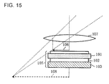
- Fig. 15 illustrates a conventional method of continuously displaying an enlarged image.
- light from a backlight 103 is uniformly emitted to a liquid crystal cell 101 through a light guide plate 102, so as to cause a liquid crystal display 105 to display an image 106 of, for example, an arrow shape.
- a convex lens 107 such as a loupe
- the image 106 enlarged to a virtual image 108 can be recognized.
- Fig. 16 depicts the principle of an image on a liquid crystal display and the enlarged image thereof. Over an image shown on the liquid crystal display 105, an enlarged image 111 having a larger display area is formed. In this case, the image of clouds above a mountain range displayed on the liquid crystal display 105 is recognized as the enlarged image 111.
- the method of employing the convex lens 107 to view the enlarged image of the image 106 as shown in Figs. 15 and 16 requires constantly carrying the convex lens 107 which is relatively heavy. Also, except for the case where the viewer is seated at a desk or a table, the viewer has to hold the information processing apparatus in one hand and the convex lens 107 in the other hand, when enlarging the image. In other words, both hands are occupied for viewing the enlarged image, which makes it impossible to, for example, use a hand to write down a memorandum while viewing the image. Besides, although the image is enlarged by the convex lens 107, the display panel such as the liquid crystal display displays the image as a set of each pixel. Accordingly, enlarging the image often results in merely viewing a coarser image. This is the same effect as what is known as ineffective enlargement, which does not achieve an increase in information despite the enlargement.
- the method that employs the convex lens 107 only enlarges the image itself, and not the image region. Besides, employing the convex lens 107 may incur drawbacks such as emergence of optical strain and chromatic aberration in the image.
- an exemplary object of the invention is to provide an image display device capable of displaying, on a single display panel, a larger image region than the display area of the display panel, and a method of displaying the image on such device.
- an image display device including a display panel that displays a sheet of image; a spatial region setting unit that defines a plurality of spatial regions where an image displayed on the display panel can be visually recognized from mutually different spatial positions; an image splitter that splits an image having a larger display area than the sheet of image corresponding to a display area of the display panel, into a plurality of sheets of images respectively corresponding to each of the plurality of spatial regions; and an image display unit that causes the display panel to display in a split manner the plurality of sheets of images in different display directions, such that each of the plurality of sheets of images split by the image splitter can be visually recognized from the corresponding one of the mutually different spatial positions.
- the plurality of spatial regions where the image displayed on the display panel can be visually recognized from different spatial positions is defined in advance by the spatial region setting unit, and the sheets of images split by the image splitter correspond to the respective spatial regions.
- the image display unit executes the control so as to cause the display panel to display in a split manner the sheets of images in different display directions, such that each sheet of image split by the image splitter can be visually recognized from the corresponding one of the mutually different spatial positions.
- each sheet of image split to be viewed from different directions may be displayed in parallel in a time-division manner, or one of the sheets of images may be selectively displayed according to the relative spatial position of the viewer's eye.
- the spatial regions may be switched by displacing the eye, or by rotating the display panel either horizontally or vertically.
- the display panel may be horizontally displaced so as to switch the spatial region to be displayed, for selectively viewing each display panel when the plurality of display panels is aligned on a plane.
- a method of displaying an image including: splitting an image having a larger display area than a sheet of image corresponding to a display area of a display panel, into a plurality of sheets of images respectively corresponding to each of a plurality of predetermined spatial regions; and sequentially selecting one of the sheets of images split in the image splitting step and corresponding to the spatial region designated for viewing among the plurality of spatial regions, and causing the display panel to display the selected image.
- an image having a larger area can be split and sequentially displayed, by splitting an image into a predetermined number of sheets in the image splitting step, to enable displaying the image in a larger region than the size of a single display panel, and sequentially selecting one of those images corresponding to the spatial region designated for viewing out of the plurality of spatial regions, to thereby display the selected image on the display panel.
- the method is applicable not only to a still image but also to a moving image.
- the image displayed on the display panel that displays a sheet of image can be switched according to the spatial region, which enables displaying an image having a larger display area than an image corresponding to the display area of the display panel, in a time-division manner. Accordingly, a small-sized device such as a mobile phone can still display a more extensive image, and therefore a small-sized, light-weighted and inexpensive image display device can be obtained. Moreover, there is no need to reduce the image area of the same image when displaying that image on the display panel, which eliminates the need to degrade the resolution of the image, thereby facilitating displaying high-quality images.
- Fig. 1 illustrates the appearance of a mobile phone including an image display device according to an exemplary embodiment of the present invention.
- an image displayed on a display panel 203 is switched to a plurality of images, as a user holding the mobile phone in a hand 201 changes the position of his/her eye 202.
- the boundaries between the plurality of images are continuous, and therefore the images displayed on the display panel 203 appear as a continuous image, allowing the user to recognize an image having a wide angle of view.
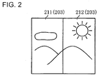
- Fig. 2 depicts an example of an image displayed on the display panel of the mobile phone according to this exemplary embodiment. It will be assumed here that two images are displayed on the display panel 203 according to the viewing position (spatial region).
- a first image 211 represents the image on the display panel 203 viewed from the user's eye 202L which is on (has moved to) the left side in Fig. 1
- a second image 212 represents the image on the display panel 203 viewed from the user's eye 202R which is on (has moved to) the right side in Fig. 1 .
- the images 211, 212 are alternately switched.
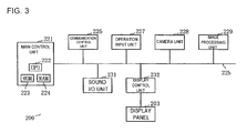
- Fig. 3 shows an outline of the circuit configuration of the mobile phone.
- the mobile phone 200 includes a main control unit 221 that executes the overall control of the mobile phone 200.
- the main control unit 221 includes a central processing unit (CPU) 222, a read only memory (ROM) 223 in which a control program is stored, and a random access memory (RAM) 224 serving as an operational memory.
- the main control unit 221 is connected to the respective units in the device via a signal transmitter 225 such as a bus.
- a communication control unit 226 controls the verbal communication with a wireless base station (not shown), and is also capable of executing other types of wireless communication such as infrared communication. Further, data communication can also be executed with an external party (not shown) through a universal serial bus (USB) port (not shown).
- An operation input unit 227 includes various keys shown in Fig. 1 , by which various data such as a dial number can be input.
- a camera unit 228 includes an imaging device such as a charge-coupled device (CCD), to thereby shoot a still image or a moving image.
- An image processing unit 229 serves to process an image shot by the camera unit 228, or an image input through the communication control unit 226.
- the image processing unit 229 also serves to split the image to be displayed on the display panel 203.
- a sound I/O unit 231 is engaged in inputting and outputting the voice for phone communication and outputting an alarm sound.
- a display control unit 232 is a circuit that drives the display panel 203.
- a part of the units except the main control unit 221, such as the communication control unit 226, may be realized as a software such that the CPU 222 executes the control program stored in the ROM 223.
- Fig. 4 illustrates a cross-sectional structure of the display panel according to the exemplary embodiment, and how the images are switched according to the position of the eye.
- the display panel 203 includes a liquid crystal display (LCD) panel 241 that displays an image with electrodes (not shown) aligned in a matrix form. Under the LCD panel 241, prism sheets 242 are aligned at a predetermined interval.
- the prism sheet 242 according to this exemplary embodiment is an optical component that switches the direction of a light beam in two directions, namely a first direction 243 and a second direction 244, and has one surface (lower surface in Fig. 4 ) serrated.
- the prism sheet 242 is commercially available from several manufacturers.
- Fig. 5 depicts the relationship between the two directions shown in Fig. 4 .
- the first direction 243 and the second direction 244 are symmetrical with respect to a line 251 which is perpendicular to the LCD panel 241, and both directions define an emission angle of ⁇ . It is not mandatory that these directions 243, 244 symmetrically define the incident angle, but it generally suffices that the two directions are different from each other.
- Fig. 4 willagain be referred to.
- reflection sheets 245 that reflect a light beam are located at a predetermined interval.
- a transparent light guide plate 246 is provided so as to transmit the light beam.
- one each of first LED group 247 is disposed vertically of the sheet with a spacing, so as to form the first image 211 shown in Fig. 2 .
- one each of second LED group 248 is likewise disposed vertically of the sheet with a spacing, so as to form the second image 212 shown in Fig. 2 .
- the LCD panel 241 alternately displays the first image 211 and the second image 212, at rates of 1/60 seconds each, for example.
- the first LED group 247 is turned on, so that the light of the relevant image is emitted in the first direction 243.
- the second LED group 248 is turned on, so that the light of the relevant image is emitted in the first direction 244.
- the image is viewed with only one eye.
- the eye 202L of the user in the left-hand spatial region in Fig. 4 can see the first image 211
- the eye 202R of the user in the right-hand spatial region in Fig. 4 can see the second image 212.
- the image is switched from the first image 211 to the second image 212, via a process that the brain recognizes the boundary of the two images as a continuous image.
- Such image recognition process of the brain is similar to the process executed to form a three-dimensional image when different images are shown to the left and the right eye.
- Fig. 6 indicates a display control process, based on an instruction to display a still image. Such display control is executed, for example, when the user utilizes a preview function to watch an image shot by the camera unit 228 shown in Fig. 3 , or views an image attached to a received e-mail.
- Fig. 3 will also be referred to for the description.
- step S301 When the user of the mobile phone 200 manipulates the operation input unit 227 so as to display an image, an instruction to retrieve the image is thereby generated inside the mobile phone (step S301).
- the main control unit 221 Upon receipt of the instruction (Y), the main control unit 221 stores the designated image in an appropriate memory (not shown) in the image processing unit 229 or in the RAM 224 for operation (step S302).
- the image is stored in a predetermined region of the RAM 224.
- the main control unit 221 checks whether the instruction of the user requests a normal display mode of displaying a sheet of image corresponding to the size of the display panel 203, or a large display mode of displaying an image corresponding to two sheets (step S303). If the large display mode is requested (Y), the image stored in the RAM 224 is split into the left and right portions (step S304). In this process, the image may be split such that the boundary portions slightly overlap, for easier matching of the image. As a result, in the RAM 224, for example the first image 211 and the second image 212 shown in Fig. 2 are independently stored.
- the main control unit 221 checks whether one of the first timing and the second timing, which alternate every 1/60 second, has been reached, and whether an instruction to stop the display has been generated (step S305 to step S307). If the first timing hasbeen reached (Y at step S305), the main control unit 221 reads out the first image 211 from the RAM 224, and at the same time turns on the first light emitting diode (LED) group 247 of the display control unit 232 (step S308). As a result, the first image 211 is displayed on the LCD panel 241 shown in Fig. 4 .
- LED light emitting diode
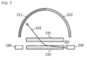
- Fig. 7 depicts the state when the first image is displayed on the display panel. Under this state, the first LED group 247 is on and the second LED group 248 is off. Accordingly, a light beam 261 output by the first LED group 247 is incident upon the prism sheet 242 directly, or after being reflected by the reflection sheet 245 shown in Fig. 4 and reciprocating in the transparent light guide plate 246. Then these light beams are emitted in the first direction 243. Therefore, if the eye 202L is present in the first direction 243 (Ref. Fig. 4 ), the eye 202L can view the first image 211. At this moment, the second image 212 is not formed. Accordingly, the second image 212 cannot be recognized at the position of the eye 202R (Ref. Fig. 4 ).
- Fig. 6 will be referred to again for the description.
- the main control unit 221 reads out the second image 212 from the RAM 224 when another 1/60 second has elapsed and the second timing hasbeen reached (Y at step S306), unless the instruction to stop the display is generated (N at step S307), and at the same time turns on the second LED group 248 of the display control unit 232 (step S309).
- the second image 212 is displayed on the LCD panel 241 shown in Fig. 4 .
- Fig. 8 depicts the state when the second image is displayed on the display panel. Under this state, the second LED group 248 is on and the first LED group 247 is off. Accordingly, a light beam 262 output by the second LED group 248 is incident upon the prism sheet 242 directly, or after being reflected by the reflection sheet 245 shown in Fig. 4 and reciprocating in the transparent light guide plate 246. Then these light beams are emitted in the second direction 244. Therefore, if the eye 202R is present in the second direction 244 (Ref. Fig. 4 ), the eye 202R can view the second image 212. At this moment, the first image 211 is not formed. Accordingly, the first image 211 cannot be recognized at the position of the eye 202L (Ref. Fig. 4 ).
- Fig. 6 will be referred to again for the description.
- the state after splitting the image at the step S304 is restored, after which the first image and the second image are repeatedly displayed every 1/60 second, until the instruction to stop displaying the image is generated (Y at step S307) in the mobile phone.
- the eye 202L, 202R moving to the left and the right recognizes the first image 211 and the second image 212 as a constantly present image, because of the afterimage effect.
- the single display panel 203 can display the image in a twice as large visual field area. If the instruction to stop the display is generated at the step S307 (Y), the display is finished (End).
- a display control employed in an image display device of a popular mobile phone or the like is executed (step S310).
- the image is adjusted to the size corresponding to the display panel 203, for being displayed.
- the image does not have to be switched.
- the first LED group 247 and the second LED group 248 are both turned on, so that the user views a sheet of image from a wider angle range.
- the display is finished (End) when the instruction to stop the display is generated (Y at step S311).
- Fig. 9 illustrates an essential portion of an optical system according to a first variation of the present invention.
- This variation employs a light guide plate 401, which corresponds to the light guide plate 246 ( Fig. 4 ) of the foregoing exemplary embodiment, and which serves to switch the direction of a light beam in two directions according to the incident angle.
- the light guide plate 401 is provided, on one of the lateral faces 402, with first light emitting diodes 403 that emit light so as to make it incident upon the light guide plate 401 substantially orthogonally to the lateral face 402, and second light emitting diodes 405 that emit light in a direction rotated by a predetermined angle from the incident angle of the first light emitting diode 403 within a plane parallel to the output surface 404 of the light guide plate 401, the first light emitting diodes 403 and the second light emitting diodes 405 being alternately aligned lengthwise of the lateral face 402, at regular intervals.
- the light guide plate 401 of the first variation emits the light incident thereon from the first light emitting diode 403, in a first direction 411 inclined by a predetermined angle from the output surface 404 of the light guide plate, and emits the light incident thereon from the second light emitting diode 405 in a second direction 412 which is perpendicular to the output surface 404 of the light guide plate.
- the second direction 412 does not necessarily have to be perpendicular to the output surface 404, but it suffices that the second direction 412 is different from the first direction 411.
- the light thus split into the first direction 411 and the second direction 412 is incident on a sheet or a flat plate similar to the prism sheet 242 of the exemplary embodiment, to be thereby converted into the first direction 243 and the second direction 244 shown in Fig. 4 of the exemplary embodiment. Accordingly, turning on the first light emitting diode 403 in synchronization with the first image 211 described in the exemplary embodiment, and the second light emitting diode 405 in synchronization with the first image 212, at an image switching speed sufficient for producing an afterimage enables displaying the image under the condition that the single display panel 203 substantially has a twice as large visual field area.
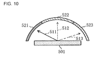
- Fig. 10 depicts an essential portion of an optical system according to a second variation of the present invention.
- the direction of the light beam is switched from a first direction 511 to a third direction 513 in a direction change sheet similar to the prism sheet 242 of the exemplary embodiment, to be output therefrom.
- a first image 521 to a third image 523 are respectively displayed within a timing that produces an afterimage.
- Fig. 11 illustrates a state when an image of a cloud and the moon above a mountain range is displayed according to the second variation. Since the first to the third image sequentially appears according to the viewing position, the user of the mobile phone can recognize an image corresponding to three display panels sequentially and horizontally connected. Naturally the image that can be viewed at a time is of the size of a single display panel 203, however as the user shifts the eye position the display area of the image is expanded to substantially three times as large.
- the image display in the normal display mode may be performed by outputting the light beam in all of the first direction 511 to the third direction 513, or by outputting only the central light beam in the second direction 512.
- the visual field range that provides a clear view of the display panel 203 is narrowed. Accordingly, for example, when the user is in a train and would not like the person on the adjacent seat to see the image, it is appropriate to output only the light beam in the second direction 512.
- selecting the direction in which the light beam is to be output allows adjusting the range of the angle of view.
- FIG. 12 shows an outline of the circuit configuration of a mobile phone according to a third variation of the present invention.
- a mobile phone 200C according to this variation further includes a horizontal angle detector 601 in addition to the structure of the mobile phone 200 according to the foregoing exemplary embodiment.
- the horizontal angle detector 601 serves to detect whether the display panel of the mobile phone 200C is substantially horizontal or inclined, so as to switch the image to be displayed on the display panel 203 according to three detected angles.
- a main control unit 221C has the same configuration as the main control unit 221 according to the embodiment, a ROM 223C stores therein a control program designed for the mobile phone 200C of this variation.
- the horizontal angle detector 601 may be embodied with various sensors that can detect inclination.
- Fig. 13 indicates a display process in the large display mode according to the third variation. It will be assumed that the image to be displayed at the step S302 of Fig. 6 is stored in the memory. Under such state, the main control unit 221C decides whether the large display mode has been selected (step S701). In the case of the normal display mode (N), the process according to step S310 and thereafter in Fig. 6 is performed, and hence the drawings and the description will not be repeated.
- the horizontal angle detector 601 decides whether the display panel is substantially horizontally retained (step S703).
- substantially horizontal refers to a state when the front side of the user's face and the display panel 203 are substantially parallel. Accordingly, the term includes the state when the display panel 203 is substantially horizontally oriented literally, and when the user retains the mobile phone 200C by hand such that the display panel is inclined forward for comfortably viewing. In both those states, the user is looking at the display panel in front of his/her face.
- the LED group that outputs the light beam in the second direction 512 in Fig. 10 is turned on, and under such a state the second image 522 is read out from the corresponding memory region, and displayed (step S704).
- the display of the second image 522 is continued as long as the horizontal angle detector 601 detects that the display panel is substantially horizontal, and unless the instruction to stop the display is generated (N at step S705).
- the user When the user wishes to view the image extending to the left of the second image 522 being displayed, the user slightly rotates the mobile phone 200C in his/her hand clockwise, so that the left-side edge of the display panel 203 moves away from the user, from the frontal orientation.
- the horizontal angle detector 601 resultantly detects the rotation (Y at step S706)
- the main control unit 221C turns on the LED group that outputs the light beam in the first direction 511 instead, and under such state the first image 521 is read out from the corresponding memory region, and displayed (step S707).
- the display of the first image 521 is continued as long as the horizontal angle detector 601 detects the state where the display panel is inclined clockwise, and unless the instruction to stop the display is generated (N at step S705).
- the user when the user wishes to view the image extending to the right of the second image 522 currently displayed, the user slightly rotates the mobile phone 200C in his/her hand counterclockwise, opposite to the clockwise direction.
- the main control unit 221C turns on the LED group that outputs the light beam in the third direction 513 instead, and under such state the third image 523 is read out from the corresponding memory region, and displayed (step S708).
- the display of the third image 523 is continued as long as the horizontal angle detector 601 detects the state when the display panel is inclined counterclockwise, and unless the instruction to stop the display is generated (N at step S705).
- the user can sequentially switch the spatial region so as to recognize the three images as if being a sheet of continuous image, simply by rotating the mobile phone 200C such that an edge portion of the display panel 203 moves away and the other edge portion thereof comes closer, instead of moving his/her face.
- the images corresponding to the respective spatial positions do not have to be displayed so as to create the afterimage, which leads to reduced power consumption.
- the images can still be switched by the rotation with the same structure of the mobile phone as the foregoing exemplary embodiment, without incorporating the horizontal angle detector 601.
- the display can be switched to images corresponding to two or three, or a larger number of display panels, by moving the display panel 203 to the left and the right from the frontal position, instead of rotating the mobile phone 200C as above.
- the first image 521 is displayed on the display panel 203
- the third image 523 is displayed on the display panel 203.
- the movement direction can be detected, for example in the case where the camera unit 223 is located on the same side of the mobile phone 200C as the display panel, by distinguishing with the camera in which direction the user's face, being the photographic subject, is shifted.
- an acceleration sensor can also be employed for distinguishing the moving direction.
- Fig. 14 indicates a display process of a moving image in the large display mode according to a fourth variation of the present invention.
- the moving image is to be reproduced with the same hardware as that of the foregoing exemplary embodiment.
- the process enters a standby mode for a first timing to display the first image (step S805).
- the first image split into two portions and stored in the memory regions at the step S804, is read out.
- the first LED group 247 is turned on (step S806).
- the first LED group 247 is turned on and the light of the image is output in the first direction 243.
- step S807 the process enters the standby mode for a second timing to display the second image.
- the second image split into two portions and stored in the memory regions at the step S804, is read out.
- the second LED group 247 is turned on (step S808).
- the first LED group 247 is turned on and the light of the image is output in the first direction 243.
- step S809 When the image of the first frame is thus displayed in the size corresponding to two display panels, it is checked whether the instruction to stop the display process of the moving image in the large display mode has been generated, either by reaching the end of the moving image or by the user's instruction (step S809). If the instruction to stop the display process of the moving image in the large display mode has not been generated (N), the parameter "m" is increased by 1, and the process returns to the step S803. In other words, in this case the "m” is set as "2" and the process returns to the step S803, so that the image of the second frame is retrieved. Thereafter, a similar process to the above is performed. When it is confirmed that the instruction to stop the display is generated at the step S809, the display process is finished (End).
- each frame that constitutes the moving image is sequentially read out, so that the moving image is reproduced such that the image corresponding to two display panels is continuously recognized, as in the case of the still image according to the foregoing exemplary embodiment.
- the display process of the moving image in the normal display mode is performed.
- the fourth variation describes the reproduction of the moving image corresponding to two display panels, it is equally possible to reproduce the moving image corresponding to three display panels.
- the image display in the large display mode is performed based on viewing with one eye, however this is not the only form.
- the present invention can likewise be applied.
- the exemplary embodiment represents the case when the present invention is applied to the image display device of the mobile phone, it is a matter of course that the present invention is applicable to all such devices that display an image, except those equipped with a very large-scaled display panel.
Landscapes
- Physics & Mathematics (AREA)
- Nonlinear Science (AREA)
- Mathematical Physics (AREA)
- Chemical & Material Sciences (AREA)
- Crystallography & Structural Chemistry (AREA)
- General Physics & Mathematics (AREA)
- Optics & Photonics (AREA)
- Control Of Indicators Other Than Cathode Ray Tubes (AREA)
- Liquid Crystal (AREA)
- Liquid Crystal Display Device Control (AREA)
Applications Claiming Priority (2)
| Application Number | Priority Date | Filing Date | Title |
|---|---|---|---|
| JP2006090851 | 2006-03-29 | ||
| PCT/JP2007/000303 WO2007111022A1 (ja) | 2006-03-29 | 2007-03-27 | 画像表示装置および画像表示方法 |
Publications (3)
| Publication Number | Publication Date |
|---|---|
| EP2001010A2 true EP2001010A2 (de) | 2008-12-10 |
| EP2001010A9 EP2001010A9 (de) | 2009-03-18 |
| EP2001010A4 EP2001010A4 (de) | 2012-06-20 |
Family
ID=38540957
Family Applications (1)
| Application Number | Title | Priority Date | Filing Date |
|---|---|---|---|
| EP07736960A Withdrawn EP2001010A4 (de) | 2006-03-29 | 2007-03-27 | Bildanzeigeeinrichtung und bildanzeigeverfahren |
Country Status (5)
| Country | Link |
|---|---|
| US (1) | US8139084B2 (de) |
| EP (1) | EP2001010A4 (de) |
| JP (1) | JPWO2007111022A1 (de) |
| CN (1) | CN101416232B (de) |
| WO (1) | WO2007111022A1 (de) |
Families Citing this family (5)
| Publication number | Priority date | Publication date | Assignee | Title |
|---|---|---|---|---|
| JP5413688B2 (ja) * | 2011-02-16 | 2014-02-12 | ブラザー工業株式会社 | 画像区画プログラム、及び、表示装置 |
| US9047692B1 (en) * | 2011-12-20 | 2015-06-02 | Google Inc. | Scene scan |
| KR101619651B1 (ko) * | 2014-11-26 | 2016-05-10 | 현대자동차주식회사 | 운전자 감시장치 및 그의 조명제어방법 |
| US20170010407A1 (en) * | 2015-07-09 | 2017-01-12 | Apple Inc. | Displays With Multimode Backlight Units |
| CN112817175A (zh) | 2016-11-03 | 2021-05-18 | 3M创新有限公司 | 具有非对称转向膜的多路复用背光源 |
Family Cites Families (10)
| Publication number | Priority date | Publication date | Assignee | Title |
|---|---|---|---|---|
| JPH10224820A (ja) | 1997-02-07 | 1998-08-21 | Canon Inc | 複眼カメラ装置 |
| US7210836B2 (en) * | 2002-09-19 | 2007-05-01 | Mitsubishi Denki Kabushiki Kaisha | Display unit and electronic apparatus with display unit |
| NZ521505A (en) * | 2002-09-20 | 2005-05-27 | Deep Video Imaging Ltd | Multi-view display |
| JP2004144822A (ja) | 2002-10-22 | 2004-05-20 | Nec Corp | 大画面表示装置及び大画面表示方法 |
| JP2005024737A (ja) * | 2003-06-30 | 2005-01-27 | Optrex Corp | 液晶表示装置およびその表示方法 |
| GB2405546A (en) * | 2003-08-30 | 2005-03-02 | Sharp Kk | Dual view directional display providing images having different angular extent. |
| US7777764B2 (en) * | 2003-09-11 | 2010-08-17 | Sharp Kabushiki Kaisha | Portable display device |
| JP4671591B2 (ja) * | 2003-09-12 | 2011-04-20 | シャープ株式会社 | 情報処理装置 |
| JP3908241B2 (ja) * | 2004-06-24 | 2007-04-25 | オリンパス株式会社 | 映像表示装置 |
| JP2006041795A (ja) * | 2004-07-26 | 2006-02-09 | Canon Inc | 画像表示装置 |
-
2007
- 2007-03-27 CN CN2007800124214A patent/CN101416232B/zh not_active Expired - Fee Related
- 2007-03-27 US US12/294,277 patent/US8139084B2/en active Active
- 2007-03-27 JP JP2008507374A patent/JPWO2007111022A1/ja active Pending
- 2007-03-27 EP EP07736960A patent/EP2001010A4/de not_active Withdrawn
- 2007-03-27 WO PCT/JP2007/000303 patent/WO2007111022A1/ja not_active Ceased
Also Published As
| Publication number | Publication date |
|---|---|
| WO2007111022A1 (ja) | 2007-10-04 |
| CN101416232A (zh) | 2009-04-22 |
| EP2001010A9 (de) | 2009-03-18 |
| US8139084B2 (en) | 2012-03-20 |
| JPWO2007111022A1 (ja) | 2009-08-06 |
| CN101416232B (zh) | 2011-03-23 |
| EP2001010A4 (de) | 2012-06-20 |
| US20090251408A1 (en) | 2009-10-08 |
Similar Documents
| Publication | Publication Date | Title |
|---|---|---|
| JP6724987B2 (ja) | 制御装置および検出方法 | |
| US9213403B1 (en) | Methods to pan, zoom, crop, and proportionally move on a head mountable display | |
| US7059733B2 (en) | Display apparatus | |
| WO2018003860A1 (ja) | 表示装置、プログラム、表示方法および制御装置 | |
| US12032174B2 (en) | Steerable hybrid display using a waveguide | |
| CN103765879A (zh) | 扩展激光深度图范围的方法 | |
| EP2001010A2 (de) | Bildanzeigeeinrichtung und bildanzeigeverfahren | |
| JP2001189902A (ja) | ヘッドマウンテッドディスプレイ制御方法及びヘッドマウンテッドディスプレイ装置 | |
| KR102269833B1 (ko) | 스마트 안경 | |
| JP2012070081A (ja) | 画像表示装置、画像表示プログラム及び画像表示システム | |
| US20140293020A1 (en) | Display device | |
| JP2009104429A (ja) | ヘッドマウントディスプレイ装置及び携帯装置 | |
| CA3076108A1 (en) | Method to help navigate users of mobile devices by re-directed camera views | |
| CN116125669A (zh) | 显示装置及拍摄视野的调制方法 | |
| JP2021056371A (ja) | 表示システム、表示方法及び表示プログラム | |
| US12147608B2 (en) | Computing system with head wearable display | |
| KR20070009207A (ko) | 가상 키보드 입력 장치를 갖는 이동통신 단말기 및 이를이용한 입력 방법 | |
| EP1731959A1 (de) | Stereoskopische, zweidimensionale bildanzeigeeinheit | |
| JPWO2004099965A1 (ja) | 画像表示方法及び装置 | |
| JP2017079389A (ja) | 表示装置、表示装置の制御方法、及び、プログラム | |
| KR102151206B1 (ko) | 이동 단말기 및 그 제어방법 | |
| CN119678119A (zh) | 信息处理装置以及信息处理方法 | |
| JP2008116791A (ja) | 電子書籍装置のページめくり方法 | |
| JPH07104233A (ja) | 原稿投影装置 | |
| CN121569335A (zh) | 空中悬浮影像显示装置、便携终端和显示方法 |
Legal Events
| Date | Code | Title | Description |
|---|---|---|---|
| PUAI | Public reference made under article 153(3) epc to a published international application that has entered the european phase |
Free format text: ORIGINAL CODE: 0009012 |
|
| 17P | Request for examination filed |
Effective date: 20080923 |
|
| AK | Designated contracting states |
Kind code of ref document: A2 Designated state(s): DE FR GB IT |
|
| PUAB | Information related to the publication of an a document modified or deleted |
Free format text: ORIGINAL CODE: 0009199EPPU |
|
| DAX | Request for extension of the european patent (deleted) | ||
| RBV | Designated contracting states (corrected) |
Designated state(s): DE FR GB IT |
|
| A4 | Supplementary search report drawn up and despatched |
Effective date: 20120521 |
|
| RIC1 | Information provided on ipc code assigned before grant |
Ipc: G02F 1/13357 20060101ALI20120514BHEP Ipc: G02F 1/133 20060101ALI20120514BHEP Ipc: G09G 3/36 20060101AFI20120514BHEP Ipc: G09G 3/20 20060101ALI20120514BHEP Ipc: G09G 3/34 20060101ALI20120514BHEP Ipc: G02B 6/00 20060101ALI20120514BHEP |
|
| REG | Reference to a national code |
Ref country code: NO Ref legal event code: CHAD Owner name: ZOETIS LLC, US |
|
| RAP1 | Party data changed (applicant data changed or rights of an application transferred) |
Owner name: LENOVO INNOVATIONS LIMITED (HONG KONG) |
|
| 17Q | First examination report despatched |
Effective date: 20150810 |
|
| STAA | Information on the status of an ep patent application or granted ep patent |
Free format text: STATUS: THE APPLICATION IS DEEMED TO BE WITHDRAWN |
|
| 18D | Application deemed to be withdrawn |
Effective date: 20171003 |