EP1999304B2 - Solution spun fiber process - Google Patents
Solution spun fiber process Download PDFInfo
- Publication number
- EP1999304B2 EP1999304B2 EP07753736.3A EP07753736A EP1999304B2 EP 1999304 B2 EP1999304 B2 EP 1999304B2 EP 07753736 A EP07753736 A EP 07753736A EP 1999304 B2 EP1999304 B2 EP 1999304B2
- Authority
- EP
- European Patent Office
- Prior art keywords
- spinning solution
- polymers
- nozzle
- collector
- rotary sprayer
- Prior art date
- Legal status (The legal status is an assumption and is not a legal conclusion. Google has not performed a legal analysis and makes no representation as to the accuracy of the status listed.)
- Active
Links
- 239000000835 fiber Substances 0.000 title claims description 73
- 238000000034 method Methods 0.000 title claims description 27
- 238000009987 spinning Methods 0.000 claims description 45
- 229920000642 polymer Polymers 0.000 claims description 28
- 230000005684 electric field Effects 0.000 claims description 21
- 239000002904 solvent Substances 0.000 claims description 17
- 238000007493 shaping process Methods 0.000 claims description 16
- 239000012530 fluid Substances 0.000 claims description 11
- 229920001634 Copolyester Polymers 0.000 claims description 3
- 229920000106 Liquid crystal polymer Polymers 0.000 claims description 3
- 239000004977 Liquid-crystal polymers (LCPs) Substances 0.000 claims description 3
- 239000004952 Polyamide Substances 0.000 claims description 3
- 239000004793 Polystyrene Substances 0.000 claims description 3
- 229920003235 aromatic polyamide Polymers 0.000 claims description 3
- 229920013724 bio-based polymer Polymers 0.000 claims description 3
- 229920002988 biodegradable polymer Polymers 0.000 claims description 3
- 239000004621 biodegradable polymer Substances 0.000 claims description 3
- 229920001577 copolymer Polymers 0.000 claims description 3
- 229920002313 fluoropolymer Polymers 0.000 claims description 3
- 239000004811 fluoropolymer Substances 0.000 claims description 3
- 229920005615 natural polymer Polymers 0.000 claims description 3
- 229920000233 poly(alkylene oxides) Polymers 0.000 claims description 3
- 229920001281 polyalkylene Polymers 0.000 claims description 3
- 229920002647 polyamide Polymers 0.000 claims description 3
- 229920000728 polyester Polymers 0.000 claims description 3
- 229920000193 polymethacrylate Polymers 0.000 claims description 3
- 229920002223 polystyrene Polymers 0.000 claims description 3
- 229920002635 polyurethane Polymers 0.000 claims description 3
- 239000004814 polyurethane Substances 0.000 claims description 3
- 102000004169 proteins and genes Human genes 0.000 claims description 3
- 108090000623 proteins and genes Proteins 0.000 claims description 3
- 229920001169 thermoplastic Polymers 0.000 claims description 3
- 229920006163 vinyl copolymer Polymers 0.000 claims description 3
- 229920002554 vinyl polymer Polymers 0.000 claims description 3
- -1 poly(ethylene oxide) Polymers 0.000 description 13
- 238000001878 scanning electron micrograph Methods 0.000 description 11
- 239000007789 gas Substances 0.000 description 6
- 229920003171 Poly (ethylene oxide) Polymers 0.000 description 5
- 239000002121 nanofiber Substances 0.000 description 4
- 239000002131 composite material Substances 0.000 description 3
- 238000004519 manufacturing process Methods 0.000 description 3
- 229910052751 metal Inorganic materials 0.000 description 3
- 239000002184 metal Substances 0.000 description 3
- 239000003973 paint Substances 0.000 description 3
- 229920002451 polyvinyl alcohol Polymers 0.000 description 3
- 229910001220 stainless steel Inorganic materials 0.000 description 3
- 239000010935 stainless steel Substances 0.000 description 3
- FAPWRFPIFSIZLT-UHFFFAOYSA-M Sodium chloride Chemical compound [Na+].[Cl-] FAPWRFPIFSIZLT-UHFFFAOYSA-M 0.000 description 2
- 230000004888 barrier function Effects 0.000 description 2
- 230000007547 defect Effects 0.000 description 2
- 238000009826 distribution Methods 0.000 description 2
- 239000000463 material Substances 0.000 description 2
- 238000010998 test method Methods 0.000 description 2
- 238000009834 vaporization Methods 0.000 description 2
- 230000008016 vaporization Effects 0.000 description 2
- XLYOFNOQVPJJNP-UHFFFAOYSA-N water Substances O XLYOFNOQVPJJNP-UHFFFAOYSA-N 0.000 description 2
- 239000004809 Teflon Substances 0.000 description 1
- 229920006362 Teflon® Polymers 0.000 description 1
- 230000015572 biosynthetic process Effects 0.000 description 1
- 239000011248 coating agent Substances 0.000 description 1
- 238000000576 coating method Methods 0.000 description 1
- 238000001523 electrospinning Methods 0.000 description 1
- 238000004626 scanning electron microscopy Methods 0.000 description 1
- 239000011780 sodium chloride Substances 0.000 description 1
- GOZDTZWAMGHLDY-UHFFFAOYSA-L sodium picosulfate Chemical compound [Na+].[Na+].C1=CC(OS(=O)(=O)[O-])=CC=C1C(C=1N=CC=CC=1)C1=CC=C(OS([O-])(=O)=O)C=C1 GOZDTZWAMGHLDY-UHFFFAOYSA-L 0.000 description 1
Images

Classifications
-
- D—TEXTILES; PAPER
- D01—NATURAL OR MAN-MADE THREADS OR FIBRES; SPINNING
- D01D—MECHANICAL METHODS OR APPARATUS IN THE MANUFACTURE OF ARTIFICIAL FILAMENTS, THREADS, FIBRES, BRISTLES OR RIBBONS
- D01D5/00—Formation of filaments, threads, or the like
- D01D5/18—Formation of filaments, threads, or the like by means of rotating spinnerets
-
- D—TEXTILES; PAPER
- D01—NATURAL OR MAN-MADE THREADS OR FIBRES; SPINNING
- D01D—MECHANICAL METHODS OR APPARATUS IN THE MANUFACTURE OF ARTIFICIAL FILAMENTS, THREADS, FIBRES, BRISTLES OR RIBBONS
- D01D5/00—Formation of filaments, threads, or the like
- D01D5/11—Flash-spinning
-
- B—PERFORMING OPERATIONS; TRANSPORTING
- B29—WORKING OF PLASTICS; WORKING OF SUBSTANCES IN A PLASTIC STATE IN GENERAL
- B29C—SHAPING OR JOINING OF PLASTICS; SHAPING OF MATERIAL IN A PLASTIC STATE, NOT OTHERWISE PROVIDED FOR; AFTER-TREATMENT OF THE SHAPED PRODUCTS, e.g. REPAIRING
- B29C48/00—Extrusion moulding, i.e. expressing the moulding material through a die or nozzle which imparts the desired form; Apparatus therefor
- B29C48/03—Extrusion moulding, i.e. expressing the moulding material through a die or nozzle which imparts the desired form; Apparatus therefor characterised by the shape of the extruded material at extrusion
- B29C48/05—Filamentary, e.g. strands
-
- D—TEXTILES; PAPER
- D01—NATURAL OR MAN-MADE THREADS OR FIBRES; SPINNING
- D01D—MECHANICAL METHODS OR APPARATUS IN THE MANUFACTURE OF ARTIFICIAL FILAMENTS, THREADS, FIBRES, BRISTLES OR RIBBONS
- D01D5/00—Formation of filaments, threads, or the like
-
- D—TEXTILES; PAPER
- D01—NATURAL OR MAN-MADE THREADS OR FIBRES; SPINNING
- D01D—MECHANICAL METHODS OR APPARATUS IN THE MANUFACTURE OF ARTIFICIAL FILAMENTS, THREADS, FIBRES, BRISTLES OR RIBBONS
- D01D5/00—Formation of filaments, threads, or the like
- D01D5/0007—Electro-spinning
- D01D5/0015—Electro-spinning characterised by the initial state of the material
- D01D5/003—Electro-spinning characterised by the initial state of the material the material being a polymer solution or dispersion
- D01D5/0038—Electro-spinning characterised by the initial state of the material the material being a polymer solution or dispersion the fibre formed by solvent evaporation, i.e. dry electro-spinning
-
- D—TEXTILES; PAPER
- D01—NATURAL OR MAN-MADE THREADS OR FIBRES; SPINNING
- D01D—MECHANICAL METHODS OR APPARATUS IN THE MANUFACTURE OF ARTIFICIAL FILAMENTS, THREADS, FIBRES, BRISTLES OR RIBBONS
- D01D5/00—Formation of filaments, threads, or the like
- D01D5/0007—Electro-spinning
- D01D5/0061—Electro-spinning characterised by the electro-spinning apparatus
- D01D5/0069—Electro-spinning characterised by the electro-spinning apparatus characterised by the spinning section, e.g. capillary tube, protrusion or pin
Definitions
- This invention relates to a process for forming fibers and fibrous webs.
- very fine fibers can be made and collected into a fibrous web useful for selective barrier end uses such as filters, battery separators, and breathable medical gowns.
- Rotary sprayers used in conjunction with a shaping fluid and an electrical field are useful in atomizing paint for coating a target device.
- the centrifugal force supplied by the rotary sprayers produces enough shear to cause the paint to become atomized and the shaping fluid and electrical field draw the atomized paint to the target device.
- This process has been optimized for the production of atomized droplets. Defects occur when too many atomized droplets agglomerate into larger entities.
- the prior art teaches toward making atomized droplets and not larger entities.
- the present invention provides a high throughput process to make very fine fibers and uniform webs by the use of a high speed rotary sprayer.
- the present invention is directed to a fiber forming process comprising the steps of supplying a spinning solution having at least one polymer dissolved in at least one solvent to a rotary sprayer having a rotating conical nozzle, the nozzle having a concave inner surface and a forward surface discharge edge; issuing the spinning solution from the rotary sprayer along the concave inner surface so as to distribute said spinning solution toward the forward surface of the discharge edge of the nozzle; and forming separate fibrous streams from the spinning solution while the solvent vaporizes to produce polymeric fibers in the absence of an electrical field, and a shaping fluid flows around the nozzle to direct the spinning solution away from the rotary sprayer.
- the fibers can be collected onto a collector to form a fibrous web.
- the present invention is directed to a fiber forming process comprising the steps of supplying a spinning solution having at least one polymer dissolved in at least one solvent to a rotary sprayer having a rotating conical nozzle, the nozzle having a concave inner surface and a forward surface discharge edge; issuing the spinning solution from the rotary sprayer along the concave inner surface so as to distribute said spinning solution toward the forward surface of the discharge edge of the nozzle; and forming separate fibrous streams from the spinning solution while the solvent vaporizes to produce polymeric fibers in the presence of an electrical field, and a shaping fluid flows around the nozzle to direct the spinning solution away from the rotary sprayer.
- the fibers can be collected onto a collector to form a fibrous web.
- the invention relates to a process for forming fibers from a spinning solution utilizing a rotary sprayer.
- the spinning solution comprises at least one polymer dissolved in at least one solvent. Any fiber forming polymer able to dissolve in a solvent that can be vaporized can be used. Suitable polymers include polyalkylene oxides, poly(meth)acrylates, polystyrene based polymers and copolymers, vinyl polymers and copolymers, fluoropolymers, polyesters and copolyesters, polyurethanes, polyalkylenes, polyamides, polyaramids, thermoplastic polymers, liquid crystal polymers, engineering polymers, biodegradable polymers, bio-based polymers, natural polymers, and protein polymers.
- the spinning solution can have a polymer concentration of about 1 % to about 90% by weight of polymer in the spinning solution. Also, in order to assist the spinning of the spinning solution, the spinning solution can be heated or cooled. Generally, a spinning solution with a viscosity from about 10 cP to about 100,000 cP is useful.
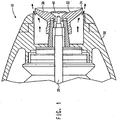
- FIG. 1 is an illustration of a nozzle portion of a rotary sprayer 10 suitable for forming fibers from the spinning solution.
- a spinning solution is prepared by dissolving one or more polymers in one or more solvents.
- the spinning solution is pumped through a supply tube 20 running axially through the rotary sprayer 10.
- the throughput rate of the solution is from about 1 cc/min to about 500 cc/min.
- a rotational speed of conical nozzle 30 is between about 10,000 rpm and about 100,000 rpm.
- the conical nozzle 30 can be any conical-like shape having a generally concave inner surface, including a bell shape such as illustrated here, a cup shape or even a frusto-conical shape.
- the shape of the nozzle's concave inner surface 32 can influence the production of fibers.
- the cross section of the nozzle's concave inner surface 32 can be straight or curved.
- the shape of the nozzle's forward surface discharge edge 34 can also influence the production of fibers.
- the nozzle's forward surface discharge edge 34 can be sharp or rounded and can include serrations or dividing ridges.
- a distributor disk 40 can be used to help direct the spinning solution from the supply tube 20 to the inner concave surface 32 of nozzle 30.
- the rotation speed of the nozzle propels the spinning solution along the nozzle's concave inner surface 32 and past the nozzle's forward surface discharge edge 34 to form separate fibrous streams, which are thrown off the discharge edge by centrifugal force. Simultaneously, the solvent vaporizes until fibers of the invention are formed.
- the fibers can be collected on a collector (not shown) to form a fibrous web.
- Figure 1 shows shaping fluid housing 50 which guides shaping fluid (marked by arrows) around nozzle 30 to direct the spinning solution away from the rotary sprayer 10.
- the shaping fluid can be a gas.
- gases and at various temperatures can be used to decrease or to increase the rate of solvent vaporization to affect the type of fiber that is produced.
- the shaping gas can be heated or cooled in order to optimize the rate of solvent vaporization.
- a suitable gas to use is air, but any other gas which does not detrimentally affect the formation of fibers can be used.
- an electrical field can be added to the process.
- a voltage potential can be added between the rotary sprayer and the collector. Either the rotary sprayer or the collector can be charged with the other component substantially grounded or they can both be charged so long as a voltage potential exists between them.
- an electrode can be positioned between the rotary sprayer and the collector wherein the electrode is charged so that a voltage potential is created between the electrode and the rotary sprayer and/or the collector.
- the electrical field has a voltage potential of about 1 kV to about 150 kV. Surprisingly, the electrical field seems to have little effect on the average fiber diameter, but does help the fibers to separate and travel toward a collector so as to produce a more uniform fibrous web.
- This process can make very fine fibers, preferably continuous fibers, with an average fiber diameter of less than 1,000 nm and more preferably from about 100 nm to 500 nm.
- the fibers can be collected on a collector into a fibrous web.
- the collector can be conductive for creating an electrical field between it and the rotary sprayer or an electrode.
- the collector can also be porous to allow the use of a vacuum device to pull vaporized solvent and optionally shaping gas away from the fibers and help pin the fibers to the collector to make the fibrous web.
- a scrim material can be placed on the collector to collect the fiber directly onto the scrim thereby making a composite material.
- a spunbond nonwoven can be placed on the collector and the fiber deposited onto the spunbond nonwoven. In this way composite nonwoven materials can be produced.
- Viscosity was measured on a Thermo RheoStress 600 rheometer equipped with a 20 mm parallel plate. Data was collected over 4 minutes with a continuous shear rate ramp from 0 to 1,000 s-1 at 23°C and reported in cP at 10 s-1.
- Fiber Diameter was determined as follows. Ten scanning electron microscope (SEM) images at 5,000x magnification were taken of each nanofiber layer sample. The diameter of eleven (11) clearly distinguishable nanofibers were measured from each SEM image and recorded. Defects were not included (i.e., lumps of nanofibers, polymer drops, intersections of nanofibers). The average fiber diameter for each sample was calculated and reported in nanometers (nm).
- Example 1 describes making a poly(ethylene oxide) continuous fiber without the use of an electrical field.
- Example 2 describes making a poly(ethylene oxide) continuous fiber with the use of an electrical field.
- Example 3 describes making a poly(vinyl alcohol) continuous fiber with the use of an electrical field.
- Continuous fibers were made using a standard Aerobell rotary atomizer and control enclosure for high voltage, turbine speed and shaping air control from ITW Automotive Finishing Group.
- the bell-shaped nozzle used was an ITW Ransburg part no. LRPM4001-02.
- a spinning solution of 10.0% poly(ethylene oxide) viscosity average molecular weight (Mv) of about 300,000, 0.1% sodium chloride, and 89.9% water by weight was mixed until homogeneous and poured into a Binks 83C-220 pressure tank for delivery to the rotary atomizer through the supply tube.
- the pressure on the pressure tank was set to a constant 15 psi. This produced a flow rate of about 2 cc/min.
- the shaping air was set at a constant 30 psi.
- the bearing air was set at a constant 95 psi.
- the turbine speed was set to a constant 40,000 rpm. No electrical field was used during this test.
- Fibers were collected on a Reemay nonwoven collection screen that was held in place 10 inches away from the bell-shaped nozzle by stainless steel sheet metal.
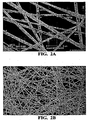
- the fiber size was measured from an image using scanning electron microscopy (SEM) and determined to be in the range of 100 nm to 500 nm, with an average fiber diameter of about 415 nm.
- SEM image of the fibers can be seen in Figure 2a.
- Fig. 2b is a SEM image which shows the distribution of the fibers spun according to this Example on the Reemay scrim.
- Example 2 was prepared similarly to Example 1, except an electrical field was applied.
- the electrical field was applied directly to the rotary atomizer by attaching a high voltage cable to the high voltage lug on the back of the rotary atomizer.
- the rotary atomizer was completely isolated from ground using a large Teflon stand so that the closest ground to the bell-shaped nozzle was the stainless steel sheet metal backing the Reemay collection belt.
- a +50 kV power supply was used in current control mode and the current was set to 0.02 mA.
- the high voltage ran at about 35 kV.
- the lay down of the fiber was much better than in Example 1 in that the coverage was very uniform over the collection area.
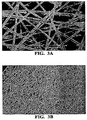
- the fiber size was measured from an image using SEM and determined to be in the range of 100 nm to 500 nm, with an average fiber diameter of about 350 nm.
- An SEM image of the fibers can be seen in Figure 3a.
- Fig. 3b is a SEM image which shows the distribution of the fibers spun according to this Example on the Reemay scrim.
- Continuous fibers were made using a 65 mm "Eco Bell” serrated bell-shaped nozzle on a Behr rotary atomizer.
- a spin solution of 15% Evanol 80-18 poly(vinyl alcohol) and water by weight was mixed until homogeneous and poured into a pressure tank for delivery to the rotary atomizer through the supply tube.
- the viscosity of the spinning solution was 2,000 cP at 23°C.
- the pressure on the pressure tank was set to a constant pressure so that the flow rate was measured to be 17 cc/min.
- the shaping air was set at 100 SUmin.
- the turbine speed was set to a constant 50,000 rpm.
- An electrical field was applied directly to the rotary atomizer and the high voltage was set to 50 kV.
- Fibers were collected on a spunbond/meltblown/spunbond (SMS) composite nonwoven collection screen that was held in place 21 inches away from the bell-shaped nozzle by grounded stainless steel sheet metal.
- the fiber size was measured from an image using SEM and determined to be in the range of 100 nm to 600 nm with an average fiber diameter of 415 nm. SEM image of the fibers can be seen in Figure 4 .
Landscapes
- Engineering & Computer Science (AREA)
- Mechanical Engineering (AREA)
- Textile Engineering (AREA)
- Chemical & Material Sciences (AREA)
- Dispersion Chemistry (AREA)
- Nonwoven Fabrics (AREA)
- Spinning Methods And Devices For Manufacturing Artificial Fibers (AREA)
Applications Claiming Priority (2)
| Application Number | Priority Date | Filing Date | Title |
|---|---|---|---|
| US78663206P | 2006-03-28 | 2006-03-28 | |
| PCT/US2007/007131 WO2007126674A1 (en) | 2006-03-28 | 2007-03-22 | Solution spun fiber process |
Publications (3)
| Publication Number | Publication Date |
|---|---|
| EP1999304A1 EP1999304A1 (en) | 2008-12-10 |
| EP1999304B1 EP1999304B1 (en) | 2010-12-29 |
| EP1999304B2 true EP1999304B2 (en) | 2017-05-24 |
Family
ID=38430422
Family Applications (1)
| Application Number | Title | Priority Date | Filing Date |
|---|---|---|---|
| EP07753736.3A Active EP1999304B2 (en) | 2006-03-28 | 2007-03-22 | Solution spun fiber process |
Country Status (8)
| Country | Link |
|---|---|
| US (2) | US8303874B2 (enExample) |
| EP (1) | EP1999304B2 (enExample) |
| JP (1) | JP5096455B2 (enExample) |
| KR (1) | KR101417142B1 (enExample) |
| CN (1) | CN101405441B (enExample) |
| BR (1) | BRPI0709415A2 (enExample) |
| DE (1) | DE602007011580D1 (enExample) |
| WO (1) | WO2007126674A1 (enExample) |
Families Citing this family (47)
| Publication number | Priority date | Publication date | Assignee | Title |
|---|---|---|---|---|
| US8303874B2 (en) | 2006-03-28 | 2012-11-06 | E I Du Pont De Nemours And Company | Solution spun fiber process |
| US20080199698A1 (en) * | 2007-02-16 | 2008-08-21 | Sumitomo Chemical Company, Limited | Method for producing liquid crystalline polyester fiber |
| US8277711B2 (en) | 2007-03-29 | 2012-10-02 | E I Du Pont De Nemours And Company | Production of nanofibers by melt spinning |
| US20090326128A1 (en) * | 2007-05-08 | 2009-12-31 | Javier Macossay-Torres | Fibers and methods relating thereto |
| US20090102100A1 (en) * | 2007-10-23 | 2009-04-23 | Ppg Industries Ohio, Inc. | Fiber formation by electrical-mechanical spinning |
| US9834865B2 (en) * | 2007-12-17 | 2017-12-05 | E I Du Pont De Nemours And Company | Centrifugal solution spun nanofiber process |
| WO2009117356A1 (en) * | 2008-03-17 | 2009-09-24 | The Board Of Regents Of The University Of Taxes System | Methods and apparatuses for making superfine fibers |
| US20130268062A1 (en) | 2012-04-05 | 2013-10-10 | Zeus Industrial Products, Inc. | Composite prosthetic devices |
| US8178030B2 (en) | 2009-01-16 | 2012-05-15 | Zeus Industrial Products, Inc. | Electrospinning of PTFE with high viscosity materials |
| JP2010180499A (ja) * | 2009-02-04 | 2010-08-19 | Panasonic Corp | ナノファイバ製造装置、ナノファイバ製造方法 |
| JP5305960B2 (ja) * | 2009-02-13 | 2013-10-02 | 日本バイリーン株式会社 | 極細繊維不織布の製造方法、及びその製造装置 |
| JP5305961B2 (ja) * | 2009-02-13 | 2013-10-02 | 日本バイリーン株式会社 | 極細繊維不織布 |
| JP5226558B2 (ja) * | 2009-02-16 | 2013-07-03 | パナソニック株式会社 | ナノファイバ製造装置、ナノファイバ製造方法 |
| JP5456892B2 (ja) | 2009-08-07 | 2014-04-02 | ゼウス インダストリアル プロダクツ インコーポレイテッド | 多層複合体 |
| KR20110059541A (ko) * | 2009-11-27 | 2011-06-02 | 니혼바이린 가부시기가이샤 | 방사 장치, 부직포 제조 장치, 부직포의 제조 방법 및 부직포 |
| US9243347B2 (en) * | 2010-02-15 | 2016-01-26 | Cornell University | Process of making nanofibers |
| JP2013520584A (ja) | 2010-10-14 | 2013-06-06 | ゼウス インダストリアル プロダクツ インコーポレイテッド | 抗菌基質 |
| WO2012103501A1 (en) | 2011-01-28 | 2012-08-02 | Merit Medical Systems, Inc. | Electrospun ptfe coated stent and method of use |
| WO2012109210A2 (en) | 2011-02-07 | 2012-08-16 | Fibrerio Technology Corporation | Apparatuses and methods for the simultaneous production of microfibers and nanofibers |
| EP3778998A1 (en) * | 2011-03-09 | 2021-02-17 | The Board of Regents, University of Texas System | A fiber; a fabric and a yarn made using a plurality of the fibers |
| KR102037543B1 (ko) | 2012-01-16 | 2019-10-28 | 메리트 메디컬 시스템즈, 인크. | 회전 방사 재료로 커버링된 의료 기구 및 제조 방법 |
| WO2014001968A1 (en) * | 2012-06-27 | 2014-01-03 | Koninklijke Philips N.V. | Apparatus and method of preparing a solution containing cations and anions |
| US9827728B2 (en) * | 2012-08-06 | 2017-11-28 | Clarcor Inc. | Devices and methods for the production of microfibers and nanofibers in a controlled environment |
| US10507268B2 (en) | 2012-09-19 | 2019-12-17 | Merit Medical Systems, Inc. | Electrospun material covered medical appliances and methods of manufacture |
| US9198999B2 (en) | 2012-09-21 | 2015-12-01 | Merit Medical Systems, Inc. | Drug-eluting rotational spun coatings and methods of use |
| JP5719421B2 (ja) | 2012-10-11 | 2015-05-20 | 花王株式会社 | 電界紡糸装置及びそれを備えたナノファイバ製造装置 |
| WO2014159399A1 (en) | 2013-03-13 | 2014-10-02 | Merit Medical Systems, Inc. | Methods, systems, and apparatuses for manufacturing rotational spun appliances |
| EP2971320B1 (en) | 2013-03-13 | 2021-09-29 | Merit Medical Systems, Inc. | Serially deposited fiber materials and associated devices and methods |
| CN105188892A (zh) | 2013-03-14 | 2015-12-23 | 纳幕尔杜邦公司 | 使用横向流过滤膜从液体流除去颗粒的方法 |
| WO2014169239A1 (en) * | 2013-04-12 | 2014-10-16 | Donaldson Company, Inc. | Centrifugal electrospinning process |
| KR101494160B1 (ko) * | 2013-04-29 | 2015-02-17 | 한국생산기술연구원 | 은 나노 섬유 제조용 전기방사 용액 조성물 |
| US20170254005A1 (en) * | 2013-07-05 | 2017-09-07 | The North Face Apparel Corp. | Forcespinning of fibers and filaments |
| JP5948370B2 (ja) | 2013-08-08 | 2016-07-06 | 花王株式会社 | ナノファイバ製造装置、ナノファイバの製造方法及びナノファイバ成型体 |
| KR102252127B1 (ko) * | 2013-10-22 | 2021-05-17 | 이 아이 듀폰 디 네모아 앤드 캄파니 | 중합체 나노섬유의 제조 장치 |
| CN103628149B (zh) * | 2013-11-25 | 2015-10-14 | 北京化工大学 | 一种高压气流辅助喷头自旋转静电纺丝装置 |
| DE102014013354A1 (de) | 2014-09-08 | 2016-03-10 | Rainer Busch | Die Erfindung betrifft eine Vorrichtung und Verfahren zur Herstellung von mikroverkapselten Paraffinpartikel durch ein elektrostatisches Rotationsdüsen-Absprühverfahren sowie die Verwendung dieses Verfahren. Die so verkapselten Paraffinpartikel können für |
| JP6777642B2 (ja) | 2015-02-26 | 2020-10-28 | メリット・メディカル・システムズ・インコーポレイテッドMerit Medical Systems,Inc. | 層状医療器具及び方法 |
| US11890384B2 (en) | 2016-02-12 | 2024-02-06 | Tricol Biomedical, Inc. | Chitosan superfine fiber systems |
| CN106626767B (zh) * | 2016-12-09 | 2018-02-27 | 华中科技大学 | 一种集成有接地电极的气流辅助电喷印喷头 |
| MX2019010511A (es) | 2017-03-09 | 2019-12-16 | Advansix Resins & Chemicals Llc | Composiciones y metodos para hilado en gel de poliamidas. |
| US11376534B2 (en) | 2017-06-08 | 2022-07-05 | Ascend Performance Materials Operations Llc | Polyamide nanofiber nonwovens for filters |
| CN110998004A (zh) | 2017-06-08 | 2020-04-10 | 奥升德功能材料运营有限公司 | 聚酰胺纳米纤维非织造物 |
| US11408096B2 (en) | 2017-09-08 | 2022-08-09 | The Board Of Regents Of The University Of Texas System | Method of producing mechanoluminescent fibers |
| CN108866661B (zh) * | 2017-11-16 | 2020-06-05 | 武汉纺织大学 | 一种转动式喷制纳米纤维的装置 |
| US11427937B2 (en) | 2019-02-20 | 2022-08-30 | The Board Of Regents Of The University Of Texas System | Handheld/portable apparatus for the production of microfibers, submicron fibers and nanofibers |
| WO2022183215A1 (en) | 2021-02-26 | 2022-09-01 | Merit Medical Systems, Inc. | Fibrous constructs with therapeutic material particles |
| US12320037B2 (en) | 2021-03-02 | 2025-06-03 | Board Of Regents, The University Of Texas System | Handheld/portable apparatus for the production of fine fibers |
Citations (1)
| Publication number | Priority date | Publication date | Assignee | Title |
|---|---|---|---|---|
| EP0071308B1 (en) † | 1981-07-31 | 1986-05-14 | Philips Electronics Uk Limited | Drum speed control system for a washing machine |
Family Cites Families (36)
| Publication number | Priority date | Publication date | Assignee | Title |
|---|---|---|---|---|
| US3085749A (en) | 1957-07-23 | 1963-04-16 | Schweitzer Electrostatic Compa | Electrostatic spray heads |
| US3097085A (en) | 1959-07-02 | 1963-07-09 | Wallsten Hans | Method and means for the manufacture of fibres of thermoplastic material |
| US3565979A (en) | 1968-09-18 | 1971-02-23 | Du Pont | Flash spinning |
| US4211736A (en) | 1972-10-27 | 1980-07-08 | Albert L. Jeffers | Process for forming and twisting fibers |
| JPS49110924A (enExample) * | 1973-03-07 | 1974-10-22 | ||
| SE397772B (sv) * | 1975-07-29 | 1977-11-21 | Niro Atomizer As | Sett och anordning for uppdelning av en flytande suspension av fasta partiklar i fraktioner med olika genomsnittliga egenskaper |
| DE3001209C2 (de) | 1980-01-15 | 1985-07-25 | Behr, Hans, 7000 Stuttgart | Vorrichtung zum Vernebeln flüssiger Farbe, insbesondere Lackzerstäuber |
| GB2096586A (en) | 1981-04-03 | 1982-10-20 | Ici Ltd | Inorganic fibres |
| US4919333A (en) | 1986-06-26 | 1990-04-24 | The Devilbiss Company | Rotary paint atomizing device |
| JPS6372367A (ja) | 1986-09-16 | 1988-04-02 | Toyota Central Res & Dev Lab Inc | 回転霧化式塗装装置 |
| US4861653A (en) * | 1987-09-02 | 1989-08-29 | E. I. Du Pont De Nemours And Company | Pitch carbon fibers and batts |
| DE3801080A1 (de) | 1988-01-16 | 1989-07-27 | Bayer Ag | Verfahren zur herstellung von feinstpolymerfasern |
| DE4011883A1 (de) * | 1990-04-12 | 1991-10-17 | Bayer Ag | Verfahren zur herstellung von feinstfaservliesen aus thermoplastischen polymeren |
| EP0584060B1 (en) | 1991-05-10 | 1996-09-04 | E.I. Du Pont De Nemours And Company | Apparatus for forming a nonwoven fibrous sheet |
| DE69232721T2 (de) | 1991-05-17 | 2002-12-05 | Biovail Technologies Ltd., Chantilly | Enzymsysteme |
| DE4315609A1 (de) * | 1993-05-11 | 1994-11-17 | Basf Ag | Verfahren und Vorrichtung zur Herstellung von Fasern nach einem Zentrifugalspinnverfahren |
| CN2249660Y (zh) * | 1995-09-08 | 1997-03-19 | 汕头市金园区金明五金机械厂 | 一种用于生产塑料无结网的热旋转模头 |
| US5934574A (en) | 1995-12-05 | 1999-08-10 | Van Der Steur; Gunnar | Rotary atomizer |
| JPH09192545A (ja) | 1996-01-23 | 1997-07-29 | Nissan Motor Co Ltd | 回転霧化静電塗装装置 |
| US5693280A (en) * | 1996-07-31 | 1997-12-02 | Owens-Corning Fiberglas Technology, Inc. | Method of producing organic fibers from a rotary process |
| US6524514B1 (en) | 1998-01-07 | 2003-02-25 | Microfaser-Repro-Gmbh | Method and device for producing fibrous materials from thermoplastic materials |
| US6189804B1 (en) * | 1998-03-27 | 2001-02-20 | Behr Systems, Inc. | Rotary atomizer for particulate paints |
| DE19836260A1 (de) * | 1998-08-11 | 2000-02-24 | Wacker Chemie Gmbh | Lineare Polyether-Polysiloxan-Copolymere, deren Herstellung und Verwendung |
| JP3562361B2 (ja) * | 1999-01-18 | 2004-09-08 | 日産自動車株式会社 | 回転霧化塗装装置 |
| US6641773B2 (en) | 2001-01-10 | 2003-11-04 | The United States Of America As Represented By The Secretary Of The Army | Electro spinning of submicron diameter polymer filaments |
| DE10112089B4 (de) | 2001-03-12 | 2004-03-04 | Microfaser Produktionsgesellschaft Mbh | Vorrichtung zur Herstellung von synthetischen Faserstoffen |
| GB0127327D0 (en) * | 2001-11-14 | 2002-01-02 | Univ Leeds | Centrifugal spinning process |
| KR100549140B1 (ko) * | 2002-03-26 | 2006-02-03 | 이 아이 듀폰 디 네모아 앤드 캄파니 | 일렉트로-브로운 방사법에 의한 초극세 나노섬유 웹제조방법 |
| JP2004290877A (ja) | 2003-03-27 | 2004-10-21 | Toyota Motor Corp | 回転霧化塗装装置 |
| WO2004090206A1 (en) * | 2003-04-03 | 2004-10-21 | E.I. Dupont De Nemours And Company | Rotary process for forming uniform material |
| BRPI0417659A (pt) | 2003-12-18 | 2007-04-03 | Procter & Gamble | processos de fiação giratória para a formação de fibras contendo polìmero de hidroxila |
| US7134857B2 (en) | 2004-04-08 | 2006-11-14 | Research Triangle Institute | Electrospinning of fibers using a rotatable spray head |
| TWI245085B (en) | 2004-07-29 | 2005-12-11 | Taiwan Textile Res Inst | Apparatus and method for manufacturing polymeric fibrils |
| US20070038290A1 (en) * | 2005-08-15 | 2007-02-15 | Bin Huang | Fiber reinforced composite stents |
| US8303874B2 (en) | 2006-03-28 | 2012-11-06 | E I Du Pont De Nemours And Company | Solution spun fiber process |
| US20090136651A1 (en) | 2006-03-28 | 2009-05-28 | Gustavo Larsen | Method of Manufacturing Fibrous Hemostatic Bandages |
-
2006
- 2006-11-07 US US11/593,959 patent/US8303874B2/en active Active
-
2007
- 2007-03-22 WO PCT/US2007/007131 patent/WO2007126674A1/en not_active Ceased
- 2007-03-22 BR BRPI0709415-9A patent/BRPI0709415A2/pt not_active IP Right Cessation
- 2007-03-22 EP EP07753736.3A patent/EP1999304B2/en active Active
- 2007-03-22 JP JP2009502870A patent/JP5096455B2/ja active Active
- 2007-03-22 DE DE602007011580T patent/DE602007011580D1/de active Active
- 2007-03-22 KR KR1020087026204A patent/KR101417142B1/ko active Active
- 2007-03-22 CN CN2007800097128A patent/CN101405441B/zh active Active
-
2009
- 2009-10-16 US US12/580,513 patent/US8747723B2/en active Active
Patent Citations (1)
| Publication number | Priority date | Publication date | Assignee | Title |
|---|---|---|---|---|
| EP0071308B1 (en) † | 1981-07-31 | 1986-05-14 | Philips Electronics Uk Limited | Drum speed control system for a washing machine |
Also Published As
| Publication number | Publication date |
|---|---|
| US8747723B2 (en) | 2014-06-10 |
| KR20080111103A (ko) | 2008-12-22 |
| US20100032872A1 (en) | 2010-02-11 |
| CN101405441A (zh) | 2009-04-08 |
| EP1999304B1 (en) | 2010-12-29 |
| KR101417142B1 (ko) | 2014-07-08 |
| BRPI0709415A2 (pt) | 2011-07-12 |
| DE602007011580D1 (de) | 2011-02-10 |
| JP2009531561A (ja) | 2009-09-03 |
| US20080029617A1 (en) | 2008-02-07 |
| EP1999304A1 (en) | 2008-12-10 |
| CN101405441B (zh) | 2011-05-18 |
| WO2007126674A1 (en) | 2007-11-08 |
| JP5096455B2 (ja) | 2012-12-12 |
| US8303874B2 (en) | 2012-11-06 |
Similar Documents
| Publication | Publication Date | Title |
|---|---|---|
| EP1999304B2 (en) | Solution spun fiber process | |
| EP2222903B1 (en) | Centrifugal solution spun nanofiber process | |
| KR101519169B1 (ko) | 용융 방사에 의한 나노섬유의 제조 | |
| US20130328225A1 (en) | Process and apparatus for producing nanofibers using a two phase flow nozzle | |
| JP2012510006A (ja) | 不織ポリマーウェブ | |
| JP5473144B2 (ja) | ナノファイバー製造方法 | |
| CN102471934A (zh) | 聚酰胺纳米纤维的静电纺丝 | |
| JPS59204957A (ja) | 不織布状物の製造法 | |
| US20100173551A1 (en) | Production of nanofibers and products comprised thereof | |
| TWI541398B (zh) | 聚醯胺奈米纖維及藉由電紡技術製備聚醯胺奈米纖維之方法 | |
| Kántor et al. | Poly (Styrene-b-Isobutylene-b-Styrene) Triblock Copolymer Fiber Generation with Centrifugal Spinning, and Its Potential Application in Oil Collection | |
| Yamashita | Current state of nanofiber produced by electrospinning and prospects for mass production | |
| Krupa et al. | Electrosprayed nanoparticles for nanofiber coating | |
| Jaworek et al. | Electrostatic method for the production of polymer nanofibers blended with metal-oxide nanoparticles |
Legal Events
| Date | Code | Title | Description |
|---|---|---|---|
| PUAI | Public reference made under article 153(3) epc to a published international application that has entered the european phase |
Free format text: ORIGINAL CODE: 0009012 |
|
| 17P | Request for examination filed |
Effective date: 20081007 |
|
| AK | Designated contracting states |
Kind code of ref document: A1 Designated state(s): DE FR GB |
|
| RBV | Designated contracting states (corrected) |
Designated state(s): DE FR GB |
|
| GRAP | Despatch of communication of intention to grant a patent |
Free format text: ORIGINAL CODE: EPIDOSNIGR1 |
|
| DAX | Request for extension of the european patent (deleted) | ||
| GRAS | Grant fee paid |
Free format text: ORIGINAL CODE: EPIDOSNIGR3 |
|
| GRAA | (expected) grant |
Free format text: ORIGINAL CODE: 0009210 |
|
| AK | Designated contracting states |
Kind code of ref document: B1 Designated state(s): DE FR GB |
|
| REG | Reference to a national code |
Ref country code: GB Ref legal event code: FG4D |
|
| REF | Corresponds to: |
Ref document number: 602007011580 Country of ref document: DE Date of ref document: 20110210 Kind code of ref document: P |
|
| REG | Reference to a national code |
Ref country code: DE Ref legal event code: R096 Ref document number: 602007011580 Country of ref document: DE Effective date: 20110210 |
|
| PLBI | Opposition filed |
Free format text: ORIGINAL CODE: 0009260 |
|
| PLAX | Notice of opposition and request to file observation + time limit sent |
Free format text: ORIGINAL CODE: EPIDOSNOBS2 |
|
| 26 | Opposition filed |
Opponent name: REITER GMBH + CO. KG OBERFLAECHENTECHNIK Effective date: 20110929 |
|
| REG | Reference to a national code |
Ref country code: DE Ref legal event code: R026 Ref document number: 602007011580 Country of ref document: DE Effective date: 20110929 |
|
| PLAF | Information modified related to communication of a notice of opposition and request to file observations + time limit |
Free format text: ORIGINAL CODE: EPIDOSCOBS2 |
|
| PLBB | Reply of patent proprietor to notice(s) of opposition received |
Free format text: ORIGINAL CODE: EPIDOSNOBS3 |
|
| REG | Reference to a national code |
Ref country code: FR Ref legal event code: PLFP Year of fee payment: 10 |
|
| APAH | Appeal reference modified |
Free format text: ORIGINAL CODE: EPIDOSCREFNO |
|
| APBM | Appeal reference recorded |
Free format text: ORIGINAL CODE: EPIDOSNREFNO |
|
| APBP | Date of receipt of notice of appeal recorded |
Free format text: ORIGINAL CODE: EPIDOSNNOA2O |
|
| APBU | Appeal procedure closed |
Free format text: ORIGINAL CODE: EPIDOSNNOA9O |
|
| REG | Reference to a national code |
Ref country code: FR Ref legal event code: PLFP Year of fee payment: 11 |
|
| PUAH | Patent maintained in amended form |
Free format text: ORIGINAL CODE: 0009272 |
|
| STAA | Information on the status of an ep patent application or granted ep patent |
Free format text: STATUS: PATENT MAINTAINED AS AMENDED |
|
| 27A | Patent maintained in amended form |
Effective date: 20170524 |
|
| AK | Designated contracting states |
Kind code of ref document: B2 Designated state(s): DE FR GB |
|
| REG | Reference to a national code |
Ref country code: DE Ref legal event code: R102 Ref document number: 602007011580 Country of ref document: DE |
|
| REG | Reference to a national code |
Ref country code: FR Ref legal event code: PLFP Year of fee payment: 12 |
|
| REG | Reference to a national code |
Ref country code: DE Ref legal event code: R081 Ref document number: 602007011580 Country of ref document: DE Owner name: DUPONT SAFETY & CONSTRUCTION, INC., WILMINGTON, US Free format text: FORMER OWNER: E.I. DU PONT DE NEMOURS AND COMPANY, WILMINGTON, DEL., US |
|
| REG | Reference to a national code |
Ref country code: GB Ref legal event code: 732E Free format text: REGISTERED BETWEEN 20221027 AND 20221102 |
|
| P01 | Opt-out of the competence of the unified patent court (upc) registered |
Effective date: 20230528 |
|
| PGFP | Annual fee paid to national office [announced via postgrant information from national office to epo] |
Ref country code: DE Payment date: 20250204 Year of fee payment: 19 |
|
| PGFP | Annual fee paid to national office [announced via postgrant information from national office to epo] |
Ref country code: FR Payment date: 20250210 Year of fee payment: 19 |
|
| PGFP | Annual fee paid to national office [announced via postgrant information from national office to epo] |
Ref country code: GB Payment date: 20250130 Year of fee payment: 19 |