EP1998930B1 - Positioniereinrichtung - Google Patents
Positioniereinrichtung Download PDFInfo
- Publication number
- EP1998930B1 EP1998930B1 EP07711799A EP07711799A EP1998930B1 EP 1998930 B1 EP1998930 B1 EP 1998930B1 EP 07711799 A EP07711799 A EP 07711799A EP 07711799 A EP07711799 A EP 07711799A EP 1998930 B1 EP1998930 B1 EP 1998930B1
- Authority
- EP
- European Patent Office
- Prior art keywords
- struts
- positioning device
- strut
- drive
- pair
- Prior art date
- Legal status (The legal status is an assumption and is not a legal conclusion. Google has not performed a legal analysis and makes no representation as to the accuracy of the status listed.)
- Not-in-force
Links
- 230000005540 biological transmission Effects 0.000 claims description 7
- 230000008878 coupling Effects 0.000 description 7
- 238000010168 coupling process Methods 0.000 description 7
- 238000005859 coupling reaction Methods 0.000 description 7
- 230000002349 favourable effect Effects 0.000 description 6
- 238000010276 construction Methods 0.000 description 5
- 238000003860 storage Methods 0.000 description 5
- 230000008901 benefit Effects 0.000 description 3
- 230000008859 change Effects 0.000 description 2
- 238000004904 shortening Methods 0.000 description 2
- 230000001360 synchronised effect Effects 0.000 description 2
- 230000000712 assembly Effects 0.000 description 1
- 238000000429 assembly Methods 0.000 description 1
- 230000001419 dependent effect Effects 0.000 description 1
- 238000010586 diagram Methods 0.000 description 1
- 238000009826 distribution Methods 0.000 description 1
- 230000000694 effects Effects 0.000 description 1
- 238000005516 engineering process Methods 0.000 description 1
- 230000003993 interaction Effects 0.000 description 1
- 238000012423 maintenance Methods 0.000 description 1
- 238000004519 manufacturing process Methods 0.000 description 1
- 230000003287 optical effect Effects 0.000 description 1
- 238000000926 separation method Methods 0.000 description 1
- 238000003466 welding Methods 0.000 description 1
Images


Classifications
-
- B—PERFORMING OPERATIONS; TRANSPORTING
- B23—MACHINE TOOLS; METAL-WORKING NOT OTHERWISE PROVIDED FOR
- B23Q—DETAILS, COMPONENTS, OR ACCESSORIES FOR MACHINE TOOLS, e.g. ARRANGEMENTS FOR COPYING OR CONTROLLING; MACHINE TOOLS IN GENERAL CHARACTERISED BY THE CONSTRUCTION OF PARTICULAR DETAILS OR COMPONENTS; COMBINATIONS OR ASSOCIATIONS OF METAL-WORKING MACHINES, NOT DIRECTED TO A PARTICULAR RESULT
- B23Q1/00—Members which are comprised in the general build-up of a form of machine, particularly relatively large fixed members
- B23Q1/25—Movable or adjustable work or tool supports
- B23Q1/44—Movable or adjustable work or tool supports using particular mechanisms
- B23Q1/50—Movable or adjustable work or tool supports using particular mechanisms with rotating pairs only, the rotating pairs being the first two elements of the mechanism
- B23Q1/54—Movable or adjustable work or tool supports using particular mechanisms with rotating pairs only, the rotating pairs being the first two elements of the mechanism two rotating pairs only
- B23Q1/545—Movable or adjustable work or tool supports using particular mechanisms with rotating pairs only, the rotating pairs being the first two elements of the mechanism two rotating pairs only comprising spherical surfaces
- B23Q1/5462—Movable or adjustable work or tool supports using particular mechanisms with rotating pairs only, the rotating pairs being the first two elements of the mechanism two rotating pairs only comprising spherical surfaces with one supplementary sliding pair
-
- B—PERFORMING OPERATIONS; TRANSPORTING
- B25—HAND TOOLS; PORTABLE POWER-DRIVEN TOOLS; MANIPULATORS
- B25J—MANIPULATORS; CHAMBERS PROVIDED WITH MANIPULATION DEVICES
- B25J17/00—Joints
- B25J17/02—Wrist joints
-
- B—PERFORMING OPERATIONS; TRANSPORTING
- B25—HAND TOOLS; PORTABLE POWER-DRIVEN TOOLS; MANIPULATORS
- B25J—MANIPULATORS; CHAMBERS PROVIDED WITH MANIPULATION DEVICES
- B25J17/00—Joints
- B25J17/02—Wrist joints
- B25J17/0208—Compliance devices
- B25J17/0216—Compliance devices comprising a stewart mechanism
-
- Y—GENERAL TAGGING OF NEW TECHNOLOGICAL DEVELOPMENTS; GENERAL TAGGING OF CROSS-SECTIONAL TECHNOLOGIES SPANNING OVER SEVERAL SECTIONS OF THE IPC; TECHNICAL SUBJECTS COVERED BY FORMER USPC CROSS-REFERENCE ART COLLECTIONS [XRACs] AND DIGESTS
- Y10—TECHNICAL SUBJECTS COVERED BY FORMER USPC
- Y10T—TECHNICAL SUBJECTS COVERED BY FORMER US CLASSIFICATION
- Y10T74/00—Machine element or mechanism
- Y10T74/20—Control lever and linkage systems
- Y10T74/20207—Multiple controlling elements for single controlled element
- Y10T74/20305—Robotic arm
- Y10T74/20317—Robotic arm including electric motor
-
- Y—GENERAL TAGGING OF NEW TECHNOLOGICAL DEVELOPMENTS; GENERAL TAGGING OF CROSS-SECTIONAL TECHNOLOGIES SPANNING OVER SEVERAL SECTIONS OF THE IPC; TECHNICAL SUBJECTS COVERED BY FORMER USPC CROSS-REFERENCE ART COLLECTIONS [XRACs] AND DIGESTS
- Y10—TECHNICAL SUBJECTS COVERED BY FORMER USPC
- Y10T—TECHNICAL SUBJECTS COVERED BY FORMER US CLASSIFICATION
- Y10T74/00—Machine element or mechanism
- Y10T74/20—Control lever and linkage systems
- Y10T74/20207—Multiple controlling elements for single controlled element
- Y10T74/20305—Robotic arm
- Y10T74/20329—Joint between elements
Definitions
- the invention relates to a positioning with a support structure, with a workpiece carrier and with length-adjustable struts, which are each connected on the one hand to the support structure and the other with the workpiece carrier, wherein the struts are movably mounted at the connection points with the support structure and the workpiece carrier, wherein at least one Part of the struts is adjustable in length and wherein at least a portion of the struts has a drive for length adjustment.
- positioning devices of the generic type have become known from the prior art, for example in the document US-A-6,041,500 that are used in various fields of technology.
- the known positioning devices serve to hold an object in position.
- Such positioning devices are therefore used, for example, to position a workpiece relative to a tool so that the workpiece can be machined with the aid of the tool.
- a body part of a vehicle is positioned in a workstation or the like by means of usually several positioning devices. The thus positioned body can then be processed by, for example, welding robots.
- US 5,787,758 a triaxial positioning device which serves to position objects such as workpieces, tools, sensors, optical surfaces and so on.
- the known positioning device has a support structure, the actuators is connected to an adjustable machine component.
- the machine component receives the object and can be moved and positioned by driving the actuators relative to the support structure.
- the machine component should only be able to be moved in the direction of the axes of a Cartesian coordinate system of the machine component whose origin firmly connected to the machine component. A tilting, pivoting or turning of the machine component about these axes should be prevented.
- the known positioning on three struts, which are hinged on the one hand to the support structure and on the other hand on the machine component.
- the struts are connected to the said parts and formed so that they prevent pivoting of the machine component about these axes.
- the struts have two strut sections, which are hinged together, so that the length of the strut can be adjusted or changed by opening and closing.
- Such positioning devices have the particular disadvantage that they have a large space and space requirements. This leads in particular to the arrangement of the positioning device in a production line or the like to problems because here little space between the robots, conveyor belts, components and so on is available on a regular basis. Furthermore, the known positioning devices do not have the necessary rigidity to meet the sometimes very high loads can. In addition, the assembly of the known positioning designed as consuming.
- the object of the invention is to provide a positioning device which is compact and space-saving and has a high rigidity.
- each strut receives individual forces
- each pair of struts considered as a couple of forces
- the average load of the struts is reduced.
- Another advantage of such an arrangement of struts is the fact that the positioning is designed to be relatively compact in terms of the forces and moments that they can endure.
- the strut number is exactly six.
- the position device has exactly three variable-length strut pairs, which pass on the supporting structure in a particularly favorable manner, the forces and moments of a workpiece in the support structure with a corresponding spatial arrangement.
- each strut pair has a common drive.
- the positioning device is more compact overall and the control effort to control the drives is correspondingly lower.
- the drive is connected with an angle-faithful connection with the respective strut pair, in particular a belt, a toothed belt, a gear or gears.
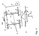
- Fig. 1 shows a basic scheme 10 of a pair of supports according to the invention a positioning device in which a first strut 12 and a second strut 14 are arranged parallel to each other and with predetermined by the construction distance.
- Both struts 12, 14 are adjustable in length, which is shown in the first scheme 10 by a piston-cylinder assembly 16.
- drive conceivable, such as hydraulic, pneumatic or electric, but also a mechanical length adjustment, which in turn is then moved by a pneumatic, hydraulic or electric drive.
- a manual Adjustment conceivable to use for example by means of a crank in the event of a drive failure.
- the struts 12, 14 are at a first end of their longitudinal extent, in the Fig. 1 shown above, with a first 18 and a second universal joint 20 with a support structure 22 firmly connected.
- each universal joint 18, 20 each have a first 24 and a second pivot bearing 26.
- the respective first pivot bearing 24 are fixedly connected to the support structure 22 and have a construction-related fixed distance from each other.
- the first pivot bearings 24 are arranged so that they have a common first pivot axis 28.
- the struts 12, 14 each have a third pivot bearing 30, these third pivot bearings 30 are mounted together on a fourth pivot bearing 32.
- the third pivot bearings 30 have a predetermined distance from each other by the construction and also pivot together on a second pivot axis 34.
- the second pivot axis 34 is spaced by a predetermined amount from the pivot axis 28 whereby the required length of the strut pairs is determined.
- the common pivot bearing 32 with pivot axis 34 is in turn fixedly connected to a usable as a workpiece carrier, moving platform 38.
- the platform 38 receives with respect to a fixed support structure 22 with the arrows in Fig. 1 symbolized mobility.
- the distance of the pivot axis 28 and 34 changes, for example, axis 34 can extend to the position of axis 36.
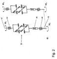
- FIG. 2 shows a first scheme 40 for kinematic coupling of the strut pair, which transmits by means of a hinge assembly, the drive power of a motor on a strut pair in a certain way.
- the drive power of the motor can be independent of the position and orientation of the pivoted by dese hinge assembly Struts are transferred without causing a jamming or jamming.
- one of the two shafts 42 and 43 can be used as drive or driven side. If, for example, shaft 42 is used as the output-side shaft, then it is parallel to the respective strut axis 12 or 14 of FIG Fig. 1 to arrange.
- the drive-side shaft 43 is decoupled from the position and orientation of a strut by the described hinge assembly and can be associated with its pivot bearing 46 either a support structure 22 or the axle of the pivot bearing 24.
- two hinge assemblies 40 are needed to drive a strut pair. This makes it possible to distribute the drive power required for strut adjustment of a drive on both struts. It does not matter at which end of the struts the respective bearings are arranged.
- Fig. 1 could the joint combinations 30, 32 and the individual joints of the universal joints 18, 20 replaced or replaced with each other.
- both joints 30, 32 could also be arranged at the upper end of the struts 12, 14, while the cardan joints 18, 20 could then be arranged at the lower end.
- the hinge assembly 40 may be associated with either the platform-side hinges or the joints of the support structure to transfer the drive power to the strut pair.
- a torsionally rigid length compensation element 48 and a third universal joint 50 is disposed on the first axis of rotation 42.
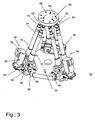
- Fig. 3 shows a first positioning device 52 as a three-dimensional view.
- a base plate 54 is connected to first connecting elements 56 with a first 58, a second 60 and a third strut pair 62.
- the base plate 54 is approximately honeycomb-shaped, wherein a first end of the strut pairs 58, 60, 62, namely the lower end, is disposed on each second side of the base plate 54. In this way, a line-symmetrical starting position for the strut pairs 58, 60, 62 is achieved, which has a particularly favorable effect on the forces to be absorbed by the positioning device 52 and their forwarding.
- Each strut of one of the strut pairs 58, 60, 62 is connected at its upper end by means of a universal joint 64 with a tool plate 66.
- the universal joints 64 are cardan joints and the tool plate 66 designed in the present example as a disc.
- the diameter of the tool plate 66 is selected smaller than the outer diameter of the base plate 54, so that the pairs of struts each have a certain angle to an imaginary vertical on the base plate 54, at least in a starting position in which the pairs of struts have an equal length. However, this starting position can change accordingly according to the length adjustment possibility of the individual struts.
- the tool plate 66 has a number of recesses 68, such as holes, through holes or threaded holes that allow mounting of various tools on this tool plate 66.
- a tool is a pin, a fixing gripper or other connecting element with the workpiece.
- each of the strut pairs 58, 60, 62 has.
- the first strut pair 58 has a first 70 and a second strut 72, which consists essentially of a first 74 and a second cylindrical member 76.
- the second cylindrical component 76 is guided in the first 74 so that a telescopic extension of the components 74, 76 is made possible, wherein preferably the cylindrical components 74, 76 against each other have a rotational degree of freedom along the common axis of symmetry, which is why according to the invention on the struts only Switzerland- and compressive forces, but no moments can be exerted and a distortion of the positioning is avoided.
- the extension of the components via a built-spindle or screw.
- a universal joint 64 to each of the struts 70, 72 ensures that the predetermined distance between the struts at the connection point to the tool plate 66 is not changeable.
- the universal joint 64 has a gimbal bearing, that is, the struts 70, 72 are provided in principle with a storage, the has two degrees of freedom.
- a fifth pivot bearing 78 and correspondingly at the lower end of the second strut 72 a sixth pivot bearing 80 is arranged.
- the distance of the fifth 78 to the sixth pivot bearing 80 relative to the bearing axis centers corresponds to the distance of the upper universal joints 64 to each other.
- the struts 68, 70 are arranged in any case parallel to each other, as long as they have an equal length. This is a problem that relates to a synchronous extension or shortening of the struts 68, 70, which will be explained in more detail later.
- the fifth 78 and the sixth pivot bearing 80 are mounted with their bearing axes so that they are only perpendicular to a further bearing axis 82 of a seventh pivot bearing 84 are pivotable.
- the seventh pivot axis 84 is located tangent to an imaginary circle about a virtual perpendicular to the base plate 54 and in the center thereof.
- the first strut pair 58 has a common electric drive 86 which is connected in the lower region of the struts 70, 72 with a connecting element 88 with a support member 90.
- the support member 90 is connected to the bearing axis 82 so that it pivots with rotation of the axis with and pivoted in this way, both the connecting element 88 and the electric motor 86 in the case of a pivoting movement. In this way, it is ensured that the relative position of the electric motor 68 does not change to the strut feet of the first strut pair 58.
- the details of a possible power transmission or torque transmission from the electric motor 68 to the first strut pair 58 will be explained in more detail later, since in principle there are several possibilities.
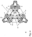
- Fig. 4 shows the first positioning device 52 in a plan view from above on the tool plate 66, wherein the pairs of struts 58, 60, 62 have an equal length, so that the tool plate 66 is located in this view exactly centered above the base plate 54.
- the reference numerals are for the same parts as those in FIG Fig. 3 can be seen, used accordingly.
- FIG. 5 shows an enlarged detail of the foot of the first pair of struts 58, wherein the electric motor 68, the connecting element 88, the sixth pivot bearing 80, the bearing axis 82 and the first connecting element 56 are shown enlarged.
- significantly lower connecting elements 92 are shown, which connects the first cylindrical member 74 of the first strut 70 fixed to a first pivot fork 94 of the fifth pivot bearing 74. With a corresponding pivoting fork 94 and the sixth pivot bearing 80 of the second strut 72 is connected.
- Fig. 6 shows in a cross section through the bearing axis 82, a first embodiment of the mechanical connection 95 in the form of a fourth 98 and a fifth universal joint 100 according to the first scheme in Fig. 2 .
- the universal joints 98, 100 are connected on the one hand with rods 102, which cause a rotational movement of the second cylindrical member 76 under the corresponding component of the second strut 62.
- the universal joints 98, 100 are connected to coupling elements 104, which in turn are connected to drive shafts 106.
- the drive 86 both drive shafts 106 drives at a same speed, so as to ensure that the strut pairs extend or shorten evenly in their longitudinal extent.
- first strut pair 58 this should be done by the common drive by a common gear, but in this figure does not fall into the image plane and thus is not shown.
- this type of Drive is to ensure that one of the second components 76 is stretched by a left-hand rotation while the other is driven by a clockwise rotation and thus extended by a clockwise rotation (or vice versa).
- the drive acts with a correspondingly reversed direction of rotation.
- Fig. 7 shows a second embodiment possibility for driving a length adjustment of pairs of struts, wherein the essential difference between the embodiment of the preceding figure and this is seen in that a second electric motor 108 drives a toothed belt 110, which is also guided over the drive wheels 112, which in essentially fulfill the function of the drive shafts 106 of the previously presented embodiment.
- the tension in the toothed belt is achieved by means of two adjustable tension rollers 107, which apply to a toothless rear side of the toothed belt 110 a predetermined by the setting force, and hold the toothed belt 110 in this way to a predetermined by the design bias.
- a drive of the second cylindrical components 76 is also achieved, which is in the same direction, so that in the construction of the struts is advantageously not to pay attention to a rotation in the drive of the components.
- Fig. 8 shows the upper end of the strut pairs 58, 60, 62 at their junction with the tool plate 66. Also in this figure, known parts and components are provided with the corresponding reference numerals as previously introduced. In the Fig. 8 are the hinge axes 114 drawn so that the degrees of freedom of the joints are as visible as possible. Namely, in the next following figures, it is shown how possible positions with the first positioning device 52, which are provided with such joints 64, appear.
- Fig. 9 shows a first position 116 of the first positioning device 52, in which the workpiece plate 66 is located exactly centered above the base plate 54 and also the strut pairs 58, 60, 62 were retracted to their minimum length.
- Fig. 10 shows a second position 118 of the first positioning device 52, in which the tool plate 66 is also located exactly centered above the base plate 54, the strut pairs 58, 60, 62, however, have their maximum length.
- Fig. 10 With Fig. 9 it can be seen how the tool plate 66 can be positioned along one of its axes of movement.
- Fig. 11 shows a third position 120 of the first positioning device 52, wherein the strut pairs 58, 60, 62 has a mean length compared to that of Fig. 9 and Fig. 10 to have.
- Fig. 12 shows a fourth position 122 of the first positioning device 52, in which the left in the image to be seen pair of struts has a shorter longitudinal extent than the other two pairs of struts, so that in the result, the tool plate 66 is located almost immediately above the left in the image strut pair.
- the convincedptatteization is still parallel to the base plate 54, as arranged in the figures before. The figure makes it clear that, depending on the force and moment effect on the tool plate 66 not only pressure forces on the strut pairs 58, 60, 62 can act, but also tensile forces, depending on how the force or torque acts on the tool plate 66.
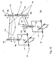
- Fig. 13 relates to a second embodiment 124 of a lower assembly, which transmits the drive power of a motor to a strut pair in a certain way.
- this figure shows only a scheme of the interaction of different components, the symbolism of the components as in Fig. 1 or 2 was chosen. Therefore, only the essential differences in comparison to the preceding drive systems will be described in the following.
- the drive power for a fourth strut pair 126 is provided by a drive shaft 128. How the drive shaft 128 itself is driven, is not shown in detail, but this can be done pneumatically, hydraulically, electrically or in other ways known in the art. Via a gear 130, the drive power of the drive shaft 128 is transmitted to the struts of the fourth strut pair 126.
- the transmission 130 has a first pinion 132 which is connected to a first connecting shaft 134 and rotates in the drive case. The rotation causes the drive of a second pinion 136, which is arranged on a first strut rod 138.
- a third pinion 140 disposed on the drive shaft 128 drives a second drive shaft 142, which in turn drives a fourth pinion 144 drives, which in turn is arranged on a second strut rod 146.
- the strut rods 138, 146 are rotatable about their longitudinal axis and stored accordingly, wherein the pointing in the strut end storage, in the manner already described above with a gimbal 148 is mounted.
- connecting rods 150 are provided which connect the drive with the said bearing.
- connecting rods 150 which connect the corresponding bearing symbols on the drive shaft 128 with the bearing symbols on the strut rods 138, 146.
- connecting rods 150 a housing or the bearing forces receives.
- a torsionally rigid length compensation 127 finally allows the common pivoting of the strut pair about the axes of rotation 26, without affecting the transmission of the drive power.
- a third embodiment 152 of the drive according to the invention uses a belt drive 152, which may for example be designed as a toothed belt or V-belt or as a pull belt to drive two drive wheels 154.
- the drive wheels 154 each act on a first bevel gear 156 of a bevel gear 158, which drives a second bevel gear 160 of the bevel gear 158, which acts on strut rods 162.
- These strut rods 162 are gimbals mounted in a universal bearing 164.
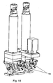
- Fig. 15 shows an embodiment of the third embodiment 152, which in Fig. 14 is shown schematically and shown in this figure as a design proposal in principle. Therefore, the corresponding visible components are also corresponding to the reference numerals FIG. 14 Mistake.
- a fifth plane 174 is still visible, which is parallel to the fourth plane 172 and defined by a bearing 176, namely a pivot bearing, which is closest to a support leg 178.
- a bearing 176 namely a pivot bearing
- the support leg 178 of the connecting element to a base structure, not shown in this figure to which this embodiment could be connected.
- Fig. 16 shows a sectional view of the third embodiment 152, which is why again reference numerals are used as before.
- a rotary motor 178 is arranged so that it drives one of the drive wheels 154 by means of a shaft 180.
- the other drive wheel 154 is in turn driven by the drive belt 153, which drives another shaft 182.
- the corresponding secondary shafts 184 of the length-adjustable struts 186 are driven.
- the distance between the individual adjustable struts 186 is fixed both by the design-related distance of the shaft 180 and the further shaft 182 and by the connection point with a tool plate, not shown, at the other end of the length-adjustable struts 186 in the region of the upper universal joints 190.
- a brake 188 is arranged on the side facing away from the drive wheel 154, which blocks the further shaft 182, if necessary. In this way it can be ensured with simple means that the length-adjustable struts 186 are fixed in a predetermined position, without the drive would have to absorb any forces acting. This gives this arrangement special mechanical stability.
- FIG. 17 Another brake assembly is in the Fig. 17 which again represents a detailed representation of the first strut pair 58, wherein it is merely intended to show that in this figure a second brake 194 is already integrated in the electric motor 86.
- Fig. 18 shows a variant of the brake 196, which has two partial brakes, arranged on a rotary shaft and a further rotary shaft which drives the respective secondary shafts of the two struts respectively.
- a brake redundancy is achieved. Even if one of the partial brakes of the third brake 196 should fail, the other partial brake brakes both secondary shafts via the mechanical active coupling as well as the secondary shaft, which is then not directly braked.
- the brakes are easily accessible, which simplifies the maintenance and control of the brakes.
- Fig. 19 shows another way and position to arrange a pair of brakes 198.
- second partial brakes are in turn integrated in each of the struts, so that the partial brake act directly on the secondary shafts and can thus fix each individual strut by the corresponding braking forces.
- the advantage lies in the fact that the design is even more compact and also the mechanical redundancy of the brake is maintained.
Applications Claiming Priority (2)
| Application Number | Priority Date | Filing Date | Title |
|---|---|---|---|
| DE102006011823A DE102006011823A1 (de) | 2006-03-13 | 2006-03-13 | Positioniereinrichtung |
| PCT/EP2007/001890 WO2007104446A1 (de) | 2006-03-13 | 2007-03-06 | Positioniereinrichtung |
Publications (2)
| Publication Number | Publication Date |
|---|---|
| EP1998930A1 EP1998930A1 (de) | 2008-12-10 |
| EP1998930B1 true EP1998930B1 (de) | 2010-05-12 |
Family
ID=38121894
Family Applications (1)
| Application Number | Title | Priority Date | Filing Date |
|---|---|---|---|
| EP07711799A Not-in-force EP1998930B1 (de) | 2006-03-13 | 2007-03-06 | Positioniereinrichtung |
Country Status (13)
| Country | Link |
|---|---|
| US (1) | US8225692B2 (ja) |
| EP (1) | EP1998930B1 (ja) |
| JP (1) | JP5430947B2 (ja) |
| KR (1) | KR101319366B1 (ja) |
| CN (1) | CN101400476B (ja) |
| AT (1) | ATE467478T1 (ja) |
| BR (1) | BRPI0709591A2 (ja) |
| CA (1) | CA2643976C (ja) |
| DE (2) | DE102006011823A1 (ja) |
| ES (1) | ES2346257T3 (ja) |
| MX (1) | MX2008011703A (ja) |
| RU (1) | RU2441743C2 (ja) |
| WO (1) | WO2007104446A1 (ja) |
Cited By (1)
| Publication number | Priority date | Publication date | Assignee | Title |
|---|---|---|---|---|
| CN102248535A (zh) * | 2011-07-18 | 2011-11-23 | 燕山大学 | 含双复合驱动分支三腿五自由度并联机构 |
Families Citing this family (33)
| Publication number | Priority date | Publication date | Assignee | Title |
|---|---|---|---|---|
| DE102006046758A1 (de) * | 2006-09-29 | 2008-04-03 | Abb Patent Gmbh | Vorrichtung insbesondere zum Positionieren von Objekten |
| US9292016B2 (en) * | 2007-10-26 | 2016-03-22 | Ariel Andre Waitzman | Automated welding of moulds and stamping tools |
| US9545697B2 (en) * | 2009-04-06 | 2017-01-17 | The Boeing Company | Automated hole generation |
| DE102009057585B4 (de) * | 2009-12-09 | 2013-11-28 | Multivac Sepp Haggenmüller Gmbh & Co. Kg | Verfahren zum Kalibrieren eines Roboters |
| MX2012010435A (es) | 2010-03-11 | 2013-01-29 | Sumitomo Metal Ind | Aparato de localizacion, sistema de trabajo, y aparato de trabajo en caliente. |
| SE535182C2 (sv) * | 2010-06-17 | 2012-05-08 | Exechon Ab | En parallellkinematisk maskin med kardanhållare |
| CN102380771B (zh) * | 2011-11-11 | 2013-04-10 | 浙江理工大学 | 高刚度冗余驱动三自由度并联机构 |
| CN102366896B (zh) * | 2011-11-11 | 2013-10-30 | 浙江理工大学 | 具有两条垂直交错转轴的三自由度并联机构 |
| DE102012202170A1 (de) * | 2012-02-14 | 2013-06-13 | Carl Zeiss Smt Gmbh | Positionsmanipulator für ein optisches Bauelement |
| US9359176B2 (en) * | 2012-03-20 | 2016-06-07 | GM Global Technology Operations LLC | Movement device configured for moving a payload |
| US9289900B2 (en) * | 2012-08-24 | 2016-03-22 | Abb Technology Ltd | Calibration tool for a delta robot |
| WO2014053670A1 (es) * | 2012-10-02 | 2014-04-10 | Avs Added Value Industrial Engineering Solutions, S.L. | Manipulador para una cámara de ultra-alto vacío |
| US9694455B2 (en) * | 2012-12-05 | 2017-07-04 | Alio Industries, Inc. | Precision tripod motion system with six degrees of freedom |
| GB2512059B (en) * | 2013-03-18 | 2016-08-31 | Rolls Royce Plc | An independently moveable machine tool |
| JP6250372B2 (ja) * | 2013-11-22 | 2017-12-20 | Ntn株式会社 | 自動溶接機 |
| US11458579B2 (en) * | 2013-12-06 | 2022-10-04 | Huber Diffraktionstechnik Gmbh & Co. Kg | Redundant parallel positioning table device |
| CN104029195B (zh) * | 2014-05-21 | 2016-06-29 | 燕山大学 | 一种两转动一移动过约束并联机构 |
| US20180333842A1 (en) * | 2014-06-09 | 2018-11-22 | onCue Strategies | Autonomous Control of an Extendable Apparatus |
| DE102014118364A1 (de) * | 2014-12-10 | 2016-06-16 | Wittenstein Ag | Dreiachsversteller |
| GB201504846D0 (en) * | 2015-03-23 | 2015-05-06 | Rolls Royce Plc | Machine tools |
| RU2605059C1 (ru) * | 2015-07-27 | 2016-12-20 | Общество с ограниченной ответственностью "Лапик" | Устройство для позиционирования исполнительного органа |
| CN105921449B (zh) * | 2016-06-28 | 2017-11-17 | 金可丹 | 一种三自由度高铁轨道清洗用自稳移动支撑设备 |
| CN106111591B (zh) * | 2016-06-28 | 2018-07-27 | 嵊州亿源投资管理有限公司 | 一种铁轨清洗专用支撑设备 |
| CN106624835B (zh) * | 2017-01-17 | 2018-10-23 | 山东科技大学 | 一种可一次完成自由曲面加工的微型精密机床 |
| RU176443U1 (ru) * | 2017-09-25 | 2018-01-18 | Акционерное общество "Инжиниринговая компания "АЭМ-технологии" (АО "АЭМ-технологии") | Опора универсальная |
| CN108194795A (zh) * | 2018-01-25 | 2018-06-22 | 燕山大学 | 一种可伸缩变自由度的轻重载转台 |
| PL3628439T3 (pl) * | 2018-09-28 | 2022-05-09 | Picum Mt Gmbh | Obrabiarka |
| CN110948522B (zh) * | 2019-11-19 | 2022-06-21 | 南京熊猫电子股份有限公司 | 一种基于拉线旋转传感器的工业机器人空间位姿测量机构及测量方法 |
| WO2021117647A1 (ja) * | 2019-12-13 | 2021-06-17 | ソニーグループ株式会社 | パラレルリンク装置 |
| DE102020106741A1 (de) | 2020-03-12 | 2021-09-16 | Physik Instrumente (PI) GmbH & Co KG | 6-Achs-Positioniersystem mit arretierender Komponente |
| CN111604883A (zh) * | 2020-04-30 | 2020-09-01 | 南京理工大学 | 多自由度高性能混联机器人 |
| CN115816119A (zh) * | 2020-11-09 | 2023-03-21 | 郦鸿志 | 一种防变形夹具 |
| CN113701013B (zh) * | 2021-07-27 | 2023-01-31 | 北京空间飞行器总体设计部 | 一种适用于细长结构的运动学支撑机构 |
Family Cites Families (22)
| Publication number | Priority date | Publication date | Assignee | Title |
|---|---|---|---|---|
| US703251A (en) * | 1902-04-14 | 1902-06-24 | James A Haire | Pipe-puller. |
| US1789975A (en) * | 1927-02-07 | 1931-01-27 | Hell Co | Mechanical hoist |
| US2803146A (en) * | 1952-02-27 | 1957-08-20 | Houdaille Industries Inc | Top operating mechanism |
| US2765024A (en) * | 1954-04-06 | 1956-10-02 | Houdaille Industries Inc | Automotive front seat regulator |
| US5401128A (en) * | 1991-08-26 | 1995-03-28 | Ingersoll Milling Machine Company | Octahedral machine with a hexapodal triangular servostrut section |
| JP3640087B2 (ja) * | 1994-11-29 | 2005-04-20 | 豊田工機株式会社 | 工作機械 |
| US5656905A (en) | 1995-04-03 | 1997-08-12 | Tsai; Lung-Wen | Multi-degree-of-freedom mechanisms for machine tools and the like |
| FR2735409B1 (fr) | 1995-06-13 | 1997-08-22 | Mach Serdi | Dispositif pour positionner la tige pilote d'une broche d'usinage |
| JPH0966480A (ja) * | 1995-08-29 | 1997-03-11 | Toyoda Mach Works Ltd | 工具ハンドおよびそれを用いた工作機械 |
| US5987726A (en) | 1996-03-11 | 1999-11-23 | Fanuc Robotics North America, Inc. | Programmable positioner for the stress-free assembly of components |
| JPH09271154A (ja) * | 1996-03-29 | 1997-10-14 | Sintokogio Ltd | 電動シリンダ |
| US5787758A (en) | 1996-09-03 | 1998-08-04 | Sheldon/Van Someren, Inc. | Three-axis machine for rapid and rigid manipulation of components |
| US5865063A (en) * | 1996-09-03 | 1999-02-02 | Sheldon/Van Someren, Inc. | Three-axis machine structure that prevents rotational movement |
| US6041500A (en) * | 1998-01-23 | 2000-03-28 | Giddings & Lewis, Inc. | Automatic assembly machine and method utilizing six-axis positioning device |
| US6240799B1 (en) * | 1998-05-26 | 2001-06-05 | Hexel Corporation | Triangular gimbal |
| JP2000130536A (ja) * | 1998-10-27 | 2000-05-12 | Fanuc Ltd | パラレルリンク機構 |
| CN1092092C (zh) * | 2000-04-21 | 2002-10-09 | 清华大学 | 两维移动一维转动空间三轴并联机床结构 |
| US6581437B2 (en) * | 2000-05-12 | 2003-06-24 | Alberta Research Council Inc. | Motion platform and method of use |
| US7172385B2 (en) * | 2002-07-09 | 2007-02-06 | Amir Khajepour | Light weight parallel manipulators using active/passive cables |
| CN100462578C (zh) * | 2003-04-10 | 2009-02-18 | 哈尔滨工业大学 | 锥轴虎克铰 |
| US7673384B2 (en) * | 2006-04-27 | 2010-03-09 | Genesis Systems Group, Llc | Nut runner and hexabot robot |
| DE102006046758A1 (de) * | 2006-09-29 | 2008-04-03 | Abb Patent Gmbh | Vorrichtung insbesondere zum Positionieren von Objekten |
-
2006
- 2006-03-13 DE DE102006011823A patent/DE102006011823A1/de not_active Withdrawn
-
2007
- 2007-03-06 MX MX2008011703A patent/MX2008011703A/es active IP Right Grant
- 2007-03-06 ES ES07711799T patent/ES2346257T3/es active Active
- 2007-03-06 DE DE502007003731T patent/DE502007003731D1/de active Active
- 2007-03-06 JP JP2008558678A patent/JP5430947B2/ja not_active Expired - Fee Related
- 2007-03-06 EP EP07711799A patent/EP1998930B1/de not_active Not-in-force
- 2007-03-06 RU RU2008140322/02A patent/RU2441743C2/ru active
- 2007-03-06 CN CN2007800091757A patent/CN101400476B/zh not_active Expired - Fee Related
- 2007-03-06 KR KR1020087022274A patent/KR101319366B1/ko active IP Right Grant
- 2007-03-06 US US12/282,827 patent/US8225692B2/en active Active
- 2007-03-06 AT AT07711799T patent/ATE467478T1/de active
- 2007-03-06 BR BRPI0709591-0A patent/BRPI0709591A2/pt not_active IP Right Cessation
- 2007-03-06 WO PCT/EP2007/001890 patent/WO2007104446A1/de active Application Filing
- 2007-03-06 CA CA2643976A patent/CA2643976C/en active Active
Cited By (1)
| Publication number | Priority date | Publication date | Assignee | Title |
|---|---|---|---|---|
| CN102248535A (zh) * | 2011-07-18 | 2011-11-23 | 燕山大学 | 含双复合驱动分支三腿五自由度并联机构 |
Also Published As
| Publication number | Publication date |
|---|---|
| US8225692B2 (en) | 2012-07-24 |
| JP5430947B2 (ja) | 2014-03-05 |
| KR101319366B1 (ko) | 2013-10-18 |
| JP2009529434A (ja) | 2009-08-20 |
| KR20080109755A (ko) | 2008-12-17 |
| RU2008140322A (ru) | 2010-04-20 |
| DE102006011823A1 (de) | 2007-09-20 |
| CN101400476B (zh) | 2010-12-15 |
| DE502007003731D1 (de) | 2010-06-24 |
| US20090065664A1 (en) | 2009-03-12 |
| EP1998930A1 (de) | 2008-12-10 |
| RU2441743C2 (ru) | 2012-02-10 |
| ES2346257T3 (es) | 2010-10-13 |
| WO2007104446A1 (de) | 2007-09-20 |
| CN101400476A (zh) | 2009-04-01 |
| BRPI0709591A2 (pt) | 2011-07-19 |
| MX2008011703A (es) | 2009-01-09 |
| CA2643976A1 (en) | 2007-09-20 |
| CA2643976C (en) | 2013-12-03 |
| ATE467478T1 (de) | 2010-05-15 |
Similar Documents
| Publication | Publication Date | Title |
|---|---|---|
| EP1998930B1 (de) | Positioniereinrichtung | |
| EP0812652B1 (de) | Vorrichtung zur Bearbeitung und/oder Montage von Werkstücken | |
| EP0041136B1 (de) | Schwenkantrieb für schwenkbar gelagerte Maschinenteile, insbesondere bei Manipulatoren | |
| DE19611130A1 (de) | Vorrichtung zur Erzeugung einer definierten Positionierung und Orientierung mindestens einer Plattform | |
| EP2927661A2 (de) | Aktuator | |
| EP1754649A1 (de) | Einrichtung zur Verstellung des Radsturzes oder der Vorspur | |
| EP2397279A1 (de) | Knickarmroboter mit Armantrieb | |
| DE2930006A1 (de) | Werkstueckbeschickungsvorrichtung mit beweglichkeit fuer fluchtausgleich | |
| EP2776299B1 (de) | Getriebeeinheit | |
| EP0434915A2 (de) | Doppelkegelradwinkelgetriebe | |
| WO1986004009A1 (fr) | Robots industriels pour differentes applications | |
| WO2007019897A1 (de) | Vorrichtung zum schleifen und/oder finishen eines werkstücks | |
| EP2024144B1 (de) | Roboterhand-antriebsvorrichtung | |
| EP0530479B1 (de) | Vorrichtung zum Verbinden eines Landwirtschaftlichen Gerätes mit einem Traktor. | |
| DE102021213069B3 (de) | Antrieb für eine Lenkachse eines Flurförderzeugs, Lenkachse und Flurförderzeug | |
| DE2461773C2 (de) | Stellgerät als einbaufähige Baueinheit mit Spindelmuttertrieb | |
| DE102006034243A1 (de) | Scheinwerferverstellvorrichtung mit Getriebe | |
| DE102021119523A1 (de) | Chirurgisches Instrument und Lenkgetriebe dafür | |
| AT524936A4 (de) | Plattform für mindestens vierrädrige Kraftfahrzeuge mit Elektroantrieb | |
| EP0864250B1 (de) | Antriebsachse | |
| DE102007021059A1 (de) | Flexibles Gelenk | |
| DE102018118615B4 (de) | Relativführungsvorrichtung für eine radträgerseitig angeordnete Lenkanordnung | |
| DE102021213065B4 (de) | Lenkachse für ein lenkbares Fahrzeug und Flurförderzeug | |
| DE102018107142A1 (de) | Manipulatoreinrichtung | |
| EP3412484A1 (de) | Aggregatlagerung für ein kraftfahrzeug |
Legal Events
| Date | Code | Title | Description |
|---|---|---|---|
| PUAI | Public reference made under article 153(3) epc to a published international application that has entered the european phase |
Free format text: ORIGINAL CODE: 0009012 |
|
| 17P | Request for examination filed |
Effective date: 20080820 |
|
| AK | Designated contracting states |
Kind code of ref document: A1 Designated state(s): AT BE BG CH CY CZ DE DK EE ES FI FR GB GR HU IE IS IT LI LT LU LV MC MT NL PL PT RO SE SI SK TR |
|
| 17Q | First examination report despatched |
Effective date: 20090330 |
|
| GRAP | Despatch of communication of intention to grant a patent |
Free format text: ORIGINAL CODE: EPIDOSNIGR1 |
|
| GRAS | Grant fee paid |
Free format text: ORIGINAL CODE: EPIDOSNIGR3 |
|
| GRAA | (expected) grant |
Free format text: ORIGINAL CODE: 0009210 |
|
| AK | Designated contracting states |
Kind code of ref document: B1 Designated state(s): AT BE BG CH CY CZ DE DK EE ES FI FR GB GR HU IE IS IT LI LT LU LV MC MT NL PL PT RO SE SI SK TR |
|
| REG | Reference to a national code |
Ref country code: GB Ref legal event code: FG4D Free format text: NOT ENGLISH |
|
| REG | Reference to a national code |
Ref country code: CH Ref legal event code: EP |
|
| REG | Reference to a national code |
Ref country code: IE Ref legal event code: FG4D Free format text: LANGUAGE OF EP DOCUMENT: GERMAN |
|
| REF | Corresponds to: |
Ref document number: 502007003731 Country of ref document: DE Date of ref document: 20100624 Kind code of ref document: P |
|
| REG | Reference to a national code |
Ref country code: NL Ref legal event code: VDEP Effective date: 20100512 |
|
| REG | Reference to a national code |
Ref country code: ES Ref legal event code: FG2A Ref document number: 2346257 Country of ref document: ES Kind code of ref document: T3 |
|
| LTIE | Lt: invalidation of european patent or patent extension |
Effective date: 20100512 |
|
| PG25 | Lapsed in a contracting state [announced via postgrant information from national office to epo] |
Ref country code: SE Free format text: LAPSE BECAUSE OF FAILURE TO SUBMIT A TRANSLATION OF THE DESCRIPTION OR TO PAY THE FEE WITHIN THE PRESCRIBED TIME-LIMIT Effective date: 20100512 Ref country code: NL Free format text: LAPSE BECAUSE OF FAILURE TO SUBMIT A TRANSLATION OF THE DESCRIPTION OR TO PAY THE FEE WITHIN THE PRESCRIBED TIME-LIMIT Effective date: 20100512 Ref country code: LT Free format text: LAPSE BECAUSE OF FAILURE TO SUBMIT A TRANSLATION OF THE DESCRIPTION OR TO PAY THE FEE WITHIN THE PRESCRIBED TIME-LIMIT Effective date: 20100512 |
|
| PG25 | Lapsed in a contracting state [announced via postgrant information from national office to epo] |
Ref country code: FI Free format text: LAPSE BECAUSE OF FAILURE TO SUBMIT A TRANSLATION OF THE DESCRIPTION OR TO PAY THE FEE WITHIN THE PRESCRIBED TIME-LIMIT Effective date: 20100512 Ref country code: IS Free format text: LAPSE BECAUSE OF FAILURE TO SUBMIT A TRANSLATION OF THE DESCRIPTION OR TO PAY THE FEE WITHIN THE PRESCRIBED TIME-LIMIT Effective date: 20100912 Ref country code: LV Free format text: LAPSE BECAUSE OF FAILURE TO SUBMIT A TRANSLATION OF THE DESCRIPTION OR TO PAY THE FEE WITHIN THE PRESCRIBED TIME-LIMIT Effective date: 20100512 Ref country code: SI Free format text: LAPSE BECAUSE OF FAILURE TO SUBMIT A TRANSLATION OF THE DESCRIPTION OR TO PAY THE FEE WITHIN THE PRESCRIBED TIME-LIMIT Effective date: 20100512 |
|
| REG | Reference to a national code |
Ref country code: IE Ref legal event code: FD4D |
|
| PG25 | Lapsed in a contracting state [announced via postgrant information from national office to epo] |
Ref country code: PL Free format text: LAPSE BECAUSE OF FAILURE TO SUBMIT A TRANSLATION OF THE DESCRIPTION OR TO PAY THE FEE WITHIN THE PRESCRIBED TIME-LIMIT Effective date: 20100512 Ref country code: CY Free format text: LAPSE BECAUSE OF FAILURE TO SUBMIT A TRANSLATION OF THE DESCRIPTION OR TO PAY THE FEE WITHIN THE PRESCRIBED TIME-LIMIT Effective date: 20100602 |
|
| PG25 | Lapsed in a contracting state [announced via postgrant information from national office to epo] |
Ref country code: IE Free format text: LAPSE BECAUSE OF FAILURE TO SUBMIT A TRANSLATION OF THE DESCRIPTION OR TO PAY THE FEE WITHIN THE PRESCRIBED TIME-LIMIT Effective date: 20100512 Ref country code: PT Free format text: LAPSE BECAUSE OF FAILURE TO SUBMIT A TRANSLATION OF THE DESCRIPTION OR TO PAY THE FEE WITHIN THE PRESCRIBED TIME-LIMIT Effective date: 20100913 Ref country code: DK Free format text: LAPSE BECAUSE OF FAILURE TO SUBMIT A TRANSLATION OF THE DESCRIPTION OR TO PAY THE FEE WITHIN THE PRESCRIBED TIME-LIMIT Effective date: 20100512 Ref country code: EE Free format text: LAPSE BECAUSE OF FAILURE TO SUBMIT A TRANSLATION OF THE DESCRIPTION OR TO PAY THE FEE WITHIN THE PRESCRIBED TIME-LIMIT Effective date: 20100512 |
|
| PG25 | Lapsed in a contracting state [announced via postgrant information from national office to epo] |
Ref country code: CZ Free format text: LAPSE BECAUSE OF FAILURE TO SUBMIT A TRANSLATION OF THE DESCRIPTION OR TO PAY THE FEE WITHIN THE PRESCRIBED TIME-LIMIT Effective date: 20100512 Ref country code: SK Free format text: LAPSE BECAUSE OF FAILURE TO SUBMIT A TRANSLATION OF THE DESCRIPTION OR TO PAY THE FEE WITHIN THE PRESCRIBED TIME-LIMIT Effective date: 20100512 Ref country code: RO Free format text: LAPSE BECAUSE OF FAILURE TO SUBMIT A TRANSLATION OF THE DESCRIPTION OR TO PAY THE FEE WITHIN THE PRESCRIBED TIME-LIMIT Effective date: 20100512 |
|
| PLBE | No opposition filed within time limit |
Free format text: ORIGINAL CODE: 0009261 |
|
| STAA | Information on the status of an ep patent application or granted ep patent |
Free format text: STATUS: NO OPPOSITION FILED WITHIN TIME LIMIT |
|
| 26N | No opposition filed |
Effective date: 20110215 |
|
| PG25 | Lapsed in a contracting state [announced via postgrant information from national office to epo] |
Ref country code: GR Free format text: LAPSE BECAUSE OF FAILURE TO SUBMIT A TRANSLATION OF THE DESCRIPTION OR TO PAY THE FEE WITHIN THE PRESCRIBED TIME-LIMIT Effective date: 20100813 |
|
| REG | Reference to a national code |
Ref country code: DE Ref legal event code: R097 Ref document number: 502007003731 Country of ref document: DE Effective date: 20110214 |
|
| BERE | Be: lapsed |
Owner name: ABB A.G. Effective date: 20110331 |
|
| PG25 | Lapsed in a contracting state [announced via postgrant information from national office to epo] |
Ref country code: MC Free format text: LAPSE BECAUSE OF NON-PAYMENT OF DUE FEES Effective date: 20110331 |
|
| REG | Reference to a national code |
Ref country code: CH Ref legal event code: PL |
|
| GBPC | Gb: european patent ceased through non-payment of renewal fee |
Effective date: 20110306 |
|
| PG25 | Lapsed in a contracting state [announced via postgrant information from national office to epo] |
Ref country code: MT Free format text: LAPSE BECAUSE OF FAILURE TO SUBMIT A TRANSLATION OF THE DESCRIPTION OR TO PAY THE FEE WITHIN THE PRESCRIBED TIME-LIMIT Effective date: 20100512 Ref country code: BE Free format text: LAPSE BECAUSE OF NON-PAYMENT OF DUE FEES Effective date: 20110331 |
|
| PG25 | Lapsed in a contracting state [announced via postgrant information from national office to epo] |
Ref country code: LI Free format text: LAPSE BECAUSE OF NON-PAYMENT OF DUE FEES Effective date: 20110331 Ref country code: CH Free format text: LAPSE BECAUSE OF NON-PAYMENT OF DUE FEES Effective date: 20110331 |
|
| PG25 | Lapsed in a contracting state [announced via postgrant information from national office to epo] |
Ref country code: GB Free format text: LAPSE BECAUSE OF NON-PAYMENT OF DUE FEES Effective date: 20110306 |
|
| REG | Reference to a national code |
Ref country code: AT Ref legal event code: MM01 Ref document number: 467478 Country of ref document: AT Kind code of ref document: T Effective date: 20120306 |
|
| PG25 | Lapsed in a contracting state [announced via postgrant information from national office to epo] |
Ref country code: LU Free format text: LAPSE BECAUSE OF NON-PAYMENT OF DUE FEES Effective date: 20110306 |
|
| PG25 | Lapsed in a contracting state [announced via postgrant information from national office to epo] |
Ref country code: AT Free format text: LAPSE BECAUSE OF NON-PAYMENT OF DUE FEES Effective date: 20120306 |
|
| PG25 | Lapsed in a contracting state [announced via postgrant information from national office to epo] |
Ref country code: TR Free format text: LAPSE BECAUSE OF FAILURE TO SUBMIT A TRANSLATION OF THE DESCRIPTION OR TO PAY THE FEE WITHIN THE PRESCRIBED TIME-LIMIT Effective date: 20100512 Ref country code: BG Free format text: LAPSE BECAUSE OF FAILURE TO SUBMIT A TRANSLATION OF THE DESCRIPTION OR TO PAY THE FEE WITHIN THE PRESCRIBED TIME-LIMIT Effective date: 20100812 |
|
| PG25 | Lapsed in a contracting state [announced via postgrant information from national office to epo] |
Ref country code: HU Free format text: LAPSE BECAUSE OF FAILURE TO SUBMIT A TRANSLATION OF THE DESCRIPTION OR TO PAY THE FEE WITHIN THE PRESCRIBED TIME-LIMIT Effective date: 20100512 |
|
| REG | Reference to a national code |
Ref country code: FR Ref legal event code: PLFP Year of fee payment: 10 |
|
| REG | Reference to a national code |
Ref country code: FR Ref legal event code: PLFP Year of fee payment: 11 |
|
| REG | Reference to a national code |
Ref country code: FR Ref legal event code: PLFP Year of fee payment: 12 |
|
| PGFP | Annual fee paid to national office [announced via postgrant information from national office to epo] |
Ref country code: DE Payment date: 20220322 Year of fee payment: 16 |
|
| PGFP | Annual fee paid to national office [announced via postgrant information from national office to epo] |
Ref country code: IT Payment date: 20220322 Year of fee payment: 16 Ref country code: FR Payment date: 20220322 Year of fee payment: 16 |
|
| PGFP | Annual fee paid to national office [announced via postgrant information from national office to epo] |
Ref country code: ES Payment date: 20220527 Year of fee payment: 16 |
|
| REG | Reference to a national code |
Ref country code: DE Ref legal event code: R119 Ref document number: 502007003731 Country of ref document: DE |
|
| PG25 | Lapsed in a contracting state [announced via postgrant information from national office to epo] |
Ref country code: FR Free format text: LAPSE BECAUSE OF NON-PAYMENT OF DUE FEES Effective date: 20230331 Ref country code: DE Free format text: LAPSE BECAUSE OF NON-PAYMENT OF DUE FEES Effective date: 20231003 |
|
| PG25 | Lapsed in a contracting state [announced via postgrant information from national office to epo] |
Ref country code: ES Free format text: LAPSE BECAUSE OF NON-PAYMENT OF DUE FEES Effective date: 20230307 |
|
| REG | Reference to a national code |
Ref country code: ES Ref legal event code: FD2A Effective date: 20240426 |
|
| PG25 | Lapsed in a contracting state [announced via postgrant information from national office to epo] |
Ref country code: IT Free format text: LAPSE BECAUSE OF NON-PAYMENT OF DUE FEES Effective date: 20230306 Ref country code: ES Free format text: LAPSE BECAUSE OF NON-PAYMENT OF DUE FEES Effective date: 20230307 |