EP1998930B1 - Positioniereinrichtung - Google Patents
Positioniereinrichtung Download PDFInfo
- Publication number
- EP1998930B1 EP1998930B1 EP07711799A EP07711799A EP1998930B1 EP 1998930 B1 EP1998930 B1 EP 1998930B1 EP 07711799 A EP07711799 A EP 07711799A EP 07711799 A EP07711799 A EP 07711799A EP 1998930 B1 EP1998930 B1 EP 1998930B1
- Authority
- EP
- European Patent Office
- Prior art keywords
- struts
- positioning device
- strut
- drive
- pair
- Prior art date
- Legal status (The legal status is an assumption and is not a legal conclusion. Google has not performed a legal analysis and makes no representation as to the accuracy of the status listed.)
- Not-in-force
Links
Images


Classifications
-
- B—PERFORMING OPERATIONS; TRANSPORTING
- B23—MACHINE TOOLS; METAL-WORKING NOT OTHERWISE PROVIDED FOR
- B23Q—DETAILS, COMPONENTS, OR ACCESSORIES FOR MACHINE TOOLS, e.g. ARRANGEMENTS FOR COPYING OR CONTROLLING; MACHINE TOOLS IN GENERAL CHARACTERISED BY THE CONSTRUCTION OF PARTICULAR DETAILS OR COMPONENTS; COMBINATIONS OR ASSOCIATIONS OF METAL-WORKING MACHINES, NOT DIRECTED TO A PARTICULAR RESULT
- B23Q1/00—Members which are comprised in the general build-up of a form of machine, particularly relatively large fixed members
- B23Q1/25—Movable or adjustable work or tool supports
- B23Q1/44—Movable or adjustable work or tool supports using particular mechanisms
- B23Q1/50—Movable or adjustable work or tool supports using particular mechanisms with rotating pairs only, the rotating pairs being the first two elements of the mechanism
- B23Q1/54—Movable or adjustable work or tool supports using particular mechanisms with rotating pairs only, the rotating pairs being the first two elements of the mechanism two rotating pairs only
- B23Q1/545—Movable or adjustable work or tool supports using particular mechanisms with rotating pairs only, the rotating pairs being the first two elements of the mechanism two rotating pairs only comprising spherical surfaces
- B23Q1/5462—Movable or adjustable work or tool supports using particular mechanisms with rotating pairs only, the rotating pairs being the first two elements of the mechanism two rotating pairs only comprising spherical surfaces with one supplementary sliding pair
-
- B—PERFORMING OPERATIONS; TRANSPORTING
- B25—HAND TOOLS; PORTABLE POWER-DRIVEN TOOLS; MANIPULATORS
- B25J—MANIPULATORS; CHAMBERS PROVIDED WITH MANIPULATION DEVICES
- B25J17/00—Joints
- B25J17/02—Wrist joints
-
- B—PERFORMING OPERATIONS; TRANSPORTING
- B25—HAND TOOLS; PORTABLE POWER-DRIVEN TOOLS; MANIPULATORS
- B25J—MANIPULATORS; CHAMBERS PROVIDED WITH MANIPULATION DEVICES
- B25J17/00—Joints
- B25J17/02—Wrist joints
- B25J17/0208—Compliance devices
- B25J17/0216—Compliance devices comprising a stewart mechanism
-
- Y—GENERAL TAGGING OF NEW TECHNOLOGICAL DEVELOPMENTS; GENERAL TAGGING OF CROSS-SECTIONAL TECHNOLOGIES SPANNING OVER SEVERAL SECTIONS OF THE IPC; TECHNICAL SUBJECTS COVERED BY FORMER USPC CROSS-REFERENCE ART COLLECTIONS [XRACs] AND DIGESTS
- Y10—TECHNICAL SUBJECTS COVERED BY FORMER USPC
- Y10T—TECHNICAL SUBJECTS COVERED BY FORMER US CLASSIFICATION
- Y10T74/00—Machine element or mechanism
- Y10T74/20—Control lever and linkage systems
- Y10T74/20207—Multiple controlling elements for single controlled element
- Y10T74/20305—Robotic arm
- Y10T74/20317—Robotic arm including electric motor
-
- Y—GENERAL TAGGING OF NEW TECHNOLOGICAL DEVELOPMENTS; GENERAL TAGGING OF CROSS-SECTIONAL TECHNOLOGIES SPANNING OVER SEVERAL SECTIONS OF THE IPC; TECHNICAL SUBJECTS COVERED BY FORMER USPC CROSS-REFERENCE ART COLLECTIONS [XRACs] AND DIGESTS
- Y10—TECHNICAL SUBJECTS COVERED BY FORMER USPC
- Y10T—TECHNICAL SUBJECTS COVERED BY FORMER US CLASSIFICATION
- Y10T74/00—Machine element or mechanism
- Y10T74/20—Control lever and linkage systems
- Y10T74/20207—Multiple controlling elements for single controlled element
- Y10T74/20305—Robotic arm
- Y10T74/20329—Joint between elements
Definitions
- the invention relates to a positioning with a support structure, with a workpiece carrier and with length-adjustable struts, which are each connected on the one hand to the support structure and the other with the workpiece carrier, wherein the struts are movably mounted at the connection points with the support structure and the workpiece carrier, wherein at least one Part of the struts is adjustable in length and wherein at least a portion of the struts has a drive for length adjustment.
- positioning devices of the generic type have become known from the prior art, for example in the document US-A-6,041,500 that are used in various fields of technology.
- the known positioning devices serve to hold an object in position.
- Such positioning devices are therefore used, for example, to position a workpiece relative to a tool so that the workpiece can be machined with the aid of the tool.
- a body part of a vehicle is positioned in a workstation or the like by means of usually several positioning devices. The thus positioned body can then be processed by, for example, welding robots.
- US 5,787,758 a triaxial positioning device which serves to position objects such as workpieces, tools, sensors, optical surfaces and so on.
- the known positioning device has a support structure, the actuators is connected to an adjustable machine component.
- the machine component receives the object and can be moved and positioned by driving the actuators relative to the support structure.
- the machine component should only be able to be moved in the direction of the axes of a Cartesian coordinate system of the machine component whose origin firmly connected to the machine component. A tilting, pivoting or turning of the machine component about these axes should be prevented.
- the known positioning on three struts, which are hinged on the one hand to the support structure and on the other hand on the machine component.
- the struts are connected to the said parts and formed so that they prevent pivoting of the machine component about these axes.
- the struts have two strut sections, which are hinged together, so that the length of the strut can be adjusted or changed by opening and closing.
- Such positioning devices have the particular disadvantage that they have a large space and space requirements. This leads in particular to the arrangement of the positioning device in a production line or the like to problems because here little space between the robots, conveyor belts, components and so on is available on a regular basis. Furthermore, the known positioning devices do not have the necessary rigidity to meet the sometimes very high loads can. In addition, the assembly of the known positioning designed as consuming.
- the object of the invention is to provide a positioning device which is compact and space-saving and has a high rigidity.
- each strut receives individual forces
- each pair of struts considered as a couple of forces
- the average load of the struts is reduced.
- Another advantage of such an arrangement of struts is the fact that the positioning is designed to be relatively compact in terms of the forces and moments that they can endure.
- the strut number is exactly six.
- the position device has exactly three variable-length strut pairs, which pass on the supporting structure in a particularly favorable manner, the forces and moments of a workpiece in the support structure with a corresponding spatial arrangement.
- each strut pair has a common drive.
- the positioning device is more compact overall and the control effort to control the drives is correspondingly lower.
- the drive is connected with an angle-faithful connection with the respective strut pair, in particular a belt, a toothed belt, a gear or gears.
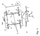
- Fig. 1 shows a basic scheme 10 of a pair of supports according to the invention a positioning device in which a first strut 12 and a second strut 14 are arranged parallel to each other and with predetermined by the construction distance.
- Both struts 12, 14 are adjustable in length, which is shown in the first scheme 10 by a piston-cylinder assembly 16.
- drive conceivable, such as hydraulic, pneumatic or electric, but also a mechanical length adjustment, which in turn is then moved by a pneumatic, hydraulic or electric drive.
- a manual Adjustment conceivable to use for example by means of a crank in the event of a drive failure.
- the struts 12, 14 are at a first end of their longitudinal extent, in the Fig. 1 shown above, with a first 18 and a second universal joint 20 with a support structure 22 firmly connected.
- each universal joint 18, 20 each have a first 24 and a second pivot bearing 26.
- the respective first pivot bearing 24 are fixedly connected to the support structure 22 and have a construction-related fixed distance from each other.
- the first pivot bearings 24 are arranged so that they have a common first pivot axis 28.
- the struts 12, 14 each have a third pivot bearing 30, these third pivot bearings 30 are mounted together on a fourth pivot bearing 32.
- the third pivot bearings 30 have a predetermined distance from each other by the construction and also pivot together on a second pivot axis 34.
- the second pivot axis 34 is spaced by a predetermined amount from the pivot axis 28 whereby the required length of the strut pairs is determined.
- the common pivot bearing 32 with pivot axis 34 is in turn fixedly connected to a usable as a workpiece carrier, moving platform 38.
- the platform 38 receives with respect to a fixed support structure 22 with the arrows in Fig. 1 symbolized mobility.
- the distance of the pivot axis 28 and 34 changes, for example, axis 34 can extend to the position of axis 36.
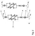
- FIG. 2 shows a first scheme 40 for kinematic coupling of the strut pair, which transmits by means of a hinge assembly, the drive power of a motor on a strut pair in a certain way.
- the drive power of the motor can be independent of the position and orientation of the pivoted by dese hinge assembly Struts are transferred without causing a jamming or jamming.
- one of the two shafts 42 and 43 can be used as drive or driven side. If, for example, shaft 42 is used as the output-side shaft, then it is parallel to the respective strut axis 12 or 14 of FIG Fig. 1 to arrange.
- the drive-side shaft 43 is decoupled from the position and orientation of a strut by the described hinge assembly and can be associated with its pivot bearing 46 either a support structure 22 or the axle of the pivot bearing 24.
- two hinge assemblies 40 are needed to drive a strut pair. This makes it possible to distribute the drive power required for strut adjustment of a drive on both struts. It does not matter at which end of the struts the respective bearings are arranged.
- Fig. 1 could the joint combinations 30, 32 and the individual joints of the universal joints 18, 20 replaced or replaced with each other.
- both joints 30, 32 could also be arranged at the upper end of the struts 12, 14, while the cardan joints 18, 20 could then be arranged at the lower end.
- the hinge assembly 40 may be associated with either the platform-side hinges or the joints of the support structure to transfer the drive power to the strut pair.
- a torsionally rigid length compensation element 48 and a third universal joint 50 is disposed on the first axis of rotation 42.
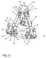
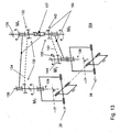
- Fig. 3 shows a first positioning device 52 as a three-dimensional view.
- a base plate 54 is connected to first connecting elements 56 with a first 58, a second 60 and a third strut pair 62.
- the base plate 54 is approximately honeycomb-shaped, wherein a first end of the strut pairs 58, 60, 62, namely the lower end, is disposed on each second side of the base plate 54. In this way, a line-symmetrical starting position for the strut pairs 58, 60, 62 is achieved, which has a particularly favorable effect on the forces to be absorbed by the positioning device 52 and their forwarding.
- Each strut of one of the strut pairs 58, 60, 62 is connected at its upper end by means of a universal joint 64 with a tool plate 66.
- the universal joints 64 are cardan joints and the tool plate 66 designed in the present example as a disc.
- the diameter of the tool plate 66 is selected smaller than the outer diameter of the base plate 54, so that the pairs of struts each have a certain angle to an imaginary vertical on the base plate 54, at least in a starting position in which the pairs of struts have an equal length. However, this starting position can change accordingly according to the length adjustment possibility of the individual struts.
- the tool plate 66 has a number of recesses 68, such as holes, through holes or threaded holes that allow mounting of various tools on this tool plate 66.
- a tool is a pin, a fixing gripper or other connecting element with the workpiece.
- each of the strut pairs 58, 60, 62 has.
- the first strut pair 58 has a first 70 and a second strut 72, which consists essentially of a first 74 and a second cylindrical member 76.
- the second cylindrical component 76 is guided in the first 74 so that a telescopic extension of the components 74, 76 is made possible, wherein preferably the cylindrical components 74, 76 against each other have a rotational degree of freedom along the common axis of symmetry, which is why according to the invention on the struts only Switzerland- and compressive forces, but no moments can be exerted and a distortion of the positioning is avoided.
- the extension of the components via a built-spindle or screw.
- a universal joint 64 to each of the struts 70, 72 ensures that the predetermined distance between the struts at the connection point to the tool plate 66 is not changeable.
- the universal joint 64 has a gimbal bearing, that is, the struts 70, 72 are provided in principle with a storage, the has two degrees of freedom.
- a fifth pivot bearing 78 and correspondingly at the lower end of the second strut 72 a sixth pivot bearing 80 is arranged.
- the distance of the fifth 78 to the sixth pivot bearing 80 relative to the bearing axis centers corresponds to the distance of the upper universal joints 64 to each other.
- the struts 68, 70 are arranged in any case parallel to each other, as long as they have an equal length. This is a problem that relates to a synchronous extension or shortening of the struts 68, 70, which will be explained in more detail later.
- the fifth 78 and the sixth pivot bearing 80 are mounted with their bearing axes so that they are only perpendicular to a further bearing axis 82 of a seventh pivot bearing 84 are pivotable.
- the seventh pivot axis 84 is located tangent to an imaginary circle about a virtual perpendicular to the base plate 54 and in the center thereof.
- the first strut pair 58 has a common electric drive 86 which is connected in the lower region of the struts 70, 72 with a connecting element 88 with a support member 90.
- the support member 90 is connected to the bearing axis 82 so that it pivots with rotation of the axis with and pivoted in this way, both the connecting element 88 and the electric motor 86 in the case of a pivoting movement. In this way, it is ensured that the relative position of the electric motor 68 does not change to the strut feet of the first strut pair 58.
- the details of a possible power transmission or torque transmission from the electric motor 68 to the first strut pair 58 will be explained in more detail later, since in principle there are several possibilities.
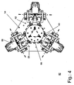
- Fig. 4 shows the first positioning device 52 in a plan view from above on the tool plate 66, wherein the pairs of struts 58, 60, 62 have an equal length, so that the tool plate 66 is located in this view exactly centered above the base plate 54.
- the reference numerals are for the same parts as those in FIG Fig. 3 can be seen, used accordingly.
- FIG. 5 shows an enlarged detail of the foot of the first pair of struts 58, wherein the electric motor 68, the connecting element 88, the sixth pivot bearing 80, the bearing axis 82 and the first connecting element 56 are shown enlarged.
- significantly lower connecting elements 92 are shown, which connects the first cylindrical member 74 of the first strut 70 fixed to a first pivot fork 94 of the fifth pivot bearing 74. With a corresponding pivoting fork 94 and the sixth pivot bearing 80 of the second strut 72 is connected.
- Fig. 6 shows in a cross section through the bearing axis 82, a first embodiment of the mechanical connection 95 in the form of a fourth 98 and a fifth universal joint 100 according to the first scheme in Fig. 2 .
- the universal joints 98, 100 are connected on the one hand with rods 102, which cause a rotational movement of the second cylindrical member 76 under the corresponding component of the second strut 62.
- the universal joints 98, 100 are connected to coupling elements 104, which in turn are connected to drive shafts 106.
- the drive 86 both drive shafts 106 drives at a same speed, so as to ensure that the strut pairs extend or shorten evenly in their longitudinal extent.
- first strut pair 58 this should be done by the common drive by a common gear, but in this figure does not fall into the image plane and thus is not shown.
- this type of Drive is to ensure that one of the second components 76 is stretched by a left-hand rotation while the other is driven by a clockwise rotation and thus extended by a clockwise rotation (or vice versa).
- the drive acts with a correspondingly reversed direction of rotation.
- Fig. 7 shows a second embodiment possibility for driving a length adjustment of pairs of struts, wherein the essential difference between the embodiment of the preceding figure and this is seen in that a second electric motor 108 drives a toothed belt 110, which is also guided over the drive wheels 112, which in essentially fulfill the function of the drive shafts 106 of the previously presented embodiment.
- the tension in the toothed belt is achieved by means of two adjustable tension rollers 107, which apply to a toothless rear side of the toothed belt 110 a predetermined by the setting force, and hold the toothed belt 110 in this way to a predetermined by the design bias.
- a drive of the second cylindrical components 76 is also achieved, which is in the same direction, so that in the construction of the struts is advantageously not to pay attention to a rotation in the drive of the components.
- Fig. 8 shows the upper end of the strut pairs 58, 60, 62 at their junction with the tool plate 66. Also in this figure, known parts and components are provided with the corresponding reference numerals as previously introduced. In the Fig. 8 are the hinge axes 114 drawn so that the degrees of freedom of the joints are as visible as possible. Namely, in the next following figures, it is shown how possible positions with the first positioning device 52, which are provided with such joints 64, appear.
- Fig. 9 shows a first position 116 of the first positioning device 52, in which the workpiece plate 66 is located exactly centered above the base plate 54 and also the strut pairs 58, 60, 62 were retracted to their minimum length.
- Fig. 10 shows a second position 118 of the first positioning device 52, in which the tool plate 66 is also located exactly centered above the base plate 54, the strut pairs 58, 60, 62, however, have their maximum length.
- Fig. 10 With Fig. 9 it can be seen how the tool plate 66 can be positioned along one of its axes of movement.
- Fig. 11 shows a third position 120 of the first positioning device 52, wherein the strut pairs 58, 60, 62 has a mean length compared to that of Fig. 9 and Fig. 10 to have.
- Fig. 12 shows a fourth position 122 of the first positioning device 52, in which the left in the image to be seen pair of struts has a shorter longitudinal extent than the other two pairs of struts, so that in the result, the tool plate 66 is located almost immediately above the left in the image strut pair.
- the convincedptatteization is still parallel to the base plate 54, as arranged in the figures before. The figure makes it clear that, depending on the force and moment effect on the tool plate 66 not only pressure forces on the strut pairs 58, 60, 62 can act, but also tensile forces, depending on how the force or torque acts on the tool plate 66.
- Fig. 13 relates to a second embodiment 124 of a lower assembly, which transmits the drive power of a motor to a strut pair in a certain way.
- this figure shows only a scheme of the interaction of different components, the symbolism of the components as in Fig. 1 or 2 was chosen. Therefore, only the essential differences in comparison to the preceding drive systems will be described in the following.
- the drive power for a fourth strut pair 126 is provided by a drive shaft 128. How the drive shaft 128 itself is driven, is not shown in detail, but this can be done pneumatically, hydraulically, electrically or in other ways known in the art. Via a gear 130, the drive power of the drive shaft 128 is transmitted to the struts of the fourth strut pair 126.
- the transmission 130 has a first pinion 132 which is connected to a first connecting shaft 134 and rotates in the drive case. The rotation causes the drive of a second pinion 136, which is arranged on a first strut rod 138.
- a third pinion 140 disposed on the drive shaft 128 drives a second drive shaft 142, which in turn drives a fourth pinion 144 drives, which in turn is arranged on a second strut rod 146.
- the strut rods 138, 146 are rotatable about their longitudinal axis and stored accordingly, wherein the pointing in the strut end storage, in the manner already described above with a gimbal 148 is mounted.
- connecting rods 150 are provided which connect the drive with the said bearing.
- connecting rods 150 which connect the corresponding bearing symbols on the drive shaft 128 with the bearing symbols on the strut rods 138, 146.
- connecting rods 150 a housing or the bearing forces receives.
- a torsionally rigid length compensation 127 finally allows the common pivoting of the strut pair about the axes of rotation 26, without affecting the transmission of the drive power.
- a third embodiment 152 of the drive according to the invention uses a belt drive 152, which may for example be designed as a toothed belt or V-belt or as a pull belt to drive two drive wheels 154.
- the drive wheels 154 each act on a first bevel gear 156 of a bevel gear 158, which drives a second bevel gear 160 of the bevel gear 158, which acts on strut rods 162.
- These strut rods 162 are gimbals mounted in a universal bearing 164.
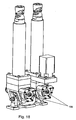
- Fig. 15 shows an embodiment of the third embodiment 152, which in Fig. 14 is shown schematically and shown in this figure as a design proposal in principle. Therefore, the corresponding visible components are also corresponding to the reference numerals FIG. 14 Mistake.
- a fifth plane 174 is still visible, which is parallel to the fourth plane 172 and defined by a bearing 176, namely a pivot bearing, which is closest to a support leg 178.
- a bearing 176 namely a pivot bearing
- the support leg 178 of the connecting element to a base structure, not shown in this figure to which this embodiment could be connected.
- Fig. 16 shows a sectional view of the third embodiment 152, which is why again reference numerals are used as before.
- a rotary motor 178 is arranged so that it drives one of the drive wheels 154 by means of a shaft 180.
- the other drive wheel 154 is in turn driven by the drive belt 153, which drives another shaft 182.
- the corresponding secondary shafts 184 of the length-adjustable struts 186 are driven.
- the distance between the individual adjustable struts 186 is fixed both by the design-related distance of the shaft 180 and the further shaft 182 and by the connection point with a tool plate, not shown, at the other end of the length-adjustable struts 186 in the region of the upper universal joints 190.
- a brake 188 is arranged on the side facing away from the drive wheel 154, which blocks the further shaft 182, if necessary. In this way it can be ensured with simple means that the length-adjustable struts 186 are fixed in a predetermined position, without the drive would have to absorb any forces acting. This gives this arrangement special mechanical stability.
- FIG. 17 Another brake assembly is in the Fig. 17 which again represents a detailed representation of the first strut pair 58, wherein it is merely intended to show that in this figure a second brake 194 is already integrated in the electric motor 86.
- Fig. 18 shows a variant of the brake 196, which has two partial brakes, arranged on a rotary shaft and a further rotary shaft which drives the respective secondary shafts of the two struts respectively.
- a brake redundancy is achieved. Even if one of the partial brakes of the third brake 196 should fail, the other partial brake brakes both secondary shafts via the mechanical active coupling as well as the secondary shaft, which is then not directly braked.
- the brakes are easily accessible, which simplifies the maintenance and control of the brakes.
- Fig. 19 shows another way and position to arrange a pair of brakes 198.
- second partial brakes are in turn integrated in each of the struts, so that the partial brake act directly on the secondary shafts and can thus fix each individual strut by the corresponding braking forces.
- the advantage lies in the fact that the design is even more compact and also the mechanical redundancy of the brake is maintained.
Landscapes
- Engineering & Computer Science (AREA)
- Mechanical Engineering (AREA)
- Robotics (AREA)
- Manipulator (AREA)
- Machine Tool Units (AREA)
- Bending Of Plates, Rods, And Pipes (AREA)
- Jigs For Machine Tools (AREA)
- Automatic Assembly (AREA)
- Details Of Measuring And Other Instruments (AREA)
- Wire Bonding (AREA)
- Eye Examination Apparatus (AREA)
- Die Bonding (AREA)
- Gear Transmission (AREA)
Description
- Die Erfindung betrifft eine Positioniereinrichtung mit einer Stützstruktur, mit einem Werkstückträger und mit längenverstellbaren Streben, die jeweils einerseits mit der Stützstruktur und andererseits mit dem Werkstückträger verbunden sind, wobei die Streben an den Verbindungsstellen mit der Stützstruktur und dem Werkstückträger beweglich gelagert sind, wobei wenigstens ein Teil der Streben längenverstellbar ist und wobei wenigstens ein Teil der Streben einen Antrieb zur Längenverstellung aufweist.
- Aus dem Stand der Technik sind unterschiedliche Positioniereinrichtungen der gattungsgemäßen Art bekannt geworden wie z.B. im Dokument
US-A-6,041,500 , die in verschiedenen Bereichen der Technik zum Einsatz kommen. Die bekannten Positioniereinrichtungen dienen dazu, ein Objekt in Position zu halten. Derartige Positioniereinrichtungen werden daher beispielsweise eingesetzt, um ein Werkstück gegenüber einem Werkzeug so zu positionieren, dass das Werkstück mit Hilfe des Werkzeug bearbeitet werden kann. In der Automobilindustrie wird beispielsweise ein Karosserieteil eines Fahrzeuges mit Hilfe von üblicherweise mehreren Positioniereinrichtungen in einer Arbeitsstation oder ähnlichem positioniert. Die so positionierte Karosserie kann dann von zum Beispiel Schweißrobotern bearbeitet werden. - So beschreibt die
US 5,787,758 eine dreiachsige Positioniereinrichtung, die der Positionierung von Objekten, wie beispielsweise Werkstücke, Werkzeug, Sensoren, optische Oberflächen und so weiter dient. Die bekannte Positioniereinrichtung weist eine Stützstruktur auf, die Stellglieder mit einer verstellbaren Maschinenkomponente verbunden ist. Die Maschinenkomponente nimmt das Objekt auf und kann durch das Ansteuern der Stellglieder relativ zu der Stützstruktur bewegt und positioniert werden. Allerdings soll die Maschinenkomponente lediglich in Richtung der Achsen eines karthesischen Koordinatensystems der Maschinenkomponente bewegt werden können, dessen Ursprung fest mit der Maschinenkomponente verbunden ist. Ein Kippen, Verschwenken oder Drehen der Maschinenkomponente um diese Achsen soll unterbunden sein. Für diesen Zweck weist die bekannte Positioniereinrichtung drei Streben auf, die einerseits an der Stützstruktur und andererseits an der Maschinenkomponente angelenkt sind. Die Streben sind dabei derart mit den genannten Teilen verbunden und ausgebildet, dass diese ein Verschwenken der Maschinenkomponente um diese Achsen verhindern. Die Streben weisen zwei Strebenabschnitte auf, die klappbar miteinander verbunden sind, so dass die Länge der Strebe durch auf- und zuklappen verstellt beziehungsweise verändert werden kann. - Solche Positioniereinrichtungen haben insbesondere den Nachteil, dass diese einen großen Platz- und Raumbedarf haben. Dies führt insbesondere bei der Anordnung der Positioniereinrichtung in einer Fertigungsstrasse oder ähnlichem zu Problemen da hier regelmäßig wenig Raum zwischen den Robotern, Förderbändern, Bauteilen und so weiter zur Verfügung steht. Desweiteren verfügen die bekannten Positioniereinrichtungen nicht über die notwendige Steifigkeit, um den zeitweise sehr hohen Belastungen begegnen zu können. Darüber hinaus gestaltet sich der Zusammenbau der bekannten Positioniereinrichtungen als aufwendig.
- Aufgabe der Erfindung ist es, eine Positioniereinrichtung anzugeben, die kompakt und platzsparend aufgebaut ist sowie eine hohe Steifigkeit aufweist.
- Diese Aufgabe wird durch eine Positioniereinrichtung mit einer Stützstruktur, mit einem Werkstückträger und mit längenverstellbaren Streben mit den in dem Patentanspruch 1 angegebenen Merkmalen gelöst.
- Auf diese Weise ist erfindungsgemäß sichergestellt, dass zwar jede Strebe einzeln Kräfte aufnimmt, jedes Strebenpaar jedoch als Kräftepaar betrachtet auch ein Moment aufnehmen kann. Hierdurch ist die mittlere Belastung der Streben reduziert. Zudem weist die parallele Anordnung der Streben zu Strebenpaaren unter speziellen Ausgestaltungen des Schwenklagers am einen Ende der Längserstreckung der Streben eine vorteilhafte Steifigkeit der Gesamtkonstruktion auf. Ein weiterer Vorteil einer derartigen Anordnung von Streben ist darin zu sehen, dass die Positioniereinrichtung vergleichsweise kompakt ausgestaltet ist in Bezug auf die Kräfte und Momente, die sie ertragen kann.
- Bei einer vorteilhaften Ausgestaltung des Anmeldungsgegenstandes ist die Strebenzahl genau sechs.
- Damit hat die Positionseinrichtung genau drei längenveränderliche Strebenpaare, die bei entsprechender räumlicher Anordnung auf der Stützstruktur auf besonders günstige Weise die Kräfte und Momente eines Werkstückes in die Stützstruktur weitergeben.
- Erfindungsgemäß ist es auch vorgesehen, dass jedes Strebenpaar einen gemeinsamen Antrieb hat.
- Auf diese Weise wird die Positioniereinrichtung insgesamt noch kompakter und der Steuerungsaufwand zum Ansteuern der Antriebe ist entsprechend geringer.
- Vorteilhaft ist es zudem, wenn der Antrieb mit einer winkeltreuen Verbindung mit dem jeweiligen Strebenpaar verbunden ist, insbesondere einem Riemen, einem Zahnriemen, einem Getriebe oder Zahnrädern.
- Weitere vorteilhafte Ausgestaltungen der erfindungsgemäßen Positioniereinrichtung sind den weiteren abhängigen Ansprüchen zu entnehmen.
- Anhand der in den Zeichnungen dargestellten Ausführungsbeispielen sollen die Erfindung, vorteilhafte Ausgestaltungen und Verbesserungen der Erfindung sowie deren besonderen Vorteile näher erläutert und beschrieben werden.
- Es zeigen:
- Fig. 1
- ein erstes Basis-Schema eines längenveränderlichen Stützenpaares,
- Fig. 2
- ein erstes Schema zur Kopplung eines Stützenpaares,
- Fig. 3
- eine dreidimensionale Ansicht auf eine erste Ausführungsform einer Positioniereinrichtung,
- Fig. 4
- eine Draufsicht auf die Ausführungsform der Positioniereinrichtung,
- Fig. 5
- eine Detaildarstellung eines Strebenpaarfußes der Positioniereinrichtung,
- Fig. 6
- eine zweite Detaildarstellung des Strebenpaarfußes, teilweise als Schnittbild ausgeführt
- Fig. 7
- eine Prinzipskizze eines Zahnriemenantriebes für ein Stützenpaar,
- Fig. 8
- eine Detailansicht auf die Strebenköpfe des Strebenpaares,
- Fig. 9
- eine erste Beispielposition,
- Fig. 10
- eine zweite Beispielposition,
- Fig. 11
- eine dritte Beispielposition sowie
- Fig. 12
- eine vierte Beispielposition der Positioniereinrichtung,
- Fig. 13
- ein zweites Schema zur Kopplung eines Stützenpaares,
- Fig. 14
- ein drittes Schema zur Kopplung eines Stützenpaares,
- Fig. 15
- ein zweites Beispiel eines gemeinsamen Antriebs für ein Strebenpaar,
- Fig. 16
- eine Detailansicht auf das zweite Beispiel im Strebenpaar,
- Fig. 17
- ein erstes Anordnungsbeispiel,
- Fig. 18
- ein zweites Anordnungsbeispiel eines Strebenpaares mit separaten Bremsen, sowie
- Fig. 19
- ein drittes Anordnungsbeispiel.
-
Fig. 1 zeigt ein Basis-Schema 10 eines erfindungsgemäßen Stützenpaares einer Positioniereinrichtung, bei der eine erste Strebe 12 sowie eine zweite Strebe 14 parallel und mit durch die Konstruktion vorgegebenem Abstand zueinander angeordnet sind. Beide Streben 12, 14 sind in ihrer Länge verstellbar, was im ersten Schema 10 durch eine Kolbenzylinderanordnung 16 dargestellt ist. Dabei sind hier unterschiedliche Antriebsarten denkbar, so zum Beispiel hydraulisch, pneumatisch oder elektrisch, aber auch eine mechanische Längenverstellung, die dann wiederum durch einen pneumatischen, hydraulischen oder elektrischen Antrieb bewegt wird. Ebenso ist zusätzlich eine manuelle Verstellung denkbar, zum Beispiel mit Hilfe einer Kurbel einzusetzen im Falle eines Antriebsausfalles. - Die Streben 12, 14 sind an einem ersten Ende ihrer Längserstreckung, in der
Fig. 1 oben dargestellt, mit einem ersten 18 sowie einem zweiten Kardangelenk 20 mit einer Stützstruktur 22 fest verbunden. Dabei weist jedes Kardangelenk 18, 20 jeweils ein erstes 24 sowie ein zweites Schwenklager 26 auf. Die jeweils ersten Schwenklager 24 sind dabei mit der Stützstruktur 22 fest verbunden und weisen einen konstruktionsbedingten festen Abstand zueinander auf. Zudem sind die ersten Schwenklager 24 so angeordnet, dass sie eine gemeinsame erste Schwenkachse 28 haben. An dem zweiten Ende ihrer Längserstreckung weisen die Streben 12, 14 jeweils ein drittes Schwenklager 30 auf, wobei diese dritten Schwenklager 30 gemeinsam auf einem vierten Schwenklager 32 gelagert sind. Auf diese Weise ist erfindungsgemäß sichergestellt, dass auch die dritten Schwenklager 30 einen durch die Konstruktion vorgegebenen Abstand zueinander aufweisen und zudem auf einer zweiten Schwenkachse 34 gemeinsam verschwenken. Die zweite Schwenkachse 34 ist um einen vorgegebenen Betrag von der Schwenkachse 28 beabstandet wodurch die erforderliche Länge der Strebenpaare festgelegt wird. Das gemeinsame Schwenklager 32 mit Schwenkachse 34 ist wiederum fest mit einer als Werkstückträger nutzbaren, bewegten Plattform 38 verbunden. Derart verbunden erhält die Plattform 38 gegenüber einer festen Stützstruktur 22 die mit den Pfeilen inFig. 1 symbolisierte Beweglichkeit. Dabei ändert sich je nach Position und Orientierung der Plattform der Abstand der Schwenkachse 28 und 34, beispielsweise kann sich Achse 34 auf die Position von Achse 36 verlängern. - Mit dem vorstehend näher beschriebenen Lagerschema für die untere Lagerung der Streben 12, 14 werden die Freiheitsgrade für die Lagerung insgesamt erzielt, die durch die Pfeilrichtungen mit den Bezeichnungen X, Y sowie Z in der Figur gezeigt sind.
- Für einen gemeinsamen und längensynchronen mechanischen Antrieb der Strebenpaare sind erfindungsgemäß drei Ausführungen möglich
Fig. 2 zeigt ein erstes Schema 40 zur kinematischen Kopplung des Strebenpaares, die mit Hilfe einer Gelenkanordnung, die Antriebsleistung eines Motors auf ein Strebenpaar in bestimmter Weise überträgt. Bei einer erfindungsgemäßen Positioniereinrichtung kann durch dese Gelenkanordnung die Antriebsleistung des Motors unabhängig von der Position und Orientierung des verschwenkten Strebenpaares übertragen werden, ohne dass es zu einem Verspannen oder Verklemmen kommt. Jeweils eine der beiden Wellen 42 und 43 kann als antriebs- oder abtriebsseitig eingesetzt werden. Wird beispielsweise Welle 42 als abtriebsseitige Welle eingesetzt so ist diese parallel zur jeweiligen Strebenachse 12 oder 14 aus derFig. 1 anzuordnen. Die antriebsseitige Welle 43 wird durch die beschriebene Gelenkanordnung von der Position und Orientierung einer Strebe entkoppelt und kann mit seinem Drehlager 46 entweder einer Stützstruktur 22 oder dem Achskörper des Schwenklagers 24 zugeordnet werden. Erfindungsgemäß werden zwei Gelenkanordnungen 40 benötigt, um ein Strebenpaar anzutreiben. Dadurch wird es möglich, dass zur Strebenverstellung erforderliche Antriebsleistung von einem Antrieb auf beide Streben zu verteilen. Dabei spielt es keine Rolle, an welchem Ende der Streben die jeweiligen Lager angeordnet sind. InFig. 1 könnten die Gelenkkombinationen 30, 32 und die Einzelgelenke der Kardangelenke 18, 20 ausgetauscht bzw. gegeneinander ersetzt werden. So könnten beide Gelenke 30, 32 auch am oberen Ende der Streben 12, 14 angeordnet sein, während die Kardangelenke 18, 20 am unteren Ende dann angeordnet sein könnten. Entsprechend kann die Gelenkanordnung 40 entweder den pfattformseitigen Gelenken oder den Gelenken der Stützstruktur zugeordnet werden um die Antriebsleistung auf das Strebenpaar zu übertragen. Zwischen einem ersten 44 und einem zweiten Drehlager 46 ist auf der ersten Drehachse 42 ein verdrehsteifes Längenausgleichselement 48 sowie ein drittes Kardangelenk 50 angeordnet. Auf diese Weise ist mit besonders günstigen technischen Mitteln die Funktion eines gemeinsamen und längensynchronen mechanischen Antriebs der Strebenpaare mit Standardelementen der Technik realisiert. Es ist denkbar, dass die Lagerkräfte der zwei Drehlager 44 oder 46 in einem gemeinsamen Gehäuse aufgenommen werden. -
Fig. 3 zeigt eine erste Positioniervorrichtung 52 als dreidimensionale Ansicht. Eine Basisplatte 54 ist mit ersten Verbindungselementen 56 mit einem ersten 58, einem zweiten 60 sowie einem dritten Strebenpaar 62 verbunden. Die Basisplatte 54 ist in etwa wabenförmig ausgebildet, wobei ein erstes Ende der Strebenpaare 58, 60, 62, nämlich das untere Ende, an jeder zweiten Seite der Basisplatte 54 angeordnet ist. Auf diese Weise ist eine liniensymmetrische Ausgangsposition für die Strebenpaare 58, 60, 62 erreicht, die sich besonders günstig auf die durch die Positioniervorrichtung 52 aufzunehmenden Kräfte und deren Weiterleitung auswirkt. - Jede Strebe eines der Strebenpaare 58, 60, 62 ist an ihrem oberen Ende mittels jeweils einem Universalgelenk 64 mit einer Werkzeugplatte 66 verbunden. Die Universalgelenke 64 sind Kardangelenke und die Werkzeugplatte 66 im vorliegenden Beispiel als Scheibe ausgestaltet. Bei der Beabstandung der Universalgelenke 64 jeder Strebe eines Strebenpaares 58, 60, 62, ist darauf geachtet worden, dass die Streben parallel zueinander liegen können. Zudem ist der Durchmesser der Werkzeugplatte 66 kleiner gewählt, als der äußere Durchmesser der Basisplatte 54, so dass die Strebenpaare jeweils einen bestimmten Winkel zu einer gedachten Senkrechten auf der Basisplatte 54 haben, jedenfalls in einer Ausgangslage, bei der die Strebenpaare eine gleiche Länge aufweisen. Diese Ausgangslage kann sich entsprechend der Längenverstellungsmöglichkeit der einzelnen Streben jedoch entsprechend verändern.
- Die Werkzeugplatte 66 weist eine Anzahl von Ausnehmungen 68 auf, beispielsweise Bohrungen, Durchgangslöcher oder Gewindelöcher, die eine Montage von verschiedenen Werkzeugen auf diese Werkzeugplatte 66 ermöglichen. In einfachen Fällen ist ein solches Werkzeug ein Stift, ein Fixiergreifer oder ein anderes Verbindungselement mit dem Werkstück.
- Anhand vom ersten Strebenpaar 58 sollen verschiedene Bauteile näher erläutert werden, die jedes der Strebenpaare 58, 60, 62 aufweist. Dabei weist das erste Strebenpaar 58 eine erste 70 sowie eine zweite Strebe 72 auf, die im wesentlichen aus einem ersten 74 und einem zweiten zylindrischen Bauelement 76 besteht. Das zweite zylindrische Bauelement 76 ist dabei im ersten 74 so geführt, dass eine teleskopartige Verlängerung der Bauelemente 74, 76 ermöglicht ist, wobei bevorzugterweise die zylindrischen Bauelemente 74, 76 gegeneinander einen Drehfreiheitsgrad entlang der gemeinsamen Symmetrieachse aufweisen, weshalb erfindungsgemäß auf die Streben nur Zug- und Druckkräfte, aber keine Momente ausgeübt werden können und eine Verspannung der Positioniereinrichtung vermieden wird. Üblicherweise erfolgt die Verlängerung der Bauelemente über einen eingebauten Spindel- oder Gewindetrieb.
- Durch jeweils ein Universalgelenk 64 an jede der Streben 70, 72 ist sichergestellt, dass der vorgegebene Abstand zwischen den Streben am Verbindungspunkt zur Werkzeugplatte 66 nicht veränderbar ist. Das Universalgelenk 64 weist eine kardanische Lagerung auf, das heißt die Streben 70, 72 sind prinzipiell mit einer Lagerung versehen, die zwei Freiheitsgrade aufweist. Am unteren Ende der ersten Strebe 70 ist ein fünftes Schwenklager 78 und entsprechend am unteren Ende der zweiten Strebe 72 ein sechstes Schwenklager 80 angeordnet. Der Abstand der des fünften 78 zum sechstens Schwenklager 80 auf die Lagerachsenmitten bezogen entspricht dem Abstand der oberen Universalgelenke 64 zueinander. Auf diese Weise ist erreicht, dass die Streben 68, 70 jedenfalls parallel zueinander angeordnet sind, solange sie eine gleiche Länge aufweisen. Dies ist eine Problematik, die eine synchrone Verlängerung oder Verkürzung der Streben 68, 70 betrifft, das später näher erläutert werden soll.
- Das fünfte 78 sowie das sechste Schwenklager 80 sind mit ihren Lagerachsen so gelagert, dass sie nur senkrecht zu einer weiteren Lagerachse 82 eines siebten Schwenklagers 84 verschwenkbar sind. Dabei ist die siebte Schwenkachse 84 tangential zu einem gedachten Kreis um eine virtuelle Senkrechte zur Basisplatte 54 gelegen und zwar in deren Mittelpunkt.
- Für einen gemeinsamen und längensynchronen Antrieb ihrer Längenverstellung weist das erste Strebenpaar 58 einen gemeinsamen Elektroantrieb 86 auf, der im unteren Bereich der Streben 70, 72 mit einem Verbindungselement 88 mit einem Tragteil 90 verbunden ist. Das Tragteil 90 ist derart auf der Lagerachse 82 verbunden, dass es bei Drehung der Achse mit verschwenkt und auf diese Weise sowohl das Verbindungselement 88 als auch den Elektromotor 86 im Falle einer Schwenkbewegung mit verschwenkt. Auf diese Weise ist sichergestellt, dass sich die relative Position des Elektromotors 68 zu den Strebenfüßen des ersten Strebenpaares 58 nicht verändert. Die Einzelheiten einer möglichen Kraftübertragung beziehungsweise Momentenübertragung vom Elektromotor 68 zum ersten Strebenpaar 58 wird später näher erläutert, da sich hier prinzipiell mehrere Möglichkeiten ergeben.
-
Fig. 4 zeigt die erste Positioniervorrichtung 52 in einer Draufsicht von oben auf die Werkzeugplatte 66, wobei die Strebenpaare 58, 60, 62 eine gleiche Länge aufweisen, so dass die Werkzeugplatte 66 in dieser Ansicht genau mittig oberhalb der Basisplatte 54 angeordnet ist. In dieser Figur sind die Bezugszeichen für gleiche Teile, wie sie auch inFig. 3 zu sehen sind, entsprechend verwendet. Aus dieser Figur ist durch Einzeichnen der Schwenklagerachsen, nämlich der Lagerachse 82 und den entsprechenden Schwenklagerachsen der weiteren Strebenpaare 60, 62 entnehmbar, dass eine symmetrische Anordnung der Strebenpaare 58, 60, 62 in einem gleichseitigen Dreieck gewählt wurde, die zumindest in dieser Ausgangslage der Werkzeugsplatte 66 eine günstige, gleichmäßige sowie symmetrische Verteilung der Kräfte und Momente, die auf die Werkzeugplatte 66 wirken könnten, auf die einzelnen Strebenpaare 58, 60, 62 bewirkt. Auf diese Weise ist eine günstige gleiche Auslegung jeder der einzelnen Bauteile möglich, sowie die Möglichkeit gegeben, durch die gleichartige Ausgestaltung der Strebenpaare 58, 60, 62 sowie deren Lagerungen und Antrieb jeweils nur ein Antriebs- bzw. Strebenpaarart zu konstruieren und zu produzieren, die dann die entsprechende Positioniervorrichtung ergibt.
Fig. 5 zeigt eine Detailvergrößerung des Fußes des ersten Strebenpaares 58, wobei der Elektromotor 68, das Verbindungselement 88, das sechste Schwenklager 80, die Lagerachse 82 sowie das erste Verbindungselement 56 vergrößert dargestellt sind. In der Figur sind deutlich untere Verbindungselemente 92 gezeigt, die das erste zylindrische Bauteil 74 der ersten Strebe 70 fest mit einer ersten Schwenkgabel 94 des fünften Schwenklagers 74 verbindet. Mit einer entsprechenden Schwenkgabel 94 ist auch das sechste Schwenklager 80 der zweiten Strebe 72 verbunden. - In dieser Figur ist zudem vergrößert dargestellt, dass eine mechanische Verbindung zwischen einer unteren Baugruppe 96 und dem zweiten zylindrischen Bauteil 76 beziehungsweise dem entsprechenden Bauteil der zweiten Strebe 72 besteht.
-
Fig. 6 zeigt in einem Querschnitt durch die Lagerachse 82 eine erste Ausgestaltung der mechanischen Verbindung 95 in Form eines vierten 98 und eines fünften Kardangelenkes 100 entsprechend dem ersten Schema inFig. 2 . Die Kardangelenke 98, 100 sind einerseits mit Stäben 102 verbunden, die eine Drehbewegung des zweiten zylindrischen Bauteils 76 unter dem entsprechenden Bauteil der zweiten Strebe 62 bewirken. Andererseits sind die Kardangelenke 98, 100 verbunden mit Kupplungselementen 104, die wiederum mit Antriebswellen 106 verbunden sind. In der nicht näher dargestellten unteren Baugruppe 96 wird sichergestellt, dass der Antrieb 86 beide Antriebswellen 106 mit einer gleichen Geschwindigkeit antreibt, so dass sichergestellt ist, dass sich die Strebenpaare in ihrer Längserstreckung gleichmäßig verlängern oder verkürzen. In der dargestellten Ausführungsform des ersten Strebenpaares 58, soll dies durch den gemeinsamen Antrieb durch ein gemeinsames Zahnrad erfolgen, dass in dieser Figur jedoch nicht in die die Bildebene fällt und somit nicht dargestellt ist. Bei dieser Art des Antriebs ist darauf zu achten, dass die eine der zweiten Bauelemente 76 durch eine Linksdrehung gestreckt wird während die andere durch eine Rechtsdrehung angetrieben und damit durch eine Rechtsdrehung verlängert wird (oder umgekehrt). Bei einer Verkürzung wirkt der Antrieb mit einem entsprechend vertauschten Drehsinn. -
Fig. 7 zeigt eine zweite Ausgestaltungsmöglichkeit für einen Antrieb einer Längenverstellung von Strebenpaaren, wobei der wesentliche Unterschied zwischen dem Ausführungsbeispiel der voranstehenden Figur und dieser darin zu sehen ist, dass ein zweiter Elektromotor 108 einen Zahnriemen 110 antreibt, der zudem über die Antriebsräder 112 geführt ist, die im wesentlichen die Funktion der Antriebswellen 106 aus der zuvor vorgestellten Ausführungsform erfüllen. Die Spannung im Zahnriemen wird über zwei justierbare Spannrollen 107 erreicht, die auf eine zahnlose Rückseite des Zahnriemens 110 eine durch die Einstellung vorgebbare Kraft aufbringen, und den Zahnriemen 110 auf diese Weise auf eine durch die Auslegung vorgegebene Vorspannung halten. In der zweiten Ausführungsform 107 ist zudem ein Antrieb der zweiten zylindrischen Bauteile 76 erreicht, der gleichsinnig ist, so dass bei der Konstruktion der Streben vorteilhafterweise nicht auf eine im Drehsinn beim Antrieb der Bauteile zu achten ist. -
Fig. 8 zeigt das obere Ende der Strebenpaare 58, 60, 62 an ihrer Verbindungsstelle mit der Werkzeugplatte 66. Auch in dieser Figur sind bekannte Teile und Bauteile mit den entsprechenden Bezugszeichen, wie sie zuvor eingeführt wurden versehen. In derFig. 8 sind die Gelenkachsen 114 eingezeichnet, damit die Freiheitsgrade der Gelenke möglichst sichtbar sind. In den nächst folgenden Figuren ist nämlich gezeigt, wie mögliche Positionen mit der ersten Positioniervorrichtung 52 aussehen, die mit solchen Gelenken 64 versehen sind. -
Fig. 9 zeigt eine erste Position 116 der ersten Positioniervorrichtung 52, bei der die Werkstückplatte 66 genau mittig oberhalb der Basisplatte 54 angeordnet ist und zudem die Strebenpaaren 58, 60, 62 auf ihre minimale Länge eingezogen wurden. -
Fig. 10 zeigt eine zweite Position 118 der ersten Positioniervorrichtung 52, bei der die Werkzeugplatte 66 ebenfalls genau mittig oberhalb der Basisplatte 54 angeordnet ist, die Strebenpaare 58, 60, 62 jedoch ihre maximale Länge haben. In der Zusammenschau vonFig. 10 mitFig. 9 ist erkennbar, wie die Werkzeugplatte 66 entlang einer ihrer Bewegungsachse positionierbar ist. -
Fig. 11 zeigt eine dritte Position 120 der ersten Positioniervorrichtung 52, bei der die Strebenpaare 58, 60, 62 eine mittlere Länge im Vergleich zu der ausFig. 9 undFig. 10 haben. -
Fig. 12 zeigt eine vierte Position 122 der ersten Positioniervorrichtung 52, bei der das im Bild links zu sehende Strebenpaar eine kürzere Längserstreckung hat, als die beiden anderen Strebenpaare, so dass im Resultat die Werkzeugplatte 66 fast unmittelbar oberhalb des im Bild links zu sehenden Strebenpaares angeordnet ist. Dabei ist die Werkzeugptattenscheibe weiterhin parallel zur Basisplatte 54, wie auch in den Figuren zuvor, angeordnet. Durch die Figur wird verdeutlicht, dass je nach Kraft- und Momenteneinwirkung auf die Werkzeugplatte 66 nicht nur Druckkräfte auf die Strebenpaare 58, 60, 62 wirken können, sondern auch Zugkräfte, je nachdem wie die Kraft oder das Moment auf die Werkzeugplatte 66 wirkt. -
Fig. 13 betrifft eine zweite Ausführungsform 124 einer unteren Baugruppe, welche die Antriebsleistung eines Motors auf ein Strebenpaar in bestimmter Weise überträgt. Dabei zeigt diese Figur lediglich ein Schema des Zusammenwirkens verschiedener Bauelemente, wobei die Symbolik der Bauelemente wie inFig. 1 oder2 gewählt wurde. Daher soll im folgenden auch nur auf die wesentlichen Unterschiede im Vergleich zu den voranstehenden Antriebssystemen beschrieben werden. - Die Antriebsleistung für ein viertes Strebenpaar 126 wird durch eine Antriebswelle 128 zur Verfügung gestellt. Wie die Antriebswelle 128 selbst angetrieben wird, ist nicht näher dargestellt, dies kann jedoch pneumatische, hydraulisch, elektrisch oder auf andere dem Fachmann bekannte Weisen erfolgen. Über ein Getriebe 130 wird die Antriebsleistung der Antriebswelle 128 auf die Streben des vierten Strebepaars 126 übertragen. Im gewählten Beispiel weist das Getriebe 130 ein erstes Ritzel 132 auf, das mit einer ersten Verbindungswelle 134 verbunden ist und im Antriebsfalle diese dreht. Die Drehung bewirkt den Antrieb eines zweiten Ritzels 136, das auf einem ersten Strebenstab 138 angeordnet ist. Entsprechend treibt ein drittes Ritzel 140, das auf der Antriebswelle 128 angeordnet ist, eine zweite Antriebswelle 142 an, die wiederum ein viertes Ritzel 144 antreibt, das wiederum auf einem zweiten Strebenstab 146 angeordnet ist. Die Strebenstäbe 138, 146 sind um ihre Längsachse drehbar und entsprechend gelagert, wobei die im Strebenende hinweisende Lagerung, in vorstehend bereits beschriebener Weise mit einer kardanischen Lagerung 148 gelagert ist. Um die Lagerkräfte eines zweiten Lagers an den Strebenstäben 138, 146 aufzunehmen, sind Verbindungsstäbe 150 vorgesehen, die den Antrieb mit der besagten Lagerung verbinden. Symbolisiert ist, dies in der Figur durch die entsprechenden Verbindungsstäbe 150, welche die entsprechenden Lagersymbole an der Antriebswelle 128 mit dem Lagersymbolen an den Strebenstäben 138, 146 verbinden. Genau so gut ist es auch denkbar, dass anstatt solcher Verbindungsstäbe 150 ein Gehäuse beziehungsweise die Lagerkräfte aufnimmt. Ein verdrehsteifer Längenausgleich 127 ermöglicht schließlich das gemeinsame Verschwenken des Strebenpaares um die Drehachsen 26, ohne dass die Übertragung der Antriebsleistung beeinträchtigt.
- Wie
Fig. 14 zeigt, verwendet eine dritte Ausführungsform 152 des erfindungsgemäßen Antriebes einen Riemenantrieb 152, der beispielsweise als Zahnriemen oder als Keilriemen oder als Zugriemen ausgeführt sein kann, um zwei Antriebsräder 154 anzutreiben. Die Antriebsräder 154 wirken auf jeweils ein erstes Kegelrad 156 eines Kegelradgetriebes 158, das ein zweites Kegelrad 160 des Kegelradgetriebes 158 antreibt, welches auf Strebenstäbe 162 wirkt. Diese Strebenstäbe 162 sind kardanisch in einer Universallagerung 164 gelagert. -
Fig. 15 zeigt eine Ausgestaltung der dritten Ausführungsform 152, die inFig. 14 schematisch dargestellt ist und in diese Figur als Konstruktionsvorschlag im Prinzip gezeigt ist. Daher sind die entsprechenden sichtbaren Bauteile auch mit den Bezugszeichen entsprechendFigur 14 versehen. - Bei dieser Ausgestaltung hat sich nämlich als besonders günstig herausgestellt, dass verschiedene technische Funktionen jeweils in einer Ebene liegen, die durch entsprechend Vierecke in der Figur kenntlich gemacht sind. So ergibt es eine erste Ebene 166 in der der Antrieb über die Antriebsräder 154 sowie dem Antriebsriemen 153 erfolgt. Eine zweite Ebene 168 wird durch die Strebenstäbe 138, 146 sowie die entsprechenden Lagerungen an den beiden Enden der Strebenstäbe 138, 146 gebildet. Eine dritte Ebene 170 ist durch eine Werkzeugscheibe gebildet, die in dieser Figur jedoch nicht gezeigt ist, während eine vierte Ebene 172 durch die Drehachsen der Antriebsräder 154 definiert ist. Schließlich ist noch eine fünfte Ebene 174 sichtbar gemacht, die parallel zur vierten Ebene 172 liegt und durch eine Lagerstelle 176 definiert ist, nämlich einem Schwenklager, das einem Stützfuß 178 am nächsten liegt. Dabei ist der Stützfuß 178 des Verbindungselements zu einer in dieser Figur nicht dargestellten Basisstruktur mit dem diese Ausführungsform verbunden sein könnte.
-
Fig. 16 zeigt eine Schnittdarstellung der dritten Ausführungsform 152, weshalb wiederum Bezugszeichen wie zuvor verwendet werden. Insbesondere soll in dieser Figur herausgestellt werden, dass ein Drehmotor 178 so angeordnet ist, dass er eine der Antriebsräder 154 mittels einer Welle 180 antreibt. Das andere Antriebsrad 154 wird wiederum über den Antriebsriemen 153 angetrieben, der eine weitere Welle 182 antreibt. Über die Welle 180 und die weitere Welle 182 werden die entsprechenden Sekundärwellen 184 der längenverstellbaren Streben 186 angetrieben. Dabei ist der Abstand zwischen den einzelnen verstellbaren Streben 186 sowohl durch den konstruktionsbedingten Abstand der Welle 180 und der weiteren Welle 182 als auch durch die Verbindungsstelle mit einer nicht dargestellten Werkzeugplatte am anderen Ende der längenverstellbaren Streben 186 im Bereich der oberen Universalgelenke 190 fixiert. Auf der weiteren Welle 182 ist auf der dem Antriebsrad 154 abgewandten Seite eine Bremse 188 angeordnet, die die weitere Welle 182 bedarfsweise blockiert. Auf diese Weise kann mit einfachen Mitteln sichergestellt werden, dass die längenverstellbaren Streben 186 in einer vorbestimmten Position fixiert werden, ohne dass der Antrieb die eventuell wirkenden Kräfte aufnehmen müsste. Das verleiht dieser Anordnung besondere mechanische Stabilität. - Weitere Maßnahmen, die in dieser Anordnung zur Stabilität beitragen, sind die Verwendung von Zahnrädern zur Kraftübertragung, so zum Beispiel auch ein Kegelrad 192, das als in einem 90°-Kegelradgetriebe die Angriffsantriebskräfte der weiteren Welle 182 auf eine der Sekundärwellen 184 überträgt.
- Zudem ist in dieser Anordnung eine Funktionstrennung erreicht, in dem der Drehmotor 179 auf die Welle 180 wirkt und die erste Bremse 188 auf die weitere Welle 182. Auf diese Weise ist eine besonders kompakte Anordnung der einzelnen technischen Funktionen erreicht.
- Eine weitere Bremsanordnung ist in der
Fig. 17 gezeigt, welche nochmals eine Detaildarstellung des ersten Strebenpaares 58 darstellt, wobei lediglich gezeigt werden soll, dass in dieser Figur eine zweite Bremse 194 bereits im Elektromotor 86 integriert ist. -
Fig. 18 zeigt eine Ausführungsvariante der Bremse 196, die zwei Teilbremsen aufweist, angeordnet auf einer Drehwelle und einer weiteren Drehwelle, die jeweils die entsprechenden Sekundärwellen der beiden Streben antreibt. In dieser Konstellation ist eine Bremsredundanz erreicht. Selbst wenn eine der Teilbremsen der dritten Bremse 196 ausfallen sollte, bremst die andere Teilbremse über die mechanische Wirkkopplung beide Sekundärwellen, als auch die dann nicht unmittelbar gebremste Sekundärwelle mit. Zudem sind die Bremsen leicht zugänglich, was die Wartung und die Kontrolle der Bremsen vereinfacht. -
Fig. 19 zeigt eine weitere Möglichkeit und Position, um ein Bremsenpaar 198 anzuordnen. In diesem Beispiel sind wiederum zweit Teilbremsen in jeweils einer der Streben integriert, so dass die Teilbremse unmittelbar auf die Sekundärwellen wirken und derart jede einzelne Strebe durch die entsprechenden Bremskräfte fixieren können. - Hier liegt der Vorteil insbesondere darin, dass die Bauart noch kompakter wird und zudem die mechanische Redundanz der Bremse beibehalten wird.
-
- 10
- Basis-Schema
- 12
- erste Strebe
- 14
- zweite Strebe
- 16
- Kolben-Zylinderanordnung
- 18
- erstes Kardangelenk
- 20
- zweites Kardangelenk
- 22
- Stützstruktur
- 24
- erstes Schwenklager
- 26
- zweites Schwenklager
- 28
- erste Schwenkachse
- 30
- drittes Schwenklager
- 32
- viertes Schwenklager
- 34
- zweite Schwenkachse
- 36
- Achse
- 38
- Werkstückträger
- 40
- erstes Schema/Gelenkanordnung
- 42
- obere Welle
- 43
- untere Welle
- 44
- erstes Drehlager
- 46
- zweites Drehlager
- 48
- Längenausgleichselement
- 50
- drittes Kardangelenk
- 52
- erste Positioniervorrichtung
- 54
- Basisplatte
- 56
- erstes Verbindungselement
- 58
- erstes Strebenpaar
- 60
- zweites Strebenpaar
- 62
- drittes Strebenpaar
- 64
- Universalgelenk
- 66
- Werkzeugplatte
- 68
- Ausnehmung
- 70
- erste Strebe
- 72
- zweite Strebe
- 74
- erstes zylindrisches Bauelement
- 76
- zweites zylindrisches Bauelement
- 78
- fünftes Schwenklager
- 80
- sechstes Schwenklager
- 82
- Lagerachse
- 84
- siebtes Schwenklager
- 86
- Elektromotor
- 88
- zweites Verbindungselement
- 90
- Tragteil
- 92
- drittes Verbindungselement
- 94
- erster Schwenkbogen
- 95
- mechanischer Verbinder
- 96
- untere Baugruppe
- 98
- viertes Kardagelenk
- 100
- fünftes Kardagelenk
- 102
- Stäbe
- 104
- Kupplungselement
- 106
- Antriebswelle
- 107
- zweite Ausführungsform
- 108
- zweiter Elektromotor
- 110
- Zahnriemen
- 112
- Antriebsräder
- 114
- Gelenkachsen
- 116
- erste Position
- 118
- zweite Position
- 120
- dritte Position
- 122
- vierte Position
- 124
- dritte Ausführungsform
- 126
- viertes Strebenpaar
- 128
- Antriebswelle
- 130
- Getriebe
- 132
- erstes Ritzel
- 134
- erste Antriebswelle
- 136
- zweites Ritzel
- 138
- erster Strebenstab
- 140
- drittes Ritzel
- 142
- zweite Antriebswelle
- 144
- viertes Ritzel
- 146
- zweiter Strebenstab
- 148
- kardanische Lagerung
- 150
- Verbindungsstäbe
- 152
- vierte Ausführungsform
- 154
- Antriebsräder
- 156
- erstes Kegelrad
- 158
- Kegelradgetriebe
- 160
- zweites Kegelrad
- 162
- Strebenstäbe
- 164
- Universallagerung
- 166
- erste Ebene
- 168
- zweite Ebene
- 170
- dritte Ebene
- 172
- vierte Ebene
- 174
- fünfte Ebene
- 176
- Lagerstelle
- 178
- Stützfuß
- 179
- Drehmotor
- 180
- Welle
- 182
- weitere Welle
- 184
- Sekundärwelle
- 186
- längenverstellbare Streben
- 188
- erste Bremse
- 190
- obere Universalgelenke
- 192
- Kegelrad
- 194
- zweite Bremse
- 196
- dritte Bremse
- 198
- vierte Bremse
Claims (12)
- Positionseinrichtung mit einer Stützstruktur (22), mit einem Werkstückträger (38) und mit längenverschiebbaren Streben (70, 72; 186), die jeweils einerseits mit der Stützstruktur und andererseits mit dem Werkstückträger (22) verbunden sind, wobei die Streben (70, 72; 186) an den Verbindungsstellen mit der Stützstruktur und dem Werkstückträger (38) beweglich gelagert sind, wobei wenigstens ein Teil der Streben (70, 72; 186) längenverstellbar ist und wobei wenigstens ein Teil der Streben (70, 72; 186) einen Antrieb zur Längenverstellung aufweist, dadurch gekennzeichnet, dass wenigstens sechs der Streben (70, 72; 186) paarweise in einem Dreieck angeordnet sind, dass bei wenigstens zwei Strebenpaaren (58, 60, 62; 126) die Streben (70, 72; 186) parallel angeordnet sind, dass jedes Strebenpaar (58, 60, 62; 126) einen gemeinsamen Antrieb hat, durch welchen es ausschließlich längensynchron verstellbar ist, dass jedes Strebenpaar (58, 60, 62; 126) an einem ersten Ende der Längserstreckung der Streben (70, 72; 186) ein Schwenklager (24, 26, 30, 32; 78, 80; 84) aufweist, und dass jedes Strebenpaar (58, 60, 62; 126) an einem zweiten Ende der Längserstreckung jeder Strebe (70, 72) ein zweites Lager aufweist.
- Positioniereinrichtung (52) nach Anspruch 1, dadurch gekennzeichnet, dass jede Strebe (70, 72) eines Strebenpaares (58, 60, 62; 126) ein Schwenklager (24, 26, 30, 32; 78, 80; 84) aufweist, und dass die Schwenklager (24, 26, 30, 32; 78, 80; 84) eine gemeinsame Lagerachsenmittellinie haben.
- Positioniereinrichtung (52) nach Anspruch 1 oder 2, dadurch gekennzeichnet, dass die Strebenanzahl sechs beträgt.
- Positioniereinrichtung (52) nach einem der vorgenannten Ansprüche, dadurch gekennzeichnet, dass der Antrieb ein hydraulischer, pneumatischer oder elektrischer ist.
- Positioniereinrichtung (52) nach einem der vorgenannten Ansprüche, dadurch gekennzeichnet, dass der Antrieb mit einem Riemen-, einem Zahnriemen 110), einem Getriebe (130) oder Zahnrädern oder einer anderen winkeltreuen Verbindung mit dem jeweiligen Strebenpaar (58, 60,62; 126) verbunden ist.
- Positioniereinrichtung (52) nach einem der vorgenannten Ansprüche, dadurch gekennzeichnet, dass jedem Strebenpaar (58, 60, 62; 126) eine Bremsvorrichtung zugeordnet ist, mit der bedarfsweise der betreffende Antrieb oder wenigstens ein durch den Antrieb angetriebenes Bauelement (74, 75, 76) bremsbar oder fixierbar ist.
- Positioniereinrichtung (52) nach einem der vorgenannten Ansprüche, dadurch gekennzeichnet, dass das erste Ende der Stützstruktur zugeordnet ist.
- Positioniereinrichtung (52) nach einem der vorgenannten Ansprüche, dadurch gekennzeichnet, dass am ersten Ende ein drittes Lager angeordnet ist.
- Positioniereinrichtung (52) nach einem der vorgenannten Ansprüche, dadurch gekennzeichnet, dass die Summe der Freiheitsgrade des Schwenklagers (24, 26, 30, 32; 78, 80; 84) des zweiten sowie des dritten Lagers dem Freiheitsgrad der zu erwartenden Last entspricht.
- Positioniereinrichtung (52) nach einem der vorgenannten Ansprüche, dadurch gekennzeichnet, dass als Lager Schwenklager (24, 26, 30, 32; 78, 80; 84) kardanische Lager, einsetzbar sind.
- Positioniereinrichtung (52) nach einem der vorgenannten Ansprüche, dadurch gekennzeichnet, dass der Antrieb oder/und die Streben Positionsmessvorrichtungen aufweisen.
- Positioniereinrichtung (52) nach einem der vorgenannten Ansprüche dadurch gekennzeichnet, dass mit einer Steuervorrichtung und mit Positionsangaben der Positionsmessvorrichtungen die Stellung des Werkstückträgers oder dessen Lage im Raum vorgebbar ist.
Applications Claiming Priority (2)
| Application Number | Priority Date | Filing Date | Title |
|---|---|---|---|
| DE102006011823A DE102006011823A1 (de) | 2006-03-13 | 2006-03-13 | Positioniereinrichtung |
| PCT/EP2007/001890 WO2007104446A1 (de) | 2006-03-13 | 2007-03-06 | Positioniereinrichtung |
Publications (2)
| Publication Number | Publication Date |
|---|---|
| EP1998930A1 EP1998930A1 (de) | 2008-12-10 |
| EP1998930B1 true EP1998930B1 (de) | 2010-05-12 |
Family
ID=38121894
Family Applications (1)
| Application Number | Title | Priority Date | Filing Date |
|---|---|---|---|
| EP07711799A Not-in-force EP1998930B1 (de) | 2006-03-13 | 2007-03-06 | Positioniereinrichtung |
Country Status (13)
| Country | Link |
|---|---|
| US (1) | US8225692B2 (de) |
| EP (1) | EP1998930B1 (de) |
| JP (1) | JP5430947B2 (de) |
| KR (1) | KR101319366B1 (de) |
| CN (1) | CN101400476B (de) |
| AT (1) | ATE467478T1 (de) |
| BR (1) | BRPI0709591A2 (de) |
| CA (1) | CA2643976C (de) |
| DE (2) | DE102006011823A1 (de) |
| ES (1) | ES2346257T3 (de) |
| MX (1) | MX2008011703A (de) |
| RU (1) | RU2441743C2 (de) |
| WO (1) | WO2007104446A1 (de) |
Cited By (2)
| Publication number | Priority date | Publication date | Assignee | Title |
|---|---|---|---|---|
| CN102248535A (zh) * | 2011-07-18 | 2011-11-23 | 燕山大学 | 含双复合驱动分支三腿五自由度并联机构 |
| DE102023118923A1 (de) * | 2023-07-18 | 2025-01-23 | Physik Instrumente (PI) GmbH & Co KG | Positioniervorrichtung mit Gelenkantrieb |
Families Citing this family (35)
| Publication number | Priority date | Publication date | Assignee | Title |
|---|---|---|---|---|
| DE102006046758A1 (de) * | 2006-09-29 | 2008-04-03 | Abb Patent Gmbh | Vorrichtung insbesondere zum Positionieren von Objekten |
| US9292016B2 (en) * | 2007-10-26 | 2016-03-22 | Ariel Andre Waitzman | Automated welding of moulds and stamping tools |
| US9545697B2 (en) * | 2009-04-06 | 2017-01-17 | The Boeing Company | Automated hole generation |
| DE102009057585B4 (de) * | 2009-12-09 | 2013-11-28 | Multivac Sepp Haggenmüller Gmbh & Co. Kg | Verfahren zum Kalibrieren eines Roboters |
| BR112012022919A2 (pt) | 2010-03-11 | 2018-05-22 | Sumitomo Metal Ind | aparelho de posicionamento, sistema de trabalho, e aparelho de trabalho a quente |
| SE535182C2 (sv) * | 2010-06-17 | 2012-05-08 | Exechon Ab | En parallellkinematisk maskin med kardanhållare |
| CN102366896B (zh) * | 2011-11-11 | 2013-10-30 | 浙江理工大学 | 具有两条垂直交错转轴的三自由度并联机构 |
| CN102380771B (zh) * | 2011-11-11 | 2013-04-10 | 浙江理工大学 | 高刚度冗余驱动三自由度并联机构 |
| DE102012202170A1 (de) * | 2012-02-14 | 2013-06-13 | Carl Zeiss Smt Gmbh | Positionsmanipulator für ein optisches Bauelement |
| US9359176B2 (en) * | 2012-03-20 | 2016-06-07 | GM Global Technology Operations LLC | Movement device configured for moving a payload |
| US9289900B2 (en) * | 2012-08-24 | 2016-03-22 | Abb Technology Ltd | Calibration tool for a delta robot |
| EP2918377B1 (de) * | 2012-10-02 | 2019-01-09 | AVS Added Value Industrial Engineering Solutions, S.L. | Manipulator für eine ultrahohe vakuumkammer |
| US20140150593A1 (en) | 2012-12-05 | 2014-06-05 | Alio Industries, Inc. | Precision tripod motion system |
| GB2512059B (en) * | 2013-03-18 | 2016-08-31 | Rolls Royce Plc | An independently moveable machine tool |
| JP6250372B2 (ja) * | 2013-11-22 | 2017-12-20 | Ntn株式会社 | 自動溶接機 |
| US11458579B2 (en) * | 2013-12-06 | 2022-10-04 | Huber Diffraktionstechnik Gmbh & Co. Kg | Redundant parallel positioning table device |
| CN104029195B (zh) * | 2014-05-21 | 2016-06-29 | 燕山大学 | 一种两转动一移动过约束并联机构 |
| WO2015191477A2 (en) * | 2014-06-09 | 2015-12-17 | Oncue Strategies, Inc. | Autonomous control of an extendable apparatus |
| DE102014118364A1 (de) * | 2014-12-10 | 2016-06-16 | Wittenstein Ag | Dreiachsversteller |
| GB201504846D0 (en) * | 2015-03-23 | 2015-05-06 | Rolls Royce Plc | Machine tools |
| RU2605059C1 (ru) * | 2015-07-27 | 2016-12-20 | Общество с ограниченной ответственностью "Лапик" | Устройство для позиционирования исполнительного органа |
| CN108114936B (zh) * | 2016-06-28 | 2019-06-14 | 温州乾含节能科技有限公司 | 一种铁轨用支撑设备 |
| CN105921449B (zh) * | 2016-06-28 | 2017-11-17 | 金可丹 | 一种三自由度高铁轨道清洗用自稳移动支撑设备 |
| CN106624835B (zh) * | 2017-01-17 | 2018-10-23 | 山东科技大学 | 一种可一次完成自由曲面加工的微型精密机床 |
| RU176443U1 (ru) * | 2017-09-25 | 2018-01-18 | Акционерное общество "Инжиниринговая компания "АЭМ-технологии" (АО "АЭМ-технологии") | Опора универсальная |
| CN108194795A (zh) * | 2018-01-25 | 2018-06-22 | 燕山大学 | 一种可伸缩变自由度的轻重载转台 |
| ES2906909T3 (es) * | 2018-09-28 | 2022-04-20 | Picum Mt Gmbh | Máquina herramienta |
| CN110948522B (zh) * | 2019-11-19 | 2022-06-21 | 南京熊猫电子股份有限公司 | 一种基于拉线旋转传感器的工业机器人空间位姿测量机构及测量方法 |
| US20230004074A1 (en) * | 2019-12-13 | 2023-01-05 | Sony Group Corporation | Parallel link apparatus |
| CN113561220B (zh) | 2020-01-23 | 2022-07-01 | 诺创智能医疗科技(杭州)有限公司 | 手术机械臂、计算机设备及计算机可读存储介质 |
| WO2021147267A1 (zh) * | 2020-01-23 | 2021-07-29 | 诺创智能医疗科技(杭州)有限公司 | 手术机械臂及手术机器人 |
| DE102020106741B4 (de) | 2020-03-12 | 2026-02-19 | Physik Instrumente (PI) SE & Co KG | 6-Achs-Positioniersystem mit arretierender Komponente |
| CN111604883A (zh) * | 2020-04-30 | 2020-09-01 | 南京理工大学 | 多自由度高性能混联机器人 |
| CN112475965B (zh) * | 2020-11-09 | 2022-12-23 | 深圳市华运鸿科技有限公司 | 一种曲面异型工件加工用的防变形夹具 |
| CN113701013B (zh) * | 2021-07-27 | 2023-01-31 | 北京空间飞行器总体设计部 | 一种适用于细长结构的运动学支撑机构 |
Family Cites Families (22)
| Publication number | Priority date | Publication date | Assignee | Title |
|---|---|---|---|---|
| US703251A (en) * | 1902-04-14 | 1902-06-24 | James A Haire | Pipe-puller. |
| US1789975A (en) * | 1927-02-07 | 1931-01-27 | Hell Co | Mechanical hoist |
| US2803146A (en) * | 1952-02-27 | 1957-08-20 | Houdaille Industries Inc | Top operating mechanism |
| US2765024A (en) * | 1954-04-06 | 1956-10-02 | Houdaille Industries Inc | Automotive front seat regulator |
| US5401128A (en) * | 1991-08-26 | 1995-03-28 | Ingersoll Milling Machine Company | Octahedral machine with a hexapodal triangular servostrut section |
| JP3640087B2 (ja) * | 1994-11-29 | 2005-04-20 | 豊田工機株式会社 | 工作機械 |
| US5656905A (en) | 1995-04-03 | 1997-08-12 | Tsai; Lung-Wen | Multi-degree-of-freedom mechanisms for machine tools and the like |
| FR2735409B1 (fr) | 1995-06-13 | 1997-08-22 | Mach Serdi | Dispositif pour positionner la tige pilote d'une broche d'usinage |
| JPH0966480A (ja) * | 1995-08-29 | 1997-03-11 | Toyoda Mach Works Ltd | 工具ハンドおよびそれを用いた工作機械 |
| US5987726A (en) * | 1996-03-11 | 1999-11-23 | Fanuc Robotics North America, Inc. | Programmable positioner for the stress-free assembly of components |
| JPH09271154A (ja) * | 1996-03-29 | 1997-10-14 | Sintokogio Ltd | 電動シリンダ |
| US5787758A (en) | 1996-09-03 | 1998-08-04 | Sheldon/Van Someren, Inc. | Three-axis machine for rapid and rigid manipulation of components |
| US5865063A (en) * | 1996-09-03 | 1999-02-02 | Sheldon/Van Someren, Inc. | Three-axis machine structure that prevents rotational movement |
| US6041500A (en) * | 1998-01-23 | 2000-03-28 | Giddings & Lewis, Inc. | Automatic assembly machine and method utilizing six-axis positioning device |
| US6240799B1 (en) * | 1998-05-26 | 2001-06-05 | Hexel Corporation | Triangular gimbal |
| JP2000130536A (ja) * | 1998-10-27 | 2000-05-12 | Fanuc Ltd | パラレルリンク機構 |
| CN1092092C (zh) * | 2000-04-21 | 2002-10-09 | 清华大学 | 两维移动一维转动空间三轴并联机床结构 |
| US6581437B2 (en) * | 2000-05-12 | 2003-06-24 | Alberta Research Council Inc. | Motion platform and method of use |
| CA2492147A1 (en) * | 2002-07-09 | 2004-01-15 | Amir Khajepour | Light weight parallel manipulators using active/passive cables |
| CN100354069C (zh) | 2003-04-10 | 2007-12-12 | 哈尔滨工业大学 | 六自由度宏动精密并联定位平台 |
| US7673384B2 (en) * | 2006-04-27 | 2010-03-09 | Genesis Systems Group, Llc | Nut runner and hexabot robot |
| DE102006046758A1 (de) * | 2006-09-29 | 2008-04-03 | Abb Patent Gmbh | Vorrichtung insbesondere zum Positionieren von Objekten |
-
2006
- 2006-03-13 DE DE102006011823A patent/DE102006011823A1/de not_active Withdrawn
-
2007
- 2007-03-06 JP JP2008558678A patent/JP5430947B2/ja not_active Expired - Fee Related
- 2007-03-06 KR KR1020087022274A patent/KR101319366B1/ko not_active Expired - Fee Related
- 2007-03-06 EP EP07711799A patent/EP1998930B1/de not_active Not-in-force
- 2007-03-06 US US12/282,827 patent/US8225692B2/en not_active Expired - Fee Related
- 2007-03-06 WO PCT/EP2007/001890 patent/WO2007104446A1/de not_active Ceased
- 2007-03-06 RU RU2008140322/02A patent/RU2441743C2/ru active
- 2007-03-06 AT AT07711799T patent/ATE467478T1/de active
- 2007-03-06 ES ES07711799T patent/ES2346257T3/es active Active
- 2007-03-06 CA CA2643976A patent/CA2643976C/en active Active
- 2007-03-06 MX MX2008011703A patent/MX2008011703A/es active IP Right Grant
- 2007-03-06 BR BRPI0709591-0A patent/BRPI0709591A2/pt not_active IP Right Cessation
- 2007-03-06 CN CN2007800091757A patent/CN101400476B/zh not_active Expired - Fee Related
- 2007-03-06 DE DE502007003731T patent/DE502007003731D1/de active Active
Cited By (2)
| Publication number | Priority date | Publication date | Assignee | Title |
|---|---|---|---|---|
| CN102248535A (zh) * | 2011-07-18 | 2011-11-23 | 燕山大学 | 含双复合驱动分支三腿五自由度并联机构 |
| DE102023118923A1 (de) * | 2023-07-18 | 2025-01-23 | Physik Instrumente (PI) GmbH & Co KG | Positioniervorrichtung mit Gelenkantrieb |
Also Published As
| Publication number | Publication date |
|---|---|
| KR101319366B1 (ko) | 2013-10-18 |
| MX2008011703A (es) | 2009-01-09 |
| WO2007104446A1 (de) | 2007-09-20 |
| EP1998930A1 (de) | 2008-12-10 |
| US8225692B2 (en) | 2012-07-24 |
| CA2643976C (en) | 2013-12-03 |
| BRPI0709591A2 (pt) | 2011-07-19 |
| DE502007003731D1 (de) | 2010-06-24 |
| ES2346257T3 (es) | 2010-10-13 |
| CN101400476A (zh) | 2009-04-01 |
| JP2009529434A (ja) | 2009-08-20 |
| RU2008140322A (ru) | 2010-04-20 |
| KR20080109755A (ko) | 2008-12-17 |
| US20090065664A1 (en) | 2009-03-12 |
| CN101400476B (zh) | 2010-12-15 |
| RU2441743C2 (ru) | 2012-02-10 |
| DE102006011823A1 (de) | 2007-09-20 |
| CA2643976A1 (en) | 2007-09-20 |
| JP5430947B2 (ja) | 2014-03-05 |
| ATE467478T1 (de) | 2010-05-15 |
Similar Documents
| Publication | Publication Date | Title |
|---|---|---|
| EP1998930B1 (de) | Positioniereinrichtung | |
| EP0041136B1 (de) | Schwenkantrieb für schwenkbar gelagerte Maschinenteile, insbesondere bei Manipulatoren | |
| EP0434915B1 (de) | Doppelkegelradwinkelgetriebe | |
| EP2927661A2 (de) | Aktuator | |
| EP4452567B1 (de) | Knickarmroboter zur handhabung grosser lasten | |
| DE2930006A1 (de) | Werkstueckbeschickungsvorrichtung mit beweglichkeit fuer fluchtausgleich | |
| EP2776299B1 (de) | Getriebeeinheit | |
| DE102021213066B4 (de) | Lenkachse für ein lenkbares Fahrzeug und Flurförderzeug | |
| DE102021213069B3 (de) | Antrieb für eine Lenkachse eines Flurförderzeugs, Lenkachse und Flurförderzeug | |
| DE68908578T2 (de) | Drehsteller mit Zwischengetriebe. | |
| AT524936A4 (de) | Plattform für mindestens vierrädrige Kraftfahrzeuge mit Elektroantrieb | |
| EP4104977B1 (de) | Roboter mit komplementären befestigungselementen zur baugruppenverbindung | |
| EP1754649A1 (de) | Einrichtung zur Verstellung des Radsturzes oder der Vorspur | |
| EP0530479B1 (de) | Vorrichtung zum Verbinden eines Landwirtschaftlichen Gerätes mit einem Traktor. | |
| EP2024144B1 (de) | Roboterhand-antriebsvorrichtung | |
| DE2461773C2 (de) | Stellgerät als einbaufähige Baueinheit mit Spindelmuttertrieb | |
| DE102021119523A1 (de) | Chirurgisches Instrument und Lenkgetriebe dafür | |
| DE102018118615B4 (de) | Relativführungsvorrichtung für eine radträgerseitig angeordnete Lenkanordnung | |
| DE102018107142A1 (de) | Manipulatoreinrichtung | |
| DE102014217579B4 (de) | Vorrichtung zur Befestigung eines Stabilisators an einem Fahrzeugaufbau sowie Stabilisator für ein Kraftfahrzeug | |
| EP0864250B1 (de) | Antriebsachse | |
| DE102021213065B4 (de) | Lenkachse für ein lenkbares Fahrzeug und Flurförderzeug | |
| DE102017122067A1 (de) | Roboterfräsen | |
| DE102024121703A1 (de) | Fahrzeugbehandlungsanlage mit Stellantrieben | |
| DE102023105448A1 (de) | Verstelleinheit einer Lenksäule |
Legal Events
| Date | Code | Title | Description |
|---|---|---|---|
| PUAI | Public reference made under article 153(3) epc to a published international application that has entered the european phase |
Free format text: ORIGINAL CODE: 0009012 |
|
| 17P | Request for examination filed |
Effective date: 20080820 |
|
| AK | Designated contracting states |
Kind code of ref document: A1 Designated state(s): AT BE BG CH CY CZ DE DK EE ES FI FR GB GR HU IE IS IT LI LT LU LV MC MT NL PL PT RO SE SI SK TR |
|
| 17Q | First examination report despatched |
Effective date: 20090330 |
|
| GRAP | Despatch of communication of intention to grant a patent |
Free format text: ORIGINAL CODE: EPIDOSNIGR1 |
|
| GRAS | Grant fee paid |
Free format text: ORIGINAL CODE: EPIDOSNIGR3 |
|
| GRAA | (expected) grant |
Free format text: ORIGINAL CODE: 0009210 |
|
| AK | Designated contracting states |
Kind code of ref document: B1 Designated state(s): AT BE BG CH CY CZ DE DK EE ES FI FR GB GR HU IE IS IT LI LT LU LV MC MT NL PL PT RO SE SI SK TR |
|
| REG | Reference to a national code |
Ref country code: GB Ref legal event code: FG4D Free format text: NOT ENGLISH |
|
| REG | Reference to a national code |
Ref country code: CH Ref legal event code: EP |
|
| REG | Reference to a national code |
Ref country code: IE Ref legal event code: FG4D Free format text: LANGUAGE OF EP DOCUMENT: GERMAN |
|
| REF | Corresponds to: |
Ref document number: 502007003731 Country of ref document: DE Date of ref document: 20100624 Kind code of ref document: P |
|
| REG | Reference to a national code |
Ref country code: NL Ref legal event code: VDEP Effective date: 20100512 |
|
| REG | Reference to a national code |
Ref country code: ES Ref legal event code: FG2A Ref document number: 2346257 Country of ref document: ES Kind code of ref document: T3 |
|
| LTIE | Lt: invalidation of european patent or patent extension |
Effective date: 20100512 |
|
| PG25 | Lapsed in a contracting state [announced via postgrant information from national office to epo] |
Ref country code: SE Free format text: LAPSE BECAUSE OF FAILURE TO SUBMIT A TRANSLATION OF THE DESCRIPTION OR TO PAY THE FEE WITHIN THE PRESCRIBED TIME-LIMIT Effective date: 20100512 Ref country code: NL Free format text: LAPSE BECAUSE OF FAILURE TO SUBMIT A TRANSLATION OF THE DESCRIPTION OR TO PAY THE FEE WITHIN THE PRESCRIBED TIME-LIMIT Effective date: 20100512 Ref country code: LT Free format text: LAPSE BECAUSE OF FAILURE TO SUBMIT A TRANSLATION OF THE DESCRIPTION OR TO PAY THE FEE WITHIN THE PRESCRIBED TIME-LIMIT Effective date: 20100512 |
|
| PG25 | Lapsed in a contracting state [announced via postgrant information from national office to epo] |
Ref country code: FI Free format text: LAPSE BECAUSE OF FAILURE TO SUBMIT A TRANSLATION OF THE DESCRIPTION OR TO PAY THE FEE WITHIN THE PRESCRIBED TIME-LIMIT Effective date: 20100512 Ref country code: IS Free format text: LAPSE BECAUSE OF FAILURE TO SUBMIT A TRANSLATION OF THE DESCRIPTION OR TO PAY THE FEE WITHIN THE PRESCRIBED TIME-LIMIT Effective date: 20100912 Ref country code: LV Free format text: LAPSE BECAUSE OF FAILURE TO SUBMIT A TRANSLATION OF THE DESCRIPTION OR TO PAY THE FEE WITHIN THE PRESCRIBED TIME-LIMIT Effective date: 20100512 Ref country code: SI Free format text: LAPSE BECAUSE OF FAILURE TO SUBMIT A TRANSLATION OF THE DESCRIPTION OR TO PAY THE FEE WITHIN THE PRESCRIBED TIME-LIMIT Effective date: 20100512 |
|
| REG | Reference to a national code |
Ref country code: IE Ref legal event code: FD4D |
|
| PG25 | Lapsed in a contracting state [announced via postgrant information from national office to epo] |
Ref country code: PL Free format text: LAPSE BECAUSE OF FAILURE TO SUBMIT A TRANSLATION OF THE DESCRIPTION OR TO PAY THE FEE WITHIN THE PRESCRIBED TIME-LIMIT Effective date: 20100512 Ref country code: CY Free format text: LAPSE BECAUSE OF FAILURE TO SUBMIT A TRANSLATION OF THE DESCRIPTION OR TO PAY THE FEE WITHIN THE PRESCRIBED TIME-LIMIT Effective date: 20100602 |
|
| PG25 | Lapsed in a contracting state [announced via postgrant information from national office to epo] |
Ref country code: IE Free format text: LAPSE BECAUSE OF FAILURE TO SUBMIT A TRANSLATION OF THE DESCRIPTION OR TO PAY THE FEE WITHIN THE PRESCRIBED TIME-LIMIT Effective date: 20100512 Ref country code: PT Free format text: LAPSE BECAUSE OF FAILURE TO SUBMIT A TRANSLATION OF THE DESCRIPTION OR TO PAY THE FEE WITHIN THE PRESCRIBED TIME-LIMIT Effective date: 20100913 Ref country code: DK Free format text: LAPSE BECAUSE OF FAILURE TO SUBMIT A TRANSLATION OF THE DESCRIPTION OR TO PAY THE FEE WITHIN THE PRESCRIBED TIME-LIMIT Effective date: 20100512 Ref country code: EE Free format text: LAPSE BECAUSE OF FAILURE TO SUBMIT A TRANSLATION OF THE DESCRIPTION OR TO PAY THE FEE WITHIN THE PRESCRIBED TIME-LIMIT Effective date: 20100512 |
|
| PG25 | Lapsed in a contracting state [announced via postgrant information from national office to epo] |
Ref country code: CZ Free format text: LAPSE BECAUSE OF FAILURE TO SUBMIT A TRANSLATION OF THE DESCRIPTION OR TO PAY THE FEE WITHIN THE PRESCRIBED TIME-LIMIT Effective date: 20100512 Ref country code: SK Free format text: LAPSE BECAUSE OF FAILURE TO SUBMIT A TRANSLATION OF THE DESCRIPTION OR TO PAY THE FEE WITHIN THE PRESCRIBED TIME-LIMIT Effective date: 20100512 Ref country code: RO Free format text: LAPSE BECAUSE OF FAILURE TO SUBMIT A TRANSLATION OF THE DESCRIPTION OR TO PAY THE FEE WITHIN THE PRESCRIBED TIME-LIMIT Effective date: 20100512 |
|
| PLBE | No opposition filed within time limit |
Free format text: ORIGINAL CODE: 0009261 |
|
| STAA | Information on the status of an ep patent application or granted ep patent |
Free format text: STATUS: NO OPPOSITION FILED WITHIN TIME LIMIT |
|
| 26N | No opposition filed |
Effective date: 20110215 |
|
| PG25 | Lapsed in a contracting state [announced via postgrant information from national office to epo] |
Ref country code: GR Free format text: LAPSE BECAUSE OF FAILURE TO SUBMIT A TRANSLATION OF THE DESCRIPTION OR TO PAY THE FEE WITHIN THE PRESCRIBED TIME-LIMIT Effective date: 20100813 |
|
| REG | Reference to a national code |
Ref country code: DE Ref legal event code: R097 Ref document number: 502007003731 Country of ref document: DE Effective date: 20110214 |
|
| BERE | Be: lapsed |
Owner name: ABB A.G. Effective date: 20110331 |
|
| PG25 | Lapsed in a contracting state [announced via postgrant information from national office to epo] |
Ref country code: MC Free format text: LAPSE BECAUSE OF NON-PAYMENT OF DUE FEES Effective date: 20110331 |
|
| REG | Reference to a national code |
Ref country code: CH Ref legal event code: PL |
|
| GBPC | Gb: european patent ceased through non-payment of renewal fee |
Effective date: 20110306 |
|
| PG25 | Lapsed in a contracting state [announced via postgrant information from national office to epo] |
Ref country code: MT Free format text: LAPSE BECAUSE OF FAILURE TO SUBMIT A TRANSLATION OF THE DESCRIPTION OR TO PAY THE FEE WITHIN THE PRESCRIBED TIME-LIMIT Effective date: 20100512 Ref country code: BE Free format text: LAPSE BECAUSE OF NON-PAYMENT OF DUE FEES Effective date: 20110331 |
|
| PG25 | Lapsed in a contracting state [announced via postgrant information from national office to epo] |
Ref country code: LI Free format text: LAPSE BECAUSE OF NON-PAYMENT OF DUE FEES Effective date: 20110331 Ref country code: CH Free format text: LAPSE BECAUSE OF NON-PAYMENT OF DUE FEES Effective date: 20110331 |
|
| PG25 | Lapsed in a contracting state [announced via postgrant information from national office to epo] |
Ref country code: GB Free format text: LAPSE BECAUSE OF NON-PAYMENT OF DUE FEES Effective date: 20110306 |
|
| REG | Reference to a national code |
Ref country code: AT Ref legal event code: MM01 Ref document number: 467478 Country of ref document: AT Kind code of ref document: T Effective date: 20120306 |
|
| PG25 | Lapsed in a contracting state [announced via postgrant information from national office to epo] |
Ref country code: LU Free format text: LAPSE BECAUSE OF NON-PAYMENT OF DUE FEES Effective date: 20110306 |
|
| PG25 | Lapsed in a contracting state [announced via postgrant information from national office to epo] |
Ref country code: AT Free format text: LAPSE BECAUSE OF NON-PAYMENT OF DUE FEES Effective date: 20120306 |
|
| PG25 | Lapsed in a contracting state [announced via postgrant information from national office to epo] |
Ref country code: TR Free format text: LAPSE BECAUSE OF FAILURE TO SUBMIT A TRANSLATION OF THE DESCRIPTION OR TO PAY THE FEE WITHIN THE PRESCRIBED TIME-LIMIT Effective date: 20100512 Ref country code: BG Free format text: LAPSE BECAUSE OF FAILURE TO SUBMIT A TRANSLATION OF THE DESCRIPTION OR TO PAY THE FEE WITHIN THE PRESCRIBED TIME-LIMIT Effective date: 20100812 |
|
| PG25 | Lapsed in a contracting state [announced via postgrant information from national office to epo] |
Ref country code: HU Free format text: LAPSE BECAUSE OF FAILURE TO SUBMIT A TRANSLATION OF THE DESCRIPTION OR TO PAY THE FEE WITHIN THE PRESCRIBED TIME-LIMIT Effective date: 20100512 |
|
| REG | Reference to a national code |
Ref country code: FR Ref legal event code: PLFP Year of fee payment: 10 |
|
| REG | Reference to a national code |
Ref country code: FR Ref legal event code: PLFP Year of fee payment: 11 |
|
| REG | Reference to a national code |
Ref country code: FR Ref legal event code: PLFP Year of fee payment: 12 |
|
| PGFP | Annual fee paid to national office [announced via postgrant information from national office to epo] |
Ref country code: DE Payment date: 20220322 Year of fee payment: 16 |
|
| PGFP | Annual fee paid to national office [announced via postgrant information from national office to epo] |
Ref country code: IT Payment date: 20220322 Year of fee payment: 16 Ref country code: FR Payment date: 20220322 Year of fee payment: 16 |
|
| PGFP | Annual fee paid to national office [announced via postgrant information from national office to epo] |
Ref country code: ES Payment date: 20220527 Year of fee payment: 16 |
|
| REG | Reference to a national code |
Ref country code: DE Ref legal event code: R119 Ref document number: 502007003731 Country of ref document: DE |
|
| PG25 | Lapsed in a contracting state [announced via postgrant information from national office to epo] |
Ref country code: FR Free format text: LAPSE BECAUSE OF NON-PAYMENT OF DUE FEES Effective date: 20230331 Ref country code: DE Free format text: LAPSE BECAUSE OF NON-PAYMENT OF DUE FEES Effective date: 20231003 |
|
| PG25 | Lapsed in a contracting state [announced via postgrant information from national office to epo] |
Ref country code: ES Free format text: LAPSE BECAUSE OF NON-PAYMENT OF DUE FEES Effective date: 20230307 |
|
| REG | Reference to a national code |
Ref country code: ES Ref legal event code: FD2A Effective date: 20240426 |
|
| PG25 | Lapsed in a contracting state [announced via postgrant information from national office to epo] |
Ref country code: IT Free format text: LAPSE BECAUSE OF NON-PAYMENT OF DUE FEES Effective date: 20230306 Ref country code: ES Free format text: LAPSE BECAUSE OF NON-PAYMENT OF DUE FEES Effective date: 20230307 |