EP1998698B1 - Ligne de transmission avec capacité de transfert de chaleur - Google Patents
Ligne de transmission avec capacité de transfert de chaleur Download PDFInfo
- Publication number
- EP1998698B1 EP1998698B1 EP07753988.0A EP07753988A EP1998698B1 EP 1998698 B1 EP1998698 B1 EP 1998698B1 EP 07753988 A EP07753988 A EP 07753988A EP 1998698 B1 EP1998698 B1 EP 1998698B1
- Authority
- EP
- European Patent Office
- Prior art keywords
- coolant
- energy
- tissue
- devices
- channels
- Prior art date
- Legal status (The legal status is an assumption and is not a legal conclusion. Google has not performed a legal analysis and makes no representation as to the accuracy of the status listed.)
- Active
Links
- 238000012546 transfer Methods 0.000 title claims description 16
- 230000005540 biological transmission Effects 0.000 title description 20
- 239000002826 coolant Substances 0.000 claims description 115
- 239000004020 conductor Substances 0.000 claims description 74
- 239000003989 dielectric material Substances 0.000 claims description 44
- 230000037361 pathway Effects 0.000 claims 7
- 210000001519 tissue Anatomy 0.000 description 93
- 239000000463 material Substances 0.000 description 79
- 239000012530 fluid Substances 0.000 description 33
- 238000002679 ablation Methods 0.000 description 31
- 238000001816 cooling Methods 0.000 description 31
- 238000000034 method Methods 0.000 description 25
- 238000010438 heat treatment Methods 0.000 description 23
- 206010028980 Neoplasm Diseases 0.000 description 15
- 238000011282 treatment Methods 0.000 description 13
- 229910052751 metal Inorganic materials 0.000 description 12
- 239000002184 metal Substances 0.000 description 12
- LYCAIKOWRPUZTN-UHFFFAOYSA-N Ethylene glycol Chemical compound OCCO LYCAIKOWRPUZTN-UHFFFAOYSA-N 0.000 description 10
- XLYOFNOQVPJJNP-UHFFFAOYSA-N water Substances O XLYOFNOQVPJJNP-UHFFFAOYSA-N 0.000 description 10
- 229910001868 water Inorganic materials 0.000 description 10
- 239000007787 solid Substances 0.000 description 9
- 239000000126 substance Substances 0.000 description 9
- 206010003119 arrhythmia Diseases 0.000 description 8
- 238000006243 chemical reaction Methods 0.000 description 8
- 238000000576 coating method Methods 0.000 description 8
- 230000004888 barrier function Effects 0.000 description 7
- 239000011248 coating agent Substances 0.000 description 7
- 239000000523 sample Substances 0.000 description 7
- IJGRMHOSHXDMSA-UHFFFAOYSA-N Atomic nitrogen Chemical compound N#N IJGRMHOSHXDMSA-UHFFFAOYSA-N 0.000 description 6
- CURLTUGMZLYLDI-UHFFFAOYSA-N Carbon dioxide Chemical compound O=C=O CURLTUGMZLYLDI-UHFFFAOYSA-N 0.000 description 6
- DNIAPMSPPWPWGF-UHFFFAOYSA-N Propylene glycol Chemical compound CC(O)CO DNIAPMSPPWPWGF-UHFFFAOYSA-N 0.000 description 6
- 230000008901 benefit Effects 0.000 description 6
- MTHSVFCYNBDYFN-UHFFFAOYSA-N diethylene glycol Chemical compound OCCOCCO MTHSVFCYNBDYFN-UHFFFAOYSA-N 0.000 description 6
- 230000000694 effects Effects 0.000 description 6
- 239000011888 foil Substances 0.000 description 6
- 238000003780 insertion Methods 0.000 description 6
- 230000037431 insertion Effects 0.000 description 6
- 206010033675 panniculitis Diseases 0.000 description 6
- 210000004304 subcutaneous tissue Anatomy 0.000 description 6
- 239000010408 film Substances 0.000 description 5
- 239000007789 gas Substances 0.000 description 5
- 238000003384 imaging method Methods 0.000 description 5
- 238000001802 infusion Methods 0.000 description 5
- 230000003902 lesion Effects 0.000 description 5
- 239000007788 liquid Substances 0.000 description 5
- NLXLAEXVIDQMFP-UHFFFAOYSA-N Ammonia chloride Chemical compound [NH4+].[Cl-] NLXLAEXVIDQMFP-UHFFFAOYSA-N 0.000 description 4
- ATUOYWHBWRKTHZ-UHFFFAOYSA-N Propane Chemical compound CCC ATUOYWHBWRKTHZ-UHFFFAOYSA-N 0.000 description 4
- RAHZWNYVWXNFOC-UHFFFAOYSA-N Sulphur dioxide Chemical compound O=S=O RAHZWNYVWXNFOC-UHFFFAOYSA-N 0.000 description 4
- 208000007536 Thrombosis Diseases 0.000 description 4
- 230000006793 arrhythmia Effects 0.000 description 4
- 210000004204 blood vessel Anatomy 0.000 description 4
- 239000003795 chemical substances by application Substances 0.000 description 4
- 238000013461 design Methods 0.000 description 4
- 238000003306 harvesting Methods 0.000 description 4
- -1 inert gasses Substances 0.000 description 4
- 238000007726 management method Methods 0.000 description 4
- 239000000203 mixture Substances 0.000 description 4
- 238000012986 modification Methods 0.000 description 4
- 230000004048 modification Effects 0.000 description 4
- 239000003921 oil Substances 0.000 description 4
- 229920003223 poly(pyromellitimide-1,4-diphenyl ether) Polymers 0.000 description 4
- 229920001343 polytetrafluoroethylene Polymers 0.000 description 4
- 239000004810 polytetrafluoroethylene Substances 0.000 description 4
- QTBSBXVTEAMEQO-UHFFFAOYSA-N Acetic acid Chemical compound CC(O)=O QTBSBXVTEAMEQO-UHFFFAOYSA-N 0.000 description 3
- 210000000988 bone and bone Anatomy 0.000 description 3
- 210000004556 brain Anatomy 0.000 description 3
- 201000011510 cancer Diseases 0.000 description 3
- 239000001569 carbon dioxide Substances 0.000 description 3
- 229910002092 carbon dioxide Inorganic materials 0.000 description 3
- 230000006378 damage Effects 0.000 description 3
- 210000002216 heart Anatomy 0.000 description 3
- 208000014674 injury Diseases 0.000 description 3
- 210000004185 liver Anatomy 0.000 description 3
- 210000004072 lung Anatomy 0.000 description 3
- 238000002595 magnetic resonance imaging Methods 0.000 description 3
- 238000004519 manufacturing process Methods 0.000 description 3
- 229910052757 nitrogen Inorganic materials 0.000 description 3
- 238000011160 research Methods 0.000 description 3
- 238000002271 resection Methods 0.000 description 3
- 239000000243 solution Substances 0.000 description 3
- 238000002604 ultrasonography Methods 0.000 description 3
- 230000002792 vascular Effects 0.000 description 3
- QGZKDVFQNNGYKY-UHFFFAOYSA-N Ammonia Chemical compound N QGZKDVFQNNGYKY-UHFFFAOYSA-N 0.000 description 2
- 206010028851 Necrosis Diseases 0.000 description 2
- WCUXLLCKKVVCTQ-UHFFFAOYSA-M Potassium chloride Chemical compound [Cl-].[K+] WCUXLLCKKVVCTQ-UHFFFAOYSA-M 0.000 description 2
- 229910018503 SF6 Inorganic materials 0.000 description 2
- CDBYLPFSWZWCQE-UHFFFAOYSA-L Sodium Carbonate Chemical compound [Na+].[Na+].[O-]C([O-])=O CDBYLPFSWZWCQE-UHFFFAOYSA-L 0.000 description 2
- FAPWRFPIFSIZLT-UHFFFAOYSA-M Sodium chloride Chemical compound [Na+].[Cl-] FAPWRFPIFSIZLT-UHFFFAOYSA-M 0.000 description 2
- 239000004809 Teflon Substances 0.000 description 2
- 229920006362 Teflon® Polymers 0.000 description 2
- 208000027418 Wounds and injury Diseases 0.000 description 2
- 210000001015 abdomen Anatomy 0.000 description 2
- 238000010317 ablation therapy Methods 0.000 description 2
- 150000001350 alkyl halides Chemical class 0.000 description 2
- 235000019270 ammonium chloride Nutrition 0.000 description 2
- 230000000740 bleeding effect Effects 0.000 description 2
- 239000008280 blood Substances 0.000 description 2
- 210000004369 blood Anatomy 0.000 description 2
- 230000008859 change Effects 0.000 description 2
- 239000003153 chemical reaction reagent Substances 0.000 description 2
- 238000002316 cosmetic surgery Methods 0.000 description 2
- 238000005520 cutting process Methods 0.000 description 2
- 230000008021 deposition Effects 0.000 description 2
- 238000011161 development Methods 0.000 description 2
- 230000018109 developmental process Effects 0.000 description 2
- 238000009826 distribution Methods 0.000 description 2
- 230000005684 electric field Effects 0.000 description 2
- 230000005670 electromagnetic radiation Effects 0.000 description 2
- NBVXSUQYWXRMNV-UHFFFAOYSA-N fluoromethane Chemical compound FC NBVXSUQYWXRMNV-UHFFFAOYSA-N 0.000 description 2
- 239000001307 helium Substances 0.000 description 2
- 229910052734 helium Inorganic materials 0.000 description 2
- SWQJXJOGLNCZEY-UHFFFAOYSA-N helium atom Chemical compound [He] SWQJXJOGLNCZEY-UHFFFAOYSA-N 0.000 description 2
- WGCNASOHLSPBMP-UHFFFAOYSA-N hydroxyacetaldehyde Natural products OCC=O WGCNASOHLSPBMP-UHFFFAOYSA-N 0.000 description 2
- 150000002500 ions Chemical class 0.000 description 2
- 230000001788 irregular Effects 0.000 description 2
- 229910001338 liquidmetal Inorganic materials 0.000 description 2
- 230000007246 mechanism Effects 0.000 description 2
- 238000002844 melting Methods 0.000 description 2
- 230000008018 melting Effects 0.000 description 2
- 239000002480 mineral oil Substances 0.000 description 2
- 238000000465 moulding Methods 0.000 description 2
- 210000003739 neck Anatomy 0.000 description 2
- 239000012811 non-conductive material Substances 0.000 description 2
- 238000005457 optimization Methods 0.000 description 2
- 238000013021 overheating Methods 0.000 description 2
- 230000007170 pathology Effects 0.000 description 2
- 230000035515 penetration Effects 0.000 description 2
- 239000001294 propane Substances 0.000 description 2
- 230000001105 regulatory effect Effects 0.000 description 2
- 229920002545 silicone oil Polymers 0.000 description 2
- SFZCNBIFKDRMGX-UHFFFAOYSA-N sulfur hexafluoride Chemical compound FS(F)(F)(F)(F)F SFZCNBIFKDRMGX-UHFFFAOYSA-N 0.000 description 2
- 229960000909 sulfur hexafluoride Drugs 0.000 description 2
- 230000001225 therapeutic effect Effects 0.000 description 2
- 238000002560 therapeutic procedure Methods 0.000 description 2
- 238000003856 thermoforming Methods 0.000 description 2
- 230000000451 tissue damage Effects 0.000 description 2
- 231100000827 tissue damage Toxicity 0.000 description 2
- 238000003325 tomography Methods 0.000 description 2
- PAWQVTBBRAZDMG-UHFFFAOYSA-N 2-(3-bromo-2-fluorophenyl)acetic acid Chemical compound OC(=O)CC1=CC=CC(Br)=C1F PAWQVTBBRAZDMG-UHFFFAOYSA-N 0.000 description 1
- 208000036764 Adenocarcinoma of the esophagus Diseases 0.000 description 1
- 208000023514 Barrett esophagus Diseases 0.000 description 1
- 208000023665 Barrett oesophagus Diseases 0.000 description 1
- 208000003174 Brain Neoplasms Diseases 0.000 description 1
- RYGMFSIKBFXOCR-UHFFFAOYSA-N Copper Chemical compound [Cu] RYGMFSIKBFXOCR-UHFFFAOYSA-N 0.000 description 1
- 206010051814 Eschar Diseases 0.000 description 1
- WQZGKKKJIJFFOK-GASJEMHNSA-N Glucose Natural products OC[C@H]1OC(O)[C@H](O)[C@@H](O)[C@@H]1O WQZGKKKJIJFFOK-GASJEMHNSA-N 0.000 description 1
- 229920000271 Kevlar® Polymers 0.000 description 1
- 206010030137 Oesophageal adenocarcinoma Diseases 0.000 description 1
- ZLMJMSJWJFRBEC-UHFFFAOYSA-N Potassium Chemical compound [K] ZLMJMSJWJFRBEC-UHFFFAOYSA-N 0.000 description 1
- 206010057765 Procedural complication Diseases 0.000 description 1
- 239000008156 Ringer's lactate solution Substances 0.000 description 1
- 208000001871 Tachycardia Diseases 0.000 description 1
- 206010046996 Varicose vein Diseases 0.000 description 1
- 229960000583 acetic acid Drugs 0.000 description 1
- 235000011054 acetic acid Nutrition 0.000 description 1
- 230000009471 action Effects 0.000 description 1
- 230000003213 activating effect Effects 0.000 description 1
- 230000003044 adaptive effect Effects 0.000 description 1
- 239000000853 adhesive Substances 0.000 description 1
- 230000001070 adhesive effect Effects 0.000 description 1
- 230000002421 anti-septic effect Effects 0.000 description 1
- 238000003491 array Methods 0.000 description 1
- 230000002763 arrhythmic effect Effects 0.000 description 1
- 230000004323 axial length Effects 0.000 description 1
- ZUDYPQRUOYEARG-UHFFFAOYSA-L barium(2+);dihydroxide;octahydrate Chemical compound O.O.O.O.O.O.O.O.[OH-].[OH-].[Ba+2] ZUDYPQRUOYEARG-UHFFFAOYSA-L 0.000 description 1
- 239000011324 bead Substances 0.000 description 1
- 230000009286 beneficial effect Effects 0.000 description 1
- 239000000560 biocompatible material Substances 0.000 description 1
- ZEWYCNBZMPELPF-UHFFFAOYSA-J calcium;potassium;sodium;2-hydroxypropanoic acid;sodium;tetrachloride Chemical compound [Na].[Na+].[Cl-].[Cl-].[Cl-].[Cl-].[K+].[Ca+2].CC(O)C(O)=O ZEWYCNBZMPELPF-UHFFFAOYSA-J 0.000 description 1
- 238000013153 catheter ablation Methods 0.000 description 1
- 210000003169 central nervous system Anatomy 0.000 description 1
- 239000000919 ceramic Substances 0.000 description 1
- 210000000038 chest Anatomy 0.000 description 1
- 230000035602 clotting Effects 0.000 description 1
- MEYVLGVRTYSQHI-UHFFFAOYSA-L cobalt(2+) sulfate heptahydrate Chemical compound O.O.O.O.O.O.O.[Co+2].[O-]S([O-])(=O)=O MEYVLGVRTYSQHI-UHFFFAOYSA-L 0.000 description 1
- 230000001427 coherent effect Effects 0.000 description 1
- 238000010276 construction Methods 0.000 description 1
- 239000012809 cooling fluid Substances 0.000 description 1
- 229910052802 copper Inorganic materials 0.000 description 1
- 239000010949 copper Substances 0.000 description 1
- 238000005336 cracking Methods 0.000 description 1
- 239000013078 crystal Substances 0.000 description 1
- 230000001066 destructive effect Effects 0.000 description 1
- 239000008121 dextrose Substances 0.000 description 1
- 238000002405 diagnostic procedure Methods 0.000 description 1
- 238000010586 diagram Methods 0.000 description 1
- 229940079593 drug Drugs 0.000 description 1
- 239000003814 drug Substances 0.000 description 1
- 238000004520 electroporation Methods 0.000 description 1
- 231100000333 eschar Toxicity 0.000 description 1
- 208000028653 esophageal adenocarcinoma Diseases 0.000 description 1
- 238000002474 experimental method Methods 0.000 description 1
- 239000000835 fiber Substances 0.000 description 1
- 238000002594 fluoroscopy Methods 0.000 description 1
- 210000002683 foot Anatomy 0.000 description 1
- 210000004392 genitalia Anatomy 0.000 description 1
- 239000003292 glue Substances 0.000 description 1
- 239000012212 insulator Substances 0.000 description 1
- 239000004761 kevlar Substances 0.000 description 1
- 210000003734 kidney Anatomy 0.000 description 1
- 210000002429 large intestine Anatomy 0.000 description 1
- 230000003211 malignant effect Effects 0.000 description 1
- 206010061289 metastatic neoplasm Diseases 0.000 description 1
- 238000012806 monitoring device Methods 0.000 description 1
- 238000012544 monitoring process Methods 0.000 description 1
- 210000003205 muscle Anatomy 0.000 description 1
- 230000017074 necrotic cell death Effects 0.000 description 1
- 238000010943 off-gassing Methods 0.000 description 1
- 210000000056 organ Anatomy 0.000 description 1
- 210000004197 pelvis Anatomy 0.000 description 1
- 230000002093 peripheral effect Effects 0.000 description 1
- 239000008177 pharmaceutical agent Substances 0.000 description 1
- 239000004033 plastic Substances 0.000 description 1
- 229920000642 polymer Polymers 0.000 description 1
- 229920006254 polymer film Polymers 0.000 description 1
- 239000011591 potassium Substances 0.000 description 1
- 229910052700 potassium Inorganic materials 0.000 description 1
- 239000001103 potassium chloride Substances 0.000 description 1
- 235000011164 potassium chloride Nutrition 0.000 description 1
- 210000002307 prostate Anatomy 0.000 description 1
- 230000005855 radiation Effects 0.000 description 1
- 238000007674 radiofrequency ablation Methods 0.000 description 1
- 230000001624 sedative effect Effects 0.000 description 1
- 238000004088 simulation Methods 0.000 description 1
- 239000002002 slurry Substances 0.000 description 1
- 210000000813 small intestine Anatomy 0.000 description 1
- 229910000029 sodium carbonate Inorganic materials 0.000 description 1
- 239000011780 sodium chloride Substances 0.000 description 1
- 210000004872 soft tissue Anatomy 0.000 description 1
- 210000000278 spinal cord Anatomy 0.000 description 1
- 210000002784 stomach Anatomy 0.000 description 1
- 238000001356 surgical procedure Methods 0.000 description 1
- 230000006794 tachycardia Effects 0.000 description 1
- 210000002435 tendon Anatomy 0.000 description 1
- 239000010409 thin film Substances 0.000 description 1
- FYSNRJHAOHDILO-UHFFFAOYSA-N thionyl chloride Chemical compound ClS(Cl)=O FYSNRJHAOHDILO-UHFFFAOYSA-N 0.000 description 1
- 238000002691 topical anesthesia Methods 0.000 description 1
- 230000000699 topical effect Effects 0.000 description 1
- 230000008733 trauma Effects 0.000 description 1
- 210000003932 urinary bladder Anatomy 0.000 description 1
- 208000027185 varicose disease Diseases 0.000 description 1
Images


Classifications
-
- A—HUMAN NECESSITIES
- A61—MEDICAL OR VETERINARY SCIENCE; HYGIENE
- A61B—DIAGNOSIS; SURGERY; IDENTIFICATION
- A61B18/00—Surgical instruments, devices or methods for transferring non-mechanical forms of energy to or from the body
- A61B18/18—Surgical instruments, devices or methods for transferring non-mechanical forms of energy to or from the body by applying electromagnetic radiation, e.g. microwaves
- A61B18/1815—Surgical instruments, devices or methods for transferring non-mechanical forms of energy to or from the body by applying electromagnetic radiation, e.g. microwaves using microwaves
-
- A—HUMAN NECESSITIES
- A61—MEDICAL OR VETERINARY SCIENCE; HYGIENE
- A61B—DIAGNOSIS; SURGERY; IDENTIFICATION
- A61B18/00—Surgical instruments, devices or methods for transferring non-mechanical forms of energy to or from the body
- A61B2018/00005—Cooling or heating of the probe or tissue immediately surrounding the probe
- A61B2018/00011—Cooling or heating of the probe or tissue immediately surrounding the probe with fluids
- A61B2018/00023—Cooling or heating of the probe or tissue immediately surrounding the probe with fluids closed, i.e. without wound contact by the fluid
-
- A—HUMAN NECESSITIES
- A61—MEDICAL OR VETERINARY SCIENCE; HYGIENE
- A61B—DIAGNOSIS; SURGERY; IDENTIFICATION
- A61B18/00—Surgical instruments, devices or methods for transferring non-mechanical forms of energy to or from the body
- A61B18/18—Surgical instruments, devices or methods for transferring non-mechanical forms of energy to or from the body by applying electromagnetic radiation, e.g. microwaves
- A61B18/1815—Surgical instruments, devices or methods for transferring non-mechanical forms of energy to or from the body by applying electromagnetic radiation, e.g. microwaves using microwaves
- A61B2018/183—Surgical instruments, devices or methods for transferring non-mechanical forms of energy to or from the body by applying electromagnetic radiation, e.g. microwaves using microwaves characterised by the type of antenna
Definitions
- the present invention relates to systems and devices for delivering energy to tissue for a wide variety of applications, including medical procedures (e.g., tissue ablation, resection, cautery, vascular thrombosis, treatment of cardiac arrhythmias and dysrhythmias, electrosurgery, tissue harvest, etc.).
- medical procedures e.g., tissue ablation, resection, cautery, vascular thrombosis, treatment of cardiac arrhythmias and dysrhythmias, electrosurgery, tissue harvest, etc.
- the present invention relates to systems and devices for the delivery of energy with heat transfer ability.
- the systems and devices also have variable characteristic impedance as a result of the use of heat transfer materials.
- Ablation is an important therapeutic strategy for treating certain tissues such as benign and malignant tumors, cardiac arrhythmias, cardiac dysrhythmias and tachycardia.
- Most approved ablation systems utilize radio frequency (RF) energy as the ablating energy source.
- RF energy has several limitations, including the rapid dissipation of energy in surface tissues resulting in shallow "burns" and failure to access deeper tumor or arrhythmic tissues.
- Another limitation of RF ablation systems is the tendency of eschar and clot formation to form on the energy emitting electrodes which limits the further deposition of electrical energy.
- Microwave energy is an effective energy source for heating biological tissues and is used in such applications as, for example, cancer treatment and preheating of blood prior to infusions. Accordingly, in view of the drawbacks of the traditional ablation techniques, there has recently been a great deal of interest in using microwave energy as an ablation energy source.
- the advantage of microwave energy over RF is the deeper penetration into tissue, insensitivity to charring, lack of necessity for grounding, more reliable energy deposition, faster tissue heating, and the capability to produce much larger thermal lesions than RF, which greatly simplifies the actual ablation procedures. Accordingly, there are a number of devices under development that utilize electromagnetic energy in the microwave frequency range as the ablation energy source (see, e.g., U.S. Patent Nos.
- Improved systems and devices for delivering energy to a tissue region are needed.
- improved systems and devices capable of delivering microwave energy without corresponding microwave energy loss are needed.
- systems and devices capable of percutaneous delivery of microwave energy to a subject's tissue without undesired tissue burning are needed.
- systems for delivery of desired amounts of microwave energy without requiring physically large invasive components are needed.
- each of various modifications of an integrated-structure inflatable balloon catheter design includes a longitudinal structure having a sharply-pointed insertion needle at a distal end of the longitudinal structure and an inflatable balloon situated intermediate a proximate end and the distal end of the longitudinal structure which is attached to said longitudinal structure.
- the insertion needle may be used to puncture the patient's skin and underlying sub-cutaneous tissue and place the deflated balloon in proximity to the diseased sub-cutaneous tissue.
- the balloon is then inflated to press against and thereby spatially deform the diseased sub-cutaneous tissue, after which the deformed diseased sub-cutaneous tissue may be therapeutically heated.
- This heating may be sufficient to cause the creation of a permanent cavity in the deformed diseased sub-cutaneous tissue which persists after the catheter is withdrawn.
- One modification employs a balloon having a selected non-uniform, odd pattern shape which, when inflated, cooperates with the shape of the diseased sub-cutaneous tissue.
- This one modification also may be beneficially used in prostate-treating balloon catheters, which do not have a sharply-pointed insertion needle at the distal end thereof.
- US 2005/015081 describes devices and methods for cooling microwave antennas.
- the cooling systems can be used with various types of microwave antennas.
- One variation generally comprises a handle portion with an elongate outer jacket extending from the handle portion.
- a microwave antenna is positioned within the handle and outer jacket such that cooling fluid pumped into the handle comes into contact directly along a portion of the length, or a majority of the length, or the entire length of the antenna to allow for direct convective cooling.
- Other variations include cooling sheaths which form defined cooling channels around a portion of the antenna.
- Yet another variation includes passively-cooled systems which utilize expandable balloons to urge tissue away from the surface of the microwave antenna as well as cooling sheaths which are cooled through endothermic chemical reactions.
- the microwave antennas themselves can have cooling lumens integrated directly therethrough.
- WO 2006/002943 describes a radiation applicator for applying electromagnetic radiation to tissue, comprising: an axial central conductor adapted to be coupled to a source of electromagnetic radiation and defining an axis; an elongate dielectric member, the dielectric member surrounding at least part of said central conductor along an axial length thereof; a metal ferrule, the ferrule being attached to the dielectric member and surrounding a portion of the central conductor and extending parallel thereto along a length thereof.
- the ferrule and the dielectric member have respective elongate cooperating surfaces and wherein the ferrule and the dielectric member are fixed to each other with said cooperating surfaces in close abutment, thereby providing a rigid structure.
- US 2005/245919 describes an improved antenna for microwave ablation uses a triaxial design which reduces reflected energy allowing higher power ablation and/or a smaller diameter feeder line to the antenna.
- Embodiments of this invention can provide devices for delivering energy to tissue for a wide variety of applications, including medical procedures (e.g., tissue ablation, resection, cautery, vascular thrombosis, intraluminal ablation of a hollow viscus, cardiac ablation for treatment of arrhythmias, electrosurgery, tissue harvest, cosmetic surgery, intraocular use, etc.).
- medical procedures e.g., tissue ablation, resection, cautery, vascular thrombosis, intraluminal ablation of a hollow viscus, cardiac ablation for treatment of arrhythmias, electrosurgery, tissue harvest, cosmetic surgery, intraocular use, etc.
- embodiments of this invention can provide devices for the delivery of energy with heat transfer ability.
- the device may also have variable characteristic impedance as a result of the use of heat transfer materials.
- Embodiments of this invention can provide a variety of heat transfer mechanisms.
- heat transfer is provided in small diameter devices.
- the outer diameter of the device is equivalent to, or smaller than, a 16-gauge needle (e.g., equal or smaller than a 17-gauge needle, a 20-gauge needle, etc.).
- Embodiments of the present invention can provide configurations of the devices that balance energy delivery, heat management, and size. Existing devices, to provide appropriate energy delivery and heat management, are large in diameter, making them undesirable or unsuitable for many applications.
- the present invention provides small diameter devices with optimized energy and heating characteristics by providing a cooling material within a coaxial or triaxial cable.
- the cooling material is provided material separating an inner and outer conductor of a coaxial cable (or central conductor of a triaxial cable), between dielectric material and outer conductor of a coaxial cable (or central conductor of a triaxial cable), between the outer two conductors of a triaxial cable. Examples of some such embodiments are described in more detail below.
- space is created for the cooling material, while maintaining the small diameter, by one or more of: removing all of or a portion of a dielectric material; using thin conductive coatings as conductors; and using deformable tubing to carry cooling material within a coaxial or triaxial cable.
- the coolant material is directly flowed through a created space.
- one or more tubes is provided in the space and coolant is flowed in the tube(s) and/or in the tube(s) and the space outside of the tube(s).
- cooling material is provided in one direction (e.g., down the device or up the device) through a tube and the opposition direction outside of a tube.
- the tubes may be rigid or deformable.
- an inner conductor is contained within a minimal amount of dielectric material, the dielectric material is coated with a thin conductive film or is covered in a conductive foil so as to provide a coaxial structure, one or more deformable tubes are assembled outside of the film or foil, and a conductive outer member, having a small outer diameter, is placed of the assembly to provide a triaxial device having a small diameter combined with suitable energy delivery and heat management capabilities.
- a conductive outer member having a small outer diameter
- the tube for conducting coolant is replaced by a fiber whose wicking action enables the flow of coolant in a space-efficient manner.
- the cooling material is provided along only a portion of an energy delivery device.
- an energy delivery device comprises a distal tip, an antenna connected to the tip and configured to deliver energy, a feed line that connects to the antenna on the proximal end of the antenna, and a handle at the proximal end of the feed line.
- only the handle is contacted with the cooling material.
- only the feed line, or portion thereof e.g., 90% of the length thereof or less, 80%, 70%, 60%, 50%, 40%, etc.
- both the handle and the feed line, or a portion thereof is contacted with the cooling material.
- the antenna and/or tip are not contacted with the cooling material (e.g., the cooling material is only flowed to the feed line, and does not travel a sufficient length of the device to reach the antenna).
- the device may include coaxial transmission lines that allow cooling by circulation of a coolant material through the coaxial transmission line (e.g., circulation of a coolant material through coolant tubes positioned within the coaxial cable) (e.g., through flowing of a coolant material through the dielectric of the coaxial component).
- the devices are configured to minimize the diameter of the device, while permitting the passage of the coolant. This is accomplished, in some embodiments, by positioning of deformable coolant tubes (e.g., Kapton tubes) within the coaxial cable.
- a triaxial cable comprises a dielectric material positioned between an inner conductor and a middle coaxial shield, and deformable coolant tubes positioned between the middle coaxial shield and an outer conductor.
- the devices are not limited to a particular middle coaxial shield.
- the middle coaxial shield is a thin (e.g., 0.25 mm, 0.5 mm, 1.0 mm, 1.2 mm, 1.4 mm, 1.6 mm, 2.5 mm, etc.) flexible metal (e.g., copper).
- the devices are not limited to particular coolant tubes.
- the coolant tubes are deformable such that upon positioning within a coaxial tube, the tubes will deform but retain an ability to circulate a coolant material (e.g., nitrogen, carbon dioxide, water).
- the coolant tubes are Kapton tubes or similar polymer films.
- the devices providing coolant tubes provide not only an ability to control the temperature of the device (e.g., through circulation of coolant material through the coolant tubes), but also provide an ability to retain its small size (e.g., due to the use of deformable coolant tubes that do not increase the overall diameter of the device).
- the devices are configured to minimize the diameter of the device, while permitting the passage of the coolant, by replacing strips of a solid dielectric material with channels through which a coolant is transferred.
- the channels are generated by stripping the dielectric material along the length of the coaxial cable from one or more (e.g., two, three, four) zones. With the removed portions of the dielectric material creating channels for transfer of the coolant, the stripped component fits within a smaller outer conductor than it did prior to removal of the dielectric material (see Figure 1 , element 300). This provides for smaller devices with all of the advantages derived therefrom.
- coolant transfer may be in alternative directions through one or more of the channels.
- An advantage of the devices is that the diameter of the coaxial cable does not need to be increased to accommodate coolant. This permits the use of cooled devices that are minimally invasive and permits access to regions of a body that are otherwise inaccessible or accessible only with undesired risk. The use of coolant also permits greater energy delivery and/or energy deliver for prolonged periods of time.
- the devices of the present invention may further allow for adjustment of the characteristic impedance of the coaxial transmission line.
- the dielectric properties of the coolant (or of a non-coolant material that is passed through the coolant tubes and/or channel(s)) may be adjusted to alter the bulk complex permittivity of the dielectric medium separating the outer and inner conductors.
- changes in the characteristic impedance are made during a procedure to, for example, optimize energy delivery, tissue effects, temperature, or other desired properties of the device or application.
- a flow material is selected prior to a procedure based on the desired parameters and maintained throughout the entire procedure.
- the present invention can provides devices that allow an antenna radiating in a changing dielectric environment to be adjusted to resonate in the changing environment to, for example, allow adaptive tuning of the antenna to ensure peak efficiency of operation.
- the fluid flow also allows heat transfer to and from the coaxial cable.
- the present invention is not limited by the means by which the characteristic impedance is altered.
- the coolant tubes and/or channels or hollowed out areas contain a vacuum or partial vacuum.
- impedance is varied by filling the vacuum with a material (e.g., any material that provides the desired result). Adjustments may be made at one or more time points or continuously.
- the present invention is not limited by the method by which material is flowed through the dielectric.
- the channel is cut through only a portion of the dielectric material so that the flowed material is in contact with the outer conductor and the remaining dielectric material.
- the channels are linear along the length of the coaxial cable.
- the channels are non-linear.
- the channels run parallel to one another.
- the channels are not parallel.
- the channels cross one another.
- the channels remove over 50% (e.g., 60%, 70%, 80%, etc.) of the solid dielectric material.
- the present invention is not limited by the nature of the material that is flowed through the dielectric material.
- the material is selected to maximize the ability to control the characteristic impedance of the device, to maximize heat transfer to or from the coaxial cable, or to optimize a combination of control of the characteristic impedance and heat transfer.
- the material that is flowed through the dielectric material is a liquid.
- the material is a gas.
- the material is a combination of liquid or gas.
- the liquid and/or gas is provided at the respective critical point temperature. The present invention is not limited to the use of liquids or gasses.
- the material is a slurry, a gel, or the like.
- a coolant fluid is used. Any coolant fluid now known or later developed may be used.
- Exemplary coolant fluids include, but are not limited to, one or more of or combinations of, water, glycol, air, inert gasses, carbon dioxide, nitrogen, helium, sulfur hexafluoride, organic chemical solutions (e.g., ethylene glycol, diethylene glycol, or propylene glycol), oils (e.g., mineral oils, silicone oils, fluorocarbon oils), liquid metals, freons, halomethanes, liquified propane, other haloalkanes, anhydrous ammonia, sulfur dioxide.
- organic chemical solutions e.g., ethylene glycol, diethylene glycol, or propylene glycol
- oils e.g., mineral oils, silicone oils, fluorocarbon oils
- liquid metals e.g., freons, halomethanes, liquified propane, other haloalkanes, anhydrous ammonia, sulfur dioxide.
- the devices of the present invention are configured to permit control over the parameters of fluid infusion through the device.
- the device is manually adjusted by the user (e.g., a treating physician or technician) as desired.
- the adjustments are automated.
- the devices are configured with or used with sensors that provide information to the user or the automated systems (e.g., comprising processors and/or software configured for receiving the information and adjusting fluid infusion or other device parameters accordingly).
- Parameters that may be regulated include, but are not limited to, speed of infusion of the fluid, concentration of ions or other components that affect the properties of the fluid (e.g., dielectric properties, heat transfer properties, flow rate, etc.), temperature of the fluid, type of fluid, mixture ratios (e.g., mixtures of gas/fluid for precise tuning or cooling).
- the present invention can provide devices employing a feed-back loop that can change one or more desired parameters to tune the device (e.g., antenna) more accurately, or speed up the infusion of the fluid if the device, portions of the device, or tissue of the subject reaches an undesired temperature (or a temperature for an undesired period of time).
- the present invention is not limited by the type of device or the uses employed. Indeed, the devices may be configured in any desired manner. Likewise, the devices may be used in any application where energy is to be delivered. Such uses include any and all medical, veterinary, and research applications. However, the devices of the present invention may be used in agricultural settings, manufacturing settings, mechanical settings, or any other application where energy is to be delivered.
- the device is not limited to delivering a particular type of energy.
- the type of energy delivered by the device is microwave energy, in other embodiments the type of energy is radio frequency energy while in other embodiments it is multiple types of energy.
- the device is combined with other medical devices such as cutting devices.
- the cutting devices may also employ energy, such as laser or radiofrequency energy.
- the device is configured for percutaneous, laparoscopic, intravascular, intracardiac, or surgical delivery of energy. In some embodiments, the device is configured for delivery of energy to a target tissue or region.
- the present invention is not limited by the nature of the target tissue or region.
- Uses include, but are not limited to, treatment of heart arrhythmia, tumor ablation (benign and malignant), control of bleeding during surgery, after trauma, for any other control of bleeding, removal of soft tissue, tissue resection and harvest, treatment of varicose veins, intraluminal tissue ablation (e.g., to treat esophageal pathologies such as Barrett's Esophagus and esophageal adenocarcinoma), treatment of bony tumors, normal bone, and benign bony conditions, intraocular uses, uses in cosmetic surgery, treatment of pathologies of the central nervous system including brain tumors and electrical disturbances, and cauterization of blood vessels or tissue for any purposes.
- tumor ablation benign and malignant
- control of bleeding during surgery after trauma, for any other control of bleeding
- removal of soft tissue, tissue resection and harvest treatment of varicose veins
- intraluminal tissue ablation e.g., to treat esophageal pathologies such as Barrett's Esophagus and
- the surgical application comprises ablation therapy (e.g., to achieve coagulation necrosis).
- the surgical application comprises tumor ablation to target, for example, metastatic tumors.
- the device is configured for movement and positioning, with minimal damage to the tissue or organism, at any desired location, including but not limited to, the brain, neck, chest, abdomen, and pelvis.
- the device is configured for guided delivery, for example, by computerized tomography (CT), ultrasound, magnetic resonance imaging (MRI), fluoroscopy, and the like.
- CT computerized tomography
- MRI magnetic resonance imaging
- the coaxial transmission line has an inner conductor, a dielectric element, and an outer shield (e.g., outer conductor).
- transmission line has a triaxial configuration and has therein a middle coaxial shield (which can be, for example, a metallic foil, film, mesh, or spiral conductor) positioned between the dielectric element and the outer conductor.
- the outer shield is a 20-gauge needle or a component of similar diameter to a 20-gauge needle.
- the outer shield is not larger than a 16-gauge needle (e.g., no larger than an 18-gauge needle).
- the outer shield is a 17-gauge needle. However, in some embodiments, larger devices are used, as desired. For example, in some embodiments, a 12-gauge diameter is used.
- the present invention is not limited by the size of the outer shield component.
- the center conductor is configured to extend beyond the outer shield for purposes of delivering energy to a desired location. In preferred embodiments, some or all of the feedline characteristic impedance is optimized for minimum power dissipation, irrespective of the type of antenna that terminates at its distal end.
- the device of the present invention provide multiple feedlines and/or multiple antennas to affect one or more locations in a subject.
- Such application include, but are not limited to, treating large tumor masses or tumor masses having irregular shapes, where one or more of the components capable of delivered energy is inserted to a first position of a tumor and one or more of the components is inserted to a second (third, etc.) position of a tumor.
- a first component capable of delivering energy is a first size and a second component capable of delivery energy is a second size.
- the user may select a larger needle to deliver more energy.
- two or more smaller needles may be used (e.g., bundled together or separately).
- some or all of the feedline characteristic impedance is optimized for minimum power dissipation, irrespective of the type of antenna that terminates it distal end.
- the device has therein multiple antenna arrays of the same or different shapes (e.g., umbrella-shaped probes, trident shaped, etc.).
- one or more components of the device of the present invention may contain a coating (e.g., Teflon or any other insulator) to help reduce heating or to impart other desired properties to the component.
- a coating e.g., Teflon or any other insulator
- the antennae, and or the feedline are coated with a biocompatible material that reduces tissue sticking to the device (e.g., Teflon). Coating prevents undesired tissue sticking during use of the device, and thereby permits the antennae to be used without additional cooling measures (e.g., the antennae may be used without having coolant directly engaging the antennae).
- the device further comprises a tuning element for adjusting the amount of energy delivered to the tissue region.
- the tuning element is manually adjusted by a user of the device.
- the device is pretuned to the desired tissue and is fixed throughout the procedure.
- the tuning element is automatically adjusted and controlled by a processor of the present invention, in some embodiments, the processor adjusts the energy delivery over time to provide constant energy throughout a procedure, taking into account any number of desired factors including, but not limited to, heat, nature and/or location of target tissue, size of lesion desired, length of treatment time, proximity to sensitive organ areas, and the like.
- the system comprises a sensor that provides feedback to the user or to a processor that monitors the function of the device continuously or at time points.
- the sensor may record and/or report back any number of properties, including, but not limited to, heat at one or more positions of a component of the system, heat at the tissue, property of the tissue, and the like.
- the sensor may be in the form of an imaging device such as CT, ultrasound, magnetic resonance imaging, or any other imaging device.
- the system records and stores the information for use in future optimization of the system generally and/or for optimization of energy delivery under particular conditions (e.g., patient type, tissue type, size and shape of target region, location of target region, etc.).
- the device and a power distributor can be used for ablation therapy, for percutaneous delivery of energy to a tissue region.
- the power distributor includes a power splitter configured to deliver energy to multiple antennas (e.g., the same energy power to each antenna, different energy powers to different antennas).
- the power splitter is able to receive power from one or more power distributors.
- a method for treating a tissue region can comprise providing a target tissue or organism and a device of the present invention for delivery of energy to a tissue region. The method can further comprise the positioning of the device in the vicinity of the tissue region, and the percutaneous delivering of an amount of energy with the device to the tissue region.
- the delivering of the energy results in, for example, the ablation of the tissue region and/or thrombosis of a blood vessel, and/or electroporation of a tissue region.
- the tissue region may be a tumor.
- the tissue region may comprise one or more of the heart, liver, genitalia, stomach, lung, large intestine, small intestine, brain, neck, bone, kidney, muscle, tendon, blood vessel, prostate, bladder, and spinal cord.
- the device of the present invention may be used in conjunction with other systems and devices.
- the device of the present invention may be used with other ablation devices, other medical devices, diagnostic methods and reagents, imaging methods and reagents, and therapeutic methods and agents. Use may be concurrent or may occur before or after another intervention.
- the use of the device in conjunction with any other medical interventions is contemplated.
- the present invention relates to systems and devices for delivering energy to tissue for a wide variety of applications, including medical procedures (e.g., tissue ablation, treatment of arrhythmias, cautery, vascular thrombosis, electrosurgery, tissue harvest, etc.).
- the present invention relates to systems and devices for the delivery of energy with heat transfer ability.
- the systems and devices also have variable characteristic impedance as a result of the use of heat transfer materials.
- methods are provided for treating a tissue region (e.g., a tumor) through application of energy with the systems and devices of the present invention.
- the systems, devices, and methods of the present invention employ microwave energy.
- microwave energy in the ablation of tissue has numerous advantages.
- microwaves have a broad field of power density (e.g., approximately 2 cm surrounding an antenna depending on the wavelength of the applied energy) with a correspondingly large zone of active heating, thereby allowing uniform tissue ablation both within a targeted zone and in perivascular regions (see, e.g., International Publication No. WO 2006/004585 ).
- microwave energy has the ability to ablate large or multiple zones of tissue using multiple probes with more rapid tissue heating.
- Microwave energy has an ability to penetrate tissue to create deep lesions with less surface heating.
- Microwave energy delivery times are shorter than with radiofrequency energy and probes can heat tissue sufficiently to create an even and symmetrical lesion of predictable and controllable depth.
- Microwave energy is generally safe when used near vessels. Also, microwaves do not rely on electrical conduction; they can radiate through tissue, fluid/blood, as well as air. Therefore, they can be used in tissue, lumens lungs, and intravascularly.
- the illustrated embodiments provided below describe the systems and devices of the present invention in terms of medical applications (e.g., ablation of tissue through delivery of microwave energy). However, it should be appreciated that the systems and devices of the present invention are not limited to a medical applications. In addition, the illustrated embodiments describe the systems and devices of the present invention in terms of medical devices configured for tissue ablation. It should be appreciated that the systems and devices of the present invention are not limited to medical devices configured for tissue ablation. The illustrated embodiments describe the systems and devices of the present invention in terms of microwave energy. It should be appreciated that the systems and devices of the present invention are not limited to a particular type of energy (e.g., radiofrequency energy).
- a particular type of energy e.g., radiofrequency energy
- the systems and devices of the present invention provide numerous advantages over the currently available systems and devices.
- a major drawback with currently available medical devices that utilize microwave energy is the undesired dissipation of the energy through transmission lines onto a subject's tissue resulting in undesired burning.
- Such microwave energy loss results from limitations within the design of currently available medical devices.
- medical devices utilizing microwave energy transmit energy through coaxial cables having therein a dielectric material (e.g., polytetrafluorethylen, or PTFE) surrounding an inner conductor.
- Dielectric materials such as PTFE have a finite conductivity, which result in the undesired heating of transmission lines. This is particularly true when one supplies the necessary amounts of energy for a sufficient period of time to enable tissue ablation.
- the present invention provides systems, devices, and methods that overcome this limitation.
- the present invention provides means for flowing coolant through the device to manage heating.
- the overall temperature of the transmission lines within the medical devices of the present invention are reduced, and therefore, reduces undesired tissue heating.
- the systems and devices of the present invention are provided with a coolant that runs through at least a portion of the dielectric material, which may be partly or completely made of mesh or other porous construction. This is in contrast, for example, to coolant systems that are provided in an external cooling jacket that surrounds a coaxial cable, antenna, or device.
- the coaxial transmission line may be designed such that it can fit within very small needles (e.g., 16-20 gauge needles or smaller).
- very small needles e.g. 16-20 gauge needles or smaller.
- medical devices configured to delivery microwave energy are designed to fit within large needles due to bulky dielectric materials. Microwave ablation has not been extensively applied clinically due to the large probe size (14 gauge) and relatively small zone of necrosis (1.6 cm in diameter) ( Seki T et al., Cancer 74:817 (1994 )) that is created by the only commercial device (Microtaze, Nippon Shoji, Osaka, Japan.
- the maximum outer diameter of the portion of the device that enters a subject is 16-18 gauge or less (20 gauge or less).
- the coaxial cables may be heated to temperatures at or above (e.g., 10%, 20%, 50%, etc. above) the manufacturer's rated temperature failure points.
- the energy delivery systems of the present invention contemplate the use of any type of device configured to deliver (e.g., emit) energy (e.g., ablation device, surgical device, etc.) (see, e.g., U.S. Patent Nos. 7,101,369 , 7,033,352 , 6,893,436 , 6,878,147 , 6,823,218 , 6,817,999 , 6,635,055 , 6,471,696 , 6,383,182 , 6,312,427 , 6,287,302 , 6,277,113 , 6,251,128 , 6,245,062 , 6,026,331 , 6,016,811 , 5,810,803 , 5,800,494 , 5,788,692 , 5,405,346 , 4,494,539 , U.S.
- Such devices include any and all medical, veterinary, and research applications devices configured for energy emission, as well as devices used in agricultural settings, manufacturing settings, mechanical settings, or any other application where energy is to be delivered.
- the systems utilize energy delivery devices having therein antennae configured to emit energy (e.g., microwave energy, radiofrequency energy).
- the systems are not limited to particular types or designs of antennae (e.g., ablation device, surgical device, etc.).
- the systems utilize energy delivery devices having linearly shaped antennae (see, e.g., U.S. Patent Nos. 6,878,147 , 4,494,539 , U.S. Patent Application Serial Nos. 10/961,994 , 10/961,761 ; U.S. Provisional Patent Nos. 60/785,690 , 60/785,467 , and 60/785,466 ; and International Patent Application No., WO 03/039385 ).
- the systems utilize energy delivery devices having non-linearly shaped antennae (see, e.g., U.S. Patent Nos. 6,251,128 , 6,016,811 , and 5,800,494 , U.S. Patent Application Serial No. 09/847,181 , and International Patent Publication No. WO 03/088858 ).
- the antennae have horn reflection components (see, e.g., U.S. Patent Nos. 6,527,768 , 6,287,302 ).
- the antenna has a directional reflection shield (see, e.g., U.S. Patent No. 6,312,427 ).
- the antenna has therein a securing component so as to secure the energy delivery device within a particular tissue region (see, e.g., U.S. Patent Nos. 6,364,876 , and 5,741,249 ).
- an interior portion comprising the inner conductor is made first.
- an inner conductor is provided and is coated with a dielectric material and a thin metal coating.
- no dielectric material is used (e.g., air or other material occupies the space between the inner conductor and the thin metal coating).
- the thin metal coating is a metal foil that is wrapped around the inner conductor and/or dielectric material.
- the dielectric material and metal coating are provided by use of a metal-coated deformable tube (e.g., Kapton tube) that is inserted over the inner conductor.
- a metal-coated deformable tube e.g., Kapton tube
- the components may be glued to one another.
- this assembly is manufactured in long lengths that are cut to size.
- the assembly is manufactured at final length.
- coolant tubes e.g., deformable tubes
- the coolant tubes may run any desired length along the device. This assembly may also be manufactured in long lengths and cut to size.
- An outer conductor is then placed over the assembly, encompassing the inner conductor, the metal film or foil, and the coolant tubes.
- the inner conductor extends distally beyond the length of the other components. This portion of the inner conductor may be covered in a non-conductive material, so as to provide an antenna for energy delivery.
- a non-conducive tip is positioned on the distal end of the device. The tip may be fashioned with a sharp point to assist in penetration of and navigation through tissue.
- a handle is positioned on the proximal end of the device. In some embodiments, the handle is provided as two or more pieces that snap or are fused together. The handle pieces contain channels to accommodate an electric connection between the triaxial cable a power delivery system and between a coolant source and coolant tubes or channels in the energy delivery device. In some embodiments, connections are sealed.
- one or more of the tip, antenna portion, feed line portion (comprising the triaxial cable), and handle are coated with a material that provides one or more of: biocompatibility and non-stick surface.
- Non-conductive segments may be attached to metal coated segments via any desired mechanism.
- connections are designed to "snap fit" into a secure engagement, for example, at the end of the triaxial cable.
- glue or other adhesives are used.
- insert molding/thermoforming is used. For example, holes may be drilled in the end of the outer conductor of the triaxial cable and insert molding/thermoforming is carried out by melting the non-conductive material so that it forms into the holes.
- the present invention is not limited to a particular coaxial transmission line cross-sectional shape.
- the shape of the coaxial transmission line and/or the dielectric element is selected and/or adjustable to fit a particular need.
- potential cross-sectional shapes for the transmission lines or portions thereof include, but are not limited to, circular, oval, square, rectangular, oblong, diagonal, triangular, or various irregular shapes.
- the shapes are designed so as to accommodate and/or include flow channels within the transmission line.
- the transmission line is shaped to assume a particular region of interest (e.g., a body orifice). Certain preferred embodiments of the present invention are described below. The present invention is not limited to these embodiments.
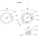
- FIG. 1 shows a conventional coaxial cable 100 and two exemplary cables of the present invention, 200 and 300.
- a coaxial cable is made, generally, of three separate spaces: a metallic inner conductor 110, a metallic outer conductor 130, and a space between them.
- the space between them is usually filled with a low-loss dielectric material 120 (e.g., polytetrafluorethylen, or PTFE) to mechanically support the inner conductor and maintain it with the outer conductor.
- the characteristic impedance of a coaxial cable is fixed by the ratio of diameters of the inner conductor and dielectric material (i.e., inner diameter of the outer conductor) and the permittivity of the space between them.
- the permittivity is fixed because of the solid polymer comprising it.
- a fluid with variable permittivity (or conductivity) at least partially occupies this space, permitting the characteristic impedance of the cable to be adjusted.
- the coaxial cable 200 has the outer portion of the dielectric material removed to create a channel between the dielectric material 120 and the outer conductor 130.
- the created space is separated into four distinct channels 150 by the addition of support lines 140 configured to maintain the space between the outer conductor 130 and the solid dielectric material 120.
- the support lines 140 may be made of any desired material and may be the same or a different material as the solid dielectric material 120.
- the presence of multiple channels permits one or more of the channels to permit flow in one direction (towards the proximal end of the cable) and one or more other channels to permit flow in the opposite direction (towards the distal end of the cable).
- the coaxial cable 300 has a substantial portion of the solid dielectric material 120 removed.
- Such an embodiment may be generated, for example, by stripping away the solid dielectric material 120 down to the surface of inner conductor 110 on each of four sides.
- strips of dielectric material 120 are applied to an inner conductor 110 to create the structure.
- four channels 150 are created.
- the diameter of the outer conductor 130 is substantially reduced.
- the corners provided by the remaining dielectric material 120 provide the support to maintain the position of the outer conductor 130 with respect to the inner conductor 110.
- the overall diameter of the coaxial cable 300 and the device is substantially reduced.
- the present invention provides devices configured to circulate coolant materials for purposes of sinking heat away from the cable itself, and thereby reducing unwanted heating of the medium (e.g., tissue).
- Exemplary coolant fluids include, but are not limited to, one or more of or combinations of, water, glycol, air, inert gasses, carbon dioxide, nitrogen, helium, sulfur hexafluoride, ionic solutions (e.g., sodium chloride with or without potassium and other ions), dextrose in water, Ringer's lactate, organic chemical solutions (e.g., ethylene glycol, diethylene glycol, or propylene glycol), oils (e.g., mineral oils, silicone oils, fluorocarbon oils), liquid metals, freons, halomethanes, liquified propane, other haloalkanes, anhydrous ammonia, sulfur dioxide.
- ionic solutions e.g., sodium chloride with or without potassium and other ions
- dextrose in water Ringer's lactate
- organic chemical solutions e.g., ethylene glycol, diethylene glycol, or propy
- cooling occurs, at least in part, by changing concentrations of coolant, pressure, or volume.
- cooling can be achieved via gas coolants using the Joule-Thompson effect.
- the cooling is provided by a chemical reaction.
- the devices are not limited to a particular type of temperature reducing chemical reaction.
- the temperature reducing chemical reaction is an endothermic reaction.
- the devices are not limited to a particular manner of applying endothermic reactions for purposes of preventing undesired heating.
- first and second chemicals are flowed into the device such that they react to reduce the temperature of the device.
- the device is prepared with the first and second chemicals preloaded in the device.
- the chemicals are separated by a barrier that is removed when desired.
- the barrier is configured to melt upon exposure to a predetermined temperature or temperature range.
- the device initiates the endothermic reaction only upon reaching a heat level that merits cooling.
- multiple different barriers are located throughout the device such that local cooling occurs only at those portions of the device where undesired heating is occurring.
- the barriers used are beads that encompass one of the two chemicals.
- the barriers are walls (e.g., discs in the shape of washers) that melt to combine the two chemicals.
- the barriers are made of wax that is configured to melt at a predetermined temperature.
- the devices are not limited to a particular type, kind or amount of meltable material.
- the meltable material is biocompatible.
- the devices are not limited to a particular type, kind, or amount of first and second chemicals, so long as their mixture results in a temperature reducing chemical reaction.
- the first material includes barium hydroxide octahydrate crystals and the second material is dry ammonium chloride.
- the first material is water and the second material is ammonium chloride.
- the first material is thionyl chloride (SOCl 2 ) and the second material is cobalt(II) sulfate heptahydrate.
- the first material is water and the second material is ammonium nitrate.
- the first material is water and the second material is potassium chloride.
- the first material is ethanoic acid and the second material is sodium carbonate.
- a meltable material is used that, itself, reduces heat by melting an flowing in a manner such that the heat at the outer surface of the device is reduced.
- Figures 2 , 3 , and 7 show device embodiments configured to provide this benefit.
- Figure 2 shows a coaxial cable 400 comprising an outer conductor 401, and an inner conductor 402 that may be extended from the end of the device to deliver energy to a target tissue.
- the solid dielectric material 403 has a channel carved therein 404 that permits fluid flow down the longitudinal length of the coaxial cable 400 to the feed point of the antenna.
- a small transverse channel 405 is provided to allow fluid flow back through a different channel (not shown).
- a fluid reservoir is provided instead of the small transverse channel.
- a fluid reservoir can be created, for example, by removing the dielectric material of the coaxial cable at the location where the cooling channel terminates.
- Figure 3 shows a cut-away view of a coaxial cable 500 with an inner conductor 502 covered by a coating 503 contained within a solid dielectric material 501.
- Two channels 504 are cut through the interior of the dielectric material 501 to permit flow of fluid.
- a small transverse channel 505 is provided to allow fluid flow between the two channels.
- Figures 7A -F show a series of cross-sectional views of cables 750 having an inner conductor 760, a dielectric material 765, a middle coaxial shield 770 (shown as a thin film or foil in 7D and E), and an outer conductor 775.
- Figures 7A -E show the coaxial cable 750 having therein gap areas 780 in between the middle coaxial shield 770 and the outer conductor 775.
- Figure 7F shows the coaxial cable 750 having therein gap areas 780 within the outer conductor 775.
- the gap areas 780 may be used for circulating a coolant material.
- such a coaxial cable may have only one gap area, while in other embodiments, as shown in Figures 7B and 7F , there are two segregated gap areas.
- Such a configuration as shown in Figures 7B and/or 7F permit the input of coolant material through one of the gap areas and the output of the inputted coolant material through the other gap area.
- Such a configuration as shown in Figure 7B permits the input of coolant material through one of the gap areas and the output of the inputted coolant material through the other gap area.
- channels are created by deforming an otherwise circular assembly comprising an inner conductor, dielectric material and middle coaxial shield.
- the channels are created by filling the space between with the coaxial shield and the outer conductor with a material and removing a portion of the material to create a channel.
- the material is a curable material and strips of the material are cured by providing heat along the length of the exterior surface of the outer conductor to create thin, cured strips. The uncured material is then removed, to create channels that are separated by the barriers of cured material.
- the coaxial cable 750 has therein at least one coolant tube 785 positioned within the gap areas 780.
- the present invention is not limited to a particular type or kind of coolant tube 785.
- the composition of the coolant tube 785 is metal, plastic, ceramic, Kevlar, etc.
- the coolant tube 785 is a deformable tube capable of assuming a variety of shapes and configurations (e.g., a Kapton Tube).
- the coolant tube 785 is temperature resistant.
- the coolant tube(s) 785 is positioned such that it does not effect the thickness of the middle coaxial shield 770 or the outer conductor 775.
- the coolant tube(s) 785 is positioned such that it encroaches upon the middle coaxial shield 770 thereby reducing the thickness of the middle coaxial shield 770 at the location of encroachment.
- the coolant tube(s) is positioned such that it encroaches upon the middle coaxial shield 770 and the outer conductor 775 thereby reducing the thickness of the middle coaxial shield 770 and the outer conductor 775 at the location of encroachment.
- the coolant tube(s) is positioned such that it encroaches upon only the outer conductor 775 thereby reducing the thickness of the outer conductor 775 at the location of encroachment.
- a coolant material may be inputted through the coolant tube 785 and outputted through the gap area 780, or the coolant material inputted through the gap area 780 and outputted through the coolant tube 785.
- two coolant tubes 785 are positioned within the gap area 780.
- the coolant material may be inputted through the two coolant tubes 785 and outputted through the gap area 780, or the coolant material inputted through one of the coolant tubes 785 and outputted through the second coolant tube 785, or the coolant material inputted through the gap area 780, and outputted through the coolant tubes 785.
- a plurality of coolant tubes 785 are positioned along the outside of the middle coaxial shield 770.
- any number (e.g., 1, 2, 5, 10) of the coolant tubes 785 may be used to input the coolant material and any number (e.g., 1, 2, 5, 10) of the coolant tubes 785 may be used to output the coolant material.
- half of the coolant tubes 785 are used to input coolant material and half of the coolant tubes 785 are used to output coolant material.
- the gap area 780 may be used to input or output coolant material.
- the coolant tubes 785 are conductive and replace the outer conductor.
- a thin non-conductive sheath 790 encases the device.
- the coaxial cable prevents unwanted heating along the length of the coaxial cable through the positioning of a plurality of coolant tubes along the exterior of the outer conductor.
- Figure 7F provides one such example.
- channels are provided in the outer conductor.
- channels e.g., tubing
- the device may be covered in a sheath (e.g., shrink-wrap material) to securely hold the channels to the outside of the outer conductor.
- sheath e.g., shrink-wrap material
- the device has a handle attached with the device, wherein the handle is configured to, for example, control the passing of coolant into and out of the coolant channels and/or coolant tubes.
- the handle is also connected to coolant and energy delivery systems via one or more cables.
- a single cable connects the energy delivery system (e.g., generator) and coolant system to the handle.
- the cable is attached to the handle at a 90-degree angle or approximately a 90-degree angle.
- the coolant handling system is provided to manage the flow of coolant to the device.
- the coolant handling system is manually controlled.
- the coolant handling system is automatically controlled.
- the temperature of returning coolant is monitored and the temperature is used to determine flow rate of input coolant.
- the energy delivery is also control based on temperature of one or more portions of the device.
- An automated or partially automated system may control a wide variety of operations. For example, in some embodiments, when the device is ready for operation, the automated system primes the cooling system by circulating coolant or another material through the coolant passageways. Once the system is primed, the program enters a normal coolant management protocol.
- one or more temperature sensors that monitor temperature of the coolant, one or more portions of the device, or the surrounding tissue, are used to control coolant flow and/or energy delivery.
- the temperature of the tip or antenna is monitored to make sure it is sufficiently high (e.g., before starting a procedure or before activating the energy delivery mode), while the temperature of the feed line or handle is monitored to maintain a portion of the device at sufficiently low temperature to avoid tissue damage proximal to the treated region.
- the impedance of the device connected to the end of the coaxial cable can also be variable. There are many instances for which this is true, including: a device whose input impedance changes with temperature (e.g., a resonant antenna in a medium of changing permittivity, as in microwave ablation), whose impedance changes over time, changed based on loading further downstream in the network, etc. In these instances, it may be beneficial to change the impedance of the coaxial line feeding these devices.
- a microwave ablation antenna at the end of a coaxial cable may resonate inside the tissue at an initial temperature, T 0 . As the tissue warms, the input impedance and, thus, the resonant frequency of the antenna shift along with the dielectric properties of the tissue.
- This shift causes an impedance mismatch between the feeding coaxial cable and the antenna, which results in reflections from the antenna. This, in turn, results in reduced efficiency in the antenna, less of the desired tissue heating effect and more of the undesirable heating of the feed cable and peripheral tissue proximal to the antenna.
- the present invention provides means for providing this matching by altering the fluid passed through the channels to adjust the characteristic impedance.
- the present invention also provides means for reducing the undesired heating by flowing coolant though the channels.
- kits comprising one or more of a generator, a power distribution system, and an applicator device, along with any one or more accessory agents (e.g., surgical instruments, software for assisting in procedure, processors, temperature monitoring devices, etc.).
- accessory agents e.g., surgical instruments, software for assisting in procedure, processors, temperature monitoring devices, etc.
- the present invention is not limited to any particular accessory agent.
- kits comprising instructions (e.g., ablation instructions, pharmaceutical instructions) along with the systems and devices of the present invention and/or a pharmaceutical agent (e.g., a sedating medication, a topical antiseptic, a topical anesthesia).
- the devices of the present invention may be used in any medical procedure (e.g., percutaneous or surgical) involving delivery of energy (e.g., microwave energy) to a tissue region.
- energy e.g., microwave energy
- the present invention is not limited to a particular type or kind of tissue region (e.g., brain, liver, heart, blood vessels, foot, lung, bone, etc.).
- the systems of the present invention find use in ablating tumor regions.
- the applicator device is inserted into, for example, a subject such that the distal end of the distal coaxial outer shield is positioned in the vicinity of the desired tissue region.
- the generator is used to provide a desired amount of microwave energy to the power distribution system at a characteristic impedance level, which in turn provides the energy at a characteristic impedance level to the applicator device.
- the distal coaxial center conductor is extended from the distal coaxial outer shield in a manner retaining the characteristic impedance level.
- a desired amount of microwave energy is delivered to the desired tissue region (e.g., tumor) generating an electric field of sufficient strength to ablate the desired tissue region. Due to the characteristic impedance level maintained throughout the transmission lines of the applicator device, the overall temperature of the transmission lines is greatly reduced, resulting in a reduced chance for undesired tissue overheating.
- the devices may be used in methods involving the simultaneous use of multiple (e.g., two or more) applicator devices for the treatment of a tissue.
- the devices may also be used in methods wherein the simultaneous use of multiple antennas are phased to achieve constructive and destructive interference (e.g., for purposes of selectively destroying and sparing portions of a tissue region).
- the present invention further provides software for regulating the amount of microwave energy provided to a tissue region through monitoring of the temperature of the tissue region (e.g., through a feedback system).
- the software is configured to interact with the systems for microwave therapy of the present invention such that it is able to raise or lower (e.g., tune) the amount of energy delivered to a tissue region.
- the type of tissue being treated e.g., liver
- the software is inputted into the software for purposes of allowing the software to regulate (e.g., tune) the delivery of microwave energy to the tissue region based upon pre-calibrated methods for that particular type of tissue region.
- the software provides a chart or diagram based upon a particular type of tissue region displaying characteristics useful to a user of the system.
- the software provides energy delivering algorithms for purposes of, for example, slowly ramping power to avoid tissue cracking due to rapid out-gassing created by high temperatures.
- the software allows a user to choose power, duration of treatment, different treatment algorithms for different tissue types, simultaneous application of power to the antennas in multiple antenna mode, switched power delivery between antennas, coherent and incoherent phasing, etc.
- the software is configured for imaging equipment (e.g., computerized tomography (CT), magnetic resonance imaging (MRI), ultrasound).
- imaging equipment software allows a user to make predictions based upon known thermodynamic and electrical properties of tissue and location of the antenna(s).
- the imaging software allows the generation of a three-dimensional map of the location of a tissue region (e.g., tumor, arrhythmia), location of the antenna(s), and to generate a predicted map of the ablation zone.
Landscapes
- Health & Medical Sciences (AREA)
- Surgery (AREA)
- Life Sciences & Earth Sciences (AREA)
- Biomedical Technology (AREA)
- Medical Informatics (AREA)
- Nuclear Medicine, Radiotherapy & Molecular Imaging (AREA)
- Electromagnetism (AREA)
- Engineering & Computer Science (AREA)
- Physics & Mathematics (AREA)
- Heart & Thoracic Surgery (AREA)
- Otolaryngology (AREA)
- Molecular Biology (AREA)
- Animal Behavior & Ethology (AREA)
- General Health & Medical Sciences (AREA)
- Public Health (AREA)
- Veterinary Medicine (AREA)
- Surgical Instruments (AREA)
Claims (9)
- Dispositif configuré pour délivrer de l'énergie à un tissu, dans lequel ledit dispositif comprend :
une partie de ligne d'alimentation (200, 400, 500, 750) présentant un diamètre extérieur qui est inférieur ou égal à une aiguille de calibre 16 et comprenant :un conducteur interne (110, 402, 502, 760) et un conducteur externe (130, 401, 775) séparés par un matériau diélectrique (120, 403, 501, 765) ;un espace situé entre le matériau diélectrique et le conducteur externe ;une pluralité de lignes de support (140) situées dans ledit espace pour fournir un support pour maintenir la position du conducteur externe (130) par rapport au conducteur interne (110) ; etun passage de fluide de refroidissement (404, 504, 780) situé à l'intérieur dudit diamètre extérieur, dans lequel le passage de fluide de refroidissement comprend une pluralité de canaux (150) formés dans ledit espace par lesdites lignes de support, etune partie d'antenne distale par rapport à ladite partie de ligne d'alimentation (200, 300, 400, 500, 750) . - Dispositif selon la revendication 1, dans lequel ledit diamètre extérieur est inférieur ou égal à une aiguille de calibre 17 ou est inférieur ou égal à une aiguille de calibre 20.
- Dispositif selon la revendication 1, dans lequel ladite énergie est une énergie de microondes.
- Dispositif selon la revendication 3, dans lequel ledit passage de fluide de refroidissement (404, 504, 780) se termine de préférence à l'intérieur de ladite partie de ligne d'alimentation (200, 300, 400, 500, 750).
- Dispositif selon la revendication 1, dans lequel le passage de fluide de refroidissement est configuré de telle sorte que le fluide de refroidissement n'entre pas en contact avec ladite partie d'antenne.
- Dispositif selon la revendication 1, comprenant en outre une pointe à son extrémité distale.
- Dispositif selon la revendication 1, dans lequel ledit passage de fluide de refroidissement (404, 504, 780) est configuré de telle sorte que, lorsque du fluide de refroidissement est présent dans le passage (404, 504, 780), le fluide de refroidissement modifie une impédance caractéristique du dispositif comparativement au dispositif en l'absence du fluide de refroidissement.
- Dispositif selon la revendication 1, dans lequel le passage de fluide de refroidissement (404, 504, 780) comprend deux ou plusieurs canaux (150).
- Dispositif selon la revendication 8, dans lequel ledit dispositif est configuré pour transférer un fluide de refroidissement dans une première direction à travers un premier desdits deux ou plusieurs canaux (150) et dans une seconde direction à travers un second desdits deux ou plusieurs canaux (150).
Priority Applications (1)
| Application Number | Priority Date | Filing Date | Title |
|---|---|---|---|
| EP20207852.3A EP3797721A1 (fr) | 2006-03-24 | 2007-03-26 | Ligne de transmission avec capacité de transfert de chaleur |
Applications Claiming Priority (2)
| Application Number | Priority Date | Filing Date | Title |
|---|---|---|---|
| US78546706P | 2006-03-24 | 2006-03-24 | |
| PCT/US2007/007408 WO2007112081A1 (fr) | 2006-03-24 | 2007-03-26 | Ligne de transmission avec capacité de transfert de chaleur |
Related Child Applications (2)
| Application Number | Title | Priority Date | Filing Date |
|---|---|---|---|
| EP20207852.3A Division EP3797721A1 (fr) | 2006-03-24 | 2007-03-26 | Ligne de transmission avec capacité de transfert de chaleur |
| EP20207852.3A Division-Into EP3797721A1 (fr) | 2006-03-24 | 2007-03-26 | Ligne de transmission avec capacité de transfert de chaleur |
Publications (2)
| Publication Number | Publication Date |
|---|---|
| EP1998698A1 EP1998698A1 (fr) | 2008-12-10 |
| EP1998698B1 true EP1998698B1 (fr) | 2020-12-23 |
Family
ID=38294225
Family Applications (2)
| Application Number | Title | Priority Date | Filing Date |
|---|---|---|---|
| EP07753988.0A Active EP1998698B1 (fr) | 2006-03-24 | 2007-03-26 | Ligne de transmission avec capacité de transfert de chaleur |
| EP20207852.3A Pending EP3797721A1 (fr) | 2006-03-24 | 2007-03-26 | Ligne de transmission avec capacité de transfert de chaleur |
Family Applications After (1)
| Application Number | Title | Priority Date | Filing Date |
|---|---|---|---|
| EP20207852.3A Pending EP3797721A1 (fr) | 2006-03-24 | 2007-03-26 | Ligne de transmission avec capacité de transfert de chaleur |
Country Status (3)
| Country | Link |
|---|---|
| US (2) | US10363092B2 (fr) |
| EP (2) | EP1998698B1 (fr) |
| WO (1) | WO2007112081A1 (fr) |
Families Citing this family (63)
| Publication number | Priority date | Publication date | Assignee | Title |
|---|---|---|---|---|
| US20060276781A1 (en) * | 2004-04-29 | 2006-12-07 | Van Der Weide Daniel W | Cannula cooling and positioning device |
| US20070055224A1 (en) * | 2004-04-29 | 2007-03-08 | Lee Fred T Jr | Intralumenal microwave device |
| WO2006127847A2 (fr) * | 2005-05-24 | 2006-11-30 | Micrablate, Llc | Dispositif chirurgical a ondes millimetriques |
| WO2006138382A2 (fr) | 2005-06-14 | 2006-12-28 | Micrablate, Llc | Outil de resection de tissus a ondes millimetriques |
| WO2007112102A1 (fr) | 2006-03-24 | 2007-10-04 | Micrablate | Dipôle à alimentation centrale destiné à être utilisé avec des systèmes, des dispositifs, et des procédés d'ablation tissulaire |
| EP1998698B1 (fr) | 2006-03-24 | 2020-12-23 | Neuwave Medical, Inc. | Ligne de transmission avec capacité de transfert de chaleur |
| US10376314B2 (en) | 2006-07-14 | 2019-08-13 | Neuwave Medical, Inc. | Energy delivery systems and uses thereof |
| US11389235B2 (en) * | 2006-07-14 | 2022-07-19 | Neuwave Medical, Inc. | Energy delivery systems and uses thereof |
| EP3626194A1 (fr) * | 2006-07-14 | 2020-03-25 | Neuwave Medical, Inc. | Système de distribution d'énergie |
| US20090082762A1 (en) * | 2007-09-20 | 2009-03-26 | Ormsby Theodore C | Radio frequency energy transmission device for the ablation of biological tissues |
| US8280525B2 (en) | 2007-11-16 | 2012-10-02 | Vivant Medical, Inc. | Dynamically matched microwave antenna for tissue ablation |
| US8945111B2 (en) | 2008-01-23 | 2015-02-03 | Covidien Lp | Choked dielectric loaded tip dipole microwave antenna |
| US7642451B2 (en) | 2008-01-23 | 2010-01-05 | Vivant Medical, Inc. | Thermally tuned coaxial cable for microwave antennas |
| GB2457299B (en) * | 2008-02-09 | 2013-04-24 | Uk Investments Associates Llc | Microwave applicator |
| GB2496788B (en) * | 2008-02-09 | 2013-07-10 | Uk Investments Associates Llc | Method of forming a microwave applicator |
| US8965536B2 (en) | 2008-03-03 | 2015-02-24 | Covidien Lp | Intracooled percutaneous microwave ablation probe |
| US9173706B2 (en) | 2008-08-25 | 2015-11-03 | Covidien Lp | Dual-band dipole microwave ablation antenna |
| US8251987B2 (en) | 2008-08-28 | 2012-08-28 | Vivant Medical, Inc. | Microwave antenna |
| US20100071883A1 (en) * | 2008-09-08 | 2010-03-25 | Jan Vetrovec | Heat transfer device |
| CN103006322A (zh) * | 2009-02-05 | 2013-04-03 | 英国投资联合公司 | 微波发生器 |
| US8728068B2 (en) * | 2009-04-09 | 2014-05-20 | Urologix, Inc. | Cooled antenna for device insertable into a body |
| US8934989B2 (en) * | 2009-04-15 | 2015-01-13 | Medwaves, Inc. | Radio frequency based ablation system and method with dielectric transformer |
| AU2010247874B2 (en) | 2009-05-11 | 2015-05-14 | TriAgenics, Inc. | Therapeutic tooth bud ablation |
| WO2014143014A1 (fr) | 2013-03-15 | 2014-09-18 | Triagenics, Llc | Ablation thérapeutique de bourgeon dentaire |
| EP2859862B1 (fr) * | 2009-07-28 | 2017-06-14 | Neuwave Medical, Inc. | Dispositif d'ablation |
| US8355803B2 (en) | 2009-09-16 | 2013-01-15 | Vivant Medical, Inc. | Perfused core dielectrically loaded dipole microwave antenna probe |
| US8551083B2 (en) | 2009-11-17 | 2013-10-08 | Bsd Medical Corporation | Microwave coagulation applicator and system |
| US9993294B2 (en) * | 2009-11-17 | 2018-06-12 | Perseon Corporation | Microwave coagulation applicator and system with fluid injection |
| US8414570B2 (en) * | 2009-11-17 | 2013-04-09 | Bsd Medical Corporation | Microwave coagulation applicator and system |
| US20110125148A1 (en) * | 2009-11-17 | 2011-05-26 | Turner Paul F | Multiple Frequency Energy Supply and Coagulation System |
| KR101902350B1 (ko) * | 2010-01-29 | 2018-10-01 | 스미스 앤드 네퓨, 인크. | 십자인대-보존 무릎 보철물 |
| EP3804651A1 (fr) | 2010-05-03 | 2021-04-14 | Neuwave Medical, Inc. | Systèmes de distribution d'énergie |
| US8652127B2 (en) | 2010-05-26 | 2014-02-18 | Covidien Lp | System and method for chemically cooling an ablation antenna |
| US8740893B2 (en) | 2010-06-30 | 2014-06-03 | Covidien Lp | Adjustable tuning of a dielectrically loaded loop antenna |
| US8376948B2 (en) | 2011-02-17 | 2013-02-19 | Vivant Medical, Inc. | Energy-delivery device including ultrasound transducer array and phased antenna array |
| US8317703B2 (en) | 2011-02-17 | 2012-11-27 | Vivant Medical, Inc. | Energy-delivery device including ultrasound transducer array and phased antenna array, and methods of adjusting an ablation field radiating into tissue using same |
| EP2793726B1 (fr) | 2011-12-21 | 2020-09-30 | Neuwave Medical, Inc. | Systèmes de distribution d'énergie |
| US20130281851A1 (en) * | 2012-04-19 | 2013-10-24 | Kenneth L. Carr | Heating/sensing catheter apparatus for minimally invasive applications |
| US9119650B2 (en) | 2013-03-15 | 2015-09-01 | Covidien Lp | Microwave energy-delivery device and system |
| US9301723B2 (en) | 2013-03-15 | 2016-04-05 | Covidien Lp | Microwave energy-delivery device and system |
| US9161814B2 (en) | 2013-03-15 | 2015-10-20 | Covidien Lp | Microwave energy-delivery device and system |
| JP6707036B2 (ja) | 2014-07-02 | 2020-06-10 | コヴィディエン リミテッド パートナーシップ | アラインメント |
| EP3164075B1 (fr) | 2014-07-02 | 2021-03-24 | Covidien LP | Système de coordonnées unifié pour scans tdm multiples de poumons de patient |
| US10624697B2 (en) | 2014-08-26 | 2020-04-21 | Covidien Lp | Microwave ablation system |
| US10813691B2 (en) | 2014-10-01 | 2020-10-27 | Covidien Lp | Miniaturized microwave ablation assembly |
| GB201418479D0 (en) | 2014-10-17 | 2014-12-03 | Creo Medical Ltd | Cable for conveying radiofrequency and/or microwave frequency energy to an electrosurgical instrument |
| WO2017075068A1 (fr) | 2015-10-26 | 2017-05-04 | Neuwave Medical, Inc. | Appareils pour maintenir un dispositif médical et leurs procédés associés |
| CN113367788B (zh) | 2015-10-26 | 2024-09-06 | 纽韦弗医疗设备公司 | 能量递送系统及其用途 |
| US10813692B2 (en) | 2016-02-29 | 2020-10-27 | Covidien Lp | 90-degree interlocking geometry for introducer for facilitating deployment of microwave radiating catheter |
| CN109069203B (zh) | 2016-04-15 | 2021-06-22 | 纽韦弗医疗设备公司 | 用于能量输送的系统和方法 |
| US20170319267A1 (en) * | 2016-05-05 | 2017-11-09 | Covidien Lp | Ablation instruments with a member having a triangular cross-section |
| US11464576B2 (en) | 2018-02-09 | 2022-10-11 | Covidien Lp | System and method for displaying an alignment CT |
| US20190246876A1 (en) | 2018-02-15 | 2019-08-15 | Neuwave Medical, Inc. | Compositions and methods for directing endoscopic devices |
| US11672596B2 (en) | 2018-02-26 | 2023-06-13 | Neuwave Medical, Inc. | Energy delivery devices with flexible and adjustable tips |
| KR20210103494A (ko) | 2018-12-13 | 2021-08-23 | 뉴웨이브 메디컬, 인코포레이티드 | 에너지 전달 장치 및 관련 시스템 |
| GB201901211D0 (en) * | 2019-01-29 | 2019-03-20 | Emblation Ltd | Microwave apparatus and method |
| US11832879B2 (en) | 2019-03-08 | 2023-12-05 | Neuwave Medical, Inc. | Systems and methods for energy delivery |
| EP4413935A3 (fr) | 2019-06-06 | 2024-09-18 | TriAgenics, Inc. | Systèmes de sonde d'ablation |
| WO2021102239A1 (fr) * | 2019-11-20 | 2021-05-27 | Kammio, Inc. | Dispositifs et procédés d'ablation thérapeutique par hyperfréquences |
| WO2021108704A1 (fr) * | 2019-11-27 | 2021-06-03 | Blossom Innovations, LLC | Dispositifs, systèmes et procédés d'analyse de tissue, de détermination d'emplacement et d'ablation de tissu |
| US20230346472A1 (en) * | 2020-05-04 | 2023-11-02 | The Regents Of The University Of California | Apparatus and Systems for Liquid Metal-Based Tunable Coaxial Antenna for Microwave Ablation |
| CN113739831A (zh) * | 2021-07-28 | 2021-12-03 | 广西电网有限责任公司南宁供电局 | 一种输电线路集成传感器监测主机 |
| WO2023180355A1 (fr) * | 2022-03-24 | 2023-09-28 | Huber+Suhner Ag | Ensemble câble |
Citations (4)
| Publication number | Priority date | Publication date | Assignee | Title |
|---|---|---|---|---|
| US20050245919A1 (en) * | 2004-04-29 | 2005-11-03 | Van Der Weide Daniel W | Triaxial antenna for microwave tissue ablation |
| WO2006002943A1 (fr) * | 2004-07-02 | 2006-01-12 | Microsulis Limited | Applicateur de rayonnement et procede d'irradiation de tissus |
| WO2007112103A1 (fr) * | 2006-03-24 | 2007-10-04 | Neuwave Medical, Inc. | Système de fourniture d'énergie |
| WO2008008545A2 (fr) * | 2006-07-14 | 2008-01-17 | Micrablate | Systèmes de distribution d'énergie et utilisations |
Family Cites Families (385)
| Publication number | Priority date | Publication date | Assignee | Title |
|---|---|---|---|---|
| US530099A (en) * | 1894-12-04 | Directory-post and call-box | ||
| US3800552A (en) * | 1972-03-29 | 1974-04-02 | Bendix Corp | Cryogenic surgical instrument |
| US3838242A (en) * | 1972-05-25 | 1974-09-24 | Hogle Kearns Int | Surgical instrument employing electrically neutral, d.c. induced cold plasma |
| US3991770A (en) * | 1974-01-24 | 1976-11-16 | Leveen Harry H | Method for treating benign and malignant tumors utilizing radio frequency, electromagnetic radiation |
| US4057064A (en) * | 1976-01-16 | 1977-11-08 | Valleylab, Inc. | Electrosurgical method and apparatus for initiating an electrical discharge in an inert gas flow |
| US4074718A (en) * | 1976-03-17 | 1978-02-21 | Valleylab, Inc. | Electrosurgical instrument |
| FR2421628A1 (fr) * | 1977-04-08 | 1979-11-02 | Cgr Mev | Dispositif de chauffage localise utilisant des ondes electromagnetiques de tres haute frequence, pour applications medicales |
| US4557272A (en) * | 1980-03-31 | 1985-12-10 | Microwave Associates, Inc. | Microwave endoscope detection and treatment system |
| US4375220A (en) * | 1980-05-09 | 1983-03-01 | Matvias Fredrick M | Microwave applicator with cooling mechanism for intracavitary treatment of cancer |
| US4446874A (en) * | 1981-12-30 | 1984-05-08 | Clini-Therm Corporation | Microwave applicator with discoupled input coupling and frequency tuning functions |
| JPS58173540A (ja) | 1982-04-03 | 1983-10-12 | 銭谷 利男 | マイクロ波手術装置 |
| US5370675A (en) * | 1992-08-12 | 1994-12-06 | Vidamed, Inc. | Medical probe device and method |
| JPS5957650A (ja) * | 1982-09-27 | 1984-04-03 | 呉羽化学工業株式会社 | 腔内加熱用プロ−ブ |
| US4534347A (en) * | 1983-04-08 | 1985-08-13 | Research Corporation | Microwave coagulating scalpel |
| GB2139500B (en) * | 1983-05-14 | 1986-07-30 | Hpw Ltd | Surgical laser knives |
| US4589424A (en) * | 1983-08-22 | 1986-05-20 | Varian Associates, Inc | Microwave hyperthermia applicator with variable radiation pattern |
| US4601296A (en) * | 1983-10-07 | 1986-07-22 | Yeda Research And Development Co., Ltd. | Hyperthermia apparatus |
| USRE33791E (en) | 1984-07-05 | 1992-01-07 | M/A-Com, Inc. | Non-invasive temperature monitor |
| US4586491A (en) | 1984-12-14 | 1986-05-06 | Warner-Lambert Technologies, Inc. | Bronchoscope with small gauge viewing attachment |
| GB2171309B (en) * | 1985-02-26 | 1988-11-02 | North China Res I Electro Opti | Microwave therapeutic apparatus |
| US4712559A (en) * | 1985-06-28 | 1987-12-15 | Bsd Medical Corporation | Local current capacitive field applicator for interstitial array |
| US4643186A (en) * | 1985-10-30 | 1987-02-17 | Rca Corporation | Percutaneous transluminal microwave catheter angioplasty |
| US4641649A (en) * | 1985-10-30 | 1987-02-10 | Rca Corporation | Method and apparatus for high frequency catheter ablation |
| US4700716A (en) * | 1986-02-27 | 1987-10-20 | Kasevich Associates, Inc. | Collinear antenna array applicator |
| US4901719A (en) * | 1986-04-08 | 1990-02-20 | C. R. Bard, Inc. | Electrosurgical conductive gas stream equipment |
| US4790311A (en) * | 1986-06-03 | 1988-12-13 | Ruiz Oscar F | Radio frequency angioplasty catheter system |
| US4860752A (en) * | 1988-02-18 | 1989-08-29 | Bsd Medical Corporation | Invasive microwave array with destructive and coherent phase |
| EP0415997A4 (en) * | 1988-05-18 | 1992-04-08 | Kasevich Associates, Inc. | Microwave balloon angioplasty |
| US5074861A (en) * | 1988-05-23 | 1991-12-24 | Schneider Richard T | Medical laser device and method |
| US4880015A (en) | 1988-06-03 | 1989-11-14 | Nierman David M | Biopsy forceps |
| US5344435A (en) * | 1988-07-28 | 1994-09-06 | Bsd Medical Corporation | Urethral inserted applicator prostate hyperthermia |
| US5150717A (en) | 1988-11-10 | 1992-09-29 | Arye Rosen | Microwave aided balloon angioplasty with guide filament |
| US5026959A (en) * | 1988-11-16 | 1991-06-25 | Tokyo Keiki Co. Ltd. | Microwave radiator for warming therapy |
| FR2639238B1 (fr) | 1988-11-21 | 1991-02-22 | Technomed Int Sa | Appareil de traitement chirurgical de tissus par hyperthermie, de preference la prostate, comprenant des moyens de protection thermique comprenant de preference des moyens formant ecran radioreflechissant |
| US4945912A (en) * | 1988-11-25 | 1990-08-07 | Sensor Electronics, Inc. | Catheter with radiofrequency heating applicator |
| US4974587A (en) * | 1988-12-22 | 1990-12-04 | Bsd Medical Corporation | Applicator array and positioning system for hyperthermia |
| US5057104A (en) * | 1989-05-30 | 1991-10-15 | Cyrus Chess | Method and apparatus for treating cutaneous vascular lesions |
| US5007437A (en) * | 1989-06-16 | 1991-04-16 | Mmtc, Inc. | Catheters for treating prostate disease |
| DE3926934A1 (de) * | 1989-08-16 | 1991-02-21 | Deutsches Krebsforsch | Hyperthermie-mikrowellenapplikator zur erwaermung einer begrenzten umgebung in einem dissipativen medium |
| US5697375A (en) * | 1989-09-18 | 1997-12-16 | The Research Foundation Of State University Of New York | Method and apparatus utilizing heart sounds for determining pressures associated with the left atrium |
| US5167619A (en) * | 1989-11-17 | 1992-12-01 | Sonokineticss Group | Apparatus and method for removal of cement from bone cavities |
| US5211625A (en) * | 1990-03-20 | 1993-05-18 | Olympus Optical Co., Ltd. | Ultrasonic treatment apparatus |
| US5098429A (en) * | 1990-04-17 | 1992-03-24 | Mmtc, Inc. | Angioplastic technique employing an inductively-heated ferrite material |
| US5213561A (en) | 1990-09-06 | 1993-05-25 | Weinstein Joseph S | Method and devices for preventing restenosis after angioplasty |
| DE9190129U1 (de) | 1990-09-14 | 1993-07-01 | American Medical Systems, Inc., Minnetonka, Minn. | Kombinierter Hyperthermie- und Dilatations-Katheter |
| US5409453A (en) | 1992-08-12 | 1995-04-25 | Vidamed, Inc. | Steerable medical probe with stylets |
| JP3091253B2 (ja) * | 1991-04-25 | 2000-09-25 | オリンパス光学工業株式会社 | 温熱治療装置 |
| US5301687A (en) | 1991-06-06 | 1994-04-12 | Trustees Of Dartmouth College | Microwave applicator for transurethral hyperthermia |
| US5597146A (en) | 1991-08-05 | 1997-01-28 | Putman; J. Michael | Rail-mounted stabilizer for surgical instrument |
| WO1993009845A1 (fr) | 1991-11-12 | 1993-05-27 | Trustees Of Dartmouth College | Procede et systeme d'hyperthermie par micro-onde |
| US5344418A (en) * | 1991-12-12 | 1994-09-06 | Shahriar Ghaffari | Optical system for treatment of vascular lesions |
| US5295955A (en) * | 1992-02-14 | 1994-03-22 | Amt, Inc. | Method and apparatus for microwave aided liposuction |
| US5300099A (en) | 1992-03-06 | 1994-04-05 | Urologix, Inc. | Gamma matched, helical dipole microwave antenna |
| US5413588A (en) | 1992-03-06 | 1995-05-09 | Urologix, Inc. | Device and method for asymmetrical thermal therapy with helical dipole microwave antenna |
| US5599352A (en) | 1992-03-19 | 1997-02-04 | Medtronic, Inc. | Method of making a drug eluting stent |
| WO1993020768A1 (fr) | 1992-04-13 | 1993-10-28 | Ep Technologies, Inc. | Ensemble antenne micro-ondes orientable pour l'ablation de tissus dans le c×ur |
| US5281217A (en) * | 1992-04-13 | 1994-01-25 | Ep Technologies, Inc. | Steerable antenna systems for cardiac ablation that minimize tissue damage and blood coagulation due to conductive heating patterns |
| US5314466A (en) | 1992-04-13 | 1994-05-24 | Ep Technologies, Inc. | Articulated unidirectional microwave antenna systems for cardiac ablation |
| US5281213A (en) * | 1992-04-16 | 1994-01-25 | Implemed, Inc. | Catheter for ice mapping and ablation |
| US5755752A (en) | 1992-04-24 | 1998-05-26 | Segal; Kim Robin | Diode laser irradiation system for biological tissue stimulation |
| US5277201A (en) * | 1992-05-01 | 1994-01-11 | Vesta Medical, Inc. | Endometrial ablation apparatus and method |
| US5275597A (en) * | 1992-05-18 | 1994-01-04 | Baxter International Inc. | Percutaneous transluminal catheter and transmitter therefor |
| US5248312A (en) * | 1992-06-01 | 1993-09-28 | Sensor Electronics, Inc. | Liquid metal-filled balloon |
| US5720718A (en) | 1992-08-12 | 1998-02-24 | Vidamed, Inc. | Medical probe apparatus with enhanced RF, resistance heating, and microwave ablation capabilities |
| US5643175A (en) | 1992-09-01 | 1997-07-01 | Adair; Edwin L. | Sterilizable endoscope with separable disposable tube assembly |
| JP3421038B2 (ja) | 1992-09-01 | 2003-06-30 | エドウィン エル アデアー, | 分離可能の使い捨て管組立体を有する滅菌可能の内視鏡 |
| US5369251A (en) * | 1992-09-14 | 1994-11-29 | Kdc Technology Corp. | Microwave interstitial hyperthermia probe |
| US5620479A (en) | 1992-11-13 | 1997-04-15 | The Regents Of The University Of California | Method and apparatus for thermal therapy of tumors |
| US5348554A (en) * | 1992-12-01 | 1994-09-20 | Cardiac Pathways Corporation | Catheter for RF ablation with cooled electrode |
| DE9301616U1 (de) * | 1993-02-05 | 1994-06-01 | W.L. Gore & Associates Gmbh, 85640 Putzbrunn | Flexibler Katheter |
| US5575794A (en) | 1993-02-12 | 1996-11-19 | Walus; Richard L. | Tool for implanting a fiducial marker |
| US5405346A (en) | 1993-05-14 | 1995-04-11 | Fidus Medical Technology Corporation | Tunable microwave ablation catheter |
| US5364392A (en) * | 1993-05-14 | 1994-11-15 | Fidus Medical Technology Corporation | Microwave ablation catheter system with impedance matching tuner and method |
| US5693082A (en) | 1993-05-14 | 1997-12-02 | Fidus Medical Technology Corporation | Tunable microwave ablation catheter system and method |
| US5462556A (en) * | 1993-06-24 | 1995-10-31 | Powers; William J. | Ectoparasite remover and method for removing an ectoparasite from a host organism |
| GB9315473D0 (en) | 1993-07-27 | 1993-09-08 | Chemring Ltd | Treatment apparatus |
| US5431649A (en) * | 1993-08-27 | 1995-07-11 | Medtronic, Inc. | Method and apparatus for R-F ablation |
| US5540649A (en) | 1993-10-08 | 1996-07-30 | Leonard Medical, Inc. | Positioner for medical instruments |
| US5507743A (en) | 1993-11-08 | 1996-04-16 | Zomed International | Coiled RF electrode treatment apparatus |
| US5788694A (en) * | 1993-12-08 | 1998-08-04 | Vancaillie; Thierry G. | Self-guiding electrode for tissue resection |
| US6530922B2 (en) | 1993-12-15 | 2003-03-11 | Sherwood Services Ag | Cluster ablation electrode system |
| US6241725B1 (en) | 1993-12-15 | 2001-06-05 | Sherwood Services Ag | High frequency thermal ablation of cancerous tumors and functional targets with image data assistance |
| US6044846A (en) | 1994-06-24 | 2000-04-04 | Edwards; Stuart D. | Method to treat esophageal sphincters |
| US6056744A (en) | 1994-06-24 | 2000-05-02 | Conway Stuart Medical, Inc. | Sphincter treatment apparatus |
| US6002968A (en) | 1994-06-24 | 1999-12-14 | Vidacare, Inc. | Uterine treatment apparatus |
| US5456684A (en) * | 1994-09-08 | 1995-10-10 | Hutchinson Technology Incorporated | Multifunctional minimally invasive surgical instrument |
| US5531739A (en) * | 1994-09-23 | 1996-07-02 | Coherent, Inc. | Method of treating veins |
| US6694163B1 (en) | 1994-10-27 | 2004-02-17 | Wake Forest University Health Sciences | Method and system for producing interactive, three-dimensional renderings of selected body organs having hollow lumens to enable simulated movement through the lumen |
| US5559295A (en) | 1994-12-01 | 1996-09-24 | Sheryll; Richard P. | Underwater sampling method and apparatus |
| US5603697A (en) | 1995-02-14 | 1997-02-18 | Fidus Medical Technology Corporation | Steering mechanism for catheters and methods for making same |
| US6106524A (en) | 1995-03-03 | 2000-08-22 | Neothermia Corporation | Methods and apparatus for therapeutic cauterization of predetermined volumes of biological tissue |
| US5647871A (en) | 1995-03-10 | 1997-07-15 | Microsurge, Inc. | Electrosurgery with cooled electrodes |
| US5688267A (en) | 1995-05-01 | 1997-11-18 | Ep Technologies, Inc. | Systems and methods for sensing multiple temperature conditions during tissue ablation |
| US6575969B1 (en) | 1995-05-04 | 2003-06-10 | Sherwood Services Ag | Cool-tip radiofrequency thermosurgery electrode system for tumor ablation |
| DE69635423T2 (de) | 1995-05-04 | 2006-06-08 | Sherwood Services Ag | Thermochirurgiesystem mit kalter elektrospitze |
| US5697949A (en) * | 1995-05-18 | 1997-12-16 | Symbiosis Corporation | Small diameter endoscopic instruments |
| US5769879A (en) | 1995-06-07 | 1998-06-23 | Medical Contouring Corporation | Microwave applicator and method of operation |
| US5788692A (en) | 1995-06-30 | 1998-08-04 | Fidus Medical Technology Corporation | Mapping ablation catheter |
| US5810804A (en) | 1995-08-15 | 1998-09-22 | Rita Medical Systems | Multiple antenna ablation apparatus and method with cooling element |
| US5782827A (en) | 1995-08-15 | 1998-07-21 | Rita Medical Systems, Inc. | Multiple antenna ablation apparatus and method with multiple sensor feedback |
| US5849029A (en) | 1995-12-26 | 1998-12-15 | Esc Medical Systems, Ltd. | Method for controlling the thermal profile of the skin |
| US5716389A (en) | 1995-11-13 | 1998-02-10 | Walinsky; Paul | Cardiac ablation catheter arrangement with movable guidewire |
| DE19609831A1 (de) * | 1996-03-13 | 1997-09-18 | Philips Patentverwaltung | Schaltungsanordnung zum Liefern eines Gleichstromes |
| US6258083B1 (en) | 1996-03-29 | 2001-07-10 | Eclipse Surgical Technologies, Inc. | Viewing surgical scope for minimally invasive procedures |
| US6302880B1 (en) | 1996-04-08 | 2001-10-16 | Cardima, Inc. | Linear ablation assembly |
| US5904709A (en) | 1996-04-17 | 1999-05-18 | The United States Of America As Represented By The Administrator Of The National Aeronautics And Space Administration | Microwave treatment for cardiac arrhythmias |
| US6898454B2 (en) * | 1996-04-25 | 2005-05-24 | The Johns Hopkins University | Systems and methods for evaluating the urethra and the periurethral tissues |
| AUPN957296A0 (en) * | 1996-04-30 | 1996-05-23 | Cardiac Crc Nominees Pty Limited | A system for simultaneous unipolar multi-electrode ablation |
| US6449507B1 (en) | 1996-04-30 | 2002-09-10 | Medtronic, Inc. | Method and system for nerve stimulation prior to and during a medical procedure |
| US7022105B1 (en) | 1996-05-06 | 2006-04-04 | Novasys Medical Inc. | Treatment of tissue in sphincters, sinuses and orifices |
| EP0837716A1 (fr) | 1996-05-06 | 1998-04-29 | Thermal Therapeutics, Inc. | Applicateur intra-uterin a travers le col pour hyperthermie intra-uterine |
| US5776129A (en) | 1996-06-12 | 1998-07-07 | Ethicon Endo-Surgery, Inc. | Endometrial ablation apparatus and method |
| US5776176A (en) | 1996-06-17 | 1998-07-07 | Urologix Inc. | Microwave antenna for arterial for arterial microwave applicator |
| US6102885A (en) * | 1996-08-08 | 2000-08-15 | Bass; Lawrence S. | Device for suction-assisted lipectomy and method of using same |
| US5800494A (en) | 1996-08-20 | 1998-09-01 | Fidus Medical Technology Corporation | Microwave ablation catheters having antennas with distal fire capabilities |
| US5759200A (en) | 1996-09-04 | 1998-06-02 | Azar; Zion | Method of selective photothermolysis |
| US5737384A (en) | 1996-10-04 | 1998-04-07 | Massachusetts Institute Of Technology | X-ray needle providing heating with microwave energy |
| US5741249A (en) | 1996-10-16 | 1998-04-21 | Fidus Medical Technology Corporation | Anchoring tip assembly for microwave ablation catheter |
| US5810803A (en) | 1996-10-16 | 1998-09-22 | Fidus Medical Technology Corporation | Conformal positioning assembly for microwave ablation catheter |
| US6719755B2 (en) | 1996-10-22 | 2004-04-13 | Epicor Medical, Inc. | Methods and devices for ablation |
| US6091995A (en) * | 1996-11-08 | 2000-07-18 | Surx, Inc. | Devices, methods, and systems for shrinking tissues |
| US6073052A (en) | 1996-11-15 | 2000-06-06 | Zelickson; Brian D. | Device and method for treatment of gastroesophageal reflux disease |
| US6235022B1 (en) * | 1996-12-20 | 2001-05-22 | Cardiac Pathways, Inc | RF generator and pump apparatus and system and method for cooled ablation |
| US5910104A (en) | 1996-12-26 | 1999-06-08 | Cryogen, Inc. | Cryosurgical probe with disposable sheath |
| JP3417778B2 (ja) | 1997-01-17 | 2003-06-16 | ペンタックス株式会社 | 内視鏡用処置具 |
| US6083255A (en) | 1997-04-07 | 2000-07-04 | Broncus Technologies, Inc. | Bronchial stenter |
| ES2353846T3 (es) | 1997-04-11 | 2011-03-07 | United States Surgical Corporation | Aparato para ablación con rf y controlador del mismo. |
| US6223085B1 (en) | 1997-05-06 | 2001-04-24 | Urologix, Inc. | Device and method for preventing restenosis |
| US6012457A (en) | 1997-07-08 | 2000-01-11 | The Regents Of The University Of California | Device and method for forming a circumferential conduction block in a pulmonary vein |
| US6086529A (en) | 1997-05-13 | 2000-07-11 | Wisconsin Medical, Inc. | Bronchoscopic manifold with compressible diaphragmatic valve for simultaneous airway instrumentation |
| JP4056091B2 (ja) | 1997-05-15 | 2008-03-05 | パロマー・メディカル・テクノロジーズ・インコーポレーテッド | 皮膚科的治療方法及び装置 |
| US6514249B1 (en) | 1997-07-08 | 2003-02-04 | Atrionix, Inc. | Positioning system and method for orienting an ablation element within a pulmonary vein ostium |
| US6500174B1 (en) | 1997-07-08 | 2002-12-31 | Atrionix, Inc. | Circumferential ablation device assembly and methods of use and manufacture providing an ablative circumferential band along an expandable member |
| US6869431B2 (en) | 1997-07-08 | 2005-03-22 | Atrionix, Inc. | Medical device with sensor cooperating with expandable member |
| US6104959A (en) | 1997-07-31 | 2000-08-15 | Microwave Medical Corp. | Method and apparatus for treating subcutaneous histological features |
| US6273885B1 (en) | 1997-08-16 | 2001-08-14 | Cooltouch Corporation | Handheld photoepilation device and method |
| US6246784B1 (en) | 1997-08-19 | 2001-06-12 | The United States Of America As Represented By The Department Of Health And Human Services | Method for segmenting medical images and detecting surface anomalies in anatomical structures |
| DE19739699A1 (de) | 1997-09-04 | 1999-03-11 | Laser & Med Tech Gmbh | Elektrodenanordnung zur elektro-thermischen Behandlung des menschlichen oder tierischen Körpers |
| US5891114A (en) | 1997-09-30 | 1999-04-06 | Target Therapeutics, Inc. | Soft-tip high performance braided catheter |
| US5995875A (en) | 1997-10-01 | 1999-11-30 | United States Surgical | Apparatus for thermal treatment of tissue |
| US6120496A (en) | 1998-05-05 | 2000-09-19 | Scimed Life Systems, Inc. | Surgical method and apparatus for positioning a diagnostic or therapeutic element within the body and coupling device for use with same |
| AU1198199A (en) * | 1997-10-29 | 1999-05-17 | Bisco, Inc. | Dental composite light curing system |
| US6310629B1 (en) | 1997-12-19 | 2001-10-30 | Texas Instruments Incorporated | System and method for advanced interfaces for virtual environments |
| US6582486B1 (en) * | 1997-12-30 | 2003-06-24 | Pirelli Ambient S.P.A. | Solid combustible composition |
| US7016811B2 (en) | 2001-08-15 | 2006-03-21 | National Instruments Corporation | Network-based system for configuring a programmable hardware element in a measurement system using hardware configuration programs generated based on a user specification |
| US6273886B1 (en) | 1998-02-19 | 2001-08-14 | Curon Medical, Inc. | Integrated tissue heating and cooling apparatus |
| US20030135206A1 (en) | 1998-02-27 | 2003-07-17 | Curon Medical, Inc. | Method for treating a sphincter |
| WO1999051157A1 (fr) | 1998-04-07 | 1999-10-14 | The General Hospital Corporation | Appareil et procedes d'elimination de vaisseaux sanguins |
| US6210323B1 (en) | 1998-05-05 | 2001-04-03 | The University Of British Columbia | Surgical arm and tissue stabilizer |
| US6635055B1 (en) | 1998-05-06 | 2003-10-21 | Microsulis Plc | Microwave applicator for endometrial ablation |
| GB9809536D0 (en) | 1998-05-06 | 1998-07-01 | Microsulis Plc | Sensor positioning |
| US6127450A (en) * | 1998-06-09 | 2000-10-03 | Kerr Corporation | Dental restorative composite |
| US6251128B1 (en) | 1998-09-01 | 2001-06-26 | Fidus Medical Technology Corporation | Microwave ablation catheter with loop configuration |
| US6016811A (en) | 1998-09-01 | 2000-01-25 | Fidus Medical Technology Corporation | Method of using a microwave ablation catheter with a loop configuration |
| WO2000015297A1 (fr) | 1998-09-11 | 2000-03-23 | Medivance, Inc. | Procede et appareil servant a assurer un chauffage localise de l'hypothalamus anterieur preoptique |
| WO2000018191A1 (fr) * | 1998-09-18 | 2000-03-30 | Marc Seghatol | Systeme de polarisation par micro-ondes en dentisterie |
| US6602227B1 (en) | 1998-09-25 | 2003-08-05 | Sherwood Services Ag | Surgical system console |
| US6245062B1 (en) | 1998-10-23 | 2001-06-12 | Afx, Inc. | Directional reflector shield assembly for a microwave ablation instrument |
| US6067475A (en) | 1998-11-05 | 2000-05-23 | Urologix, Inc. | Microwave energy delivery system including high performance dual directional coupler for precisely measuring forward and reverse microwave power during thermal therapy |
| US6451015B1 (en) * | 1998-11-18 | 2002-09-17 | Sherwood Services Ag | Method and system for menu-driven two-dimensional display lesion generator |
| US6190382B1 (en) | 1998-12-14 | 2001-02-20 | Medwaves, Inc. | Radio-frequency based catheter system for ablation of body tissues |
| US20070066972A1 (en) | 2001-11-29 | 2007-03-22 | Medwaves, Inc. | Ablation catheter apparatus with one or more electrodes |
| US7731677B2 (en) | 1999-01-19 | 2010-06-08 | Olympus Corporation | Ultrasonic surgical system |
| US6097985A (en) | 1999-02-09 | 2000-08-01 | Kai Technologies, Inc. | Microwave systems for medical hyperthermia, thermotherapy and diagnosis |
| US6427089B1 (en) | 1999-02-19 | 2002-07-30 | Edward W. Knowlton | Stomach treatment apparatus and method |
| GB9904373D0 (en) | 1999-02-25 | 1999-04-21 | Microsulis Plc | Radiation applicator |
| US6398781B1 (en) | 1999-03-05 | 2002-06-04 | Gyrus Medical Limited | Electrosurgery system |
| US20020022836A1 (en) * | 1999-03-05 | 2002-02-21 | Gyrus Medical Limited | Electrosurgery system |
| US6287297B1 (en) | 1999-03-05 | 2001-09-11 | Plc Medical Systems, Inc. | Energy delivery system and method for performing myocardial revascular |
| US6161049A (en) | 1999-03-26 | 2000-12-12 | Urologix, Inc. | Thermal therapy catheter |
| US6962586B2 (en) | 1999-05-04 | 2005-11-08 | Afx, Inc. | Microwave ablation instrument with insertion probe |
| US6325796B1 (en) * | 1999-05-04 | 2001-12-04 | Afx, Inc. | Microwave ablation instrument with insertion probe |
| US7226446B1 (en) | 1999-05-04 | 2007-06-05 | Dinesh Mody | Surgical microwave ablation assembly |
| US6461352B2 (en) * | 1999-05-11 | 2002-10-08 | Stryker Corporation | Surgical handpiece with self-sealing switch assembly |
| US6277113B1 (en) | 1999-05-28 | 2001-08-21 | Afx, Inc. | Monopole tip for ablation catheter and methods for using same |
| US6287302B1 (en) | 1999-06-14 | 2001-09-11 | Fidus Medical Technology Corporation | End-firing microwave ablation instrument with horn reflection device |
| US6306132B1 (en) | 1999-06-17 | 2001-10-23 | Vivant Medical | Modular biopsy and microwave ablation needle delivery apparatus adapted to in situ assembly and method of use |
| US6464625B2 (en) | 1999-06-23 | 2002-10-15 | Robert A. Ganz | Therapeutic method and apparatus for debilitating or killing microorganisms within the body |
| US6246905B1 (en) | 1999-07-30 | 2001-06-12 | Jamil Ahmad Mogul | Medical instrument that supplies multiple energy forms |
| US6749606B2 (en) | 1999-08-05 | 2004-06-15 | Thomas Keast | Devices for creating collateral channels |
| US6230060B1 (en) * | 1999-10-22 | 2001-05-08 | Daniel D. Mawhinney | Single integrated structural unit for catheter incorporating a microwave antenna |
| US7097641B1 (en) | 1999-12-09 | 2006-08-29 | Cryocath Technologies Inc. | Catheter with cryogenic and heating ablation |
| US6347251B1 (en) | 1999-12-23 | 2002-02-12 | Tianquan Deng | Apparatus and method for microwave hyperthermia and acupuncture |
| US7033352B1 (en) | 2000-01-18 | 2006-04-25 | Afx, Inc. | Flexible ablation instrument |
| US6435872B1 (en) * | 2000-02-02 | 2002-08-20 | Bisco, Inc. | Tapered light probe with non-circular output for a dental light curing unit |
| US6770070B1 (en) | 2000-03-17 | 2004-08-03 | Rita Medical Systems, Inc. | Lung treatment apparatus and method |
| US6869430B2 (en) | 2000-03-31 | 2005-03-22 | Rita Medical Systems, Inc. | Tissue biopsy and treatment apparatus and method |
| US6673068B1 (en) | 2000-04-12 | 2004-01-06 | Afx, Inc. | Electrode arrangement for use in a medical instrument |
| US6471696B1 (en) | 2000-04-12 | 2002-10-29 | Afx, Inc. | Microwave ablation instrument with a directional radiation pattern |
| US6638277B2 (en) | 2000-07-06 | 2003-10-28 | Scimed Life Systems, Inc. | Tumor ablation needle with independently activated and independently traversing tines |
| CA2416581A1 (fr) | 2000-07-25 | 2002-04-25 | Rita Medical Systems, Inc. | Appareil pour detecter et traiter des tumeurs par une mesure d'impedance localisee |
| US6942661B2 (en) | 2000-08-30 | 2005-09-13 | Boston Scientific Scimed, Inc. | Fluid cooled apparatus for supporting diagnostic and therapeutic elements in contact with tissue |
| US6866624B2 (en) | 2000-12-08 | 2005-03-15 | Medtronic Ave,Inc. | Apparatus and method for treatment of malignant tumors |
| US20020173780A1 (en) * | 2001-03-02 | 2002-11-21 | Altshuler Gregory B. | Apparatus and method for photocosmetic and photodermatological treatment |
| US6666579B2 (en) | 2000-12-28 | 2003-12-23 | Ge Medical Systems Global Technology Company, Llc | Method and apparatus for obtaining and displaying computed tomography images using a fluoroscopy imaging system |
| US20020087151A1 (en) * | 2000-12-29 | 2002-07-04 | Afx, Inc. | Tissue ablation apparatus with a sliding ablation instrument and method |
| US20030083654A1 (en) | 2000-12-29 | 2003-05-01 | Afx, Inc. | Tissue ablation system with a sliding ablating device and method |
| AU2002245243B2 (en) | 2001-01-11 | 2007-03-22 | Angiodynamics, Inc. | Bone-treatment instrument and method |
| US6546077B2 (en) | 2001-01-17 | 2003-04-08 | Medtronic Ave, Inc. | Miniature X-ray device and method of its manufacture |
| US6699240B2 (en) | 2001-04-26 | 2004-03-02 | Medtronic, Inc. | Method and apparatus for tissue ablation |
| US6972016B2 (en) | 2001-05-01 | 2005-12-06 | Cardima, Inc. | Helically shaped electrophysiology catheter |
| US6593395B2 (en) * | 2001-05-16 | 2003-07-15 | Kerr Corporation | Dental composition containing discrete nanoparticles |
| US6890968B2 (en) * | 2001-05-16 | 2005-05-10 | Kerr Corporation | Prepolymerized filler in dental restorative composite |
| US7324104B1 (en) | 2001-09-14 | 2008-01-29 | The Research Foundation Of State University Of New York | Method of centerline generation in virtual objects |
| JP2005502417A (ja) * | 2001-09-19 | 2005-01-27 | ウロロジックス, インコーポレイテッド | マイクロ波アブレーションデバイス |
| US20030060813A1 (en) * | 2001-09-22 | 2003-03-27 | Loeb Marvin P. | Devices and methods for safely shrinking tissues surrounding a duct, hollow organ or body cavity |
| ATE320767T1 (de) | 2001-09-28 | 2006-04-15 | Rita Medical Systems Inc | Impedanzgesteuerte vorrichtung zur ablation von gewebe |
| US6585733B2 (en) | 2001-09-28 | 2003-07-01 | Ethicon, Inc. | Surgical treatment for atrial fibrillation using radiofrequency technology |
| US6878147B2 (en) | 2001-11-02 | 2005-04-12 | Vivant Medical, Inc. | High-strength microwave antenna assemblies |
| US7128739B2 (en) | 2001-11-02 | 2006-10-31 | Vivant Medical, Inc. | High-strength microwave antenna assemblies and methods of use |
| FR2832516B1 (fr) * | 2001-11-19 | 2004-01-23 | Tokendo Sarl | Endoscopes rotatifs a visee distale deviee |
| US6709271B2 (en) * | 2001-11-20 | 2004-03-23 | Bisco, Inc. | Low shrinkage dental composite |
| CA2468531C (fr) | 2001-11-29 | 2010-06-01 | Medwaves, Inc. | Systeme de catheter a radiofrequence avec mecanismes de deviation et de guidage ameliores |
| US6849075B2 (en) * | 2001-12-04 | 2005-02-01 | Estech, Inc. | Cardiac ablation devices and methods |
| US6740107B2 (en) | 2001-12-19 | 2004-05-25 | Trimedyne, Inc. | Device for treatment of atrioventricular valve regurgitation |
| US6817999B2 (en) | 2002-01-03 | 2004-11-16 | Afx, Inc. | Flexible device for ablation of biological tissue |
| US6893436B2 (en) | 2002-01-03 | 2005-05-17 | Afx, Inc. | Ablation instrument having a flexible distal portion |
| US6813515B2 (en) | 2002-01-04 | 2004-11-02 | Dune Medical Devices Ltd. | Method and system for examining tissue according to the dielectric properties thereof |
| US20050075629A1 (en) * | 2002-02-19 | 2005-04-07 | Afx, Inc. | Apparatus and method for assessing tissue ablation transmurality |
| US6702576B2 (en) * | 2002-02-22 | 2004-03-09 | Ultradent Products, Inc. | Light-curing device with detachably interconnecting light applicator |
| US9364281B2 (en) | 2002-03-05 | 2016-06-14 | Avent, Inc. | Methods for treating the thoracic region of a patient's body |
| US20050177209A1 (en) | 2002-03-05 | 2005-08-11 | Baylis Medical Company Inc. | Bipolar tissue treatment system |
| US6918905B2 (en) | 2002-03-21 | 2005-07-19 | Ceramoptec Industries, Inc. | Monolithic irradiation handpiece |
| EP1496798A1 (fr) | 2002-04-10 | 2005-01-19 | Stereotaxis, Inc. | Systemes et procedes destines a des interventions medicales |
| US7197363B2 (en) | 2002-04-16 | 2007-03-27 | Vivant Medical, Inc. | Microwave antenna having a curved configuration |
| US6752767B2 (en) | 2002-04-16 | 2004-06-22 | Vivant Medical, Inc. | Localization element with energized tip |
| AU2003237802A1 (en) | 2002-04-16 | 2003-11-03 | Vivant Medical, Inc. | Localization element with energized tip |
| EP2380487B1 (fr) | 2002-04-17 | 2021-03-31 | Covidien LP | Structures d'endoscope pour se déplacer vers une cible dans une structure ramifiée |
| US6780178B2 (en) | 2002-05-03 | 2004-08-24 | The Board Of Trustees Of The Leland Stanford Junior University | Method and apparatus for plasma-mediated thermo-electrical ablation |
| US6924325B2 (en) | 2002-06-21 | 2005-08-02 | Kerr Corporation | Silver-containing dental composition |
| US20040082859A1 (en) * | 2002-07-01 | 2004-04-29 | Alan Schaer | Method and apparatus employing ultrasound energy to treat body sphincters |
| GB2390545B (en) | 2002-07-09 | 2005-04-20 | Barts & London Nhs Trust | Hollow organ probe |
| US6858025B2 (en) | 2002-08-06 | 2005-02-22 | Medically Advanced Designs, Llc | Cryo-surgical apparatus and method of use |
| US20040030367A1 (en) | 2002-08-09 | 2004-02-12 | Olympus Optical Co., Ltd. | Medical control device, control method for medical control device, medical system device and control system |
| US6837712B2 (en) * | 2002-08-23 | 2005-01-04 | Kerr Corporation | Dental restorative compositions |
| GB2387544B (en) | 2002-10-10 | 2004-03-17 | Microsulis Plc | Microwave applicator |
| US6834837B2 (en) | 2002-11-07 | 2004-12-28 | Rultract, Inc. | Surgical instrument support device and method |
| DE60309744T2 (de) | 2002-11-27 | 2007-09-20 | Medical Device Innovations Ltd., Halton | Gewebsablationsgerät |
| CN2579361Y (zh) | 2002-12-02 | 2003-10-15 | 孙良俊 | 低杆温微波穿刺治疗探头 |
| US20040116921A1 (en) | 2002-12-11 | 2004-06-17 | Marshall Sherman | Cold tip rf/ultrasonic ablation catheter |
| US6994546B2 (en) | 2002-12-18 | 2006-02-07 | Ultradent Products, Inc. | Light curing device with detachable power supply |
| US6847848B2 (en) | 2003-01-07 | 2005-01-25 | Mmtc, Inc | Inflatable balloon catheter structural designs and methods for treating diseased tissue of a patient |
| US7410484B2 (en) | 2003-01-15 | 2008-08-12 | Cryodynamics, Llc | Cryotherapy probe |
| US20040158237A1 (en) * | 2003-02-11 | 2004-08-12 | Marwan Abboud | Multi-energy ablation station |
| US10172538B2 (en) | 2003-02-21 | 2019-01-08 | 3Dt Holdings, Llc | Body lumen junction localization |
| US7473219B1 (en) | 2003-03-07 | 2009-01-06 | Glenn Joshua P | Flexible fiber optic bronchoscope one-way valve |
| USD507649S1 (en) | 2003-03-21 | 2005-07-19 | Microsulis Limited | Treatment device |
| AU2003901390A0 (en) | 2003-03-26 | 2003-04-10 | University Of Technology, Sydney | Microwave antenna for cardiac ablation |
| US7153298B1 (en) | 2003-03-28 | 2006-12-26 | Vandolay, Inc. | Vascular occlusion systems and methods |
| US20040199154A1 (en) | 2003-04-02 | 2004-10-07 | Cryocath Technologies Inc. | Device for tissue ablation |
| US20050107870A1 (en) * | 2003-04-08 | 2005-05-19 | Xingwu Wang | Medical device with multiple coating layers |
| USD493531S1 (en) | 2003-04-17 | 2004-07-27 | Microsulis Limited | Treatment device probe |
| US7263997B2 (en) | 2003-05-06 | 2007-09-04 | Kimberly-Clark Worldwide, Inc | Respiratory apparatus having an instrument introduction section and manifold |
| US7641668B2 (en) | 2003-05-16 | 2010-01-05 | Scimed Life Systems, Inc. | Fluid delivery system and related methods of use |
| US6957108B2 (en) | 2003-06-02 | 2005-10-18 | Bsd Medical Corporation | Invasive microwave antenna array for hyperthermia and brachytherapy |
| US6932776B2 (en) | 2003-06-02 | 2005-08-23 | Meridian Medicalssystems, Llc | Method and apparatus for detecting and treating vulnerable plaques |
| GB2403148C2 (en) | 2003-06-23 | 2013-02-13 | Microsulis Ltd | Radiation applicator |
| US7207985B2 (en) * | 2003-06-25 | 2007-04-24 | Endocare, Inc. | Detachable cryosurgical probe |
| US7794454B2 (en) | 2003-07-11 | 2010-09-14 | Medtronic Cryocath Lp | Method and device for epicardial ablation |
| US7311703B2 (en) | 2003-07-18 | 2007-12-25 | Vivant Medical, Inc. | Devices and methods for cooling microwave antennas |
| AU2004279676B2 (en) | 2003-10-03 | 2011-10-13 | Uk Investment Associates Llc | Device and method for the treatment of hollow anatomical structures |
| GB2416203B (en) | 2004-07-13 | 2007-03-07 | Microsulis Ltd | Motion rate sensor |
| GB2406521B (en) | 2003-10-03 | 2007-05-09 | Microsulis Ltd | Treatment of hollow anatomical structures |
| US7266407B2 (en) | 2003-11-17 | 2007-09-04 | University Of Florida Research Foundation, Inc. | Multi-frequency microwave-induced thermoacoustic imaging of biological tissue |
| US7156842B2 (en) | 2003-11-20 | 2007-01-02 | Sherwood Services Ag | Electrosurgical pencil with improved controls |
| WO2005063137A2 (fr) | 2003-12-22 | 2005-07-14 | Ams Research Corporation | Dispositifs cryochirurgicaux pour ablation endometriale |
| US7182762B2 (en) * | 2003-12-30 | 2007-02-27 | Smith & Nephew, Inc. | Electrosurgical device |
| US7402140B2 (en) | 2004-02-12 | 2008-07-22 | Sanarus Medical, Inc. | Rotational core biopsy device with liquid cryogen adhesion probe |
| WO2005081991A2 (fr) | 2004-02-25 | 2005-09-09 | Cardio-Optics, Inc. | Procede et appareil de localisation du sinus coronaire pour la stimulation biventriculaire |
| US7127033B2 (en) * | 2004-02-28 | 2006-10-24 | Xoft, Inc. | Miniature x-ray tube cooling system |
| US7142633B2 (en) | 2004-03-31 | 2006-11-28 | General Electric Company | Enhanced X-ray imaging system and method |
| US7244254B2 (en) | 2004-04-29 | 2007-07-17 | Micrablate | Air-core microwave ablation antennas |
| US20070055224A1 (en) | 2004-04-29 | 2007-03-08 | Lee Fred T Jr | Intralumenal microwave device |
| US7467015B2 (en) | 2004-04-29 | 2008-12-16 | Neuwave Medical, Inc. | Segmented catheter for tissue ablation |
| US20050245920A1 (en) | 2004-04-30 | 2005-11-03 | Vitullo Jeffrey M | Cell necrosis apparatus with cooled microwave antenna |
| CN1296014C (zh) | 2004-06-17 | 2007-01-24 | 上海交通大学 | 水冷式射频肿瘤消融治疗系统 |
| BRPI0512880B1 (pt) | 2004-06-29 | 2020-11-03 | Tata Steel Ijmuiden Bv | tira de aço com camada de revestimento de liga de zinco, processo para galvanização de uma tira de aço e peça automotiva |
| GB2416307A (en) | 2004-07-16 | 2006-01-25 | Microsulis Ltd | Microwave applicator head with null forming conductors allowing for sensor placement |
| US20060064083A1 (en) | 2004-09-17 | 2006-03-23 | Steve Khalaj | Multi-tip probe used for an ocular procedure |
| WO2006039267A2 (fr) | 2004-09-30 | 2006-04-13 | Boston Scientific Scimed, Inc. | Systeme endoscopique multifonctionnel pour une utilisation dans des applications electrochirurgicales |
| US7282049B2 (en) | 2004-10-08 | 2007-10-16 | Sherwood Services Ag | Electrosurgical system employing multiple electrodes and method thereof |
| US20060094956A1 (en) | 2004-10-29 | 2006-05-04 | Viswanathan Raju R | Restricted navigation controller for, and methods of controlling, a remote navigation system |
| CN2753408Y (zh) | 2004-11-30 | 2006-01-25 | 南京康友微波能应用研究所 | 带有气体冷却装置的微波辐射针 |
| US7722620B2 (en) | 2004-12-06 | 2010-05-25 | Dfine, Inc. | Bone treatment systems and methods |
| US7568619B2 (en) | 2004-12-15 | 2009-08-04 | Alcon, Inc. | System and method for identifying and controlling ophthalmic surgical devices and components |
| US20060264921A1 (en) | 2004-12-29 | 2006-11-23 | Imflux Llc | Retractable Surgical Instruments |
| US20060200026A1 (en) | 2005-01-13 | 2006-09-07 | Hansen Medical, Inc. | Robotic catheter system |
| ITMO20050034A1 (it) | 2005-02-11 | 2006-08-12 | Hs Hospital Service Spa | Dispositivo a microonde per l'ablazione di tessuti. |
| US7601149B2 (en) | 2005-03-07 | 2009-10-13 | Boston Scientific Scimed, Inc. | Apparatus for switching nominal and attenuated power between ablation probes |
| US7799019B2 (en) | 2005-05-10 | 2010-09-21 | Vivant Medical, Inc. | Reinforced high strength microwave antenna |
| WO2006127847A2 (fr) | 2005-05-24 | 2006-11-30 | Micrablate, Llc | Dispositif chirurgical a ondes millimetriques |
| US7621890B2 (en) | 2005-06-09 | 2009-11-24 | Endocare, Inc. | Heat exchange catheter with multi-lumen tube having a fluid return passageway |
| WO2006138382A2 (fr) | 2005-06-14 | 2006-12-28 | Micrablate, Llc | Outil de resection de tissus a ondes millimetriques |
| GB2434314B (en) | 2006-01-03 | 2011-06-15 | Microsulis Ltd | Microwave applicator with dipole antenna |
| JP2007029457A (ja) | 2005-07-27 | 2007-02-08 | Univ Nihon | マイクロ波凝固療法用同軸アンテナ |
| WO2007031936A2 (fr) | 2005-09-13 | 2007-03-22 | Koninklijke Philips Electronics, N.V. | Production automatique de prises de vue optimales pour diagnostic par tomographie thoracique assistee par ordinateur |
| US8702694B2 (en) | 2005-11-23 | 2014-04-22 | Covidien Lp | Auto-aligning ablating device and method of use |
| US20070142852A1 (en) | 2005-12-21 | 2007-06-21 | Manoa Medical, Inc., A Delaware Corporation | Tissue cutting device |
| US7826904B2 (en) | 2006-02-07 | 2010-11-02 | Angiodynamics, Inc. | Interstitial microwave system and method for thermal treatment of diseases |
| WO2007112102A1 (fr) | 2006-03-24 | 2007-10-04 | Micrablate | Dipôle à alimentation centrale destiné à être utilisé avec des systèmes, des dispositifs, et des procédés d'ablation tissulaire |
| EP1998698B1 (fr) | 2006-03-24 | 2020-12-23 | Neuwave Medical, Inc. | Ligne de transmission avec capacité de transfert de chaleur |
| US8548562B2 (en) | 2006-04-04 | 2013-10-01 | John Trachtenberg | System and method of guided treatment within malignant prostate tissue |
| US8073551B2 (en) | 2006-04-04 | 2011-12-06 | University Health Network | Coil electrode apparatus for thermal therapy |
| US8007496B2 (en) | 2006-05-26 | 2011-08-30 | Boston Scientific Scimed, Inc. | Method of therapeutically treating tissue while preventing perfusion/ventilation of the tissue |
| US8515554B2 (en) | 2006-06-26 | 2013-08-20 | Meridian Medical Systems, Llc | Radiometric heating/sensing probe |
| US11389235B2 (en) | 2006-07-14 | 2022-07-19 | Neuwave Medical, Inc. | Energy delivery systems and uses thereof |
| US10376314B2 (en) | 2006-07-14 | 2019-08-13 | Neuwave Medical, Inc. | Energy delivery systems and uses thereof |
| US8155416B2 (en) | 2008-02-04 | 2012-04-10 | INTIO, Inc. | Methods and apparatuses for planning, performing, monitoring and assessing thermal ablation |
| WO2008030403A1 (fr) | 2006-09-02 | 2008-03-13 | Synecor, Llc | Manchons intestinaux et systèmes et procédés de déploiement associés |
| GB0620063D0 (en) | 2006-10-10 | 2006-11-22 | Medical Device Innovations Ltd | Needle structure and method of performing needle biopsies |
| GB0620058D0 (en) | 2006-10-10 | 2006-11-22 | Medical Device Innovations Ltd | Tissue measurement and ablation antenna |
| JP5258772B2 (ja) | 2006-10-10 | 2013-08-07 | メディカル・デバイス・イノベーションズ・リミテッド | マイクロ波放射線を用いた組織を処理するための装置およびアンテナ較正システムおよびその方法 |
| US20140163664A1 (en) | 2006-11-21 | 2014-06-12 | David S. Goldsmith | Integrated system for the ballistic and nonballistic infixion and retrieval of implants with or without drug targeting |
| US20100286791A1 (en) | 2006-11-21 | 2010-11-11 | Goldsmith David S | Integrated system for the ballistic and nonballistic infixion and retrieval of implants |
| US8715270B2 (en) | 2006-12-01 | 2014-05-06 | Boston Scientific Scimed, Inc. | Multi-part instrument systems and methods |
| JP4618241B2 (ja) | 2006-12-13 | 2011-01-26 | 株式会社村田製作所 | 同軸プローブ装置 |
| US20080161890A1 (en) | 2007-01-03 | 2008-07-03 | Boston Scientific Scimed, Inc. | Methods, systems, and apparatuses for protecting esophageal tissue during ablation |
| US8211099B2 (en) | 2007-01-31 | 2012-07-03 | Tyco Healthcare Group Lp | Thermal feedback systems and methods of using the same |
| NZ589685A (en) | 2007-04-19 | 2012-06-29 | Resmed Ltd | Cushion for patient breathing interface with variable density foam supported membrane |
| WO2008142686A2 (fr) | 2007-05-21 | 2008-11-27 | Uc-Care Ltd. | Sonde d'ablation |
| US7777130B2 (en) | 2007-06-18 | 2010-08-17 | Vivant Medical, Inc. | Microwave cable cooling |
| US20090005766A1 (en) | 2007-06-28 | 2009-01-01 | Joseph Brannan | Broadband microwave applicator |
| US8747398B2 (en) | 2007-09-13 | 2014-06-10 | Covidien Lp | Frequency tuning in a microwave electrosurgical system |
| US9008793B1 (en) | 2007-10-15 | 2015-04-14 | Chenes Llc | Multiple electrode radiofrequency generator |
| US8439907B2 (en) | 2007-11-07 | 2013-05-14 | Mirabilis Medica Inc. | Hemostatic tissue tunnel generator for inserting treatment apparatus into tissue of a patient |
| US8292880B2 (en) | 2007-11-27 | 2012-10-23 | Vivant Medical, Inc. | Targeted cooling of deployable microwave antenna |
| EP2080483B1 (fr) | 2008-01-17 | 2013-06-05 | Biotronik CRM Patent AG | Agencement de cathéter d'ablation et commande de refroidissement |
| US8945111B2 (en) | 2008-01-23 | 2015-02-03 | Covidien Lp | Choked dielectric loaded tip dipole microwave antenna |
| US8965536B2 (en) | 2008-03-03 | 2015-02-24 | Covidien Lp | Intracooled percutaneous microwave ablation probe |
| KR101719824B1 (ko) | 2008-05-09 | 2017-04-04 | 호라이라 인코포레이티드 | 기관지나무 치료용 시스템, 어셈블리 및 방법 |
| US20090281536A1 (en) | 2008-05-09 | 2009-11-12 | Hugh Beckman | Medical Device For Diagnosing and Treating Anomalous Tissue and Method for Doing the Same |
| US8059059B2 (en) | 2008-05-29 | 2011-11-15 | Vivant Medical, Inc. | Slidable choke microwave antenna |
| US20100045559A1 (en) | 2008-08-25 | 2010-02-25 | Vivant Medical, Inc. | Dual-Band Dipole Microwave Ablation Antenna |
| US9173706B2 (en) | 2008-08-25 | 2015-11-03 | Covidien Lp | Dual-band dipole microwave ablation antenna |
| US8251987B2 (en) | 2008-08-28 | 2012-08-28 | Vivant Medical, Inc. | Microwave antenna |
| US8403924B2 (en) | 2008-09-03 | 2013-03-26 | Vivant Medical, Inc. | Shielding for an isolation apparatus used in a microwave generator |
| US20100081928A1 (en) | 2008-09-29 | 2010-04-01 | Searete Llc, A Limited Liability Corporation Of The State Of Delaware | Histological Facilitation systems and methods |
| CN201267529Y (zh) | 2008-10-10 | 2009-07-08 | 南京福中信息产业集团有限公司 | 具有冷循环的静脉曲张治疗装置 |
| JP2012506293A (ja) | 2008-10-22 | 2012-03-15 | ミラマー ラブズ, インコーポレイテッド | マイクロ波エネルギーを用いた組織の非侵襲的処置のためのシステム、装置、方法、および手順 |
| EP2376189B1 (fr) | 2008-12-09 | 2018-02-07 | Nephera Ltd. | Stimulation de l'appareil urinaire |
| DE102009012485A1 (de) | 2009-03-12 | 2010-09-16 | Daimler Ag | Antriebsstrang für Hybridantriebe sowie Torsionsdämpfer |
| US20100268223A1 (en) | 2009-04-15 | 2010-10-21 | Tyco Health Group Lp | Methods for Image Analysis and Visualization of Medical Image Data Suitable for Use in Assessing Tissue Ablation and Systems and Methods for Controlling Tissue Ablation Using Same |
| US8934989B2 (en) | 2009-04-15 | 2015-01-13 | Medwaves, Inc. | Radio frequency based ablation system and method with dielectric transformer |
| US8235981B2 (en) | 2009-06-02 | 2012-08-07 | Vivant Medical, Inc. | Electrosurgical devices with directional radiation pattern |
| US9439735B2 (en) | 2009-06-08 | 2016-09-13 | MRI Interventions, Inc. | MRI-guided interventional systems that can track and generate dynamic visualizations of flexible intrabody devices in near real time |
| EP2442717B1 (fr) | 2009-06-16 | 2020-11-25 | ClearPoint Neuro, Inc. | Dispositifs guidés par irm et systèmes d'intervention guidés par irm qui peuvent suivre et générer des visualisations dynamiques des dispositifs presque en temps réel |
| US9226787B2 (en) | 2009-07-15 | 2016-01-05 | Uab Research Foundation | Catheter having temperature controlled anchor and related methods |
| EP2859862B1 (fr) | 2009-07-28 | 2017-06-14 | Neuwave Medical, Inc. | Dispositif d'ablation |
| EP2470080A4 (fr) | 2009-08-26 | 2017-08-30 | Carefusion 2200, Inc. | Mécanismes de positionnement et/ou de support d'instruments chirurgicaux et permettant de remplir d'autres fonctions, et leurs procédés de fabrication et leurs méthodes d'utilisation |
| US8876814B2 (en) | 2009-09-29 | 2014-11-04 | Covidien Lp | Fluid cooled choke dielectric and coaxial cable dielectric |
| US9113926B2 (en) | 2009-09-29 | 2015-08-25 | Covidien Lp | Management of voltage standing wave ratio at skin surface during microwave ablation |
| US8430871B2 (en) | 2009-10-28 | 2013-04-30 | Covidien Lp | System and method for monitoring ablation size |
| US8911439B2 (en) | 2009-11-11 | 2014-12-16 | Holaira, Inc. | Non-invasive and minimally invasive denervation methods and systems for performing the same |
| US8551083B2 (en) | 2009-11-17 | 2013-10-08 | Bsd Medical Corporation | Microwave coagulation applicator and system |
| US8454589B2 (en) | 2009-11-20 | 2013-06-04 | St. Jude Medical, Atrial Fibrillation Division, Inc. | System and method for assessing effective delivery of ablation therapy |
| US8764744B2 (en) | 2010-01-25 | 2014-07-01 | Covidien Lp | System for monitoring ablation size |
| US8617153B2 (en) | 2010-02-26 | 2013-12-31 | Covidien Lp | Tunable microwave ablation probe |
| AU2011237666A1 (en) | 2010-04-06 | 2012-11-08 | Holaira, Inc. | System and method for pulmonary treatment |
| EP3804651A1 (fr) | 2010-05-03 | 2021-04-14 | Neuwave Medical, Inc. | Systèmes de distribution d'énergie |
| US9192436B2 (en) | 2010-05-25 | 2015-11-24 | Covidien Lp | Flow rate verification monitor for fluid-cooled microwave ablation probe |
| US20120053577A1 (en) | 2010-08-25 | 2012-03-01 | Neuwave Medical, Inc. | Energy delivery systems and uses thereof |
| DE102010043574A1 (de) | 2010-11-08 | 2012-05-10 | Fresenius Medical Care Deutschland Gmbh | Manuell zu öffnender Klemmhalter mit Sensor |
| RU2013132535A (ru) | 2010-12-15 | 2015-01-20 | Конинклейке Филипс Электроникс Н.В. | Направляемое контуром совмещение деформируемого изображения |
| US9011421B2 (en) | 2011-01-05 | 2015-04-21 | Covidien Lp | Energy-delivery devices with flexible fluid-cooled shaft, inflow/outflow junctions suitable for use with same, and systems including same |
| US9017319B2 (en) | 2011-01-05 | 2015-04-28 | Covidien Lp | Energy-delivery devices with flexible fluid-cooled shaft, inflow/outflow junctions suitable for use with same, and systems including same |
| US8932281B2 (en) | 2011-01-05 | 2015-01-13 | Covidien Lp | Energy-delivery devices with flexible fluid-cooled shaft, inflow/outflow junctions suitable for use with same, and systems including same |
| US10335230B2 (en) | 2011-03-09 | 2019-07-02 | Covidien Lp | Systems for thermal-feedback-controlled rate of fluid flow to fluid-cooled antenna assembly and methods of directing energy to tissue using same |
| US20120232549A1 (en) | 2011-03-09 | 2012-09-13 | Vivant Medical, Inc. | Systems for thermal-feedback-controlled rate of fluid flow to fluid-cooled antenna assembly and methods of directing energy to tissue using same |
| US8932279B2 (en) | 2011-04-08 | 2015-01-13 | Domain Surgical, Inc. | System and method for cooling of a heated surgical instrument and/or surgical site and treating tissue |
| AU2015202149B2 (en) | 2011-04-08 | 2016-11-17 | Covidien Lp | Flexible microwave catheters for natural or artificial lumens |
| US8992413B2 (en) | 2011-05-31 | 2015-03-31 | Covidien Lp | Modified wet tip antenna design |
| DE102011078278A1 (de) | 2011-06-29 | 2013-01-03 | Siemens Aktiengesellschaft | Verfahren zur Bilderzeugung und Bildauswertung |
| US20130072924A1 (en) | 2011-09-20 | 2013-03-21 | Bsd Medical Corporation | Ablation antenna |
| EP2793726B1 (fr) | 2011-12-21 | 2020-09-30 | Neuwave Medical, Inc. | Systèmes de distribution d'énergie |
| US8968290B2 (en) | 2012-03-14 | 2015-03-03 | Covidien Lp | Microwave ablation generator control system |
| EP3639781B1 (fr) | 2012-05-18 | 2023-12-20 | Nuvaira, Inc. | Systèmes et appareils de traitement de tissus et de régulation de la sténose |
| US9121774B2 (en) | 2012-06-22 | 2015-09-01 | Covidien Lp | Microwave thermometry for microwave ablation systems |
| US9283033B2 (en) | 2012-06-30 | 2016-03-15 | Cibiem, Inc. | Carotid body ablation via directed energy |
| US9259269B2 (en) | 2012-08-07 | 2016-02-16 | Covidien Lp | Microwave ablation catheter and method of utilizing the same |
| KR101468419B1 (ko) | 2012-12-04 | 2014-12-03 | 삼성메디슨 주식회사 | 3차원 캘리퍼를 이용하여 측정 정보를 제공하는 의료 시스템 및 방법 |
| US9437036B2 (en) | 2012-12-04 | 2016-09-06 | Samsung Medison Co., Ltd. | Medical system, medical imaging apparatus, and method of providing three-dimensional marker |
| US9301723B2 (en) | 2013-03-15 | 2016-04-05 | Covidien Lp | Microwave energy-delivery device and system |
| US9119650B2 (en) | 2013-03-15 | 2015-09-01 | Covidien Lp | Microwave energy-delivery device and system |
| US20140276200A1 (en) | 2013-03-15 | 2014-09-18 | Covidien Lp | Microwave energy-delivery device and system |
| US10765477B2 (en) | 2014-03-10 | 2020-09-08 | Wisconsin Alumni Research Foundation | Microwave ablation antenna system |
-
2007
- 2007-03-26 EP EP07753988.0A patent/EP1998698B1/fr active Active
- 2007-03-26 WO PCT/US2007/007408 patent/WO2007112081A1/fr active Application Filing
- 2007-03-26 EP EP20207852.3A patent/EP3797721A1/fr active Pending
- 2007-03-26 US US11/728,460 patent/US10363092B2/en active Active
-
2019
- 2019-07-29 US US16/525,067 patent/US11944376B2/en active Active
Patent Citations (4)
| Publication number | Priority date | Publication date | Assignee | Title |
|---|---|---|---|---|
| US20050245919A1 (en) * | 2004-04-29 | 2005-11-03 | Van Der Weide Daniel W | Triaxial antenna for microwave tissue ablation |
| WO2006002943A1 (fr) * | 2004-07-02 | 2006-01-12 | Microsulis Limited | Applicateur de rayonnement et procede d'irradiation de tissus |
| WO2007112103A1 (fr) * | 2006-03-24 | 2007-10-04 | Neuwave Medical, Inc. | Système de fourniture d'énergie |
| WO2008008545A2 (fr) * | 2006-07-14 | 2008-01-17 | Micrablate | Systèmes de distribution d'énergie et utilisations |
Also Published As
| Publication number | Publication date |
|---|---|
| EP3797721A1 (fr) | 2021-03-31 |
| EP1998698A1 (fr) | 2008-12-10 |
| US11944376B2 (en) | 2024-04-02 |
| US20080033424A1 (en) | 2008-02-07 |
| US20190350652A1 (en) | 2019-11-21 |
| WO2007112081A1 (fr) | 2007-10-04 |
| US10363092B2 (en) | 2019-07-30 |
Similar Documents
| Publication | Publication Date | Title |
|---|---|---|
| US11944376B2 (en) | Transmission line with heat transfer ability | |
| US20220346873A1 (en) | Energy delivery systems and uses thereof | |
| US20230181253A1 (en) | Energy delivery systems and uses thereof | |
| US11013557B2 (en) | Energy delivery systems and uses thereof | |
| US8672932B2 (en) | Center fed dipole for use with tissue ablation systems, devices and methods | |
| US20240130782A1 (en) | Energy delivery systems and uses thereof | |
| US20070288079A1 (en) | Energy delivery system and uses thereof | |
| EP2043543B1 (fr) | Système de distribution d'énergie |
Legal Events
| Date | Code | Title | Description |
|---|---|---|---|
| PUAI | Public reference made under article 153(3) epc to a published international application that has entered the european phase |
Free format text: ORIGINAL CODE: 0009012 |
|
| 17P | Request for examination filed |
Effective date: 20081009 |
|
| AK | Designated contracting states |
Kind code of ref document: A1 Designated state(s): AT BE BG CH CY CZ DE DK EE ES FI FR GB GR HU IE IS IT LI LT LU LV MC MT NL PL PT RO SE SI SK TR |
|
| AX | Request for extension of the european patent |
Extension state: AL BA HR MK RS |
|
| RIN1 | Information on inventor provided before grant (corrected) |
Inventor name: LAESEKE, PAUL F. Inventor name: BRACE, CHRISTOPHER LEE Inventor name: LEE, FRED T. Inventor name: VAN DER WEIDE, DANIEL WARREN |
|
| RIN1 | Information on inventor provided before grant (corrected) |
Inventor name: LAESEKE, PAUL F. Inventor name: BRACE, CHRISTOPHER LEE Inventor name: LEE, FRED T. Inventor name: VAN DER WEIDE, DANIEL WARREN |
|
| RAP1 | Party data changed (applicant data changed or rights of an application transferred) |
Owner name: NEUWAVE MEDICAL, INC. |
|
| 17Q | First examination report despatched |
Effective date: 20101220 |
|
| RIC1 | Information provided on ipc code assigned before grant |
Ipc: A61B 18/18 20060101AFI20170314BHEP Ipc: A61B 18/00 20060101ALN20170314BHEP |
|
| GRAP | Despatch of communication of intention to grant a patent |
Free format text: ORIGINAL CODE: EPIDOSNIGR1 |
|
| STAA | Information on the status of an ep patent application or granted ep patent |
Free format text: STATUS: GRANT OF PATENT IS INTENDED |
|
| INTG | Intention to grant announced |
Effective date: 20170509 |
|
| GRAJ | Information related to disapproval of communication of intention to grant by the applicant or resumption of examination proceedings by the epo deleted |
Free format text: ORIGINAL CODE: EPIDOSDIGR1 |
|
| STAA | Information on the status of an ep patent application or granted ep patent |
Free format text: STATUS: EXAMINATION IS IN PROGRESS |
|
| INTC | Intention to grant announced (deleted) | ||
| GRAP | Despatch of communication of intention to grant a patent |
Free format text: ORIGINAL CODE: EPIDOSNIGR1 |
|
| STAA | Information on the status of an ep patent application or granted ep patent |
Free format text: STATUS: GRANT OF PATENT IS INTENDED |
|
| RIC1 | Information provided on ipc code assigned before grant |
Ipc: A61B 18/00 20060101ALN20171004BHEP Ipc: A61B 18/18 20060101AFI20171004BHEP |
|
| INTG | Intention to grant announced |
Effective date: 20171107 |
|
| GRAJ | Information related to disapproval of communication of intention to grant by the applicant or resumption of examination proceedings by the epo deleted |
Free format text: ORIGINAL CODE: EPIDOSDIGR1 |
|
| STAA | Information on the status of an ep patent application or granted ep patent |
Free format text: STATUS: EXAMINATION IS IN PROGRESS |
|
| GRAP | Despatch of communication of intention to grant a patent |
Free format text: ORIGINAL CODE: EPIDOSNIGR1 |
|
| INTC | Intention to grant announced (deleted) | ||
| STAA | Information on the status of an ep patent application or granted ep patent |
Free format text: STATUS: GRANT OF PATENT IS INTENDED |
|
| RIC1 | Information provided on ipc code assigned before grant |
Ipc: A61B 18/18 20060101AFI20180705BHEP Ipc: A61B 18/00 20060101ALN20180705BHEP |
|
| INTG | Intention to grant announced |
Effective date: 20180802 |
|
| GRAJ | Information related to disapproval of communication of intention to grant by the applicant or resumption of examination proceedings by the epo deleted |
Free format text: ORIGINAL CODE: EPIDOSDIGR1 |
|
| STAA | Information on the status of an ep patent application or granted ep patent |
Free format text: STATUS: EXAMINATION IS IN PROGRESS |
|
| GRAP | Despatch of communication of intention to grant a patent |
Free format text: ORIGINAL CODE: EPIDOSNIGR1 |
|
| STAA | Information on the status of an ep patent application or granted ep patent |
Free format text: STATUS: GRANT OF PATENT IS INTENDED |
|
| INTC | Intention to grant announced (deleted) | ||
| RIC1 | Information provided on ipc code assigned before grant |
Ipc: A61B 18/18 20060101AFI20190403BHEP Ipc: A61B 18/00 20060101ALN20190403BHEP |
|
| INTG | Intention to grant announced |
Effective date: 20190415 |
|
| GRAJ | Information related to disapproval of communication of intention to grant by the applicant or resumption of examination proceedings by the epo deleted |
Free format text: ORIGINAL CODE: EPIDOSDIGR1 |
|
| STAA | Information on the status of an ep patent application or granted ep patent |
Free format text: STATUS: EXAMINATION IS IN PROGRESS |
|
| GRAP | Despatch of communication of intention to grant a patent |
Free format text: ORIGINAL CODE: EPIDOSNIGR1 |
|
| STAA | Information on the status of an ep patent application or granted ep patent |
Free format text: STATUS: GRANT OF PATENT IS INTENDED |
|
| INTC | Intention to grant announced (deleted) | ||
| INTG | Intention to grant announced |
Effective date: 20190920 |
|
| RIC1 | Information provided on ipc code assigned before grant |
Ipc: A61B 18/00 20060101ALN20190911BHEP Ipc: A61B 18/18 20060101AFI20190911BHEP |
|
| GRAJ | Information related to disapproval of communication of intention to grant by the applicant or resumption of examination proceedings by the epo deleted |
Free format text: ORIGINAL CODE: EPIDOSDIGR1 |
|
| STAA | Information on the status of an ep patent application or granted ep patent |
Free format text: STATUS: EXAMINATION IS IN PROGRESS |
|
| INTC | Intention to grant announced (deleted) | ||
| GRAP | Despatch of communication of intention to grant a patent |
Free format text: ORIGINAL CODE: EPIDOSNIGR1 |
|
| STAA | Information on the status of an ep patent application or granted ep patent |
Free format text: STATUS: GRANT OF PATENT IS INTENDED |
|
| RIC1 | Information provided on ipc code assigned before grant |
Ipc: A61B 18/00 20060101ALN20200602BHEP Ipc: A61B 18/18 20060101AFI20200602BHEP |
|
| INTG | Intention to grant announced |
Effective date: 20200707 |
|
| GRAS | Grant fee paid |
Free format text: ORIGINAL CODE: EPIDOSNIGR3 |
|
| GRAA | (expected) grant |
Free format text: ORIGINAL CODE: 0009210 |
|
| STAA | Information on the status of an ep patent application or granted ep patent |
Free format text: STATUS: THE PATENT HAS BEEN GRANTED |
|
| AK | Designated contracting states |
Kind code of ref document: B1 Designated state(s): AT BE BG CH CY CZ DE DK EE ES FI FR GB GR HU IE IS IT LI LT LU LV MC MT NL PL PT RO SE SI SK TR |
|
| AX | Request for extension of the european patent |
Extension state: AL BA HR MK RS |
|
| REG | Reference to a national code |
Ref country code: GB Ref legal event code: FG4D |
|
| REG | Reference to a national code |
Ref country code: DE Ref legal event code: R096 Ref document number: 602007060858 Country of ref document: DE |
|
| REG | Reference to a national code |
Ref country code: AT Ref legal event code: REF Ref document number: 1346952 Country of ref document: AT Kind code of ref document: T Effective date: 20210115 |
|
| REG | Reference to a national code |
Ref country code: IE Ref legal event code: FG4D |
|
| PG25 | Lapsed in a contracting state [announced via postgrant information from national office to epo] |
Ref country code: FI Free format text: LAPSE BECAUSE OF FAILURE TO SUBMIT A TRANSLATION OF THE DESCRIPTION OR TO PAY THE FEE WITHIN THE PRESCRIBED TIME-LIMIT Effective date: 20201223 Ref country code: GR Free format text: LAPSE BECAUSE OF FAILURE TO SUBMIT A TRANSLATION OF THE DESCRIPTION OR TO PAY THE FEE WITHIN THE PRESCRIBED TIME-LIMIT Effective date: 20210324 |
|
| REG | Reference to a national code |
Ref country code: AT Ref legal event code: MK05 Ref document number: 1346952 Country of ref document: AT Kind code of ref document: T Effective date: 20201223 |
|
| REG | Reference to a national code |
Ref country code: NL Ref legal event code: MP Effective date: 20201223 |
|
| PG25 | Lapsed in a contracting state [announced via postgrant information from national office to epo] |
Ref country code: LV Free format text: LAPSE BECAUSE OF FAILURE TO SUBMIT A TRANSLATION OF THE DESCRIPTION OR TO PAY THE FEE WITHIN THE PRESCRIBED TIME-LIMIT Effective date: 20201223 Ref country code: SE Free format text: LAPSE BECAUSE OF FAILURE TO SUBMIT A TRANSLATION OF THE DESCRIPTION OR TO PAY THE FEE WITHIN THE PRESCRIBED TIME-LIMIT Effective date: 20201223 Ref country code: BG Free format text: LAPSE BECAUSE OF FAILURE TO SUBMIT A TRANSLATION OF THE DESCRIPTION OR TO PAY THE FEE WITHIN THE PRESCRIBED TIME-LIMIT Effective date: 20210323 |
|
| PG25 | Lapsed in a contracting state [announced via postgrant information from national office to epo] |
Ref country code: NL Free format text: LAPSE BECAUSE OF FAILURE TO SUBMIT A TRANSLATION OF THE DESCRIPTION OR TO PAY THE FEE WITHIN THE PRESCRIBED TIME-LIMIT Effective date: 20201223 |
|
| REG | Reference to a national code |
Ref country code: LT Ref legal event code: MG9D |
|
| PG25 | Lapsed in a contracting state [announced via postgrant information from national office to epo] |
Ref country code: LT Free format text: LAPSE BECAUSE OF FAILURE TO SUBMIT A TRANSLATION OF THE DESCRIPTION OR TO PAY THE FEE WITHIN THE PRESCRIBED TIME-LIMIT Effective date: 20201223 Ref country code: CZ Free format text: LAPSE BECAUSE OF FAILURE TO SUBMIT A TRANSLATION OF THE DESCRIPTION OR TO PAY THE FEE WITHIN THE PRESCRIBED TIME-LIMIT Effective date: 20201223 Ref country code: EE Free format text: LAPSE BECAUSE OF FAILURE TO SUBMIT A TRANSLATION OF THE DESCRIPTION OR TO PAY THE FEE WITHIN THE PRESCRIBED TIME-LIMIT Effective date: 20201223 Ref country code: PT Free format text: LAPSE BECAUSE OF FAILURE TO SUBMIT A TRANSLATION OF THE DESCRIPTION OR TO PAY THE FEE WITHIN THE PRESCRIBED TIME-LIMIT Effective date: 20210423 Ref country code: RO Free format text: LAPSE BECAUSE OF FAILURE TO SUBMIT A TRANSLATION OF THE DESCRIPTION OR TO PAY THE FEE WITHIN THE PRESCRIBED TIME-LIMIT Effective date: 20201223 Ref country code: SK Free format text: LAPSE BECAUSE OF FAILURE TO SUBMIT A TRANSLATION OF THE DESCRIPTION OR TO PAY THE FEE WITHIN THE PRESCRIBED TIME-LIMIT Effective date: 20201223 |
|
| PG25 | Lapsed in a contracting state [announced via postgrant information from national office to epo] |
Ref country code: PL Free format text: LAPSE BECAUSE OF FAILURE TO SUBMIT A TRANSLATION OF THE DESCRIPTION OR TO PAY THE FEE WITHIN THE PRESCRIBED TIME-LIMIT Effective date: 20201223 Ref country code: AT Free format text: LAPSE BECAUSE OF FAILURE TO SUBMIT A TRANSLATION OF THE DESCRIPTION OR TO PAY THE FEE WITHIN THE PRESCRIBED TIME-LIMIT Effective date: 20201223 |
|
| REG | Reference to a national code |
Ref country code: DE Ref legal event code: R097 Ref document number: 602007060858 Country of ref document: DE |
|
| PG25 | Lapsed in a contracting state [announced via postgrant information from national office to epo] |
Ref country code: IS Free format text: LAPSE BECAUSE OF FAILURE TO SUBMIT A TRANSLATION OF THE DESCRIPTION OR TO PAY THE FEE WITHIN THE PRESCRIBED TIME-LIMIT Effective date: 20210423 |
|
| PG25 | Lapsed in a contracting state [announced via postgrant information from national office to epo] |
Ref country code: MC Free format text: LAPSE BECAUSE OF FAILURE TO SUBMIT A TRANSLATION OF THE DESCRIPTION OR TO PAY THE FEE WITHIN THE PRESCRIBED TIME-LIMIT Effective date: 20201223 |
|
| PLBE | No opposition filed within time limit |
Free format text: ORIGINAL CODE: 0009261 |
|
| REG | Reference to a national code |
Ref country code: CH Ref legal event code: PL |
|
| STAA | Information on the status of an ep patent application or granted ep patent |
Free format text: STATUS: NO OPPOSITION FILED WITHIN TIME LIMIT |
|
| PG25 | Lapsed in a contracting state [announced via postgrant information from national office to epo] |
Ref country code: ES Free format text: LAPSE BECAUSE OF FAILURE TO SUBMIT A TRANSLATION OF THE DESCRIPTION OR TO PAY THE FEE WITHIN THE PRESCRIBED TIME-LIMIT Effective date: 20201223 Ref country code: DK Free format text: LAPSE BECAUSE OF FAILURE TO SUBMIT A TRANSLATION OF THE DESCRIPTION OR TO PAY THE FEE WITHIN THE PRESCRIBED TIME-LIMIT Effective date: 20201223 |
|
| 26N | No opposition filed |
Effective date: 20210924 |
|
| REG | Reference to a national code |
Ref country code: BE Ref legal event code: MM Effective date: 20210331 |
|
| PG25 | Lapsed in a contracting state [announced via postgrant information from national office to epo] |
Ref country code: IE Free format text: LAPSE BECAUSE OF NON-PAYMENT OF DUE FEES Effective date: 20210326 Ref country code: CH Free format text: LAPSE BECAUSE OF NON-PAYMENT OF DUE FEES Effective date: 20210331 Ref country code: LU Free format text: LAPSE BECAUSE OF NON-PAYMENT OF DUE FEES Effective date: 20210326 Ref country code: LI Free format text: LAPSE BECAUSE OF NON-PAYMENT OF DUE FEES Effective date: 20210331 |
|
| PG25 | Lapsed in a contracting state [announced via postgrant information from national office to epo] |
Ref country code: SI Free format text: LAPSE BECAUSE OF FAILURE TO SUBMIT A TRANSLATION OF THE DESCRIPTION OR TO PAY THE FEE WITHIN THE PRESCRIBED TIME-LIMIT Effective date: 20201223 |
|
| PG25 | Lapsed in a contracting state [announced via postgrant information from national office to epo] |
Ref country code: IS Free format text: LAPSE BECAUSE OF FAILURE TO SUBMIT A TRANSLATION OF THE DESCRIPTION OR TO PAY THE FEE WITHIN THE PRESCRIBED TIME-LIMIT Effective date: 20210423 |
|
| PG25 | Lapsed in a contracting state [announced via postgrant information from national office to epo] |
Ref country code: BE Free format text: LAPSE BECAUSE OF NON-PAYMENT OF DUE FEES Effective date: 20210331 |
|
| PG25 | Lapsed in a contracting state [announced via postgrant information from national office to epo] |
Ref country code: HU Free format text: LAPSE BECAUSE OF FAILURE TO SUBMIT A TRANSLATION OF THE DESCRIPTION OR TO PAY THE FEE WITHIN THE PRESCRIBED TIME-LIMIT; INVALID AB INITIO Effective date: 20070326 Ref country code: CY Free format text: LAPSE BECAUSE OF FAILURE TO SUBMIT A TRANSLATION OF THE DESCRIPTION OR TO PAY THE FEE WITHIN THE PRESCRIBED TIME-LIMIT Effective date: 20201223 |
|
| PGFP | Annual fee paid to national office [announced via postgrant information from national office to epo] |
Ref country code: DE Payment date: 20240130 Year of fee payment: 18 Ref country code: GB Payment date: 20240201 Year of fee payment: 18 |
|
| PGFP | Annual fee paid to national office [announced via postgrant information from national office to epo] |
Ref country code: IT Payment date: 20240212 Year of fee payment: 18 Ref country code: FR Payment date: 20240213 Year of fee payment: 18 |
|
| PG25 | Lapsed in a contracting state [announced via postgrant information from national office to epo] |
Ref country code: TR Free format text: LAPSE BECAUSE OF FAILURE TO SUBMIT A TRANSLATION OF THE DESCRIPTION OR TO PAY THE FEE WITHIN THE PRESCRIBED TIME-LIMIT Effective date: 20201223 |