EP1998698B1 - Transmission line with heat transfer ability - Google Patents
Transmission line with heat transfer ability Download PDFInfo
- Publication number
- EP1998698B1 EP1998698B1 EP07753988.0A EP07753988A EP1998698B1 EP 1998698 B1 EP1998698 B1 EP 1998698B1 EP 07753988 A EP07753988 A EP 07753988A EP 1998698 B1 EP1998698 B1 EP 1998698B1
- Authority
- EP
- European Patent Office
- Prior art keywords
- coolant
- energy
- tissue
- devices
- channels
- Prior art date
- Legal status (The legal status is an assumption and is not a legal conclusion. Google has not performed a legal analysis and makes no representation as to the accuracy of the status listed.)
- Active
Links
Images


Classifications
-
- A—HUMAN NECESSITIES
- A61—MEDICAL OR VETERINARY SCIENCE; HYGIENE
- A61B—DIAGNOSIS; SURGERY; IDENTIFICATION
- A61B18/00—Surgical instruments, devices or methods for transferring non-mechanical forms of energy to or from the body
- A61B18/18—Surgical instruments, devices or methods for transferring non-mechanical forms of energy to or from the body by applying electromagnetic radiation, e.g. microwaves
- A61B18/1815—Surgical instruments, devices or methods for transferring non-mechanical forms of energy to or from the body by applying electromagnetic radiation, e.g. microwaves using microwaves
-
- A—HUMAN NECESSITIES
- A61—MEDICAL OR VETERINARY SCIENCE; HYGIENE
- A61B—DIAGNOSIS; SURGERY; IDENTIFICATION
- A61B18/00—Surgical instruments, devices or methods for transferring non-mechanical forms of energy to or from the body
- A61B2018/00005—Cooling or heating of the probe or tissue immediately surrounding the probe
- A61B2018/00011—Cooling or heating of the probe or tissue immediately surrounding the probe with fluids
- A61B2018/00023—Cooling or heating of the probe or tissue immediately surrounding the probe with fluids closed, i.e. without wound contact by the fluid
-
- A—HUMAN NECESSITIES
- A61—MEDICAL OR VETERINARY SCIENCE; HYGIENE
- A61B—DIAGNOSIS; SURGERY; IDENTIFICATION
- A61B18/00—Surgical instruments, devices or methods for transferring non-mechanical forms of energy to or from the body
- A61B18/18—Surgical instruments, devices or methods for transferring non-mechanical forms of energy to or from the body by applying electromagnetic radiation, e.g. microwaves
- A61B18/1815—Surgical instruments, devices or methods for transferring non-mechanical forms of energy to or from the body by applying electromagnetic radiation, e.g. microwaves using microwaves
- A61B2018/183—Surgical instruments, devices or methods for transferring non-mechanical forms of energy to or from the body by applying electromagnetic radiation, e.g. microwaves using microwaves characterised by the type of antenna
Definitions
- the present invention relates to systems and devices for delivering energy to tissue for a wide variety of applications, including medical procedures (e.g., tissue ablation, resection, cautery, vascular thrombosis, treatment of cardiac arrhythmias and dysrhythmias, electrosurgery, tissue harvest, etc.).
- medical procedures e.g., tissue ablation, resection, cautery, vascular thrombosis, treatment of cardiac arrhythmias and dysrhythmias, electrosurgery, tissue harvest, etc.
- the present invention relates to systems and devices for the delivery of energy with heat transfer ability.
- the systems and devices also have variable characteristic impedance as a result of the use of heat transfer materials.
- Ablation is an important therapeutic strategy for treating certain tissues such as benign and malignant tumors, cardiac arrhythmias, cardiac dysrhythmias and tachycardia.
- Most approved ablation systems utilize radio frequency (RF) energy as the ablating energy source.
- RF energy has several limitations, including the rapid dissipation of energy in surface tissues resulting in shallow "burns" and failure to access deeper tumor or arrhythmic tissues.
- Another limitation of RF ablation systems is the tendency of eschar and clot formation to form on the energy emitting electrodes which limits the further deposition of electrical energy.
- Microwave energy is an effective energy source for heating biological tissues and is used in such applications as, for example, cancer treatment and preheating of blood prior to infusions. Accordingly, in view of the drawbacks of the traditional ablation techniques, there has recently been a great deal of interest in using microwave energy as an ablation energy source.
- the advantage of microwave energy over RF is the deeper penetration into tissue, insensitivity to charring, lack of necessity for grounding, more reliable energy deposition, faster tissue heating, and the capability to produce much larger thermal lesions than RF, which greatly simplifies the actual ablation procedures. Accordingly, there are a number of devices under development that utilize electromagnetic energy in the microwave frequency range as the ablation energy source (see, e.g., U.S. Patent Nos.
- Improved systems and devices for delivering energy to a tissue region are needed.
- improved systems and devices capable of delivering microwave energy without corresponding microwave energy loss are needed.
- systems and devices capable of percutaneous delivery of microwave energy to a subject's tissue without undesired tissue burning are needed.
- systems for delivery of desired amounts of microwave energy without requiring physically large invasive components are needed.
- each of various modifications of an integrated-structure inflatable balloon catheter design includes a longitudinal structure having a sharply-pointed insertion needle at a distal end of the longitudinal structure and an inflatable balloon situated intermediate a proximate end and the distal end of the longitudinal structure which is attached to said longitudinal structure.
- the insertion needle may be used to puncture the patient's skin and underlying sub-cutaneous tissue and place the deflated balloon in proximity to the diseased sub-cutaneous tissue.
- the balloon is then inflated to press against and thereby spatially deform the diseased sub-cutaneous tissue, after which the deformed diseased sub-cutaneous tissue may be therapeutically heated.
- This heating may be sufficient to cause the creation of a permanent cavity in the deformed diseased sub-cutaneous tissue which persists after the catheter is withdrawn.
- One modification employs a balloon having a selected non-uniform, odd pattern shape which, when inflated, cooperates with the shape of the diseased sub-cutaneous tissue.
- This one modification also may be beneficially used in prostate-treating balloon catheters, which do not have a sharply-pointed insertion needle at the distal end thereof.
- US 2005/015081 describes devices and methods for cooling microwave antennas.
- the cooling systems can be used with various types of microwave antennas.
- One variation generally comprises a handle portion with an elongate outer jacket extending from the handle portion.
- a microwave antenna is positioned within the handle and outer jacket such that cooling fluid pumped into the handle comes into contact directly along a portion of the length, or a majority of the length, or the entire length of the antenna to allow for direct convective cooling.
- Other variations include cooling sheaths which form defined cooling channels around a portion of the antenna.
- Yet another variation includes passively-cooled systems which utilize expandable balloons to urge tissue away from the surface of the microwave antenna as well as cooling sheaths which are cooled through endothermic chemical reactions.
- the microwave antennas themselves can have cooling lumens integrated directly therethrough.
- WO 2006/002943 describes a radiation applicator for applying electromagnetic radiation to tissue, comprising: an axial central conductor adapted to be coupled to a source of electromagnetic radiation and defining an axis; an elongate dielectric member, the dielectric member surrounding at least part of said central conductor along an axial length thereof; a metal ferrule, the ferrule being attached to the dielectric member and surrounding a portion of the central conductor and extending parallel thereto along a length thereof.
- the ferrule and the dielectric member have respective elongate cooperating surfaces and wherein the ferrule and the dielectric member are fixed to each other with said cooperating surfaces in close abutment, thereby providing a rigid structure.
- US 2005/245919 describes an improved antenna for microwave ablation uses a triaxial design which reduces reflected energy allowing higher power ablation and/or a smaller diameter feeder line to the antenna.
- Embodiments of this invention can provide devices for delivering energy to tissue for a wide variety of applications, including medical procedures (e.g., tissue ablation, resection, cautery, vascular thrombosis, intraluminal ablation of a hollow viscus, cardiac ablation for treatment of arrhythmias, electrosurgery, tissue harvest, cosmetic surgery, intraocular use, etc.).
- medical procedures e.g., tissue ablation, resection, cautery, vascular thrombosis, intraluminal ablation of a hollow viscus, cardiac ablation for treatment of arrhythmias, electrosurgery, tissue harvest, cosmetic surgery, intraocular use, etc.
- embodiments of this invention can provide devices for the delivery of energy with heat transfer ability.
- the device may also have variable characteristic impedance as a result of the use of heat transfer materials.
- Embodiments of this invention can provide a variety of heat transfer mechanisms.
- heat transfer is provided in small diameter devices.
- the outer diameter of the device is equivalent to, or smaller than, a 16-gauge needle (e.g., equal or smaller than a 17-gauge needle, a 20-gauge needle, etc.).
- Embodiments of the present invention can provide configurations of the devices that balance energy delivery, heat management, and size. Existing devices, to provide appropriate energy delivery and heat management, are large in diameter, making them undesirable or unsuitable for many applications.
- the present invention provides small diameter devices with optimized energy and heating characteristics by providing a cooling material within a coaxial or triaxial cable.
- the cooling material is provided material separating an inner and outer conductor of a coaxial cable (or central conductor of a triaxial cable), between dielectric material and outer conductor of a coaxial cable (or central conductor of a triaxial cable), between the outer two conductors of a triaxial cable. Examples of some such embodiments are described in more detail below.
- space is created for the cooling material, while maintaining the small diameter, by one or more of: removing all of or a portion of a dielectric material; using thin conductive coatings as conductors; and using deformable tubing to carry cooling material within a coaxial or triaxial cable.
- the coolant material is directly flowed through a created space.
- one or more tubes is provided in the space and coolant is flowed in the tube(s) and/or in the tube(s) and the space outside of the tube(s).
- cooling material is provided in one direction (e.g., down the device or up the device) through a tube and the opposition direction outside of a tube.
- the tubes may be rigid or deformable.
- an inner conductor is contained within a minimal amount of dielectric material, the dielectric material is coated with a thin conductive film or is covered in a conductive foil so as to provide a coaxial structure, one or more deformable tubes are assembled outside of the film or foil, and a conductive outer member, having a small outer diameter, is placed of the assembly to provide a triaxial device having a small diameter combined with suitable energy delivery and heat management capabilities.
- a conductive outer member having a small outer diameter
- the tube for conducting coolant is replaced by a fiber whose wicking action enables the flow of coolant in a space-efficient manner.
- the cooling material is provided along only a portion of an energy delivery device.
- an energy delivery device comprises a distal tip, an antenna connected to the tip and configured to deliver energy, a feed line that connects to the antenna on the proximal end of the antenna, and a handle at the proximal end of the feed line.
- only the handle is contacted with the cooling material.
- only the feed line, or portion thereof e.g., 90% of the length thereof or less, 80%, 70%, 60%, 50%, 40%, etc.
- both the handle and the feed line, or a portion thereof is contacted with the cooling material.
- the antenna and/or tip are not contacted with the cooling material (e.g., the cooling material is only flowed to the feed line, and does not travel a sufficient length of the device to reach the antenna).
- the device may include coaxial transmission lines that allow cooling by circulation of a coolant material through the coaxial transmission line (e.g., circulation of a coolant material through coolant tubes positioned within the coaxial cable) (e.g., through flowing of a coolant material through the dielectric of the coaxial component).
- the devices are configured to minimize the diameter of the device, while permitting the passage of the coolant. This is accomplished, in some embodiments, by positioning of deformable coolant tubes (e.g., Kapton tubes) within the coaxial cable.
- a triaxial cable comprises a dielectric material positioned between an inner conductor and a middle coaxial shield, and deformable coolant tubes positioned between the middle coaxial shield and an outer conductor.
- the devices are not limited to a particular middle coaxial shield.
- the middle coaxial shield is a thin (e.g., 0.25 mm, 0.5 mm, 1.0 mm, 1.2 mm, 1.4 mm, 1.6 mm, 2.5 mm, etc.) flexible metal (e.g., copper).
- the devices are not limited to particular coolant tubes.
- the coolant tubes are deformable such that upon positioning within a coaxial tube, the tubes will deform but retain an ability to circulate a coolant material (e.g., nitrogen, carbon dioxide, water).
- the coolant tubes are Kapton tubes or similar polymer films.
- the devices providing coolant tubes provide not only an ability to control the temperature of the device (e.g., through circulation of coolant material through the coolant tubes), but also provide an ability to retain its small size (e.g., due to the use of deformable coolant tubes that do not increase the overall diameter of the device).
- the devices are configured to minimize the diameter of the device, while permitting the passage of the coolant, by replacing strips of a solid dielectric material with channels through which a coolant is transferred.
- the channels are generated by stripping the dielectric material along the length of the coaxial cable from one or more (e.g., two, three, four) zones. With the removed portions of the dielectric material creating channels for transfer of the coolant, the stripped component fits within a smaller outer conductor than it did prior to removal of the dielectric material (see Figure 1 , element 300). This provides for smaller devices with all of the advantages derived therefrom.
- coolant transfer may be in alternative directions through one or more of the channels.
- An advantage of the devices is that the diameter of the coaxial cable does not need to be increased to accommodate coolant. This permits the use of cooled devices that are minimally invasive and permits access to regions of a body that are otherwise inaccessible or accessible only with undesired risk. The use of coolant also permits greater energy delivery and/or energy deliver for prolonged periods of time.
- the devices of the present invention may further allow for adjustment of the characteristic impedance of the coaxial transmission line.
- the dielectric properties of the coolant (or of a non-coolant material that is passed through the coolant tubes and/or channel(s)) may be adjusted to alter the bulk complex permittivity of the dielectric medium separating the outer and inner conductors.
- changes in the characteristic impedance are made during a procedure to, for example, optimize energy delivery, tissue effects, temperature, or other desired properties of the device or application.
- a flow material is selected prior to a procedure based on the desired parameters and maintained throughout the entire procedure.
- the present invention can provides devices that allow an antenna radiating in a changing dielectric environment to be adjusted to resonate in the changing environment to, for example, allow adaptive tuning of the antenna to ensure peak efficiency of operation.
- the fluid flow also allows heat transfer to and from the coaxial cable.
- the present invention is not limited by the means by which the characteristic impedance is altered.
- the coolant tubes and/or channels or hollowed out areas contain a vacuum or partial vacuum.
- impedance is varied by filling the vacuum with a material (e.g., any material that provides the desired result). Adjustments may be made at one or more time points or continuously.
- the present invention is not limited by the method by which material is flowed through the dielectric.
- the channel is cut through only a portion of the dielectric material so that the flowed material is in contact with the outer conductor and the remaining dielectric material.
- the channels are linear along the length of the coaxial cable.
- the channels are non-linear.
- the channels run parallel to one another.
- the channels are not parallel.
- the channels cross one another.
- the channels remove over 50% (e.g., 60%, 70%, 80%, etc.) of the solid dielectric material.
- the present invention is not limited by the nature of the material that is flowed through the dielectric material.
- the material is selected to maximize the ability to control the characteristic impedance of the device, to maximize heat transfer to or from the coaxial cable, or to optimize a combination of control of the characteristic impedance and heat transfer.
- the material that is flowed through the dielectric material is a liquid.
- the material is a gas.
- the material is a combination of liquid or gas.
- the liquid and/or gas is provided at the respective critical point temperature. The present invention is not limited to the use of liquids or gasses.
- the material is a slurry, a gel, or the like.
- a coolant fluid is used. Any coolant fluid now known or later developed may be used.
- Exemplary coolant fluids include, but are not limited to, one or more of or combinations of, water, glycol, air, inert gasses, carbon dioxide, nitrogen, helium, sulfur hexafluoride, organic chemical solutions (e.g., ethylene glycol, diethylene glycol, or propylene glycol), oils (e.g., mineral oils, silicone oils, fluorocarbon oils), liquid metals, freons, halomethanes, liquified propane, other haloalkanes, anhydrous ammonia, sulfur dioxide.
- organic chemical solutions e.g., ethylene glycol, diethylene glycol, or propylene glycol
- oils e.g., mineral oils, silicone oils, fluorocarbon oils
- liquid metals e.g., freons, halomethanes, liquified propane, other haloalkanes, anhydrous ammonia, sulfur dioxide.
- the devices of the present invention are configured to permit control over the parameters of fluid infusion through the device.
- the device is manually adjusted by the user (e.g., a treating physician or technician) as desired.
- the adjustments are automated.
- the devices are configured with or used with sensors that provide information to the user or the automated systems (e.g., comprising processors and/or software configured for receiving the information and adjusting fluid infusion or other device parameters accordingly).
- Parameters that may be regulated include, but are not limited to, speed of infusion of the fluid, concentration of ions or other components that affect the properties of the fluid (e.g., dielectric properties, heat transfer properties, flow rate, etc.), temperature of the fluid, type of fluid, mixture ratios (e.g., mixtures of gas/fluid for precise tuning or cooling).
- the present invention can provide devices employing a feed-back loop that can change one or more desired parameters to tune the device (e.g., antenna) more accurately, or speed up the infusion of the fluid if the device, portions of the device, or tissue of the subject reaches an undesired temperature (or a temperature for an undesired period of time).
- the present invention is not limited by the type of device or the uses employed. Indeed, the devices may be configured in any desired manner. Likewise, the devices may be used in any application where energy is to be delivered. Such uses include any and all medical, veterinary, and research applications. However, the devices of the present invention may be used in agricultural settings, manufacturing settings, mechanical settings, or any other application where energy is to be delivered.
- the device is not limited to delivering a particular type of energy.
- the type of energy delivered by the device is microwave energy, in other embodiments the type of energy is radio frequency energy while in other embodiments it is multiple types of energy.
- the device is combined with other medical devices such as cutting devices.
- the cutting devices may also employ energy, such as laser or radiofrequency energy.
- the device is configured for percutaneous, laparoscopic, intravascular, intracardiac, or surgical delivery of energy. In some embodiments, the device is configured for delivery of energy to a target tissue or region.
- the present invention is not limited by the nature of the target tissue or region.
- Uses include, but are not limited to, treatment of heart arrhythmia, tumor ablation (benign and malignant), control of bleeding during surgery, after trauma, for any other control of bleeding, removal of soft tissue, tissue resection and harvest, treatment of varicose veins, intraluminal tissue ablation (e.g., to treat esophageal pathologies such as Barrett's Esophagus and esophageal adenocarcinoma), treatment of bony tumors, normal bone, and benign bony conditions, intraocular uses, uses in cosmetic surgery, treatment of pathologies of the central nervous system including brain tumors and electrical disturbances, and cauterization of blood vessels or tissue for any purposes.
- tumor ablation benign and malignant
- control of bleeding during surgery after trauma, for any other control of bleeding
- removal of soft tissue, tissue resection and harvest treatment of varicose veins
- intraluminal tissue ablation e.g., to treat esophageal pathologies such as Barrett's Esophagus and
- the surgical application comprises ablation therapy (e.g., to achieve coagulation necrosis).
- the surgical application comprises tumor ablation to target, for example, metastatic tumors.
- the device is configured for movement and positioning, with minimal damage to the tissue or organism, at any desired location, including but not limited to, the brain, neck, chest, abdomen, and pelvis.
- the device is configured for guided delivery, for example, by computerized tomography (CT), ultrasound, magnetic resonance imaging (MRI), fluoroscopy, and the like.
- CT computerized tomography
- MRI magnetic resonance imaging
- the coaxial transmission line has an inner conductor, a dielectric element, and an outer shield (e.g., outer conductor).
- transmission line has a triaxial configuration and has therein a middle coaxial shield (which can be, for example, a metallic foil, film, mesh, or spiral conductor) positioned between the dielectric element and the outer conductor.
- the outer shield is a 20-gauge needle or a component of similar diameter to a 20-gauge needle.
- the outer shield is not larger than a 16-gauge needle (e.g., no larger than an 18-gauge needle).
- the outer shield is a 17-gauge needle. However, in some embodiments, larger devices are used, as desired. For example, in some embodiments, a 12-gauge diameter is used.
- the present invention is not limited by the size of the outer shield component.
- the center conductor is configured to extend beyond the outer shield for purposes of delivering energy to a desired location. In preferred embodiments, some or all of the feedline characteristic impedance is optimized for minimum power dissipation, irrespective of the type of antenna that terminates at its distal end.
- the device of the present invention provide multiple feedlines and/or multiple antennas to affect one or more locations in a subject.
- Such application include, but are not limited to, treating large tumor masses or tumor masses having irregular shapes, where one or more of the components capable of delivered energy is inserted to a first position of a tumor and one or more of the components is inserted to a second (third, etc.) position of a tumor.
- a first component capable of delivering energy is a first size and a second component capable of delivery energy is a second size.
- the user may select a larger needle to deliver more energy.
- two or more smaller needles may be used (e.g., bundled together or separately).
- some or all of the feedline characteristic impedance is optimized for minimum power dissipation, irrespective of the type of antenna that terminates it distal end.
- the device has therein multiple antenna arrays of the same or different shapes (e.g., umbrella-shaped probes, trident shaped, etc.).
- one or more components of the device of the present invention may contain a coating (e.g., Teflon or any other insulator) to help reduce heating or to impart other desired properties to the component.
- a coating e.g., Teflon or any other insulator
- the antennae, and or the feedline are coated with a biocompatible material that reduces tissue sticking to the device (e.g., Teflon). Coating prevents undesired tissue sticking during use of the device, and thereby permits the antennae to be used without additional cooling measures (e.g., the antennae may be used without having coolant directly engaging the antennae).
- the device further comprises a tuning element for adjusting the amount of energy delivered to the tissue region.
- the tuning element is manually adjusted by a user of the device.
- the device is pretuned to the desired tissue and is fixed throughout the procedure.
- the tuning element is automatically adjusted and controlled by a processor of the present invention, in some embodiments, the processor adjusts the energy delivery over time to provide constant energy throughout a procedure, taking into account any number of desired factors including, but not limited to, heat, nature and/or location of target tissue, size of lesion desired, length of treatment time, proximity to sensitive organ areas, and the like.
- the system comprises a sensor that provides feedback to the user or to a processor that monitors the function of the device continuously or at time points.
- the sensor may record and/or report back any number of properties, including, but not limited to, heat at one or more positions of a component of the system, heat at the tissue, property of the tissue, and the like.
- the sensor may be in the form of an imaging device such as CT, ultrasound, magnetic resonance imaging, or any other imaging device.
- the system records and stores the information for use in future optimization of the system generally and/or for optimization of energy delivery under particular conditions (e.g., patient type, tissue type, size and shape of target region, location of target region, etc.).
- the device and a power distributor can be used for ablation therapy, for percutaneous delivery of energy to a tissue region.
- the power distributor includes a power splitter configured to deliver energy to multiple antennas (e.g., the same energy power to each antenna, different energy powers to different antennas).
- the power splitter is able to receive power from one or more power distributors.
- a method for treating a tissue region can comprise providing a target tissue or organism and a device of the present invention for delivery of energy to a tissue region. The method can further comprise the positioning of the device in the vicinity of the tissue region, and the percutaneous delivering of an amount of energy with the device to the tissue region.
- the delivering of the energy results in, for example, the ablation of the tissue region and/or thrombosis of a blood vessel, and/or electroporation of a tissue region.
- the tissue region may be a tumor.
- the tissue region may comprise one or more of the heart, liver, genitalia, stomach, lung, large intestine, small intestine, brain, neck, bone, kidney, muscle, tendon, blood vessel, prostate, bladder, and spinal cord.
- the device of the present invention may be used in conjunction with other systems and devices.
- the device of the present invention may be used with other ablation devices, other medical devices, diagnostic methods and reagents, imaging methods and reagents, and therapeutic methods and agents. Use may be concurrent or may occur before or after another intervention.
- the use of the device in conjunction with any other medical interventions is contemplated.
- the present invention relates to systems and devices for delivering energy to tissue for a wide variety of applications, including medical procedures (e.g., tissue ablation, treatment of arrhythmias, cautery, vascular thrombosis, electrosurgery, tissue harvest, etc.).
- the present invention relates to systems and devices for the delivery of energy with heat transfer ability.
- the systems and devices also have variable characteristic impedance as a result of the use of heat transfer materials.
- methods are provided for treating a tissue region (e.g., a tumor) through application of energy with the systems and devices of the present invention.
- the systems, devices, and methods of the present invention employ microwave energy.
- microwave energy in the ablation of tissue has numerous advantages.
- microwaves have a broad field of power density (e.g., approximately 2 cm surrounding an antenna depending on the wavelength of the applied energy) with a correspondingly large zone of active heating, thereby allowing uniform tissue ablation both within a targeted zone and in perivascular regions (see, e.g., International Publication No. WO 2006/004585 ).
- microwave energy has the ability to ablate large or multiple zones of tissue using multiple probes with more rapid tissue heating.
- Microwave energy has an ability to penetrate tissue to create deep lesions with less surface heating.
- Microwave energy delivery times are shorter than with radiofrequency energy and probes can heat tissue sufficiently to create an even and symmetrical lesion of predictable and controllable depth.
- Microwave energy is generally safe when used near vessels. Also, microwaves do not rely on electrical conduction; they can radiate through tissue, fluid/blood, as well as air. Therefore, they can be used in tissue, lumens lungs, and intravascularly.
- the illustrated embodiments provided below describe the systems and devices of the present invention in terms of medical applications (e.g., ablation of tissue through delivery of microwave energy). However, it should be appreciated that the systems and devices of the present invention are not limited to a medical applications. In addition, the illustrated embodiments describe the systems and devices of the present invention in terms of medical devices configured for tissue ablation. It should be appreciated that the systems and devices of the present invention are not limited to medical devices configured for tissue ablation. The illustrated embodiments describe the systems and devices of the present invention in terms of microwave energy. It should be appreciated that the systems and devices of the present invention are not limited to a particular type of energy (e.g., radiofrequency energy).
- a particular type of energy e.g., radiofrequency energy
- the systems and devices of the present invention provide numerous advantages over the currently available systems and devices.
- a major drawback with currently available medical devices that utilize microwave energy is the undesired dissipation of the energy through transmission lines onto a subject's tissue resulting in undesired burning.
- Such microwave energy loss results from limitations within the design of currently available medical devices.
- medical devices utilizing microwave energy transmit energy through coaxial cables having therein a dielectric material (e.g., polytetrafluorethylen, or PTFE) surrounding an inner conductor.
- Dielectric materials such as PTFE have a finite conductivity, which result in the undesired heating of transmission lines. This is particularly true when one supplies the necessary amounts of energy for a sufficient period of time to enable tissue ablation.
- the present invention provides systems, devices, and methods that overcome this limitation.
- the present invention provides means for flowing coolant through the device to manage heating.
- the overall temperature of the transmission lines within the medical devices of the present invention are reduced, and therefore, reduces undesired tissue heating.
- the systems and devices of the present invention are provided with a coolant that runs through at least a portion of the dielectric material, which may be partly or completely made of mesh or other porous construction. This is in contrast, for example, to coolant systems that are provided in an external cooling jacket that surrounds a coaxial cable, antenna, or device.
- the coaxial transmission line may be designed such that it can fit within very small needles (e.g., 16-20 gauge needles or smaller).
- very small needles e.g. 16-20 gauge needles or smaller.
- medical devices configured to delivery microwave energy are designed to fit within large needles due to bulky dielectric materials. Microwave ablation has not been extensively applied clinically due to the large probe size (14 gauge) and relatively small zone of necrosis (1.6 cm in diameter) ( Seki T et al., Cancer 74:817 (1994 )) that is created by the only commercial device (Microtaze, Nippon Shoji, Osaka, Japan.
- the maximum outer diameter of the portion of the device that enters a subject is 16-18 gauge or less (20 gauge or less).
- the coaxial cables may be heated to temperatures at or above (e.g., 10%, 20%, 50%, etc. above) the manufacturer's rated temperature failure points.
- the energy delivery systems of the present invention contemplate the use of any type of device configured to deliver (e.g., emit) energy (e.g., ablation device, surgical device, etc.) (see, e.g., U.S. Patent Nos. 7,101,369 , 7,033,352 , 6,893,436 , 6,878,147 , 6,823,218 , 6,817,999 , 6,635,055 , 6,471,696 , 6,383,182 , 6,312,427 , 6,287,302 , 6,277,113 , 6,251,128 , 6,245,062 , 6,026,331 , 6,016,811 , 5,810,803 , 5,800,494 , 5,788,692 , 5,405,346 , 4,494,539 , U.S.
- Such devices include any and all medical, veterinary, and research applications devices configured for energy emission, as well as devices used in agricultural settings, manufacturing settings, mechanical settings, or any other application where energy is to be delivered.
- the systems utilize energy delivery devices having therein antennae configured to emit energy (e.g., microwave energy, radiofrequency energy).
- the systems are not limited to particular types or designs of antennae (e.g., ablation device, surgical device, etc.).
- the systems utilize energy delivery devices having linearly shaped antennae (see, e.g., U.S. Patent Nos. 6,878,147 , 4,494,539 , U.S. Patent Application Serial Nos. 10/961,994 , 10/961,761 ; U.S. Provisional Patent Nos. 60/785,690 , 60/785,467 , and 60/785,466 ; and International Patent Application No., WO 03/039385 ).
- the systems utilize energy delivery devices having non-linearly shaped antennae (see, e.g., U.S. Patent Nos. 6,251,128 , 6,016,811 , and 5,800,494 , U.S. Patent Application Serial No. 09/847,181 , and International Patent Publication No. WO 03/088858 ).
- the antennae have horn reflection components (see, e.g., U.S. Patent Nos. 6,527,768 , 6,287,302 ).
- the antenna has a directional reflection shield (see, e.g., U.S. Patent No. 6,312,427 ).
- the antenna has therein a securing component so as to secure the energy delivery device within a particular tissue region (see, e.g., U.S. Patent Nos. 6,364,876 , and 5,741,249 ).
- an interior portion comprising the inner conductor is made first.
- an inner conductor is provided and is coated with a dielectric material and a thin metal coating.
- no dielectric material is used (e.g., air or other material occupies the space between the inner conductor and the thin metal coating).
- the thin metal coating is a metal foil that is wrapped around the inner conductor and/or dielectric material.
- the dielectric material and metal coating are provided by use of a metal-coated deformable tube (e.g., Kapton tube) that is inserted over the inner conductor.
- a metal-coated deformable tube e.g., Kapton tube
- the components may be glued to one another.
- this assembly is manufactured in long lengths that are cut to size.
- the assembly is manufactured at final length.
- coolant tubes e.g., deformable tubes
- the coolant tubes may run any desired length along the device. This assembly may also be manufactured in long lengths and cut to size.
- An outer conductor is then placed over the assembly, encompassing the inner conductor, the metal film or foil, and the coolant tubes.
- the inner conductor extends distally beyond the length of the other components. This portion of the inner conductor may be covered in a non-conductive material, so as to provide an antenna for energy delivery.
- a non-conducive tip is positioned on the distal end of the device. The tip may be fashioned with a sharp point to assist in penetration of and navigation through tissue.
- a handle is positioned on the proximal end of the device. In some embodiments, the handle is provided as two or more pieces that snap or are fused together. The handle pieces contain channels to accommodate an electric connection between the triaxial cable a power delivery system and between a coolant source and coolant tubes or channels in the energy delivery device. In some embodiments, connections are sealed.
- one or more of the tip, antenna portion, feed line portion (comprising the triaxial cable), and handle are coated with a material that provides one or more of: biocompatibility and non-stick surface.
- Non-conductive segments may be attached to metal coated segments via any desired mechanism.
- connections are designed to "snap fit" into a secure engagement, for example, at the end of the triaxial cable.
- glue or other adhesives are used.
- insert molding/thermoforming is used. For example, holes may be drilled in the end of the outer conductor of the triaxial cable and insert molding/thermoforming is carried out by melting the non-conductive material so that it forms into the holes.
- the present invention is not limited to a particular coaxial transmission line cross-sectional shape.
- the shape of the coaxial transmission line and/or the dielectric element is selected and/or adjustable to fit a particular need.
- potential cross-sectional shapes for the transmission lines or portions thereof include, but are not limited to, circular, oval, square, rectangular, oblong, diagonal, triangular, or various irregular shapes.
- the shapes are designed so as to accommodate and/or include flow channels within the transmission line.
- the transmission line is shaped to assume a particular region of interest (e.g., a body orifice). Certain preferred embodiments of the present invention are described below. The present invention is not limited to these embodiments.
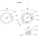
- FIG. 1 shows a conventional coaxial cable 100 and two exemplary cables of the present invention, 200 and 300.
- a coaxial cable is made, generally, of three separate spaces: a metallic inner conductor 110, a metallic outer conductor 130, and a space between them.
- the space between them is usually filled with a low-loss dielectric material 120 (e.g., polytetrafluorethylen, or PTFE) to mechanically support the inner conductor and maintain it with the outer conductor.
- the characteristic impedance of a coaxial cable is fixed by the ratio of diameters of the inner conductor and dielectric material (i.e., inner diameter of the outer conductor) and the permittivity of the space between them.
- the permittivity is fixed because of the solid polymer comprising it.
- a fluid with variable permittivity (or conductivity) at least partially occupies this space, permitting the characteristic impedance of the cable to be adjusted.
- the coaxial cable 200 has the outer portion of the dielectric material removed to create a channel between the dielectric material 120 and the outer conductor 130.
- the created space is separated into four distinct channels 150 by the addition of support lines 140 configured to maintain the space between the outer conductor 130 and the solid dielectric material 120.
- the support lines 140 may be made of any desired material and may be the same or a different material as the solid dielectric material 120.
- the presence of multiple channels permits one or more of the channels to permit flow in one direction (towards the proximal end of the cable) and one or more other channels to permit flow in the opposite direction (towards the distal end of the cable).
- the coaxial cable 300 has a substantial portion of the solid dielectric material 120 removed.
- Such an embodiment may be generated, for example, by stripping away the solid dielectric material 120 down to the surface of inner conductor 110 on each of four sides.
- strips of dielectric material 120 are applied to an inner conductor 110 to create the structure.
- four channels 150 are created.
- the diameter of the outer conductor 130 is substantially reduced.
- the corners provided by the remaining dielectric material 120 provide the support to maintain the position of the outer conductor 130 with respect to the inner conductor 110.
- the overall diameter of the coaxial cable 300 and the device is substantially reduced.
- the present invention provides devices configured to circulate coolant materials for purposes of sinking heat away from the cable itself, and thereby reducing unwanted heating of the medium (e.g., tissue).
- Exemplary coolant fluids include, but are not limited to, one or more of or combinations of, water, glycol, air, inert gasses, carbon dioxide, nitrogen, helium, sulfur hexafluoride, ionic solutions (e.g., sodium chloride with or without potassium and other ions), dextrose in water, Ringer's lactate, organic chemical solutions (e.g., ethylene glycol, diethylene glycol, or propylene glycol), oils (e.g., mineral oils, silicone oils, fluorocarbon oils), liquid metals, freons, halomethanes, liquified propane, other haloalkanes, anhydrous ammonia, sulfur dioxide.
- ionic solutions e.g., sodium chloride with or without potassium and other ions
- dextrose in water Ringer's lactate
- organic chemical solutions e.g., ethylene glycol, diethylene glycol, or propy
- cooling occurs, at least in part, by changing concentrations of coolant, pressure, or volume.
- cooling can be achieved via gas coolants using the Joule-Thompson effect.
- the cooling is provided by a chemical reaction.
- the devices are not limited to a particular type of temperature reducing chemical reaction.
- the temperature reducing chemical reaction is an endothermic reaction.
- the devices are not limited to a particular manner of applying endothermic reactions for purposes of preventing undesired heating.
- first and second chemicals are flowed into the device such that they react to reduce the temperature of the device.
- the device is prepared with the first and second chemicals preloaded in the device.
- the chemicals are separated by a barrier that is removed when desired.
- the barrier is configured to melt upon exposure to a predetermined temperature or temperature range.
- the device initiates the endothermic reaction only upon reaching a heat level that merits cooling.
- multiple different barriers are located throughout the device such that local cooling occurs only at those portions of the device where undesired heating is occurring.
- the barriers used are beads that encompass one of the two chemicals.
- the barriers are walls (e.g., discs in the shape of washers) that melt to combine the two chemicals.
- the barriers are made of wax that is configured to melt at a predetermined temperature.
- the devices are not limited to a particular type, kind or amount of meltable material.
- the meltable material is biocompatible.
- the devices are not limited to a particular type, kind, or amount of first and second chemicals, so long as their mixture results in a temperature reducing chemical reaction.
- the first material includes barium hydroxide octahydrate crystals and the second material is dry ammonium chloride.
- the first material is water and the second material is ammonium chloride.
- the first material is thionyl chloride (SOCl 2 ) and the second material is cobalt(II) sulfate heptahydrate.
- the first material is water and the second material is ammonium nitrate.
- the first material is water and the second material is potassium chloride.
- the first material is ethanoic acid and the second material is sodium carbonate.
- a meltable material is used that, itself, reduces heat by melting an flowing in a manner such that the heat at the outer surface of the device is reduced.
- Figures 2 , 3 , and 7 show device embodiments configured to provide this benefit.
- Figure 2 shows a coaxial cable 400 comprising an outer conductor 401, and an inner conductor 402 that may be extended from the end of the device to deliver energy to a target tissue.
- the solid dielectric material 403 has a channel carved therein 404 that permits fluid flow down the longitudinal length of the coaxial cable 400 to the feed point of the antenna.
- a small transverse channel 405 is provided to allow fluid flow back through a different channel (not shown).
- a fluid reservoir is provided instead of the small transverse channel.
- a fluid reservoir can be created, for example, by removing the dielectric material of the coaxial cable at the location where the cooling channel terminates.
- Figure 3 shows a cut-away view of a coaxial cable 500 with an inner conductor 502 covered by a coating 503 contained within a solid dielectric material 501.
- Two channels 504 are cut through the interior of the dielectric material 501 to permit flow of fluid.
- a small transverse channel 505 is provided to allow fluid flow between the two channels.
- Figures 7A -F show a series of cross-sectional views of cables 750 having an inner conductor 760, a dielectric material 765, a middle coaxial shield 770 (shown as a thin film or foil in 7D and E), and an outer conductor 775.
- Figures 7A -E show the coaxial cable 750 having therein gap areas 780 in between the middle coaxial shield 770 and the outer conductor 775.
- Figure 7F shows the coaxial cable 750 having therein gap areas 780 within the outer conductor 775.
- the gap areas 780 may be used for circulating a coolant material.
- such a coaxial cable may have only one gap area, while in other embodiments, as shown in Figures 7B and 7F , there are two segregated gap areas.
- Such a configuration as shown in Figures 7B and/or 7F permit the input of coolant material through one of the gap areas and the output of the inputted coolant material through the other gap area.
- Such a configuration as shown in Figure 7B permits the input of coolant material through one of the gap areas and the output of the inputted coolant material through the other gap area.
- channels are created by deforming an otherwise circular assembly comprising an inner conductor, dielectric material and middle coaxial shield.
- the channels are created by filling the space between with the coaxial shield and the outer conductor with a material and removing a portion of the material to create a channel.
- the material is a curable material and strips of the material are cured by providing heat along the length of the exterior surface of the outer conductor to create thin, cured strips. The uncured material is then removed, to create channels that are separated by the barriers of cured material.
- the coaxial cable 750 has therein at least one coolant tube 785 positioned within the gap areas 780.
- the present invention is not limited to a particular type or kind of coolant tube 785.
- the composition of the coolant tube 785 is metal, plastic, ceramic, Kevlar, etc.
- the coolant tube 785 is a deformable tube capable of assuming a variety of shapes and configurations (e.g., a Kapton Tube).
- the coolant tube 785 is temperature resistant.
- the coolant tube(s) 785 is positioned such that it does not effect the thickness of the middle coaxial shield 770 or the outer conductor 775.
- the coolant tube(s) 785 is positioned such that it encroaches upon the middle coaxial shield 770 thereby reducing the thickness of the middle coaxial shield 770 at the location of encroachment.
- the coolant tube(s) is positioned such that it encroaches upon the middle coaxial shield 770 and the outer conductor 775 thereby reducing the thickness of the middle coaxial shield 770 and the outer conductor 775 at the location of encroachment.
- the coolant tube(s) is positioned such that it encroaches upon only the outer conductor 775 thereby reducing the thickness of the outer conductor 775 at the location of encroachment.
- a coolant material may be inputted through the coolant tube 785 and outputted through the gap area 780, or the coolant material inputted through the gap area 780 and outputted through the coolant tube 785.
- two coolant tubes 785 are positioned within the gap area 780.
- the coolant material may be inputted through the two coolant tubes 785 and outputted through the gap area 780, or the coolant material inputted through one of the coolant tubes 785 and outputted through the second coolant tube 785, or the coolant material inputted through the gap area 780, and outputted through the coolant tubes 785.
- a plurality of coolant tubes 785 are positioned along the outside of the middle coaxial shield 770.
- any number (e.g., 1, 2, 5, 10) of the coolant tubes 785 may be used to input the coolant material and any number (e.g., 1, 2, 5, 10) of the coolant tubes 785 may be used to output the coolant material.
- half of the coolant tubes 785 are used to input coolant material and half of the coolant tubes 785 are used to output coolant material.
- the gap area 780 may be used to input or output coolant material.
- the coolant tubes 785 are conductive and replace the outer conductor.
- a thin non-conductive sheath 790 encases the device.
- the coaxial cable prevents unwanted heating along the length of the coaxial cable through the positioning of a plurality of coolant tubes along the exterior of the outer conductor.
- Figure 7F provides one such example.
- channels are provided in the outer conductor.
- channels e.g., tubing
- the device may be covered in a sheath (e.g., shrink-wrap material) to securely hold the channels to the outside of the outer conductor.
- sheath e.g., shrink-wrap material
- the device has a handle attached with the device, wherein the handle is configured to, for example, control the passing of coolant into and out of the coolant channels and/or coolant tubes.
- the handle is also connected to coolant and energy delivery systems via one or more cables.
- a single cable connects the energy delivery system (e.g., generator) and coolant system to the handle.
- the cable is attached to the handle at a 90-degree angle or approximately a 90-degree angle.
- the coolant handling system is provided to manage the flow of coolant to the device.
- the coolant handling system is manually controlled.
- the coolant handling system is automatically controlled.
- the temperature of returning coolant is monitored and the temperature is used to determine flow rate of input coolant.
- the energy delivery is also control based on temperature of one or more portions of the device.
- An automated or partially automated system may control a wide variety of operations. For example, in some embodiments, when the device is ready for operation, the automated system primes the cooling system by circulating coolant or another material through the coolant passageways. Once the system is primed, the program enters a normal coolant management protocol.
- one or more temperature sensors that monitor temperature of the coolant, one or more portions of the device, or the surrounding tissue, are used to control coolant flow and/or energy delivery.
- the temperature of the tip or antenna is monitored to make sure it is sufficiently high (e.g., before starting a procedure or before activating the energy delivery mode), while the temperature of the feed line or handle is monitored to maintain a portion of the device at sufficiently low temperature to avoid tissue damage proximal to the treated region.
- the impedance of the device connected to the end of the coaxial cable can also be variable. There are many instances for which this is true, including: a device whose input impedance changes with temperature (e.g., a resonant antenna in a medium of changing permittivity, as in microwave ablation), whose impedance changes over time, changed based on loading further downstream in the network, etc. In these instances, it may be beneficial to change the impedance of the coaxial line feeding these devices.
- a microwave ablation antenna at the end of a coaxial cable may resonate inside the tissue at an initial temperature, T 0 . As the tissue warms, the input impedance and, thus, the resonant frequency of the antenna shift along with the dielectric properties of the tissue.
- This shift causes an impedance mismatch between the feeding coaxial cable and the antenna, which results in reflections from the antenna. This, in turn, results in reduced efficiency in the antenna, less of the desired tissue heating effect and more of the undesirable heating of the feed cable and peripheral tissue proximal to the antenna.
- the present invention provides means for providing this matching by altering the fluid passed through the channels to adjust the characteristic impedance.
- the present invention also provides means for reducing the undesired heating by flowing coolant though the channels.
- kits comprising one or more of a generator, a power distribution system, and an applicator device, along with any one or more accessory agents (e.g., surgical instruments, software for assisting in procedure, processors, temperature monitoring devices, etc.).
- accessory agents e.g., surgical instruments, software for assisting in procedure, processors, temperature monitoring devices, etc.
- the present invention is not limited to any particular accessory agent.
- kits comprising instructions (e.g., ablation instructions, pharmaceutical instructions) along with the systems and devices of the present invention and/or a pharmaceutical agent (e.g., a sedating medication, a topical antiseptic, a topical anesthesia).
- the devices of the present invention may be used in any medical procedure (e.g., percutaneous or surgical) involving delivery of energy (e.g., microwave energy) to a tissue region.
- energy e.g., microwave energy
- the present invention is not limited to a particular type or kind of tissue region (e.g., brain, liver, heart, blood vessels, foot, lung, bone, etc.).
- the systems of the present invention find use in ablating tumor regions.
- the applicator device is inserted into, for example, a subject such that the distal end of the distal coaxial outer shield is positioned in the vicinity of the desired tissue region.
- the generator is used to provide a desired amount of microwave energy to the power distribution system at a characteristic impedance level, which in turn provides the energy at a characteristic impedance level to the applicator device.
- the distal coaxial center conductor is extended from the distal coaxial outer shield in a manner retaining the characteristic impedance level.
- a desired amount of microwave energy is delivered to the desired tissue region (e.g., tumor) generating an electric field of sufficient strength to ablate the desired tissue region. Due to the characteristic impedance level maintained throughout the transmission lines of the applicator device, the overall temperature of the transmission lines is greatly reduced, resulting in a reduced chance for undesired tissue overheating.
- the devices may be used in methods involving the simultaneous use of multiple (e.g., two or more) applicator devices for the treatment of a tissue.
- the devices may also be used in methods wherein the simultaneous use of multiple antennas are phased to achieve constructive and destructive interference (e.g., for purposes of selectively destroying and sparing portions of a tissue region).
- the present invention further provides software for regulating the amount of microwave energy provided to a tissue region through monitoring of the temperature of the tissue region (e.g., through a feedback system).
- the software is configured to interact with the systems for microwave therapy of the present invention such that it is able to raise or lower (e.g., tune) the amount of energy delivered to a tissue region.
- the type of tissue being treated e.g., liver
- the software is inputted into the software for purposes of allowing the software to regulate (e.g., tune) the delivery of microwave energy to the tissue region based upon pre-calibrated methods for that particular type of tissue region.
- the software provides a chart or diagram based upon a particular type of tissue region displaying characteristics useful to a user of the system.
- the software provides energy delivering algorithms for purposes of, for example, slowly ramping power to avoid tissue cracking due to rapid out-gassing created by high temperatures.
- the software allows a user to choose power, duration of treatment, different treatment algorithms for different tissue types, simultaneous application of power to the antennas in multiple antenna mode, switched power delivery between antennas, coherent and incoherent phasing, etc.
- the software is configured for imaging equipment (e.g., computerized tomography (CT), magnetic resonance imaging (MRI), ultrasound).
- imaging equipment software allows a user to make predictions based upon known thermodynamic and electrical properties of tissue and location of the antenna(s).
- the imaging software allows the generation of a three-dimensional map of the location of a tissue region (e.g., tumor, arrhythmia), location of the antenna(s), and to generate a predicted map of the ablation zone.
Description
- The present invention relates to systems and devices for delivering energy to tissue for a wide variety of applications, including medical procedures (e.g., tissue ablation, resection, cautery, vascular thrombosis, treatment of cardiac arrhythmias and dysrhythmias, electrosurgery, tissue harvest, etc.). In particular, the present invention relates to systems and devices for the delivery of energy with heat transfer ability. In some embodiments, the systems and devices also have variable characteristic impedance as a result of the use of heat transfer materials.
- Ablation is an important therapeutic strategy for treating certain tissues such as benign and malignant tumors, cardiac arrhythmias, cardiac dysrhythmias and tachycardia. Most approved ablation systems utilize radio frequency (RF) energy as the ablating energy source. Accordingly, a variety of RF based catheters and power supplies are currently available to physicians. However, RF energy has several limitations, including the rapid dissipation of energy in surface tissues resulting in shallow "burns" and failure to access deeper tumor or arrhythmic tissues. Another limitation of RF ablation systems is the tendency of eschar and clot formation to form on the energy emitting electrodes which limits the further deposition of electrical energy.
- Microwave energy is an effective energy source for heating biological tissues and is used in such applications as, for example, cancer treatment and preheating of blood prior to infusions. Accordingly, in view of the drawbacks of the traditional ablation techniques, there has recently been a great deal of interest in using microwave energy as an ablation energy source. The advantage of microwave energy over RF is the deeper penetration into tissue, insensitivity to charring, lack of necessity for grounding, more reliable energy deposition, faster tissue heating, and the capability to produce much larger thermal lesions than RF, which greatly simplifies the actual ablation procedures. Accordingly, there are a number of devices under development that utilize electromagnetic energy in the microwave frequency range as the ablation energy source (see, e.g.,
U.S. Patent Nos. 4,641,649 ,5,246,438 ,5,405,346 ,5,314,466 ,5,800,494 ,5,957,969 ,6,471,696 ,6,878,147 , and6,962,586 ;). - Unfortunately, current devices configured to deliver microwave energy have drawbacks. For example, current devices produce relatively small lesions because of practical limits in power and treatment time. Current devices have power limitations in that the power carrying capacity of the feedlines is small. Larger diameter feedlines are undesirable, however, because they are less easily inserted percutaneously and may increase procedural complication rates. In addition, heating of the feedline at high powers can lead to burns around the area of insertion for the device.
- Improved systems and devices for delivering energy to a tissue region are needed. In addition, improved systems and devices capable of delivering microwave energy without corresponding microwave energy loss are needed. In addition, systems and devices capable of percutaneous delivery of microwave energy to a subject's tissue without undesired tissue burning are needed. Furthermore, systems for delivery of desired amounts of microwave energy without requiring physically large invasive components are needed.
-
US2004133254 describes that each of various modifications of an integrated-structure inflatable balloon catheter design includes a longitudinal structure having a sharply-pointed insertion needle at a distal end of the longitudinal structure and an inflatable balloon situated intermediate a proximate end and the distal end of the longitudinal structure which is attached to said longitudinal structure. With the inflatable balloon in a deflated state, the insertion needle may be used to puncture the patient's skin and underlying sub-cutaneous tissue and place the deflated balloon in proximity to the diseased sub-cutaneous tissue. The balloon is then inflated to press against and thereby spatially deform the diseased sub-cutaneous tissue, after which the deformed diseased sub-cutaneous tissue may be therapeutically heated. This heating may be sufficient to cause the creation of a permanent cavity in the deformed diseased sub-cutaneous tissue which persists after the catheter is withdrawn. This permits any selected one of various therapeutic substances to be introduced into this a permanent cavity. One modification employs a balloon having a selected non-uniform, odd pattern shape which, when inflated, cooperates with the shape of the diseased sub-cutaneous tissue. This one modification also may be beneficially used in prostate-treating balloon catheters, which do not have a sharply-pointed insertion needle at the distal end thereof. -
US 2005/015081 describes devices and methods for cooling microwave antennas. The cooling systems can be used with various types of microwave antennas. One variation generally comprises a handle portion with an elongate outer jacket extending from the handle portion. A microwave antenna is positioned within the handle and outer jacket such that cooling fluid pumped into the handle comes into contact directly along a portion of the length, or a majority of the length, or the entire length of the antenna to allow for direct convective cooling. Other variations include cooling sheaths which form defined cooling channels around a portion of the antenna. Yet another variation includes passively-cooled systems which utilize expandable balloons to urge tissue away from the surface of the microwave antenna as well as cooling sheaths which are cooled through endothermic chemical reactions. Furthermore, the microwave antennas themselves can have cooling lumens integrated directly therethrough. -
WO 2006/002943 describes a radiation applicator for applying electromagnetic radiation to tissue, comprising: an axial central conductor adapted to be coupled to a source of electromagnetic radiation and defining an axis; an elongate dielectric member, the dielectric member surrounding at least part of said central conductor along an axial length thereof; a metal ferrule, the ferrule being attached to the dielectric member and surrounding a portion of the central conductor and extending parallel thereto along a length thereof. The ferrule and the dielectric member have respective elongate cooperating surfaces and wherein the ferrule and the dielectric member are fixed to each other with said cooperating surfaces in close abutment, thereby providing a rigid structure. -
US 2005/245919 describes an improved antenna for microwave ablation uses a triaxial design which reduces reflected energy allowing higher power ablation and/or a smaller diameter feeder line to the antenna. - The invention is defined in the accompanying claims.
Embodiments, aspects and examples disclosed herein, but not falling under the scope of claim 1, do not form part of the invention. This applies in particular to the methods disclosed herein. Embodiments of this invention can provide devices for delivering energy to tissue for a wide variety of applications, including medical procedures (e.g., tissue ablation, resection, cautery, vascular thrombosis, intraluminal ablation of a hollow viscus, cardiac ablation for treatment of arrhythmias, electrosurgery, tissue harvest, cosmetic surgery, intraocular use, etc.). In particular, embodiments of this invention can provide devices for the delivery of energy with heat transfer ability. In some embodiments, the device may also have variable characteristic impedance as a result of the use of heat transfer materials. - Embodiments of this invention can provide a variety of heat transfer mechanisms. In some embodiments, heat transfer is provided in small diameter devices. The outer diameter of the device is equivalent to, or smaller than, a 16-gauge needle (e.g., equal or smaller than a 17-gauge needle, a 20-gauge needle, etc.). Embodiments of the present invention can provide configurations of the devices that balance energy delivery, heat management, and size. Existing devices, to provide appropriate energy delivery and heat management, are large in diameter, making them undesirable or unsuitable for many applications. In some embodiments, the present invention provides small diameter devices with optimized energy and heating characteristics by providing a cooling material within a coaxial or triaxial cable. For example, in some embodiments, the cooling material is provided material separating an inner and outer conductor of a coaxial cable (or central conductor of a triaxial cable), between dielectric material and outer conductor of a coaxial cable (or central conductor of a triaxial cable), between the outer two conductors of a triaxial cable. Examples of some such embodiments are described in more detail below. In some embodiments, space is created for the cooling material, while maintaining the small diameter, by one or more of: removing all of or a portion of a dielectric material; using thin conductive coatings as conductors; and using deformable tubing to carry cooling material within a coaxial or triaxial cable. In some embodiments, the coolant material is directly flowed through a created space. In other embodiments one or more tubes is provided in the space and coolant is flowed in the tube(s) and/or in the tube(s) and the space outside of the tube(s). In some embodiments, cooling material is provided in one direction (e.g., down the device or up the device) through a tube and the opposition direction outside of a tube. The tubes may be rigid or deformable. For example, in some embodiments, an inner conductor is contained within a minimal amount of dielectric material, the dielectric material is coated with a thin conductive film or is covered in a conductive foil so as to provide a coaxial structure, one or more deformable tubes are assembled outside of the film or foil, and a conductive outer member, having a small outer diameter, is placed of the assembly to provide a triaxial device having a small diameter combined with suitable energy delivery and heat management capabilities. By providing sufficient cooling, in a small diameter device, high amounts of power can be sent through the device without overheating, permitting, for example, tissue ablation that would otherwise only be achievable with larger diameter devices. In some embodiments, the tube for conducting coolant is replaced by a fiber whose wicking action enables the flow of coolant in a space-efficient manner.
- In some embodiments, the cooling material is provided along only a portion of an energy delivery device. For example, in some embodiments, an energy delivery device comprises a distal tip, an antenna connected to the tip and configured to deliver energy, a feed line that connects to the antenna on the proximal end of the antenna, and a handle at the proximal end of the feed line. In some embodiments, only the handle is contacted with the cooling material. In some embodiments, only the feed line, or portion thereof (e.g., 90% of the length thereof or less, 80%, 70%, 60%, 50%, 40%, etc.), is contacted with the cooling material. In some embodiments, both the handle and the feed line, or a portion thereof, is contacted with the cooling material. In some embodiments, the antenna and/or tip are not contacted with the cooling material (e.g., the cooling material is only flowed to the feed line, and does not travel a sufficient length of the device to reach the antenna).
- In some embodiments, the device may include coaxial transmission lines that allow cooling by circulation of a coolant material through the coaxial transmission line (e.g., circulation of a coolant material through coolant tubes positioned within the coaxial cable) (e.g., through flowing of a coolant material through the dielectric of the coaxial component). In some embodiments, the devices are configured to minimize the diameter of the device, while permitting the passage of the coolant. This is accomplished, in some embodiments, by positioning of deformable coolant tubes (e.g., Kapton tubes) within the coaxial cable. In such embodiments, a triaxial cable comprises a dielectric material positioned between an inner conductor and a middle coaxial shield, and deformable coolant tubes positioned between the middle coaxial shield and an outer conductor. The devices are not limited to a particular middle coaxial shield. In some embodiments, the middle coaxial shield is a thin (e.g., 0.25 mm, 0.5 mm, 1.0 mm, 1.2 mm, 1.4 mm, 1.6 mm, 2.5 mm, etc.) flexible metal (e.g., copper). The devices are not limited to particular coolant tubes. In some embodiments, the coolant tubes are deformable such that upon positioning within a coaxial tube, the tubes will deform but retain an ability to circulate a coolant material (e.g., nitrogen, carbon dioxide, water). In some embodiments, the coolant tubes are Kapton tubes or similar polymer films. As such, the devices providing coolant tubes provide not only an ability to control the temperature of the device (e.g., through circulation of coolant material through the coolant tubes), but also provide an ability to retain its small size (e.g., due to the use of deformable coolant tubes that do not increase the overall diameter of the device).
- In some embodiments, the devices are configured to minimize the diameter of the device, while permitting the passage of the coolant, by replacing strips of a solid dielectric material with channels through which a coolant is transferred. In some embodiments, the channels are generated by stripping the dielectric material along the length of the coaxial cable from one or more (e.g., two, three, four) zones. With the removed portions of the dielectric material creating channels for transfer of the coolant, the stripped component fits within a smaller outer conductor than it did prior to removal of the dielectric material (see
Figure 1 , element 300). This provides for smaller devices with all of the advantages derived therefrom. In some embodiments where multiple channels are employed, coolant transfer may be in alternative directions through one or more of the channels. An advantage of the devices is that the diameter of the coaxial cable does not need to be increased to accommodate coolant. This permits the use of cooled devices that are minimally invasive and permits access to regions of a body that are otherwise inaccessible or accessible only with undesired risk. The use of coolant also permits greater energy delivery and/or energy deliver for prolonged periods of time. - The devices of the present invention may further allow for adjustment of the characteristic impedance of the coaxial transmission line. In particular, the dielectric properties of the coolant (or of a non-coolant material that is passed through the coolant tubes and/or channel(s)) may be adjusted to alter the bulk complex permittivity of the dielectric medium separating the outer and inner conductors. In some embodiments, changes in the characteristic impedance are made during a procedure to, for example, optimize energy delivery, tissue effects, temperature, or other desired properties of the device or application. In other embodiments, a flow material is selected prior to a procedure based on the desired parameters and maintained throughout the entire procedure. Thus, the present invention can provides devices that allow an antenna radiating in a changing dielectric environment to be adjusted to resonate in the changing environment to, for example, allow adaptive tuning of the antenna to ensure peak efficiency of operation. As desired, the fluid flow also allows heat transfer to and from the coaxial cable. The present invention is not limited by the means by which the characteristic impedance is altered. In some embodiments, the coolant tubes and/or channels or hollowed out areas contain a vacuum or partial vacuum. In some embodiments, impedance is varied by filling the vacuum with a material (e.g., any material that provides the desired result). Adjustments may be made at one or more time points or continuously.
- The present invention is not limited by the method by which material is flowed through the dielectric. In some embodiments, the channel is cut through only a portion of the dielectric material so that the flowed material is in contact with the outer conductor and the remaining dielectric material. In some embodiments, the channels are linear along the length of the coaxial cable. In some embodiments, the channels are non-linear. In some embodiments, the channels run parallel to one another. In other embodiments, the channels are not parallel. In some embodiments, the channels cross one another. In some embodiments, the channels remove over 50% (e.g., 60%, 70%, 80%, etc.) of the solid dielectric material. The present invention is not limited by the nature of the material that is flowed through the dielectric material. In some embodiments, the material is selected to maximize the ability to control the characteristic impedance of the device, to maximize heat transfer to or from the coaxial cable, or to optimize a combination of control of the characteristic impedance and heat transfer. In some embodiments, the material that is flowed through the dielectric material is a liquid. In some embodiments, the material is a gas. In some embodiments, the material is a combination of liquid or gas. In some embodiments, the liquid and/or gas is provided at the respective critical point temperature. The present invention is not limited to the use of liquids or gasses. In some embodiments, the material is a slurry, a gel, or the like. In some embodiments, a coolant fluid is used. Any coolant fluid now known or later developed may be used. Exemplary coolant fluids include, but are not limited to, one or more of or combinations of, water, glycol, air, inert gasses, carbon dioxide, nitrogen, helium, sulfur hexafluoride, organic chemical solutions (e.g., ethylene glycol, diethylene glycol, or propylene glycol), oils (e.g., mineral oils, silicone oils, fluorocarbon oils), liquid metals, freons, halomethanes, liquified propane, other haloalkanes, anhydrous ammonia, sulfur dioxide.
- In some embodiments, the devices of the present invention are configured to permit control over the parameters of fluid infusion through the device. In some embodiments, the device is manually adjusted by the user (e.g., a treating physician or technician) as desired. In some embodiments, the adjustments are automated. In some embodiments, the devices are configured with or used with sensors that provide information to the user or the automated systems (e.g., comprising processors and/or software configured for receiving the information and adjusting fluid infusion or other device parameters accordingly). Parameters that may be regulated include, but are not limited to, speed of infusion of the fluid, concentration of ions or other components that affect the properties of the fluid (e.g., dielectric properties, heat transfer properties, flow rate, etc.), temperature of the fluid, type of fluid, mixture ratios (e.g., mixtures of gas/fluid for precise tuning or cooling). Thus, the present invention can provide devices employing a feed-back loop that can change one or more desired parameters to tune the device (e.g., antenna) more accurately, or speed up the infusion of the fluid if the device, portions of the device, or tissue of the subject reaches an undesired temperature (or a temperature for an undesired period of time).
- The present invention is not limited by the type of device or the uses employed. Indeed, the devices may be configured in any desired manner. Likewise, the devices may be used in any application where energy is to be delivered. Such uses include any and all medical, veterinary, and research applications. However, the devices of the present invention may be used in agricultural settings, manufacturing settings, mechanical settings, or any other application where energy is to be delivered.
- The device is not limited to delivering a particular type of energy. In some embodiments, the type of energy delivered by the device is microwave energy, in other embodiments the type of energy is radio frequency energy while in other embodiments it is multiple types of energy. In some embodiments, the device is combined with other medical devices such as cutting devices. The cutting devices may also employ energy, such as laser or radiofrequency energy.
- In some embodiments, the device is configured for percutaneous, laparoscopic, intravascular, intracardiac, or surgical delivery of energy. In some embodiments, the device is configured for delivery of energy to a target tissue or region. The present invention is not limited by the nature of the target tissue or region. Uses include, but are not limited to, treatment of heart arrhythmia, tumor ablation (benign and malignant), control of bleeding during surgery, after trauma, for any other control of bleeding, removal of soft tissue, tissue resection and harvest, treatment of varicose veins, intraluminal tissue ablation (e.g., to treat esophageal pathologies such as Barrett's Esophagus and esophageal adenocarcinoma), treatment of bony tumors, normal bone, and benign bony conditions, intraocular uses, uses in cosmetic surgery, treatment of pathologies of the central nervous system including brain tumors and electrical disturbances, and cauterization of blood vessels or tissue for any purposes. In some embodiments, the surgical application comprises ablation therapy (e.g., to achieve coagulation necrosis). In some embodiments, the surgical application comprises tumor ablation to target, for example, metastatic tumors. In some embodiments, the device is configured for movement and positioning, with minimal damage to the tissue or organism, at any desired location, including but not limited to, the brain, neck, chest, abdomen, and pelvis. In some embodiments, the device is configured for guided delivery, for example, by computerized tomography (CT), ultrasound, magnetic resonance imaging (MRI), fluoroscopy, and the like.
- The device is not limited to a particular type of coaxial transmission line. In some embodiments, the coaxial transmission line has an inner conductor, a dielectric element, and an outer shield (e.g., outer conductor). In some embodiments, transmission line has a triaxial configuration and has therein a middle coaxial shield (which can be, for example, a metallic foil, film, mesh, or spiral conductor) positioned between the dielectric element and the outer conductor. In some embodiments, the outer shield is a 20-gauge needle or a component of similar diameter to a 20-gauge needle. Preferably, the outer shield is not larger than a 16-gauge needle (e.g., no larger than an 18-gauge needle). In some embodiments, the outer shield is a 17-gauge needle. However, in some embodiments, larger devices are used, as desired. For example, in some embodiments, a 12-gauge diameter is used. The present invention is not limited by the size of the outer shield component. In some embodiments, the center conductor is configured to extend beyond the outer shield for purposes of delivering energy to a desired location. In preferred embodiments, some or all of the feedline characteristic impedance is optimized for minimum power dissipation, irrespective of the type of antenna that terminates at its distal end.
- In some embodiments, the device of the present invention provide multiple feedlines and/or multiple antennas to affect one or more locations in a subject. Such application include, but are not limited to, treating large tumor masses or tumor masses having irregular shapes, where one or more of the components capable of delivered energy is inserted to a first position of a tumor and one or more of the components is inserted to a second (third, etc.) position of a tumor. In some embodiments, a first component capable of delivering energy is a first size and a second component capable of delivery energy is a second size. Such an embodiment, adds to the choices a user has in delivering the desired amount of energy for a particular application. For example, in embodiments where the size of the injury created by insertion of the device into a subject is less relevant and the tissue zone to be ablated is larger, the user may select a larger needle to deliver more energy. In contrast, where the injury associated with the insertion is to be minimized, two or more smaller needles may be used (e.g., bundled together or separately). In preferred embodiments, some or all of the feedline characteristic impedance is optimized for minimum power dissipation, irrespective of the type of antenna that terminates it distal end. In some embodiments, the device has therein multiple antenna arrays of the same or different shapes (e.g., umbrella-shaped probes, trident shaped, etc.).
- In some embodiments, one or more components of the device of the present invention may contain a coating (e.g., Teflon or any other insulator) to help reduce heating or to impart other desired properties to the component. For example, in some embodiments of the present invention, the antennae, and or the feedline, are coated with a biocompatible material that reduces tissue sticking to the device (e.g., Teflon). Coating prevents undesired tissue sticking during use of the device, and thereby permits the antennae to be used without additional cooling measures (e.g., the antennae may be used without having coolant directly engaging the antennae).
- In some embodiments, the device further comprises a tuning element for adjusting the amount of energy delivered to the tissue region. In some embodiments, the tuning element is manually adjusted by a user of the device. In some embodiments, the device is pretuned to the desired tissue and is fixed throughout the procedure. In some embodiments, the tuning element is automatically adjusted and controlled by a processor of the present invention, in some embodiments, the processor adjusts the energy delivery over time to provide constant energy throughout a procedure, taking into account any number of desired factors including, but not limited to, heat, nature and/or location of target tissue, size of lesion desired, length of treatment time, proximity to sensitive organ areas, and the like. In some embodiments, the system comprises a sensor that provides feedback to the user or to a processor that monitors the function of the device continuously or at time points. The sensor may record and/or report back any number of properties, including, but not limited to, heat at one or more positions of a component of the system, heat at the tissue, property of the tissue, and the like. The sensor may be in the form of an imaging device such as CT, ultrasound, magnetic resonance imaging, or any other imaging device. In some embodiments, particularly for research application, the system records and stores the information for use in future optimization of the system generally and/or for optimization of energy delivery under particular conditions (e.g., patient type, tissue type, size and shape of target region, location of target region, etc.).
- The device and a power distributor can be used for ablation therapy, for percutaneous delivery of energy to a tissue region. In some embodiments, the power distributor includes a power splitter configured to deliver energy to multiple antennas (e.g., the same energy power to each antenna, different energy powers to different antennas). In some embodiments, the power splitter is able to receive power from one or more power distributors. A method for treating a tissue region can comprise providing a target tissue or organism and a device of the present invention for delivery of energy to a tissue region. The method can further comprise the positioning of the device in the vicinity of the tissue region, and the percutaneous delivering of an amount of energy with the device to the tissue region. The delivering of the energy results in, for example, the ablation of the tissue region and/or thrombosis of a blood vessel, and/or electroporation of a tissue region. The tissue region may be a tumor. The tissue region may comprise one or more of the heart, liver, genitalia, stomach, lung, large intestine, small intestine, brain, neck, bone, kidney, muscle, tendon, blood vessel, prostate, bladder, and spinal cord.
- The device of the present invention may be used in conjunction with other systems and devices. For example, the device of the present invention may be used with other ablation devices, other medical devices, diagnostic methods and reagents, imaging methods and reagents, and therapeutic methods and agents. Use may be concurrent or may occur before or after another intervention. The use of the device in conjunction with any other medical interventions is contemplated.
-
-
Figure 1 shows a transverse cross-section schematic of a standard coaxial cable (100) and two embodiments of the present invention (200, 300). -
Figure 2 shows an embodiment of the present invention where longitudinal fluid channels run the length of the cable to the feed point of the antenna, wherein a small transverse channel is inserted to allow fluid flow back through a different channel. -
Figure 3 shows an embodiment of a device of the present invention to flow fluid to and from the cable. -
Figure 4 shows a graph of characteristic impedance of a simulated line versus relative permittivity of the fluid layer. -
Figure 5 shows a graph of characteristic impedance versus conductivity of the fluid layer. -
Figure 6 shows graphs of reflection coefficient versus frequency for a triaxial antenna with standard coaxial cable (top) and the same antenna fed by a water-filled cable (bottom). -
Figures 7A -F show a series of cross-sectional views of cables having an inner conductor, a dielectric material, a middle coaxial shield, and an outer conductor, in some embodiments of the present invention. - The present invention relates to systems and devices for delivering energy to tissue for a wide variety of applications, including medical procedures (e.g., tissue ablation, treatment of arrhythmias, cautery, vascular thrombosis, electrosurgery, tissue harvest, etc.). In particular, the present invention relates to systems and devices for the delivery of energy with heat transfer ability. In some embodiments, the systems and devices also have variable characteristic impedance as a result of the use of heat transfer materials. In certain embodiments, methods are provided for treating a tissue region (e.g., a tumor) through application of energy with the systems and devices of the present invention.
- In preferred embodiments, the systems, devices, and methods of the present invention employ microwave energy. The use of microwave energy in the ablation of tissue has numerous advantages. For example, microwaves have a broad field of power density (e.g., approximately 2 cm surrounding an antenna depending on the wavelength of the applied energy) with a correspondingly large zone of active heating, thereby allowing uniform tissue ablation both within a targeted zone and in perivascular regions (see, e.g., International Publication No.
WO 2006/004585 ). In addition, microwave energy has the ability to ablate large or multiple zones of tissue using multiple probes with more rapid tissue heating. Microwave energy has an ability to penetrate tissue to create deep lesions with less surface heating. Energy delivery times are shorter than with radiofrequency energy and probes can heat tissue sufficiently to create an even and symmetrical lesion of predictable and controllable depth. Microwave energy is generally safe when used near vessels. Also, microwaves do not rely on electrical conduction; they can radiate through tissue, fluid/blood, as well as air. Therefore, they can be used in tissue, lumens lungs, and intravascularly. - The illustrated embodiments provided below describe the systems and devices of the present invention in terms of medical applications (e.g., ablation of tissue through delivery of microwave energy). However, it should be appreciated that the systems and devices of the present invention are not limited to a medical applications. In addition, the illustrated embodiments describe the systems and devices of the present invention in terms of medical devices configured for tissue ablation. It should be appreciated that the systems and devices of the present invention are not limited to medical devices configured for tissue ablation. The illustrated embodiments describe the systems and devices of the present invention in terms of microwave energy. It should be appreciated that the systems and devices of the present invention are not limited to a particular type of energy (e.g., radiofrequency energy).
- The systems and devices of the present invention provide numerous advantages over the currently available systems and devices. For example, a major drawback with currently available medical devices that utilize microwave energy is the undesired dissipation of the energy through transmission lines onto a subject's tissue resulting in undesired burning. Such microwave energy loss results from limitations within the design of currently available medical devices. In particular, medical devices utilizing microwave energy transmit energy through coaxial cables having therein a dielectric material (e.g., polytetrafluorethylen, or PTFE) surrounding an inner conductor. Dielectric materials such as PTFE have a finite conductivity, which result in the undesired heating of transmission lines. This is particularly true when one supplies the necessary amounts of energy for a sufficient period of time to enable tissue ablation. The present invention provides systems, devices, and methods that overcome this limitation. In particular, the present invention provides means for flowing coolant through the device to manage heating. As described in more detail below, the overall temperature of the transmission lines within the medical devices of the present invention are reduced, and therefore, reduces undesired tissue heating. Thus, in some embodiments, the systems and devices of the present invention are provided with a coolant that runs through at least a portion of the dielectric material, which may be partly or completely made of mesh or other porous construction. This is in contrast, for example, to coolant systems that are provided in an external cooling jacket that surrounds a coaxial cable, antenna, or device.
- In addition, in some embodiments, by providing improved coaxial transmission lines configured for coolant material circulation, by using one or more space-saving techniques, , the coaxial transmission line may be designed such that it can fit within very small needles (e.g., 16-20 gauge needles or smaller). Typically, medical devices configured to delivery microwave energy are designed to fit within large needles due to bulky dielectric materials. Microwave ablation has not been extensively applied clinically due to the large probe size (14 gauge) and relatively small zone of necrosis (1.6 cm in diameter) (Seki T et al., Cancer 74:817 (1994)) that is created by the only commercial device (Microtaze, Nippon Shoji, Osaka, Japan. 2.450 MHz, 1.6 mm diameter probe, 70 W for 60 seconds). Other devices use a cooling external water jacket that also increases probe size and can increase tissue damage. These large probe sizes increase the risk of complications when used in the chest and abdomen. In some embodiments of the present invention, the maximum outer diameter of the portion of the device that enters a subject is 16-18 gauge or less (20 gauge or less).
- Moreover, by providing improved coaxial transmission lines designed to prevent undesired heating, the coaxial cables may be heated to temperatures at or above (e.g., 10%, 20%, 50%, etc. above) the manufacturer's rated temperature failure points.
- The energy delivery systems of the present invention contemplate the use of any type of device configured to deliver (e.g., emit) energy (e.g., ablation device, surgical device, etc.) (see, e.g.,
U.S. Patent Nos. 7,101,369 ,7,033,352 ,6,893,436 ,6,878,147 ,6,823,218 ,6,817,999 ,6,635,055 ,6,471,696 ,6,383,182 ,6,312,427 ,6,287,302 ,6,277,113 ,6,251,128 ,6,245,062 ,6,026,331 ,6,016,811 ,5,810,803 ,5,800,494 ,5,788,692 ,5,405,346 ,4,494,539 ,U.S. Patent Application Serial Nos. 11/514,628 ,11/502,783 11/452,637 11/440,331 11,237,430 11/237,136 11/236,985 10/980,699 10/961,994 10/961,761 10/834,802 10/370,179 09/847,181 U.S. Provisional Patent Nos. 60/785,690 ,60/785,467 60/785,466 2,406,521 2,388,039 1395190 ; and International Patent Application Nos.WO 06/008481 WO 06/002943 WO 05/034783 WO 04/112628 WO 04/033039 WO 04/026122 WO 03/088858 WO 03/039385 WO 95/04385 - In some embodiments, the systems utilize energy delivery devices having therein antennae configured to emit energy (e.g., microwave energy, radiofrequency energy). The systems are not limited to particular types or designs of antennae (e.g., ablation device, surgical device, etc.).. In some embodiments, the systems utilize energy delivery devices having linearly shaped antennae (see, e.g.,
U.S. Patent Nos. 6,878,147 ,4,494,539 ,U.S. Patent Application Serial Nos. 10/961,994 ,10/961,761 U.S. Provisional Patent Nos. 60/785,690 ,60/785,467 60/785,466 WO 03/039385 U.S. Patent Nos. 6,251,128 ,6,016,811 , and5,800,494 ,U.S. Patent Application Serial No. 09/847,181 , and International Patent Publication No.WO 03/088858 - In some embodiments, the antennae have horn reflection components (see, e.g.,
U.S. Patent Nos. 6,527,768 ,6,287,302 ). - In some embodiments, the antenna has a directional reflection shield (see, e.g.,
U.S. Patent No. 6,312,427 ). In some embodiments, the antenna has therein a securing component so as to secure the energy delivery device within a particular tissue region (see, e.g.,U.S. Patent Nos. 6,364,876 , and5,741,249 ). - The energy emitting devices of embodiments of the present invention may be manufactured in a variety of ways. An exemplary manufacturing method for a triaxial device of some embodiments of the invention is provided below. In some embodiments, an interior portion comprising the inner conductor is made first. In some such embodiments, an inner conductor is provided and is coated with a dielectric material and a thin metal coating. In some embodiments, no dielectric material is used (e.g., air or other material occupies the space between the inner conductor and the thin metal coating). In some embodiments, the thin metal coating is a metal foil that is wrapped around the inner conductor and/or dielectric material. In some embodiments, the dielectric material and metal coating are provided by use of a metal-coated deformable tube (e.g., Kapton tube) that is inserted over the inner conductor. One or more of the components may be glued to one another. In some embodiments, this assembly is manufactured in long lengths that are cut to size. In other embodiments, the assembly is manufactured at final length. In some embodiments, coolant tubes (e.g., deformable tubes) are then attached to the outer surface of the conductive metal or film. The coolant tubes may run any desired length along the device. This assembly may also be manufactured in long lengths and cut to size. An outer conductor is then placed over the assembly, encompassing the inner conductor, the metal film or foil, and the coolant tubes. In some embodiments, the inner conductor extends distally beyond the length of the other components. This portion of the inner conductor may be covered in a non-conductive material, so as to provide an antenna for energy delivery. In some embodiments, a non-conducive tip is positioned on the distal end of the device. The tip may be fashioned with a sharp point to assist in penetration of and navigation through tissue. In some embodiments, a handle is positioned on the proximal end of the device. In some embodiments, the handle is provided as two or more pieces that snap or are fused together. The handle pieces contain channels to accommodate an electric connection between the triaxial cable a power delivery system and between a coolant source and coolant tubes or channels in the energy delivery device. In some embodiments, connections are sealed. In some embodiments, one or more of the tip, antenna portion, feed line portion (comprising the triaxial cable), and handle are coated with a material that provides one or more of: biocompatibility and non-stick surface. Non-conductive segments may be attached to metal coated segments via any desired mechanism. In some embodiments, connections are designed to "snap fit" into a secure engagement, for example, at the end of the triaxial cable. In some embodiments, glue or other adhesives are used. In some embodiments, insert molding/thermoforming is used. For example, holes may be drilled in the end of the outer conductor of the triaxial cable and insert molding/thermoforming is carried out by melting the non-conductive material so that it forms into the holes.
- The present invention is not limited to a particular coaxial transmission line cross-sectional shape. Indeed, in some embodiments, the shape of the coaxial transmission line and/or the dielectric element is selected and/or adjustable to fit a particular need. For example, potential cross-sectional shapes for the transmission lines or portions thereof (e.g., at the circumference of the dielectric material, the middle coaxial shield, the outer conductor, etc.). include, but are not limited to, circular, oval, square, rectangular, oblong, diagonal, triangular, or various irregular shapes. In some embodiments, the shapes are designed so as to accommodate and/or include flow channels within the transmission line. In some embodiments, the transmission line is shaped to assume a particular region of interest (e.g., a body orifice). Certain preferred embodiments of the present invention are described below. The present invention is not limited to these embodiments.
-
Figure 1 shows a conventionalcoaxial cable 100 and two exemplary cables of the present invention, 200 and 300. A coaxial cable is made, generally, of three separate spaces: a metallicinner conductor 110, a metallicouter conductor 130, and a space between them. The space between them is usually filled with a low-loss dielectric material 120 (e.g., polytetrafluorethylen, or PTFE) to mechanically support the inner conductor and maintain it with the outer conductor. The characteristic impedance of a coaxial cable is fixed by the ratio of diameters of the inner conductor and dielectric material (i.e., inner diameter of the outer conductor) and the permittivity of the space between them. Usually, the permittivity is fixed because of the solid polymer comprising it. However, in embodiments of the present invention, a fluid with variable permittivity (or conductivity) at least partially occupies this space, permitting the characteristic impedance of the cable to be adjusted. - In one embodiment of the present invention, the
coaxial cable 200 has the outer portion of the dielectric material removed to create a channel between thedielectric material 120 and theouter conductor 130. In the embodiments shown, the created space is separated into fourdistinct channels 150 by the addition ofsupport lines 140 configured to maintain the space between theouter conductor 130 and the soliddielectric material 120. The support lines 140 may be made of any desired material and may be the same or a different material as the soliddielectric material 120. The presence of multiple channels permits one or more of the channels to permit flow in one direction (towards the proximal end of the cable) and one or more other channels to permit flow in the opposite direction (towards the distal end of the cable). - In another embodiment, the
coaxial cable 300 has a substantial portion of the soliddielectric material 120 removed. Such an embodiment may be generated, for example, by stripping away the soliddielectric material 120 down to the surface ofinner conductor 110 on each of four sides. In another embodiment, strips ofdielectric material 120 are applied to aninner conductor 110 to create the structure. In this embodiment, fourchannels 150 are created. By removing a substantial amount of thedielectric material 120, the diameter of theouter conductor 130 is substantially reduced. The corners provided by the remainingdielectric material 120 provide the support to maintain the position of theouter conductor 130 with respect to theinner conductor 110. In this embodiment, the overall diameter of thecoaxial cable 300 and the device is substantially reduced. - Large electric fields caused by large powers and small cable diameters can generate heat within the dielectric material that lead to unwanted heating of the medium (e.g., tissue) into which the cable is immersed. Thus, it is desirable to be able to counteract this effect and sink heat out of the cable to reduce any unwanted heating. The present invention provides devices configured to circulate coolant materials for purposes of sinking heat away from the cable itself, and thereby reducing unwanted heating of the medium (e.g., tissue).
- The present invention is not limited by the nature of the coolant material employed. Coolants included, but are not limited to, liquids and gasses. Exemplary coolant fluids include, but are not limited to, one or more of or combinations of, water, glycol, air, inert gasses, carbon dioxide, nitrogen, helium, sulfur hexafluoride, ionic solutions (e.g., sodium chloride with or without potassium and other ions), dextrose in water, Ringer's lactate, organic chemical solutions (e.g., ethylene glycol, diethylene glycol, or propylene glycol), oils (e.g., mineral oils, silicone oils, fluorocarbon oils), liquid metals, freons, halomethanes, liquified propane, other haloalkanes, anhydrous ammonia, sulfur dioxide. In some embodiments, cooling occurs, at least in part, by changing concentrations of coolant, pressure, or volume. For example, cooling can be achieved via gas coolants using the Joule-Thompson effect. In some embodiments, the cooling is provided by a chemical reaction. The devices are not limited to a particular type of temperature reducing chemical reaction. In some embodiments, the temperature reducing chemical reaction is an endothermic reaction. The devices are not limited to a particular manner of applying endothermic reactions for purposes of preventing undesired heating. In some embodiments, first and second chemicals are flowed into the device such that they react to reduce the temperature of the device. In some embodiments, the device is prepared with the first and second chemicals preloaded in the device. In some embodiments, the chemicals are separated by a barrier that is removed when desired. In some embodiments, the barrier is configured to melt upon exposure to a predetermined temperature or temperature range. In such embodiments, the device initiates the endothermic reaction only upon reaching a heat level that merits cooling. In some embodiments, multiple different barriers are located throughout the device such that local cooling occurs only at those portions of the device where undesired heating is occurring. In some embodiment, the barriers used are beads that encompass one of the two chemicals. In some embodiments, the barriers are walls (e.g., discs in the shape of washers) that melt to combine the two chemicals. In some embodiments, the barriers are made of wax that is configured to melt at a predetermined temperature. The devices are not limited to a particular type, kind or amount of meltable material. In some embodiments, the meltable material is biocompatible. The devices are not limited to a particular type, kind, or amount of first and second chemicals, so long as their mixture results in a temperature reducing chemical reaction. In some embodiments, the first material includes barium hydroxide octahydrate crystals and the second material is dry ammonium chloride. In some embodiments, the first material is water and the second material is ammonium chloride. In some embodiments, the first material is thionyl chloride (SOCl2) and the second material is cobalt(II) sulfate heptahydrate. In some embodiments, the first material is water and the second material is ammonium nitrate. In some embodiments, the first material is water and the second material is potassium chloride. In some embodiments, the first material is ethanoic acid and the second material is sodium carbonate. In some embodiments, a meltable material is used that, itself, reduces heat by melting an flowing in a manner such that the heat at the outer surface of the device is reduced.
Figures 2 ,3 , and7 show device embodiments configured to provide this benefit. -
Figure 2 shows acoaxial cable 400 comprising anouter conductor 401, and aninner conductor 402 that may be extended from the end of the device to deliver energy to a target tissue. The soliddielectric material 403 has a channel carved therein 404 that permits fluid flow down the longitudinal length of thecoaxial cable 400 to the feed point of the antenna. In this embodiment, a smalltransverse channel 405 is provided to allow fluid flow back through a different channel (not shown). In some embodiments, a fluid reservoir is provided instead of the small transverse channel. A fluid reservoir can be created, for example, by removing the dielectric material of the coaxial cable at the location where the cooling channel terminates. -
Figure 3 shows a cut-away view of acoaxial cable 500 with aninner conductor 502 covered by acoating 503 contained within a soliddielectric material 501. Twochannels 504 are cut through the interior of thedielectric material 501 to permit flow of fluid. A smalltransverse channel 505 is provided to allow fluid flow between the two channels. -
Figures 7A -F show a series of cross-sectional views ofcables 750 having aninner conductor 760, adielectric material 765, a middle coaxial shield 770 (shown as a thin film or foil in 7D and E), and anouter conductor 775.Figures 7A -E show thecoaxial cable 750 having therein gapareas 780 in between the middlecoaxial shield 770 and theouter conductor 775.Figure 7F shows thecoaxial cable 750 having therein gapareas 780 within theouter conductor 775. In some embodiments, thegap areas 780 may be used for circulating a coolant material. In some embodiments, such a coaxial cable may have only one gap area, while in other embodiments, as shown inFigures 7B and7F , there are two segregated gap areas. Such a configuration as shown inFigures 7B and/or 7F permit the input of coolant material through one of the gap areas and the output of the inputted coolant material through the other gap area. Such a configuration as shown inFigure 7B permits the input of coolant material through one of the gap areas and the output of the inputted coolant material through the other gap area. In some embodiments, channels are created by deforming an otherwise circular assembly comprising an inner conductor, dielectric material and middle coaxial shield. In some embodiments, the channels are created by filling the space between with the coaxial shield and the outer conductor with a material and removing a portion of the material to create a channel. In some embodiments, the material is a curable material and strips of the material are cured by providing heat along the length of the exterior surface of the outer conductor to create thin, cured strips. The uncured material is then removed, to create channels that are separated by the barriers of cured material. - In some embodiments, as shown in
Figures 7A , C, D and E thecoaxial cable 750 has therein at least onecoolant tube 785 positioned within thegap areas 780. The present invention is not limited to a particular type or kind ofcoolant tube 785. In some embodiments, the composition of thecoolant tube 785 is metal, plastic, ceramic, Kevlar, etc. In some embodiments, thecoolant tube 785 is a deformable tube capable of assuming a variety of shapes and configurations (e.g., a Kapton Tube). In some embodiment, thecoolant tube 785 is temperature resistant. - In some embodiments, as shown in
Figures 7A , D and E, the coolant tube(s) 785 is positioned such that it does not effect the thickness of the middlecoaxial shield 770 or theouter conductor 775. In some embodiments, as shown inFigures 7C , the coolant tube(s) 785 is positioned such that it encroaches upon the middlecoaxial shield 770 thereby reducing the thickness of the middlecoaxial shield 770 at the location of encroachment. In some embodiments, the coolant tube(s) is positioned such that it encroaches upon the middlecoaxial shield 770 and theouter conductor 775 thereby reducing the thickness of the middlecoaxial shield 770 and theouter conductor 775 at the location of encroachment. In some embodiments, the coolant tube(s) is positioned such that it encroaches upon only theouter conductor 775 thereby reducing the thickness of theouter conductor 775 at the location of encroachment. - In some embodiments, as shown in
Figures 7A and7C , only onecoolant tube 785 is positioned within thegap area 780. In such embodiments, a coolant material may be inputted through thecoolant tube 785 and outputted through thegap area 780, or the coolant material inputted through thegap area 780 and outputted through thecoolant tube 785. - In some embodiments, as shown in
Figure 7D , twocoolant tubes 785 are positioned within thegap area 780. In such embodiments, the coolant material may be inputted through the twocoolant tubes 785 and outputted through thegap area 780, or the coolant material inputted through one of thecoolant tubes 785 and outputted through thesecond coolant tube 785, or the coolant material inputted through thegap area 780, and outputted through thecoolant tubes 785. - In some embodiments, as shown in
Figure 7E , a plurality ofcoolant tubes 785 are positioned along the outside of the middlecoaxial shield 770. In such embodiments, any number (e.g., 1, 2, 5, 10) of thecoolant tubes 785 may be used to input the coolant material and any number (e.g., 1, 2, 5, 10) of thecoolant tubes 785 may be used to output the coolant material. In some embodiments, half of thecoolant tubes 785 are used to input coolant material and half of thecoolant tubes 785 are used to output coolant material. In some embodiments, thegap area 780 may be used to input or output coolant material. In some embodiments, thecoolant tubes 785 are conductive and replace the outer conductor. In some embodiments, a thinnon-conductive sheath 790 encases the device. - In some embodiments, the coaxial cable prevents unwanted heating along the length of the coaxial cable through the positioning of a plurality of coolant tubes along the exterior of the outer conductor.
Figure 7F provides one such example. In this configuration channels are provided in the outer conductor. However, in other embodiments, channels (e.g., tubing) may be affixed to the outer surface of the outer conductor. In some such embodiments, the device may be covered in a sheath (e.g., shrink-wrap material) to securely hold the channels to the outside of the outer conductor. These embodiments, may cause the device to take on oval or modified oval shape. - In some embodiments, the device has a handle attached with the device, wherein the handle is configured to, for example, control the passing of coolant into and out of the coolant channels and/or coolant tubes. In some embodiments, the handle is also connected to coolant and energy delivery systems via one or more cables. In some embodiments, a single cable connects the energy delivery system (e.g., generator) and coolant system to the handle. In some embodiments, the cable is attached to the handle at a 90-degree angle or approximately a 90-degree angle.
- In some embodiments, the coolant handling system is provided to manage the flow of coolant to the device. In some embodiments, the coolant handling system is manually controlled. In some embodiments, the coolant handling system is automatically controlled. In some embodiments, the temperature of returning coolant is monitored and the temperature is used to determine flow rate of input coolant. In some embodiments, the energy delivery is also control based on temperature of one or more portions of the device. An automated or partially automated system may control a wide variety of operations. For example, in some embodiments, when the device is ready for operation, the automated system primes the cooling system by circulating coolant or another material through the coolant passageways. Once the system is primed, the program enters a normal coolant management protocol. In some embodiments, one or more temperature sensors that monitor temperature of the coolant, one or more portions of the device, or the surrounding tissue, are used to control coolant flow and/or energy delivery. For example, in some embodiments, the temperature of the tip or antenna is monitored to make sure it is sufficiently high (e.g., before starting a procedure or before activating the energy delivery mode), while the temperature of the feed line or handle is monitored to maintain a portion of the device at sufficiently low temperature to avoid tissue damage proximal to the treated region.
- The impedance of the device connected to the end of the coaxial cable can also be variable. There are many instances for which this is true, including: a device whose input impedance changes with temperature (e.g., a resonant antenna in a medium of changing permittivity, as in microwave ablation), whose impedance changes over time, changed based on loading further downstream in the network, etc. In these instances, it may be beneficial to change the impedance of the coaxial line feeding these devices. For example, a microwave ablation antenna at the end of a coaxial cable may resonate inside the tissue at an initial temperature, T0. As the tissue warms, the input impedance and, thus, the resonant frequency of the antenna shift along with the dielectric properties of the tissue. This shift causes an impedance mismatch between the feeding coaxial cable and the antenna, which results in reflections from the antenna. This, in turn, results in reduced efficiency in the antenna, less of the desired tissue heating effect and more of the undesirable heating of the feed cable and peripheral tissue proximal to the antenna.
- However, if the characteristic impedance of the cable is adjusted to continuously match the antenna, then lower reflections and less of the undesirable feed cable heating would occur. The present invention provides means for providing this matching by altering the fluid passed through the channels to adjust the characteristic impedance. The present invention also provides means for reducing the undesired heating by flowing coolant though the channels.
- Experiments conducted in the development of embodiments for the present invention simulated and experimentally generated results to demonstrate this effect. In the simulations, a 0.1 mm layer of fluid was assumed to flow between the outer surface of the dielectric layer and the inner surface of the outer conductor. When the relative permittivity of this medium changes from 1-100, the characteristic impedance changes slightly (
Figure 4). Figure 4 shows a graph of characteristic impedance of a simulated line versus relative permittivity of the fluid layer. The rest of the dielectric core was assumed to be PTFE (eps_r=1.8). Similarly, when the conductivity of the fluid layer is altered, larger changes in impedance can be observed (Figure 5). Figure 5 shows a graph of characteristic impedance versus conductivity of the fluid layer. Relative permittivity was assumed to be 1.8 in the fluid layer. A thicker fluid layer would result in more drastic changes in characteristic impedance. Experimental results show that not only is such a cable feasible, but the cable does not degrade (and may have improved) the reflection coefficient of the antenna.Figure 6 shows the reflection coefficient versus frequency for a triaxial antenna with standard coaxial cable (top) and the same antenna fed by a water-filled cable (bottom). - The systems and devices of the present invention maybe combined within various system/kit embodiments. For example, the present invention provides kits comprising one or more of a generator, a power distribution system, and an applicator device, along with any one or more accessory agents (e.g., surgical instruments, software for assisting in procedure, processors, temperature monitoring devices, etc.). The present invention is not limited to any particular accessory agent. Additionally, the present invention contemplates kits comprising instructions (e.g., ablation instructions, pharmaceutical instructions) along with the systems and devices of the present invention and/or a pharmaceutical agent (e.g., a sedating medication, a topical antiseptic, a topical anesthesia).
- The devices of the present invention may be used in any medical procedure (e.g., percutaneous or surgical) involving delivery of energy (e.g., microwave energy) to a tissue region. The present invention is not limited to a particular type or kind of tissue region (e.g., brain, liver, heart, blood vessels, foot, lung, bone, etc.). For example, the systems of the present invention find use in ablating tumor regions. In such uses, the applicator device is inserted into, for example, a subject such that the distal end of the distal coaxial outer shield is positioned in the vicinity of the desired tissue region. Next, the generator is used to provide a desired amount of microwave energy to the power distribution system at a characteristic impedance level, which in turn provides the energy at a characteristic impedance level to the applicator device. Next, in some embodiments, through use of a visualizing agent, the distal coaxial center conductor is extended from the distal coaxial outer shield in a manner retaining the characteristic impedance level. Next, a desired amount of microwave energy is delivered to the desired tissue region (e.g., tumor) generating an electric field of sufficient strength to ablate the desired tissue region. Due to the characteristic impedance level maintained throughout the transmission lines of the applicator device, the overall temperature of the transmission lines is greatly reduced, resulting in a reduced chance for undesired tissue overheating. The devices may be used in methods involving the simultaneous use of multiple (e.g., two or more) applicator devices for the treatment of a tissue. The devices may also be used in methods wherein the simultaneous use of multiple antennas are phased to achieve constructive and destructive interference (e.g., for purposes of selectively destroying and sparing portions of a tissue region).
- In some embodiments, the present invention further provides software for regulating the amount of microwave energy provided to a tissue region through monitoring of the temperature of the tissue region (e.g., through a feedback system). In such embodiments, the software is configured to interact with the systems for microwave therapy of the present invention such that it is able to raise or lower (e.g., tune) the amount of energy delivered to a tissue region. In some embodiments, the type of tissue being treated (e.g., liver) is inputted into the software for purposes of allowing the software to regulate (e.g., tune) the delivery of microwave energy to the tissue region based upon pre-calibrated methods for that particular type of tissue region. In other embodiments, the software provides a chart or diagram based upon a particular type of tissue region displaying characteristics useful to a user of the system. In some embodiments, the software provides energy delivering algorithms for purposes of, for example, slowly ramping power to avoid tissue cracking due to rapid out-gassing created by high temperatures. In some embodiments, the software allows a user to choose power, duration of treatment, different treatment algorithms for different tissue types, simultaneous application of power to the antennas in multiple antenna mode, switched power delivery between antennas, coherent and incoherent phasing, etc.
- In some embodiments, the software is configured for imaging equipment (e.g., computerized tomography (CT), magnetic resonance imaging (MRI), ultrasound). In some embodiments, the imaging equipment software allows a user to make predictions based upon known thermodynamic and electrical properties of tissue and location of the antenna(s). In some embodiments, the imaging software allows the generation of a three-dimensional map of the location of a tissue region (e.g., tumor, arrhythmia), location of the antenna(s), and to generate a predicted map of the ablation zone.
- Although the invention has been described in connection with specific preferred embodiments, it should be understood that the invention as claimed should not be unduly limited to such specific embodiments. Indeed, various modifications of the described modes for carrying out the invention that are obvious to those skilled in the relevant fields are intended to be within the scope of the invention as defined by the following claims.
Claims (9)
- A device configured for delivery of energy to a tissue, wherein said device comprises:
a feed line portion (200, 400, 500, 750) having an outer diameter that is equal to or less than a 16-gauge needle and comprising:an inner conductor (110, 402, 502, 760) and outer conductor (130, 401, 775) separated by dielectric material (120, 403, 501, 765);a space located between the dielectric material and the outer conductor;a plurality of support lines (140) located in said space for providing support to maintain the position of the outer conductor (130) with respect to the inner conductor (110); anda coolant pathway (404, 504, 780) located within said outer diameter,
wherein the coolant pathway comprises a plurality of channels (150) formed in said space by said support lines, and
an antenna portion distal to said feed line portion (200, 300, 400, 500, 750). - The device of claim 1, wherein said outer diameter is equal to or less than a 17-gauge needle, or is equal to or less than a 20-gauge needle.
- The device of claim 1, wherein said energy is microwave energy.
- The device of claim 3, wherein said coolant pathway (404, 504, 780) terminates within said feed line portion (200, 300, 400, 500, 750).
- The device of claim 1, wherein the coolant pathway is configured such that the coolant does not come into contact with said antenna portion.
- The device of claim 1, further comprising a tip at its distal end.
- The device of claim 1, wherein said coolant pathway (404, 504, 780) is configured such that, when coolant is present in the pathway (404, 504, 780) the coolant alters a characteristic impedance of the device as compared to the device in the absence of the coolant.
- The device of claim 1, wherein the coolant pathway (404, 504, 780) comprises two or more channels (150).
- The device of claim 8, wherein said device is configured to transfer a coolant in a first direction through a first of said two or more channels (150) and in a second direction through a second of said two or more channels (150).
Priority Applications (1)
| Application Number | Priority Date | Filing Date | Title |
|---|---|---|---|
| EP20207852.3A EP3797721A1 (en) | 2006-03-24 | 2007-03-26 | Transmission line with heat transfer ability |
Applications Claiming Priority (2)
| Application Number | Priority Date | Filing Date | Title |
|---|---|---|---|
| US78546706P | 2006-03-24 | 2006-03-24 | |
| PCT/US2007/007408 WO2007112081A1 (en) | 2006-03-24 | 2007-03-26 | Transmission line with heat transfer ability |
Related Child Applications (2)
| Application Number | Title | Priority Date | Filing Date |
|---|---|---|---|
| EP20207852.3A Division EP3797721A1 (en) | 2006-03-24 | 2007-03-26 | Transmission line with heat transfer ability |
| EP20207852.3A Division-Into EP3797721A1 (en) | 2006-03-24 | 2007-03-26 | Transmission line with heat transfer ability |
Publications (2)
| Publication Number | Publication Date |
|---|---|
| EP1998698A1 EP1998698A1 (en) | 2008-12-10 |
| EP1998698B1 true EP1998698B1 (en) | 2020-12-23 |
Family
ID=38294225
Family Applications (2)
| Application Number | Title | Priority Date | Filing Date |
|---|---|---|---|
| EP07753988.0A Active EP1998698B1 (en) | 2006-03-24 | 2007-03-26 | Transmission line with heat transfer ability |
| EP20207852.3A Pending EP3797721A1 (en) | 2006-03-24 | 2007-03-26 | Transmission line with heat transfer ability |
Family Applications After (1)
| Application Number | Title | Priority Date | Filing Date |
|---|---|---|---|
| EP20207852.3A Pending EP3797721A1 (en) | 2006-03-24 | 2007-03-26 | Transmission line with heat transfer ability |
Country Status (3)
| Country | Link |
|---|---|
| US (2) | US10363092B2 (en) |
| EP (2) | EP1998698B1 (en) |
| WO (1) | WO2007112081A1 (en) |
Families Citing this family (61)
| Publication number | Priority date | Publication date | Assignee | Title |
|---|---|---|---|---|
| US20070016181A1 (en) | 2004-04-29 | 2007-01-18 | Van Der Weide Daniel W | Microwave tissue resection tool |
| US20060276781A1 (en) * | 2004-04-29 | 2006-12-07 | Van Der Weide Daniel W | Cannula cooling and positioning device |
| US20070055224A1 (en) * | 2004-04-29 | 2007-03-08 | Lee Fred T Jr | Intralumenal microwave device |
| WO2006127847A2 (en) * | 2005-05-24 | 2006-11-30 | Micrablate, Llc | Microwave surgical device |
| EP1998698B1 (en) | 2006-03-24 | 2020-12-23 | Neuwave Medical, Inc. | Transmission line with heat transfer ability |
| US8672932B2 (en) | 2006-03-24 | 2014-03-18 | Neuwave Medical, Inc. | Center fed dipole for use with tissue ablation systems, devices and methods |
| US10376314B2 (en) | 2006-07-14 | 2019-08-13 | Neuwave Medical, Inc. | Energy delivery systems and uses thereof |
| US11389235B2 (en) * | 2006-07-14 | 2022-07-19 | Neuwave Medical, Inc. | Energy delivery systems and uses thereof |
| CN101511295B (en) * | 2006-07-14 | 2012-09-05 | 纽华沃医药公司 | Energy delivery systems and uses thereof |
| US20090082762A1 (en) * | 2007-09-20 | 2009-03-26 | Ormsby Theodore C | Radio frequency energy transmission device for the ablation of biological tissues |
| US8280525B2 (en) | 2007-11-16 | 2012-10-02 | Vivant Medical, Inc. | Dynamically matched microwave antenna for tissue ablation |
| US8945111B2 (en) | 2008-01-23 | 2015-02-03 | Covidien Lp | Choked dielectric loaded tip dipole microwave antenna |
| US7642451B2 (en) | 2008-01-23 | 2010-01-05 | Vivant Medical, Inc. | Thermally tuned coaxial cable for microwave antennas |
| GB2496788B (en) * | 2008-02-09 | 2013-07-10 | Uk Investments Associates Llc | Method of forming a microwave applicator |
| GB2457299B (en) * | 2008-02-09 | 2013-04-24 | Uk Investments Associates Llc | Microwave applicator |
| US8965536B2 (en) | 2008-03-03 | 2015-02-24 | Covidien Lp | Intracooled percutaneous microwave ablation probe |
| US9173706B2 (en) * | 2008-08-25 | 2015-11-03 | Covidien Lp | Dual-band dipole microwave ablation antenna |
| US8251987B2 (en) | 2008-08-28 | 2012-08-28 | Vivant Medical, Inc. | Microwave antenna |
| US20100071883A1 (en) * | 2008-09-08 | 2010-03-25 | Jan Vetrovec | Heat transfer device |
| CN103006322A (en) * | 2009-02-05 | 2013-04-03 | 英国投资联合公司 | Microwave generator |
| US8728068B2 (en) * | 2009-04-09 | 2014-05-20 | Urologix, Inc. | Cooled antenna for device insertable into a body |
| US8934989B2 (en) * | 2009-04-15 | 2015-01-13 | Medwaves, Inc. | Radio frequency based ablation system and method with dielectric transformer |
| WO2014143014A1 (en) | 2013-03-15 | 2014-09-18 | Triagenics, Llc | Therapeutic tooth bud ablation |
| WO2011017168A2 (en) * | 2009-07-28 | 2011-02-10 | Neuwave Medical, Inc. | Energy delivery systems and uses thereof |
| US8355803B2 (en) | 2009-09-16 | 2013-01-15 | Vivant Medical, Inc. | Perfused core dielectrically loaded dipole microwave antenna probe |
| US20110125148A1 (en) * | 2009-11-17 | 2011-05-26 | Turner Paul F | Multiple Frequency Energy Supply and Coagulation System |
| US8551083B2 (en) | 2009-11-17 | 2013-10-08 | Bsd Medical Corporation | Microwave coagulation applicator and system |
| US8414570B2 (en) * | 2009-11-17 | 2013-04-09 | Bsd Medical Corporation | Microwave coagulation applicator and system |
| US9993294B2 (en) * | 2009-11-17 | 2018-06-12 | Perseon Corporation | Microwave coagulation applicator and system with fluid injection |
| KR101902350B1 (en) * | 2010-01-29 | 2018-10-01 | 스미스 앤드 네퓨, 인크. | Cruciate-retaining knee prosthesis |
| ES2856026T3 (en) | 2010-05-03 | 2021-09-27 | Neuwave Medical Inc | Power supply systems |
| US8652127B2 (en) | 2010-05-26 | 2014-02-18 | Covidien Lp | System and method for chemically cooling an ablation antenna |
| US8740893B2 (en) | 2010-06-30 | 2014-06-03 | Covidien Lp | Adjustable tuning of a dielectrically loaded loop antenna |
| US8317703B2 (en) | 2011-02-17 | 2012-11-27 | Vivant Medical, Inc. | Energy-delivery device including ultrasound transducer array and phased antenna array, and methods of adjusting an ablation field radiating into tissue using same |
| US8376948B2 (en) | 2011-02-17 | 2013-02-19 | Vivant Medical, Inc. | Energy-delivery device including ultrasound transducer array and phased antenna array |
| CN107224325B (en) | 2011-12-21 | 2020-09-01 | 纽华沃医药公司 | Energy delivery system and use thereof |
| US20130281851A1 (en) * | 2012-04-19 | 2013-10-24 | Kenneth L. Carr | Heating/sensing catheter apparatus for minimally invasive applications |
| US9301723B2 (en) | 2013-03-15 | 2016-04-05 | Covidien Lp | Microwave energy-delivery device and system |
| US9119650B2 (en) | 2013-03-15 | 2015-09-01 | Covidien Lp | Microwave energy-delivery device and system |
| US9161814B2 (en) | 2013-03-15 | 2015-10-20 | Covidien Lp | Microwave energy-delivery device and system |
| WO2016004302A1 (en) | 2014-07-02 | 2016-01-07 | Covidien Lp | Alignment ct |
| CA2953691A1 (en) | 2014-07-02 | 2016-01-07 | Covidien Lp | Unified coordinate system for multiple ct scans of patient lungs |
| US10624697B2 (en) | 2014-08-26 | 2020-04-21 | Covidien Lp | Microwave ablation system |
| US10813691B2 (en) | 2014-10-01 | 2020-10-27 | Covidien Lp | Miniaturized microwave ablation assembly |
| GB201418479D0 (en) | 2014-10-17 | 2014-12-03 | Creo Medical Ltd | Cable for conveying radiofrequency and/or microwave frequency energy to an electrosurgical instrument |
| JP6857187B2 (en) | 2015-10-26 | 2021-04-14 | ニューウェーブ メディカル, インコーポレイテッドNeuwave Medical, Inc. | Energy supply system and its use |
| PL3367954T3 (en) | 2015-10-26 | 2020-11-02 | Neuwave Medical, Inc. | Apparatuses for securing a medical device and related methods thereof |
| US10813692B2 (en) | 2016-02-29 | 2020-10-27 | Covidien Lp | 90-degree interlocking geometry for introducer for facilitating deployment of microwave radiating catheter |
| ES2854935T3 (en) | 2016-04-15 | 2021-09-23 | Neuwave Medical Inc | Power delivery system |
| US20170319267A1 (en) * | 2016-05-05 | 2017-11-09 | Covidien Lp | Ablation instruments with a member having a triangular cross-section |
| US11464576B2 (en) | 2018-02-09 | 2022-10-11 | Covidien Lp | System and method for displaying an alignment CT |
| US20190246876A1 (en) | 2018-02-15 | 2019-08-15 | Neuwave Medical, Inc. | Compositions and methods for directing endoscopic devices |
| US11672596B2 (en) | 2018-02-26 | 2023-06-13 | Neuwave Medical, Inc. | Energy delivery devices with flexible and adjustable tips |
| US11832880B2 (en) | 2018-12-13 | 2023-12-05 | Neuwave Medical, Inc. | Energy delivery devices and related systems and methods thereof |
| US11832879B2 (en) | 2019-03-08 | 2023-12-05 | Neuwave Medical, Inc. | Systems and methods for energy delivery |
| EP3979938A4 (en) | 2019-06-06 | 2023-06-28 | TriAgenics, Inc. | Ablation probe systems |
| WO2021102239A1 (en) * | 2019-11-20 | 2021-05-27 | Kammio, Inc. | Therapeutic microwave ablation devices and methods |
| AU2020391498B2 (en) * | 2019-11-27 | 2023-08-17 | Blossom Innovations, LLC | Devices, systems and methods for tissue analysis, location determination and tissue ablation |
| WO2021226130A1 (en) * | 2020-05-04 | 2021-11-11 | The Regents Of The University Of California | Apparatus and systems for liquid metal-based tunable coaxial antenna for microwave ablation |
| CN113739831A (en) * | 2021-07-28 | 2021-12-03 | 广西电网有限责任公司南宁供电局 | Integrated sensor monitoring host of transmission line |
| WO2023180355A1 (en) * | 2022-03-24 | 2023-09-28 | Huber+Suhner Ag | Cable assembly |
Citations (4)
| Publication number | Priority date | Publication date | Assignee | Title |
|---|---|---|---|---|
| US20050245919A1 (en) * | 2004-04-29 | 2005-11-03 | Van Der Weide Daniel W | Triaxial antenna for microwave tissue ablation |
| WO2006002943A1 (en) * | 2004-07-02 | 2006-01-12 | Microsulis Limited | Radiation applicator and method of radiating tissue |
| WO2007112103A1 (en) * | 2006-03-24 | 2007-10-04 | Neuwave Medical, Inc. | Energy delivery system |
| WO2008008545A2 (en) * | 2006-07-14 | 2008-01-17 | Micrablate | Energy delivery systems and uses thereof |
Family Cites Families (385)
| Publication number | Priority date | Publication date | Assignee | Title |
|---|---|---|---|---|
| US530099A (en) * | 1894-12-04 | Directory-post and call-box | ||
| US3800552A (en) | 1972-03-29 | 1974-04-02 | Bendix Corp | Cryogenic surgical instrument |
| US3838242A (en) | 1972-05-25 | 1974-09-24 | Hogle Kearns Int | Surgical instrument employing electrically neutral, d.c. induced cold plasma |
| US3991770A (en) | 1974-01-24 | 1976-11-16 | Leveen Harry H | Method for treating benign and malignant tumors utilizing radio frequency, electromagnetic radiation |
| US4057064A (en) | 1976-01-16 | 1977-11-08 | Valleylab, Inc. | Electrosurgical method and apparatus for initiating an electrical discharge in an inert gas flow |
| US4074718A (en) | 1976-03-17 | 1978-02-21 | Valleylab, Inc. | Electrosurgical instrument |
| FR2421628A1 (en) | 1977-04-08 | 1979-11-02 | Cgr Mev | LOCALIZED HEATING DEVICE USING VERY HIGH FREQUENCY ELECTROMAGNETIC WAVES, FOR MEDICAL APPLICATIONS |
| US4557272A (en) | 1980-03-31 | 1985-12-10 | Microwave Associates, Inc. | Microwave endoscope detection and treatment system |
| US4375220A (en) | 1980-05-09 | 1983-03-01 | Matvias Fredrick M | Microwave applicator with cooling mechanism for intracavitary treatment of cancer |
| US4446874A (en) | 1981-12-30 | 1984-05-08 | Clini-Therm Corporation | Microwave applicator with discoupled input coupling and frequency tuning functions |
| JPS58173541A (en) | 1982-04-03 | 1983-10-12 | 銭谷 利男 | Operation by microwave |
| US5370675A (en) | 1992-08-12 | 1994-12-06 | Vidamed, Inc. | Medical probe device and method |
| JPS5957650A (en) | 1982-09-27 | 1984-04-03 | 呉羽化学工業株式会社 | Probe for heating body cavity |
| US4534347A (en) | 1983-04-08 | 1985-08-13 | Research Corporation | Microwave coagulating scalpel |
| GB2139500B (en) | 1983-05-14 | 1986-07-30 | Hpw Ltd | Surgical laser knives |
| US4589424A (en) | 1983-08-22 | 1986-05-20 | Varian Associates, Inc | Microwave hyperthermia applicator with variable radiation pattern |
| US4601296A (en) * | 1983-10-07 | 1986-07-22 | Yeda Research And Development Co., Ltd. | Hyperthermia apparatus |
| USRE33791E (en) | 1984-07-05 | 1992-01-07 | M/A-Com, Inc. | Non-invasive temperature monitor |
| US4586491A (en) | 1984-12-14 | 1986-05-06 | Warner-Lambert Technologies, Inc. | Bronchoscope with small gauge viewing attachment |
| GB2171309B (en) | 1985-02-26 | 1988-11-02 | North China Res I Electro Opti | Microwave therapeutic apparatus |
| US4712559A (en) | 1985-06-28 | 1987-12-15 | Bsd Medical Corporation | Local current capacitive field applicator for interstitial array |
| US4641649A (en) | 1985-10-30 | 1987-02-10 | Rca Corporation | Method and apparatus for high frequency catheter ablation |
| US4643186A (en) | 1985-10-30 | 1987-02-17 | Rca Corporation | Percutaneous transluminal microwave catheter angioplasty |
| US4700716A (en) * | 1986-02-27 | 1987-10-20 | Kasevich Associates, Inc. | Collinear antenna array applicator |
| US4901719A (en) | 1986-04-08 | 1990-02-20 | C. R. Bard, Inc. | Electrosurgical conductive gas stream equipment |
| US4790311A (en) | 1986-06-03 | 1988-12-13 | Ruiz Oscar F | Radio frequency angioplasty catheter system |
| US4860752A (en) | 1988-02-18 | 1989-08-29 | Bsd Medical Corporation | Invasive microwave array with destructive and coherent phase |
| WO1989011311A1 (en) | 1988-05-18 | 1989-11-30 | Kasevich Associates, Inc. | Microwave balloon angioplasty |
| US5074861A (en) | 1988-05-23 | 1991-12-24 | Schneider Richard T | Medical laser device and method |
| US4880015A (en) | 1988-06-03 | 1989-11-14 | Nierman David M | Biopsy forceps |
| US5344435A (en) | 1988-07-28 | 1994-09-06 | Bsd Medical Corporation | Urethral inserted applicator prostate hyperthermia |
| US5129396A (en) | 1988-11-10 | 1992-07-14 | Arye Rosen | Microwave aided balloon angioplasty with lumen measurement |
| US5026959A (en) | 1988-11-16 | 1991-06-25 | Tokyo Keiki Co. Ltd. | Microwave radiator for warming therapy |
| FR2639238B1 (en) | 1988-11-21 | 1991-02-22 | Technomed Int Sa | APPARATUS FOR SURGICAL TREATMENT OF TISSUES BY HYPERTHERMIA, PREFERABLY THE PROSTATE, COMPRISING MEANS OF THERMAL PROTECTION COMPRISING PREFERABLY RADIOREFLECTIVE SCREEN MEANS |
| US4945912A (en) | 1988-11-25 | 1990-08-07 | Sensor Electronics, Inc. | Catheter with radiofrequency heating applicator |
| US4974587A (en) | 1988-12-22 | 1990-12-04 | Bsd Medical Corporation | Applicator array and positioning system for hyperthermia |
| US5057104A (en) | 1989-05-30 | 1991-10-15 | Cyrus Chess | Method and apparatus for treating cutaneous vascular lesions |
| US5007437A (en) | 1989-06-16 | 1991-04-16 | Mmtc, Inc. | Catheters for treating prostate disease |
| DE3926934A1 (en) | 1989-08-16 | 1991-02-21 | Deutsches Krebsforsch | HYPERTHERMIC MICROWAVE APPLICATOR FOR WARMING A LIMITED ENVIRONMENT IN A DISSIPATIVE MEDIUM |
| US5697375A (en) | 1989-09-18 | 1997-12-16 | The Research Foundation Of State University Of New York | Method and apparatus utilizing heart sounds for determining pressures associated with the left atrium |
| US5167619A (en) | 1989-11-17 | 1992-12-01 | Sonokineticss Group | Apparatus and method for removal of cement from bone cavities |
| US5211625A (en) | 1990-03-20 | 1993-05-18 | Olympus Optical Co., Ltd. | Ultrasonic treatment apparatus |
| US5098429A (en) | 1990-04-17 | 1992-03-24 | Mmtc, Inc. | Angioplastic technique employing an inductively-heated ferrite material |
| US5213561A (en) | 1990-09-06 | 1993-05-25 | Weinstein Joseph S | Method and devices for preventing restenosis after angioplasty |
| JPH05506174A (en) | 1990-09-14 | 1993-09-16 | アメリカン・メディカル・システムズ・インコーポレーテッド | Combined hyperthermia and dilatation catheter |
| US5409453A (en) | 1992-08-12 | 1995-04-25 | Vidamed, Inc. | Steerable medical probe with stylets |
| JP3091253B2 (en) | 1991-04-25 | 2000-09-25 | オリンパス光学工業株式会社 | Thermal treatment equipment |
| US5301687A (en) | 1991-06-06 | 1994-04-12 | Trustees Of Dartmouth College | Microwave applicator for transurethral hyperthermia |
| US5597146A (en) | 1991-08-05 | 1997-01-28 | Putman; J. Michael | Rail-mounted stabilizer for surgical instrument |
| WO1993009845A1 (en) | 1991-11-12 | 1993-05-27 | Trustees Of Dartmouth College | Microwave hyperthermia system and method |
| US5344418A (en) | 1991-12-12 | 1994-09-06 | Shahriar Ghaffari | Optical system for treatment of vascular lesions |
| US5295955A (en) | 1992-02-14 | 1994-03-22 | Amt, Inc. | Method and apparatus for microwave aided liposuction |
| US5413588A (en) | 1992-03-06 | 1995-05-09 | Urologix, Inc. | Device and method for asymmetrical thermal therapy with helical dipole microwave antenna |
| US5300099A (en) | 1992-03-06 | 1994-04-05 | Urologix, Inc. | Gamma matched, helical dipole microwave antenna |
| US5599352A (en) | 1992-03-19 | 1997-02-04 | Medtronic, Inc. | Method of making a drug eluting stent |
| US5314466A (en) | 1992-04-13 | 1994-05-24 | Ep Technologies, Inc. | Articulated unidirectional microwave antenna systems for cardiac ablation |
| WO1993020768A1 (en) | 1992-04-13 | 1993-10-28 | Ep Technologies, Inc. | Steerable microwave antenna systems for cardiac ablation |
| US5281217A (en) | 1992-04-13 | 1994-01-25 | Ep Technologies, Inc. | Steerable antenna systems for cardiac ablation that minimize tissue damage and blood coagulation due to conductive heating patterns |
| US5281213A (en) | 1992-04-16 | 1994-01-25 | Implemed, Inc. | Catheter for ice mapping and ablation |
| US5755752A (en) | 1992-04-24 | 1998-05-26 | Segal; Kim Robin | Diode laser irradiation system for biological tissue stimulation |
| US5277201A (en) | 1992-05-01 | 1994-01-11 | Vesta Medical, Inc. | Endometrial ablation apparatus and method |
| US5275597A (en) | 1992-05-18 | 1994-01-04 | Baxter International Inc. | Percutaneous transluminal catheter and transmitter therefor |
| US5248312A (en) | 1992-06-01 | 1993-09-28 | Sensor Electronics, Inc. | Liquid metal-filled balloon |
| US5720718A (en) | 1992-08-12 | 1998-02-24 | Vidamed, Inc. | Medical probe apparatus with enhanced RF, resistance heating, and microwave ablation capabilities |
| US5643175A (en) | 1992-09-01 | 1997-07-01 | Adair; Edwin L. | Sterilizable endoscope with separable disposable tube assembly |
| CA2143639C (en) | 1992-09-01 | 2004-07-20 | Edwin L. Adair | Sterilizable endoscope with separable disposable tube assembly |
| US5369251A (en) | 1992-09-14 | 1994-11-29 | Kdc Technology Corp. | Microwave interstitial hyperthermia probe |
| US5620479A (en) | 1992-11-13 | 1997-04-15 | The Regents Of The University Of California | Method and apparatus for thermal therapy of tumors |
| US5348554A (en) | 1992-12-01 | 1994-09-20 | Cardiac Pathways Corporation | Catheter for RF ablation with cooled electrode |
| DE9301616U1 (en) | 1993-02-05 | 1994-06-01 | Gore W L & Ass Gmbh | Flexible catheter |
| US5575794A (en) | 1993-02-12 | 1996-11-19 | Walus; Richard L. | Tool for implanting a fiducial marker |
| US5693082A (en) | 1993-05-14 | 1997-12-02 | Fidus Medical Technology Corporation | Tunable microwave ablation catheter system and method |
| US5405346A (en) | 1993-05-14 | 1995-04-11 | Fidus Medical Technology Corporation | Tunable microwave ablation catheter |
| US5364392A (en) | 1993-05-14 | 1994-11-15 | Fidus Medical Technology Corporation | Microwave ablation catheter system with impedance matching tuner and method |
| US5462556A (en) | 1993-06-24 | 1995-10-31 | Powers; William J. | Ectoparasite remover and method for removing an ectoparasite from a host organism |
| GB9315473D0 (en) | 1993-07-27 | 1993-09-08 | Chemring Ltd | Treatment apparatus |
| US5431649A (en) | 1993-08-27 | 1995-07-11 | Medtronic, Inc. | Method and apparatus for R-F ablation |
| US5540649A (en) | 1993-10-08 | 1996-07-30 | Leonard Medical, Inc. | Positioner for medical instruments |
| US5507743A (en) | 1993-11-08 | 1996-04-16 | Zomed International | Coiled RF electrode treatment apparatus |
| US5788694A (en) | 1993-12-08 | 1998-08-04 | Vancaillie; Thierry G. | Self-guiding electrode for tissue resection |
| US6530922B2 (en) | 1993-12-15 | 2003-03-11 | Sherwood Services Ag | Cluster ablation electrode system |
| US6241725B1 (en) | 1993-12-15 | 2001-06-05 | Sherwood Services Ag | High frequency thermal ablation of cancerous tumors and functional targets with image data assistance |
| US6002968A (en) | 1994-06-24 | 1999-12-14 | Vidacare, Inc. | Uterine treatment apparatus |
| US6056744A (en) | 1994-06-24 | 2000-05-02 | Conway Stuart Medical, Inc. | Sphincter treatment apparatus |
| US6044846A (en) | 1994-06-24 | 2000-04-04 | Edwards; Stuart D. | Method to treat esophageal sphincters |
| US5456684A (en) | 1994-09-08 | 1995-10-10 | Hutchinson Technology Incorporated | Multifunctional minimally invasive surgical instrument |
| US5531739A (en) | 1994-09-23 | 1996-07-02 | Coherent, Inc. | Method of treating veins |
| US6694163B1 (en) | 1994-10-27 | 2004-02-17 | Wake Forest University Health Sciences | Method and system for producing interactive, three-dimensional renderings of selected body organs having hollow lumens to enable simulated movement through the lumen |
| US5559295A (en) | 1994-12-01 | 1996-09-24 | Sheryll; Richard P. | Underwater sampling method and apparatus |
| US5603697A (en) | 1995-02-14 | 1997-02-18 | Fidus Medical Technology Corporation | Steering mechanism for catheters and methods for making same |
| US6106524A (en) | 1995-03-03 | 2000-08-22 | Neothermia Corporation | Methods and apparatus for therapeutic cauterization of predetermined volumes of biological tissue |
| US5647871A (en) | 1995-03-10 | 1997-07-15 | Microsurge, Inc. | Electrosurgery with cooled electrodes |
| US5688267A (en) | 1995-05-01 | 1997-11-18 | Ep Technologies, Inc. | Systems and methods for sensing multiple temperature conditions during tissue ablation |
| US6575969B1 (en) | 1995-05-04 | 2003-06-10 | Sherwood Services Ag | Cool-tip radiofrequency thermosurgery electrode system for tumor ablation |
| ATE308930T1 (en) | 1995-05-04 | 2005-11-15 | Sherwood Serv Ag | THERMO-SURGERY SYSTEM WITH COLD ELECTRIC TIP |
| US5697949A (en) | 1995-05-18 | 1997-12-16 | Symbiosis Corporation | Small diameter endoscopic instruments |
| US5769879A (en) | 1995-06-07 | 1998-06-23 | Medical Contouring Corporation | Microwave applicator and method of operation |
| US5788692A (en) | 1995-06-30 | 1998-08-04 | Fidus Medical Technology Corporation | Mapping ablation catheter |
| US5782827A (en) | 1995-08-15 | 1998-07-21 | Rita Medical Systems, Inc. | Multiple antenna ablation apparatus and method with multiple sensor feedback |
| US5810804A (en) | 1995-08-15 | 1998-09-22 | Rita Medical Systems | Multiple antenna ablation apparatus and method with cooling element |
| US5849029A (en) | 1995-12-26 | 1998-12-15 | Esc Medical Systems, Ltd. | Method for controlling the thermal profile of the skin |
| US5716389A (en) | 1995-11-13 | 1998-02-10 | Walinsky; Paul | Cardiac ablation catheter arrangement with movable guidewire |
| DE19609831A1 (en) | 1996-03-13 | 1997-09-18 | Philips Patentverwaltung | Circuit arrangement for supplying a direct current |
| US6258083B1 (en) | 1996-03-29 | 2001-07-10 | Eclipse Surgical Technologies, Inc. | Viewing surgical scope for minimally invasive procedures |
| US6302880B1 (en) | 1996-04-08 | 2001-10-16 | Cardima, Inc. | Linear ablation assembly |
| US5904709A (en) | 1996-04-17 | 1999-05-18 | The United States Of America As Represented By The Administrator Of The National Aeronautics And Space Administration | Microwave treatment for cardiac arrhythmias |
| US6898454B2 (en) | 1996-04-25 | 2005-05-24 | The Johns Hopkins University | Systems and methods for evaluating the urethra and the periurethral tissues |
| US6449507B1 (en) | 1996-04-30 | 2002-09-10 | Medtronic, Inc. | Method and system for nerve stimulation prior to and during a medical procedure |
| AUPN957296A0 (en) | 1996-04-30 | 1996-05-23 | Cardiac Crc Nominees Pty Limited | A system for simultaneous unipolar multi-electrode ablation |
| EP0837716A1 (en) | 1996-05-06 | 1998-04-29 | Thermal Therapeutics, Inc. | Transcervical intrauterine applicator for intrauterine hyperthermia |
| US7022105B1 (en) | 1996-05-06 | 2006-04-04 | Novasys Medical Inc. | Treatment of tissue in sphincters, sinuses and orifices |
| US5776129A (en) | 1996-06-12 | 1998-07-07 | Ethicon Endo-Surgery, Inc. | Endometrial ablation apparatus and method |
| US5776176A (en) | 1996-06-17 | 1998-07-07 | Urologix Inc. | Microwave antenna for arterial for arterial microwave applicator |
| US6102885A (en) | 1996-08-08 | 2000-08-15 | Bass; Lawrence S. | Device for suction-assisted lipectomy and method of using same |
| US5800494A (en) | 1996-08-20 | 1998-09-01 | Fidus Medical Technology Corporation | Microwave ablation catheters having antennas with distal fire capabilities |
| US5759200A (en) | 1996-09-04 | 1998-06-02 | Azar; Zion | Method of selective photothermolysis |
| US5737384A (en) | 1996-10-04 | 1998-04-07 | Massachusetts Institute Of Technology | X-ray needle providing heating with microwave energy |
| US5810803A (en) | 1996-10-16 | 1998-09-22 | Fidus Medical Technology Corporation | Conformal positioning assembly for microwave ablation catheter |
| US5741249A (en) | 1996-10-16 | 1998-04-21 | Fidus Medical Technology Corporation | Anchoring tip assembly for microwave ablation catheter |
| US6719755B2 (en) | 1996-10-22 | 2004-04-13 | Epicor Medical, Inc. | Methods and devices for ablation |
| US6091995A (en) | 1996-11-08 | 2000-07-18 | Surx, Inc. | Devices, methods, and systems for shrinking tissues |
| US6073052A (en) | 1996-11-15 | 2000-06-06 | Zelickson; Brian D. | Device and method for treatment of gastroesophageal reflux disease |
| US6273884B1 (en) | 1997-05-15 | 2001-08-14 | Palomar Medical Technologies, Inc. | Method and apparatus for dermatology treatment |
| US6235022B1 (en) | 1996-12-20 | 2001-05-22 | Cardiac Pathways, Inc | RF generator and pump apparatus and system and method for cooled ablation |
| US5910104A (en) | 1996-12-26 | 1999-06-08 | Cryogen, Inc. | Cryosurgical probe with disposable sheath |
| JP3417778B2 (en) | 1997-01-17 | 2003-06-16 | ペンタックス株式会社 | Endoscope treatment tool |
| US6083255A (en) | 1997-04-07 | 2000-07-04 | Broncus Technologies, Inc. | Bronchial stenter |
| ES2353846T3 (en) | 1997-04-11 | 2011-03-07 | United States Surgical Corporation | APPLIANCE FOR RF ABLATION AND CONTROLLER OF THE SAME. |
| US6223085B1 (en) | 1997-05-06 | 2001-04-24 | Urologix, Inc. | Device and method for preventing restenosis |
| US6012457A (en) | 1997-07-08 | 2000-01-11 | The Regents Of The University Of California | Device and method for forming a circumferential conduction block in a pulmonary vein |
| US6086529A (en) | 1997-05-13 | 2000-07-11 | Wisconsin Medical, Inc. | Bronchoscopic manifold with compressible diaphragmatic valve for simultaneous airway instrumentation |
| US6869431B2 (en) | 1997-07-08 | 2005-03-22 | Atrionix, Inc. | Medical device with sensor cooperating with expandable member |
| US6500174B1 (en) | 1997-07-08 | 2002-12-31 | Atrionix, Inc. | Circumferential ablation device assembly and methods of use and manufacture providing an ablative circumferential band along an expandable member |
| US6514249B1 (en) | 1997-07-08 | 2003-02-04 | Atrionix, Inc. | Positioning system and method for orienting an ablation element within a pulmonary vein ostium |
| US6104959A (en) | 1997-07-31 | 2000-08-15 | Microwave Medical Corp. | Method and apparatus for treating subcutaneous histological features |
| US6273885B1 (en) | 1997-08-16 | 2001-08-14 | Cooltouch Corporation | Handheld photoepilation device and method |
| US6246784B1 (en) | 1997-08-19 | 2001-06-12 | The United States Of America As Represented By The Department Of Health And Human Services | Method for segmenting medical images and detecting surface anomalies in anatomical structures |
| DE19739699A1 (en) | 1997-09-04 | 1999-03-11 | Laser & Med Tech Gmbh | Electrode arrangement for the electro-thermal treatment of the human or animal body |
| US5891114A (en) | 1997-09-30 | 1999-04-06 | Target Therapeutics, Inc. | Soft-tip high performance braided catheter |
| US5995875A (en) | 1997-10-01 | 1999-11-30 | United States Surgical | Apparatus for thermal treatment of tissue |
| US6120496A (en) | 1998-05-05 | 2000-09-19 | Scimed Life Systems, Inc. | Surgical method and apparatus for positioning a diagnostic or therapeutic element within the body and coupling device for use with same |
| US6602074B1 (en) | 1997-10-29 | 2003-08-05 | Bisco, Inc. | Dental composite light curing system |
| US6310629B1 (en) | 1997-12-19 | 2001-10-30 | Texas Instruments Incorporated | System and method for advanced interfaces for virtual environments |
| US6582486B1 (en) | 1997-12-30 | 2003-06-24 | Pirelli Ambient S.P.A. | Solid combustible composition |
| US6273886B1 (en) | 1998-02-19 | 2001-08-14 | Curon Medical, Inc. | Integrated tissue heating and cooling apparatus |
| US20030135206A1 (en) | 1998-02-27 | 2003-07-17 | Curon Medical, Inc. | Method for treating a sphincter |
| US6306130B1 (en) | 1998-04-07 | 2001-10-23 | The General Hospital Corporation | Apparatus and methods for removing blood vessels |
| US6210323B1 (en) | 1998-05-05 | 2001-04-03 | The University Of British Columbia | Surgical arm and tissue stabilizer |
| US6635055B1 (en) | 1998-05-06 | 2003-10-21 | Microsulis Plc | Microwave applicator for endometrial ablation |
| GB9809536D0 (en) | 1998-05-06 | 1998-07-01 | Microsulis Plc | Sensor positioning |
| US6127450A (en) | 1998-06-09 | 2000-10-03 | Kerr Corporation | Dental restorative composite |
| US6016811A (en) | 1998-09-01 | 2000-01-25 | Fidus Medical Technology Corporation | Method of using a microwave ablation catheter with a loop configuration |
| US6251128B1 (en) | 1998-09-01 | 2001-06-26 | Fidus Medical Technology Corporation | Microwave ablation catheter with loop configuration |
| US6188930B1 (en) | 1998-09-11 | 2001-02-13 | Medivance Incorporated | Method and apparatus for providing localized heating of the preoptic anterior hypothalamus |
| AU6036199A (en) | 1998-09-18 | 2000-04-10 | Jean-Pierre Durand | Microwave polymerization system for dentistry |
| US6602227B1 (en) | 1998-09-25 | 2003-08-05 | Sherwood Services Ag | Surgical system console |
| US6245062B1 (en) | 1998-10-23 | 2001-06-12 | Afx, Inc. | Directional reflector shield assembly for a microwave ablation instrument |
| US6067475A (en) | 1998-11-05 | 2000-05-23 | Urologix, Inc. | Microwave energy delivery system including high performance dual directional coupler for precisely measuring forward and reverse microwave power during thermal therapy |
| US6451015B1 (en) | 1998-11-18 | 2002-09-17 | Sherwood Services Ag | Method and system for menu-driven two-dimensional display lesion generator |
| US20070066972A1 (en) | 2001-11-29 | 2007-03-22 | Medwaves, Inc. | Ablation catheter apparatus with one or more electrodes |
| US6190382B1 (en) | 1998-12-14 | 2001-02-20 | Medwaves, Inc. | Radio-frequency based catheter system for ablation of body tissues |
| US7731677B2 (en) | 1999-01-19 | 2010-06-08 | Olympus Corporation | Ultrasonic surgical system |
| US6097985A (en) | 1999-02-09 | 2000-08-01 | Kai Technologies, Inc. | Microwave systems for medical hyperthermia, thermotherapy and diagnosis |
| US6427089B1 (en) | 1999-02-19 | 2002-07-30 | Edward W. Knowlton | Stomach treatment apparatus and method |
| GB9904373D0 (en) | 1999-02-25 | 1999-04-21 | Microsulis Plc | Radiation applicator |
| US6398781B1 (en) | 1999-03-05 | 2002-06-04 | Gyrus Medical Limited | Electrosurgery system |
| US6287297B1 (en) | 1999-03-05 | 2001-09-11 | Plc Medical Systems, Inc. | Energy delivery system and method for performing myocardial revascular |
| US20020022836A1 (en) | 1999-03-05 | 2002-02-21 | Gyrus Medical Limited | Electrosurgery system |
| US6161049A (en) | 1999-03-26 | 2000-12-12 | Urologix, Inc. | Thermal therapy catheter |
| US6325796B1 (en) | 1999-05-04 | 2001-12-04 | Afx, Inc. | Microwave ablation instrument with insertion probe |
| US6962586B2 (en) | 1999-05-04 | 2005-11-08 | Afx, Inc. | Microwave ablation instrument with insertion probe |
| US7226446B1 (en) | 1999-05-04 | 2007-06-05 | Dinesh Mody | Surgical microwave ablation assembly |
| US6461352B2 (en) | 1999-05-11 | 2002-10-08 | Stryker Corporation | Surgical handpiece with self-sealing switch assembly |
| US6277113B1 (en) | 1999-05-28 | 2001-08-21 | Afx, Inc. | Monopole tip for ablation catheter and methods for using same |
| US6287302B1 (en) | 1999-06-14 | 2001-09-11 | Fidus Medical Technology Corporation | End-firing microwave ablation instrument with horn reflection device |
| US6306132B1 (en) | 1999-06-17 | 2001-10-23 | Vivant Medical | Modular biopsy and microwave ablation needle delivery apparatus adapted to in situ assembly and method of use |
| US6464625B2 (en) | 1999-06-23 | 2002-10-15 | Robert A. Ganz | Therapeutic method and apparatus for debilitating or killing microorganisms within the body |
| US6246905B1 (en) | 1999-07-30 | 2001-06-12 | Jamil Ahmad Mogul | Medical instrument that supplies multiple energy forms |
| US6749606B2 (en) | 1999-08-05 | 2004-06-15 | Thomas Keast | Devices for creating collateral channels |
| US6230060B1 (en) | 1999-10-22 | 2001-05-08 | Daniel D. Mawhinney | Single integrated structural unit for catheter incorporating a microwave antenna |
| US7097641B1 (en) | 1999-12-09 | 2006-08-29 | Cryocath Technologies Inc. | Catheter with cryogenic and heating ablation |
| US6347251B1 (en) | 1999-12-23 | 2002-02-12 | Tianquan Deng | Apparatus and method for microwave hyperthermia and acupuncture |
| US7033352B1 (en) | 2000-01-18 | 2006-04-25 | Afx, Inc. | Flexible ablation instrument |
| US6435872B1 (en) | 2000-02-02 | 2002-08-20 | Bisco, Inc. | Tapered light probe with non-circular output for a dental light curing unit |
| US6770070B1 (en) | 2000-03-17 | 2004-08-03 | Rita Medical Systems, Inc. | Lung treatment apparatus and method |
| EP1272117A2 (en) | 2000-03-31 | 2003-01-08 | Rita Medical Systems, Inc. | Tissue biopsy and treatment apparatus and method |
| US6471696B1 (en) | 2000-04-12 | 2002-10-29 | Afx, Inc. | Microwave ablation instrument with a directional radiation pattern |
| US6673068B1 (en) | 2000-04-12 | 2004-01-06 | Afx, Inc. | Electrode arrangement for use in a medical instrument |
| US6638277B2 (en) | 2000-07-06 | 2003-10-28 | Scimed Life Systems, Inc. | Tumor ablation needle with independently activated and independently traversing tines |
| CA2416581A1 (en) | 2000-07-25 | 2002-04-25 | Rita Medical Systems, Inc. | Apparatus for detecting and treating tumors using localized impedance measurement |
| US6942661B2 (en) | 2000-08-30 | 2005-09-13 | Boston Scientific Scimed, Inc. | Fluid cooled apparatus for supporting diagnostic and therapeutic elements in contact with tissue |
| US6866624B2 (en) | 2000-12-08 | 2005-03-15 | Medtronic Ave,Inc. | Apparatus and method for treatment of malignant tumors |
| US6666579B2 (en) | 2000-12-28 | 2003-12-23 | Ge Medical Systems Global Technology Company, Llc | Method and apparatus for obtaining and displaying computed tomography images using a fluoroscopy imaging system |
| US20020087151A1 (en) | 2000-12-29 | 2002-07-04 | Afx, Inc. | Tissue ablation apparatus with a sliding ablation instrument and method |
| US20030083654A1 (en) | 2000-12-29 | 2003-05-01 | Afx, Inc. | Tissue ablation system with a sliding ablating device and method |
| EP1363700A4 (en) | 2001-01-11 | 2005-11-09 | Rita Medical Systems Inc | Bone-treatment instrument and method |
| US6546077B2 (en) | 2001-01-17 | 2003-04-08 | Medtronic Ave, Inc. | Miniature X-ray device and method of its manufacture |
| EP1665996A3 (en) | 2001-03-02 | 2007-11-28 | Palomar Medical Technologies, Inc. | Apparatus and method for photocosmetic and photodermatological treatment |
| US6699240B2 (en) | 2001-04-26 | 2004-03-02 | Medtronic, Inc. | Method and apparatus for tissue ablation |
| US6972016B2 (en) | 2001-05-01 | 2005-12-06 | Cardima, Inc. | Helically shaped electrophysiology catheter |
| US6890968B2 (en) | 2001-05-16 | 2005-05-10 | Kerr Corporation | Prepolymerized filler in dental restorative composite |
| US6593395B2 (en) | 2001-05-16 | 2003-07-15 | Kerr Corporation | Dental composition containing discrete nanoparticles |
| US7050923B2 (en) | 2001-08-15 | 2006-05-23 | National Instruments Corporation | Network-based system for configuring a measurement system using configuration information generated based on a user specification |
| US7324104B1 (en) | 2001-09-14 | 2008-01-29 | The Research Foundation Of State University Of New York | Method of centerline generation in virtual objects |
| US20030065317A1 (en) | 2001-09-19 | 2003-04-03 | Rudie Eric N. | Microwave ablation device |
| US20030060813A1 (en) | 2001-09-22 | 2003-03-27 | Loeb Marvin P. | Devices and methods for safely shrinking tissues surrounding a duct, hollow organ or body cavity |
| US6585733B2 (en) | 2001-09-28 | 2003-07-01 | Ethicon, Inc. | Surgical treatment for atrial fibrillation using radiofrequency technology |
| EP1429678B1 (en) | 2001-09-28 | 2006-03-22 | Rita Medical Systems, Inc. | Impedance controlled tissue ablation apparatus |
| US7128739B2 (en) | 2001-11-02 | 2006-10-31 | Vivant Medical, Inc. | High-strength microwave antenna assemblies and methods of use |
| US6878147B2 (en) | 2001-11-02 | 2005-04-12 | Vivant Medical, Inc. | High-strength microwave antenna assemblies |
| FR2832516B1 (en) | 2001-11-19 | 2004-01-23 | Tokendo Sarl | ROTARY ENDOSCOPES WITH A DEVIED DISTAL VIEW |
| US6709271B2 (en) | 2001-11-20 | 2004-03-23 | Bisco, Inc. | Low shrinkage dental composite |
| WO2003047448A1 (en) | 2001-11-29 | 2003-06-12 | Medwaves, Inc. | Radio-frequency-based catheter system with improved deflection and steering mechanisms |
| US6849075B2 (en) | 2001-12-04 | 2005-02-01 | Estech, Inc. | Cardiac ablation devices and methods |
| US6740107B2 (en) | 2001-12-19 | 2004-05-25 | Trimedyne, Inc. | Device for treatment of atrioventricular valve regurgitation |
| US6893436B2 (en) | 2002-01-03 | 2005-05-17 | Afx, Inc. | Ablation instrument having a flexible distal portion |
| US6817999B2 (en) | 2002-01-03 | 2004-11-16 | Afx, Inc. | Flexible device for ablation of biological tissue |
| US6813515B2 (en) | 2002-01-04 | 2004-11-02 | Dune Medical Devices Ltd. | Method and system for examining tissue according to the dielectric properties thereof |
| US20050075629A1 (en) | 2002-02-19 | 2005-04-07 | Afx, Inc. | Apparatus and method for assessing tissue ablation transmurality |
| US6702576B2 (en) | 2002-02-22 | 2004-03-09 | Ultradent Products, Inc. | Light-curing device with detachably interconnecting light applicator |
| US20050177209A1 (en) | 2002-03-05 | 2005-08-11 | Baylis Medical Company Inc. | Bipolar tissue treatment system |
| US9364281B2 (en) | 2002-03-05 | 2016-06-14 | Avent, Inc. | Methods for treating the thoracic region of a patient's body |
| US6918905B2 (en) | 2002-03-21 | 2005-07-19 | Ceramoptec Industries, Inc. | Monolithic irradiation handpiece |
| AU2003230845A1 (en) | 2002-04-10 | 2003-10-27 | Stereotaxis, Inc. | Systems and methods for interventional medicine |
| JP4414238B2 (en) | 2002-04-16 | 2010-02-10 | ビバント メディカル,インコーポレイティド | Positioning element having a tip that is energized |
| US7197363B2 (en) | 2002-04-16 | 2007-03-27 | Vivant Medical, Inc. | Microwave antenna having a curved configuration |
| US6752767B2 (en) | 2002-04-16 | 2004-06-22 | Vivant Medical, Inc. | Localization element with energized tip |
| JP2005522274A (en) | 2002-04-17 | 2005-07-28 | スーパー ディメンション リミテッド | Techniques for navigating to targets in endoscopic and bifurcated structures |
| US6780178B2 (en) | 2002-05-03 | 2004-08-24 | The Board Of Trustees Of The Leland Stanford Junior University | Method and apparatus for plasma-mediated thermo-electrical ablation |
| US6924325B2 (en) | 2002-06-21 | 2005-08-02 | Kerr Corporation | Silver-containing dental composition |
| US20040082859A1 (en) | 2002-07-01 | 2004-04-29 | Alan Schaer | Method and apparatus employing ultrasound energy to treat body sphincters |
| GB2390545B (en) | 2002-07-09 | 2005-04-20 | Barts & London Nhs Trust | Hollow organ probe |
| US6858025B2 (en) | 2002-08-06 | 2005-02-22 | Medically Advanced Designs, Llc | Cryo-surgical apparatus and method of use |
| US20040030367A1 (en) | 2002-08-09 | 2004-02-12 | Olympus Optical Co., Ltd. | Medical control device, control method for medical control device, medical system device and control system |
| US6837712B2 (en) | 2002-08-23 | 2005-01-04 | Kerr Corporation | Dental restorative compositions |
| GB2387544B (en) | 2002-10-10 | 2004-03-17 | Microsulis Plc | Microwave applicator |
| US6834837B2 (en) | 2002-11-07 | 2004-12-28 | Rultract, Inc. | Surgical instrument support device and method |
| EP1726268B1 (en) | 2002-11-27 | 2008-06-25 | Medical Device Innovations Limited | Coaxial tissue ablation probe and method of making a balun therefor |
| CN2579361Y (en) | 2002-12-02 | 2003-10-15 | 孙良俊 | Low rod temperature microwave puncture therapeutic probe |
| US20040116921A1 (en) | 2002-12-11 | 2004-06-17 | Marshall Sherman | Cold tip rf/ultrasonic ablation catheter |
| US6994546B2 (en) | 2002-12-18 | 2006-02-07 | Ultradent Products, Inc. | Light curing device with detachable power supply |
| US6847848B2 (en) * | 2003-01-07 | 2005-01-25 | Mmtc, Inc | Inflatable balloon catheter structural designs and methods for treating diseased tissue of a patient |
| US7410484B2 (en) | 2003-01-15 | 2008-08-12 | Cryodynamics, Llc | Cryotherapy probe |
| US20040158237A1 (en) | 2003-02-11 | 2004-08-12 | Marwan Abboud | Multi-energy ablation station |
| US10172538B2 (en) | 2003-02-21 | 2019-01-08 | 3Dt Holdings, Llc | Body lumen junction localization |
| US7473219B1 (en) | 2003-03-07 | 2009-01-06 | Glenn Joshua P | Flexible fiber optic bronchoscope one-way valve |
| USD507649S1 (en) | 2003-03-21 | 2005-07-19 | Microsulis Limited | Treatment device |
| AU2003901390A0 (en) | 2003-03-26 | 2003-04-10 | University Of Technology, Sydney | Microwave antenna for cardiac ablation |
| US7153298B1 (en) | 2003-03-28 | 2006-12-26 | Vandolay, Inc. | Vascular occlusion systems and methods |
| US20040199154A1 (en) | 2003-04-02 | 2004-10-07 | Cryocath Technologies Inc. | Device for tissue ablation |
| US20050107870A1 (en) | 2003-04-08 | 2005-05-19 | Xingwu Wang | Medical device with multiple coating layers |
| USD493531S1 (en) | 2003-04-17 | 2004-07-27 | Microsulis Limited | Treatment device probe |
| US7263997B2 (en) | 2003-05-06 | 2007-09-04 | Kimberly-Clark Worldwide, Inc | Respiratory apparatus having an instrument introduction section and manifold |
| US7641668B2 (en) | 2003-05-16 | 2010-01-05 | Scimed Life Systems, Inc. | Fluid delivery system and related methods of use |
| US6957108B2 (en) | 2003-06-02 | 2005-10-18 | Bsd Medical Corporation | Invasive microwave antenna array for hyperthermia and brachytherapy |
| US6932776B2 (en) | 2003-06-02 | 2005-08-23 | Meridian Medicalssystems, Llc | Method and apparatus for detecting and treating vulnerable plaques |
| GB2403148C2 (en) | 2003-06-23 | 2013-02-13 | Microsulis Ltd | Radiation applicator |
| US7207985B2 (en) | 2003-06-25 | 2007-04-24 | Endocare, Inc. | Detachable cryosurgical probe |
| US7794454B2 (en) | 2003-07-11 | 2010-09-14 | Medtronic Cryocath Lp | Method and device for epicardial ablation |
| US7311703B2 (en) | 2003-07-18 | 2007-12-25 | Vivant Medical, Inc. | Devices and methods for cooling microwave antennas |
| GB2416203B (en) | 2004-07-13 | 2007-03-07 | Microsulis Ltd | Motion rate sensor |
| US20070191825A1 (en) | 2003-10-03 | 2007-08-16 | Nigel Cronin | Device and method for the treatment of hollow anatomical structures |
| GB2406521B (en) | 2003-10-03 | 2007-05-09 | Microsulis Ltd | Treatment of hollow anatomical structures |
| US7266407B2 (en) | 2003-11-17 | 2007-09-04 | University Of Florida Research Foundation, Inc. | Multi-frequency microwave-induced thermoacoustic imaging of biological tissue |
| US7156842B2 (en) | 2003-11-20 | 2007-01-02 | Sherwood Services Ag | Electrosurgical pencil with improved controls |
| EP1706050A2 (en) | 2003-12-22 | 2006-10-04 | AMS Research Corporation | Cryosurgical devices and methods for endometrial ablation |
| US7182762B2 (en) | 2003-12-30 | 2007-02-27 | Smith & Nephew, Inc. | Electrosurgical device |
| US7402140B2 (en) | 2004-02-12 | 2008-07-22 | Sanarus Medical, Inc. | Rotational core biopsy device with liquid cryogen adhesion probe |
| WO2005081991A2 (en) | 2004-02-25 | 2005-09-09 | Cardio-Optics, Inc. | Coronary sinus locator sheath for biventricular pacing |
| US7127033B2 (en) * | 2004-02-28 | 2006-10-24 | Xoft, Inc. | Miniature x-ray tube cooling system |
| US7142633B2 (en) | 2004-03-31 | 2006-11-28 | General Electric Company | Enhanced X-ray imaging system and method |
| US20070055224A1 (en) | 2004-04-29 | 2007-03-08 | Lee Fred T Jr | Intralumenal microwave device |
| US20070016181A1 (en) | 2004-04-29 | 2007-01-18 | Van Der Weide Daniel W | Microwave tissue resection tool |
| US7244254B2 (en) | 2004-04-29 | 2007-07-17 | Micrablate | Air-core microwave ablation antennas |
| US7467015B2 (en) | 2004-04-29 | 2008-12-16 | Neuwave Medical, Inc. | Segmented catheter for tissue ablation |
| US20050245920A1 (en) | 2004-04-30 | 2005-11-03 | Vitullo Jeffrey M | Cell necrosis apparatus with cooled microwave antenna |
| CN1296014C (en) | 2004-06-17 | 2007-01-24 | 上海交通大学 | Water-cooled radio frequency system for tumour extinguishing |
| DE202005022081U1 (en) | 2004-06-29 | 2013-03-20 | Tata Steel Ijmuiden Bv | Sheet steel with galvanized zinc alloy coating |
| GB2416307A (en) | 2004-07-16 | 2006-01-25 | Microsulis Ltd | Microwave applicator head with null forming conductors allowing for sensor placement |
| US20060064083A1 (en) | 2004-09-17 | 2006-03-23 | Steve Khalaj | Multi-tip probe used for an ocular procedure |
| CA2581079A1 (en) | 2004-09-30 | 2006-04-13 | Boston Scientific Scimed, Inc. | Multi-functional endoscopic system for use in electrosurgical applications |
| US7282049B2 (en) | 2004-10-08 | 2007-10-16 | Sherwood Services Ag | Electrosurgical system employing multiple electrodes and method thereof |
| US20060094956A1 (en) | 2004-10-29 | 2006-05-04 | Viswanathan Raju R | Restricted navigation controller for, and methods of controlling, a remote navigation system |
| CN2753408Y (en) | 2004-11-30 | 2006-01-25 | 南京康友微波能应用研究所 | Microwave radiation needle with gas cooling device |
| US7722620B2 (en) | 2004-12-06 | 2010-05-25 | Dfine, Inc. | Bone treatment systems and methods |
| US7568619B2 (en) | 2004-12-15 | 2009-08-04 | Alcon, Inc. | System and method for identifying and controlling ophthalmic surgical devices and components |
| US20060264921A1 (en) | 2004-12-29 | 2006-11-23 | Imflux Llc | Retractable Surgical Instruments |
| US20060200026A1 (en) | 2005-01-13 | 2006-09-07 | Hansen Medical, Inc. | Robotic catheter system |
| ITMO20050034A1 (en) | 2005-02-11 | 2006-08-12 | Hs Hospital Service Spa | MICROWAVE DEVICE FOR FABRIC APPLICATION. |
| US7601149B2 (en) | 2005-03-07 | 2009-10-13 | Boston Scientific Scimed, Inc. | Apparatus for switching nominal and attenuated power between ablation probes |
| US7799019B2 (en) | 2005-05-10 | 2010-09-21 | Vivant Medical, Inc. | Reinforced high strength microwave antenna |
| WO2006127847A2 (en) | 2005-05-24 | 2006-11-30 | Micrablate, Llc | Microwave surgical device |
| US7621890B2 (en) | 2005-06-09 | 2009-11-24 | Endocare, Inc. | Heat exchange catheter with multi-lumen tube having a fluid return passageway |
| GB2434314B (en) | 2006-01-03 | 2011-06-15 | Microsulis Ltd | Microwave applicator with dipole antenna |
| JP2007029457A (en) | 2005-07-27 | 2007-02-08 | Univ Nihon | Coaxial antenna for microwave coagulation therapy |
| CN101288106B (en) | 2005-09-13 | 2012-12-05 | 皇家飞利浦电子股份有限公司 | Automatic generation of optimal views for computed tomography thoracic diagnosis |
| US8702694B2 (en) | 2005-11-23 | 2014-04-22 | Covidien Lp | Auto-aligning ablating device and method of use |
| US20070142852A1 (en) | 2005-12-21 | 2007-06-21 | Manoa Medical, Inc., A Delaware Corporation | Tissue cutting device |
| US7826904B2 (en) | 2006-02-07 | 2010-11-02 | Angiodynamics, Inc. | Interstitial microwave system and method for thermal treatment of diseases |
| EP1998698B1 (en) | 2006-03-24 | 2020-12-23 | Neuwave Medical, Inc. | Transmission line with heat transfer ability |
| US8672932B2 (en) | 2006-03-24 | 2014-03-18 | Neuwave Medical, Inc. | Center fed dipole for use with tissue ablation systems, devices and methods |
| EP2007300A4 (en) | 2006-04-04 | 2013-02-27 | Univ Health Network | A coil electrode apparatus for thermal therapy |
| US8548562B2 (en) | 2006-04-04 | 2013-10-01 | John Trachtenberg | System and method of guided treatment within malignant prostate tissue |
| US8007496B2 (en) | 2006-05-26 | 2011-08-30 | Boston Scientific Scimed, Inc. | Method of therapeutically treating tissue while preventing perfusion/ventilation of the tissue |
| US8515554B2 (en) | 2006-06-26 | 2013-08-20 | Meridian Medical Systems, Llc | Radiometric heating/sensing probe |
| US11389235B2 (en) | 2006-07-14 | 2022-07-19 | Neuwave Medical, Inc. | Energy delivery systems and uses thereof |
| US10376314B2 (en) | 2006-07-14 | 2019-08-13 | Neuwave Medical, Inc. | Energy delivery systems and uses thereof |
| US8155416B2 (en) | 2008-02-04 | 2012-04-10 | INTIO, Inc. | Methods and apparatuses for planning, performing, monitoring and assessing thermal ablation |
| US8109895B2 (en) | 2006-09-02 | 2012-02-07 | Barosense, Inc. | Intestinal sleeves and associated deployment systems and methods |
| GB0620058D0 (en) | 2006-10-10 | 2006-11-22 | Medical Device Innovations Ltd | Tissue measurement and ablation antenna |
| GB0620063D0 (en) | 2006-10-10 | 2006-11-22 | Medical Device Innovations Ltd | Needle structure and method of performing needle biopsies |
| JP5258772B2 (en) | 2006-10-10 | 2013-08-07 | メディカル・デバイス・イノベーションズ・リミテッド | Apparatus and antenna calibration system and method for processing tissue using microwave radiation |
| US20140163664A1 (en) | 2006-11-21 | 2014-06-12 | David S. Goldsmith | Integrated system for the ballistic and nonballistic infixion and retrieval of implants with or without drug targeting |
| US20100286791A1 (en) | 2006-11-21 | 2010-11-11 | Goldsmith David S | Integrated system for the ballistic and nonballistic infixion and retrieval of implants |
| US9456877B2 (en) | 2006-12-01 | 2016-10-04 | Boston Scientific Scimed, Inc. | Direct drive instruments and methods of use |
| JP4618241B2 (en) | 2006-12-13 | 2011-01-26 | 株式会社村田製作所 | Coaxial probe device |
| US20080161890A1 (en) | 2007-01-03 | 2008-07-03 | Boston Scientific Scimed, Inc. | Methods, systems, and apparatuses for protecting esophageal tissue during ablation |
| US8211099B2 (en) | 2007-01-31 | 2012-07-03 | Tyco Healthcare Group Lp | Thermal feedback systems and methods of using the same |
| NZ589685A (en) | 2007-04-19 | 2012-06-29 | Resmed Ltd | Cushion for patient breathing interface with variable density foam supported membrane |
| WO2008142686A2 (en) | 2007-05-21 | 2008-11-27 | Uc-Care Ltd. | Ablation probe |
| US7777130B2 (en) | 2007-06-18 | 2010-08-17 | Vivant Medical, Inc. | Microwave cable cooling |
| US20090005766A1 (en) | 2007-06-28 | 2009-01-01 | Joseph Brannan | Broadband microwave applicator |
| US8747398B2 (en) | 2007-09-13 | 2014-06-10 | Covidien Lp | Frequency tuning in a microwave electrosurgical system |
| US9008793B1 (en) | 2007-10-15 | 2015-04-14 | Chenes Llc | Multiple electrode radiofrequency generator |
| US8439907B2 (en) | 2007-11-07 | 2013-05-14 | Mirabilis Medica Inc. | Hemostatic tissue tunnel generator for inserting treatment apparatus into tissue of a patient |
| US8292880B2 (en) | 2007-11-27 | 2012-10-23 | Vivant Medical, Inc. | Targeted cooling of deployable microwave antenna |
| EP2080483B1 (en) | 2008-01-17 | 2013-06-05 | Biotronik CRM Patent AG | Ablation catheter assembly and cooling control |
| US8945111B2 (en) | 2008-01-23 | 2015-02-03 | Covidien Lp | Choked dielectric loaded tip dipole microwave antenna |
| US8965536B2 (en) | 2008-03-03 | 2015-02-24 | Covidien Lp | Intracooled percutaneous microwave ablation probe |
| CN102015020A (en) | 2008-05-09 | 2011-04-13 | 休·贝克曼 | Medical device for diagnosing and treating anomalous tissue and method for doing the same |
| WO2009137819A1 (en) | 2008-05-09 | 2009-11-12 | Innovative Pulmonary Solutions, Inc. | Systems, assemblies, and methods for treating a bronchial tree |
| US8059059B2 (en) | 2008-05-29 | 2011-11-15 | Vivant Medical, Inc. | Slidable choke microwave antenna |
| US9173706B2 (en) | 2008-08-25 | 2015-11-03 | Covidien Lp | Dual-band dipole microwave ablation antenna |
| US20100045559A1 (en) | 2008-08-25 | 2010-02-25 | Vivant Medical, Inc. | Dual-Band Dipole Microwave Ablation Antenna |
| US8251987B2 (en) | 2008-08-28 | 2012-08-28 | Vivant Medical, Inc. | Microwave antenna |
| US8403924B2 (en) | 2008-09-03 | 2013-03-26 | Vivant Medical, Inc. | Shielding for an isolation apparatus used in a microwave generator |
| US20100081928A1 (en) | 2008-09-29 | 2010-04-01 | Searete Llc, A Limited Liability Corporation Of The State Of Delaware | Histological Facilitation systems and methods |
| CN201267529Y (en) | 2008-10-10 | 2009-07-08 | 南京福中信息产业集团有限公司 | Equipment for treating varix with cold circulation |
| CA2741109C (en) | 2008-10-22 | 2019-05-21 | Miramar Labs, Inc. | Systems, apparatus, methods, and procedures for the non-invasive treatment of tissue using microwave energy |
| CN102307618B (en) | 2008-12-09 | 2014-03-12 | 内费拉有限公司 | Simulation of urinary system |
| DE102009012485A1 (en) | 2009-03-12 | 2010-09-16 | Daimler Ag | Powertrain for hybrid drives and torsion dampers |
| US20100268223A1 (en) | 2009-04-15 | 2010-10-21 | Tyco Health Group Lp | Methods for Image Analysis and Visualization of Medical Image Data Suitable for Use in Assessing Tissue Ablation and Systems and Methods for Controlling Tissue Ablation Using Same |
| US8934989B2 (en) | 2009-04-15 | 2015-01-13 | Medwaves, Inc. | Radio frequency based ablation system and method with dielectric transformer |
| US8235981B2 (en) | 2009-06-02 | 2012-08-07 | Vivant Medical, Inc. | Electrosurgical devices with directional radiation pattern |
| US20100312094A1 (en) | 2009-06-08 | 2010-12-09 | Michael Guttman | Mri-guided surgical systems with preset scan planes |
| CN102625670B (en) | 2009-06-16 | 2015-07-15 | 核磁共振成像介入技术有限公司 | MRI-guided devices and MRI-guided interventional systems that can track and generate dynamic visualizations of the devices in near real time |
| US9226787B2 (en) | 2009-07-15 | 2016-01-05 | Uab Research Foundation | Catheter having temperature controlled anchor and related methods |
| WO2011017168A2 (en) | 2009-07-28 | 2011-02-10 | Neuwave Medical, Inc. | Energy delivery systems and uses thereof |
| US9872605B2 (en) | 2009-08-26 | 2018-01-23 | Carefusion 2200, Inc. | Mechanisms for positioning and/or holding surgical instruments and performing other functions, and methods of manufacture and use thereof |
| US9113926B2 (en) | 2009-09-29 | 2015-08-25 | Covidien Lp | Management of voltage standing wave ratio at skin surface during microwave ablation |
| US8876814B2 (en) | 2009-09-29 | 2014-11-04 | Covidien Lp | Fluid cooled choke dielectric and coaxial cable dielectric |
| US8430871B2 (en) | 2009-10-28 | 2013-04-30 | Covidien Lp | System and method for monitoring ablation size |
| US8911439B2 (en) | 2009-11-11 | 2014-12-16 | Holaira, Inc. | Non-invasive and minimally invasive denervation methods and systems for performing the same |
| US8551083B2 (en) | 2009-11-17 | 2013-10-08 | Bsd Medical Corporation | Microwave coagulation applicator and system |
| US8454589B2 (en) | 2009-11-20 | 2013-06-04 | St. Jude Medical, Atrial Fibrillation Division, Inc. | System and method for assessing effective delivery of ablation therapy |
| US8764744B2 (en) | 2010-01-25 | 2014-07-01 | Covidien Lp | System for monitoring ablation size |
| US8617153B2 (en) | 2010-02-26 | 2013-12-31 | Covidien Lp | Tunable microwave ablation probe |
| WO2011127216A2 (en) | 2010-04-06 | 2011-10-13 | Innovative Pulmonary Solutions, Inc. | System and method for pulmonary treatment |
| ES2856026T3 (en) | 2010-05-03 | 2021-09-27 | Neuwave Medical Inc | Power supply systems |
| US9192436B2 (en) | 2010-05-25 | 2015-11-24 | Covidien Lp | Flow rate verification monitor for fluid-cooled microwave ablation probe |
| US20120053577A1 (en) | 2010-08-25 | 2012-03-01 | Neuwave Medical, Inc. | Energy delivery systems and uses thereof |
| DE102010043574A1 (en) | 2010-11-08 | 2012-05-10 | Fresenius Medical Care Deutschland Gmbh | Manually open clamp holder with sensor |
| US9245336B2 (en) | 2010-12-15 | 2016-01-26 | Koninklijke Philips N.V. | Contour guided deformable image registration |
| US8932281B2 (en) | 2011-01-05 | 2015-01-13 | Covidien Lp | Energy-delivery devices with flexible fluid-cooled shaft, inflow/outflow junctions suitable for use with same, and systems including same |
| US9011421B2 (en) | 2011-01-05 | 2015-04-21 | Covidien Lp | Energy-delivery devices with flexible fluid-cooled shaft, inflow/outflow junctions suitable for use with same, and systems including same |
| US9017319B2 (en) | 2011-01-05 | 2015-04-28 | Covidien Lp | Energy-delivery devices with flexible fluid-cooled shaft, inflow/outflow junctions suitable for use with same, and systems including same |
| US20120232549A1 (en) | 2011-03-09 | 2012-09-13 | Vivant Medical, Inc. | Systems for thermal-feedback-controlled rate of fluid flow to fluid-cooled antenna assembly and methods of directing energy to tissue using same |
| US10335230B2 (en) | 2011-03-09 | 2019-07-02 | Covidien Lp | Systems for thermal-feedback-controlled rate of fluid flow to fluid-cooled antenna assembly and methods of directing energy to tissue using same |
| AU2015202149B2 (en) | 2011-04-08 | 2016-11-17 | Covidien Lp | Flexible microwave catheters for natural or artificial lumens |
| US8932279B2 (en) | 2011-04-08 | 2015-01-13 | Domain Surgical, Inc. | System and method for cooling of a heated surgical instrument and/or surgical site and treating tissue |
| US8992413B2 (en) | 2011-05-31 | 2015-03-31 | Covidien Lp | Modified wet tip antenna design |
| DE102011078278A1 (en) | 2011-06-29 | 2013-01-03 | Siemens Aktiengesellschaft | Method for image generation and image analysis |
| US20130072924A1 (en) | 2011-09-20 | 2013-03-21 | Bsd Medical Corporation | Ablation antenna |
| CN107224325B (en) | 2011-12-21 | 2020-09-01 | 纽华沃医药公司 | Energy delivery system and use thereof |
| US8968290B2 (en) | 2012-03-14 | 2015-03-03 | Covidien Lp | Microwave ablation generator control system |
| EP2849666B1 (en) | 2012-05-18 | 2019-09-11 | Nuvaira, Inc. | Compact delivery pulmonary treatment systems for improving pulmonary function |
| EP2863825B1 (en) | 2012-06-22 | 2018-02-21 | Covidien LP | Microwave thermometry for microwave ablation systems |
| US9283033B2 (en) | 2012-06-30 | 2016-03-15 | Cibiem, Inc. | Carotid body ablation via directed energy |
| US9247993B2 (en) | 2012-08-07 | 2016-02-02 | Covidien, LP | Microwave ablation catheter and method of utilizing the same |
| KR101468419B1 (en) | 2012-12-04 | 2014-12-03 | 삼성메디슨 주식회사 | Medical system and method for providing measurement information using three-dimensional calliper |
| US9437036B2 (en) | 2012-12-04 | 2016-09-06 | Samsung Medison Co., Ltd. | Medical system, medical imaging apparatus, and method of providing three-dimensional marker |
| US20140276200A1 (en) | 2013-03-15 | 2014-09-18 | Covidien Lp | Microwave energy-delivery device and system |
| US9119650B2 (en) | 2013-03-15 | 2015-09-01 | Covidien Lp | Microwave energy-delivery device and system |
| US9301723B2 (en) | 2013-03-15 | 2016-04-05 | Covidien Lp | Microwave energy-delivery device and system |
| US10765477B2 (en) | 2014-03-10 | 2020-09-08 | Wisconsin Alumni Research Foundation | Microwave ablation antenna system |
-
2007
- 2007-03-26 EP EP07753988.0A patent/EP1998698B1/en active Active
- 2007-03-26 EP EP20207852.3A patent/EP3797721A1/en active Pending
- 2007-03-26 WO PCT/US2007/007408 patent/WO2007112081A1/en active Application Filing
- 2007-03-26 US US11/728,460 patent/US10363092B2/en active Active
-
2019
- 2019-07-29 US US16/525,067 patent/US11944376B2/en active Active
Patent Citations (4)
| Publication number | Priority date | Publication date | Assignee | Title |
|---|---|---|---|---|
| US20050245919A1 (en) * | 2004-04-29 | 2005-11-03 | Van Der Weide Daniel W | Triaxial antenna for microwave tissue ablation |
| WO2006002943A1 (en) * | 2004-07-02 | 2006-01-12 | Microsulis Limited | Radiation applicator and method of radiating tissue |
| WO2007112103A1 (en) * | 2006-03-24 | 2007-10-04 | Neuwave Medical, Inc. | Energy delivery system |
| WO2008008545A2 (en) * | 2006-07-14 | 2008-01-17 | Micrablate | Energy delivery systems and uses thereof |
Also Published As
| Publication number | Publication date |
|---|---|
| US20190350652A1 (en) | 2019-11-21 |
| US20080033424A1 (en) | 2008-02-07 |
| WO2007112081A1 (en) | 2007-10-04 |
| US10363092B2 (en) | 2019-07-30 |
| EP1998698A1 (en) | 2008-12-10 |
| EP3797721A1 (en) | 2021-03-31 |
| US11944376B2 (en) | 2024-04-02 |
Similar Documents
| Publication | Publication Date | Title |
|---|---|---|
| US11944376B2 (en) | Transmission line with heat transfer ability | |
| US20220346873A1 (en) | Energy delivery systems and uses thereof | |
| US20230181253A1 (en) | Energy delivery systems and uses thereof | |
| US11013557B2 (en) | Energy delivery systems and uses thereof | |
| US8672932B2 (en) | Center fed dipole for use with tissue ablation systems, devices and methods | |
| US20070288079A1 (en) | Energy delivery system and uses thereof | |
| JP2022089929A (en) | Ablation antenna device | |
| EP2043543B1 (en) | Energy delivery system |
Legal Events
| Date | Code | Title | Description |
|---|---|---|---|
| PUAI | Public reference made under article 153(3) epc to a published international application that has entered the european phase |
Free format text: ORIGINAL CODE: 0009012 |
|
| 17P | Request for examination filed |
Effective date: 20081009 |
|
| AK | Designated contracting states |
Kind code of ref document: A1 Designated state(s): AT BE BG CH CY CZ DE DK EE ES FI FR GB GR HU IE IS IT LI LT LU LV MC MT NL PL PT RO SE SI SK TR |
|
| AX | Request for extension of the european patent |
Extension state: AL BA HR MK RS |
|
| RIN1 | Information on inventor provided before grant (corrected) |
Inventor name: LAESEKE, PAUL F. Inventor name: BRACE, CHRISTOPHER LEE Inventor name: LEE, FRED T. Inventor name: VAN DER WEIDE, DANIEL WARREN |
|
| RIN1 | Information on inventor provided before grant (corrected) |
Inventor name: LAESEKE, PAUL F. Inventor name: BRACE, CHRISTOPHER LEE Inventor name: LEE, FRED T. Inventor name: VAN DER WEIDE, DANIEL WARREN |
|
| RAP1 | Party data changed (applicant data changed or rights of an application transferred) |
Owner name: NEUWAVE MEDICAL, INC. |
|
| 17Q | First examination report despatched |
Effective date: 20101220 |
|
| RIC1 | Information provided on ipc code assigned before grant |
Ipc: A61B 18/18 20060101AFI20170314BHEP Ipc: A61B 18/00 20060101ALN20170314BHEP |
|
| GRAP | Despatch of communication of intention to grant a patent |
Free format text: ORIGINAL CODE: EPIDOSNIGR1 |
|
| STAA | Information on the status of an ep patent application or granted ep patent |
Free format text: STATUS: GRANT OF PATENT IS INTENDED |
|
| INTG | Intention to grant announced |
Effective date: 20170509 |
|
| GRAJ | Information related to disapproval of communication of intention to grant by the applicant or resumption of examination proceedings by the epo deleted |
Free format text: ORIGINAL CODE: EPIDOSDIGR1 |
|
| STAA | Information on the status of an ep patent application or granted ep patent |
Free format text: STATUS: EXAMINATION IS IN PROGRESS |
|
| INTC | Intention to grant announced (deleted) | ||
| GRAP | Despatch of communication of intention to grant a patent |
Free format text: ORIGINAL CODE: EPIDOSNIGR1 |
|
| STAA | Information on the status of an ep patent application or granted ep patent |
Free format text: STATUS: GRANT OF PATENT IS INTENDED |
|
| RIC1 | Information provided on ipc code assigned before grant |
Ipc: A61B 18/00 20060101ALN20171004BHEP Ipc: A61B 18/18 20060101AFI20171004BHEP |
|
| INTG | Intention to grant announced |
Effective date: 20171107 |
|
| GRAJ | Information related to disapproval of communication of intention to grant by the applicant or resumption of examination proceedings by the epo deleted |
Free format text: ORIGINAL CODE: EPIDOSDIGR1 |
|
| STAA | Information on the status of an ep patent application or granted ep patent |
Free format text: STATUS: EXAMINATION IS IN PROGRESS |
|
| GRAP | Despatch of communication of intention to grant a patent |
Free format text: ORIGINAL CODE: EPIDOSNIGR1 |
|
| INTC | Intention to grant announced (deleted) | ||
| STAA | Information on the status of an ep patent application or granted ep patent |
Free format text: STATUS: GRANT OF PATENT IS INTENDED |
|
| RIC1 | Information provided on ipc code assigned before grant |
Ipc: A61B 18/18 20060101AFI20180705BHEP Ipc: A61B 18/00 20060101ALN20180705BHEP |
|
| INTG | Intention to grant announced |
Effective date: 20180802 |
|
| GRAJ | Information related to disapproval of communication of intention to grant by the applicant or resumption of examination proceedings by the epo deleted |
Free format text: ORIGINAL CODE: EPIDOSDIGR1 |
|
| STAA | Information on the status of an ep patent application or granted ep patent |
Free format text: STATUS: EXAMINATION IS IN PROGRESS |
|
| GRAP | Despatch of communication of intention to grant a patent |
Free format text: ORIGINAL CODE: EPIDOSNIGR1 |
|
| STAA | Information on the status of an ep patent application or granted ep patent |
Free format text: STATUS: GRANT OF PATENT IS INTENDED |
|
| INTC | Intention to grant announced (deleted) | ||
| RIC1 | Information provided on ipc code assigned before grant |
Ipc: A61B 18/18 20060101AFI20190403BHEP Ipc: A61B 18/00 20060101ALN20190403BHEP |
|
| INTG | Intention to grant announced |
Effective date: 20190415 |
|
| GRAJ | Information related to disapproval of communication of intention to grant by the applicant or resumption of examination proceedings by the epo deleted |
Free format text: ORIGINAL CODE: EPIDOSDIGR1 |
|
| STAA | Information on the status of an ep patent application or granted ep patent |
Free format text: STATUS: EXAMINATION IS IN PROGRESS |
|
| GRAP | Despatch of communication of intention to grant a patent |
Free format text: ORIGINAL CODE: EPIDOSNIGR1 |
|
| STAA | Information on the status of an ep patent application or granted ep patent |
Free format text: STATUS: GRANT OF PATENT IS INTENDED |
|
| INTC | Intention to grant announced (deleted) | ||
| INTG | Intention to grant announced |
Effective date: 20190920 |
|
| RIC1 | Information provided on ipc code assigned before grant |
Ipc: A61B 18/00 20060101ALN20190911BHEP Ipc: A61B 18/18 20060101AFI20190911BHEP |
|
| GRAJ | Information related to disapproval of communication of intention to grant by the applicant or resumption of examination proceedings by the epo deleted |
Free format text: ORIGINAL CODE: EPIDOSDIGR1 |
|
| STAA | Information on the status of an ep patent application or granted ep patent |
Free format text: STATUS: EXAMINATION IS IN PROGRESS |
|
| INTC | Intention to grant announced (deleted) | ||
| GRAP | Despatch of communication of intention to grant a patent |
Free format text: ORIGINAL CODE: EPIDOSNIGR1 |
|
| STAA | Information on the status of an ep patent application or granted ep patent |
Free format text: STATUS: GRANT OF PATENT IS INTENDED |
|
| RIC1 | Information provided on ipc code assigned before grant |
Ipc: A61B 18/00 20060101ALN20200602BHEP Ipc: A61B 18/18 20060101AFI20200602BHEP |
|
| INTG | Intention to grant announced |
Effective date: 20200707 |
|
| GRAS | Grant fee paid |
Free format text: ORIGINAL CODE: EPIDOSNIGR3 |
|
| GRAA | (expected) grant |
Free format text: ORIGINAL CODE: 0009210 |
|
| STAA | Information on the status of an ep patent application or granted ep patent |
Free format text: STATUS: THE PATENT HAS BEEN GRANTED |
|
| AK | Designated contracting states |
Kind code of ref document: B1 Designated state(s): AT BE BG CH CY CZ DE DK EE ES FI FR GB GR HU IE IS IT LI LT LU LV MC MT NL PL PT RO SE SI SK TR |
|
| AX | Request for extension of the european patent |
Extension state: AL BA HR MK RS |
|
| REG | Reference to a national code |
Ref country code: GB Ref legal event code: FG4D |
|
| REG | Reference to a national code |
Ref country code: DE Ref legal event code: R096 Ref document number: 602007060858 Country of ref document: DE |
|
| REG | Reference to a national code |
Ref country code: AT Ref legal event code: REF Ref document number: 1346952 Country of ref document: AT Kind code of ref document: T Effective date: 20210115 |
|
| REG | Reference to a national code |
Ref country code: IE Ref legal event code: FG4D |
|
| PG25 | Lapsed in a contracting state [announced via postgrant information from national office to epo] |
Ref country code: FI Free format text: LAPSE BECAUSE OF FAILURE TO SUBMIT A TRANSLATION OF THE DESCRIPTION OR TO PAY THE FEE WITHIN THE PRESCRIBED TIME-LIMIT Effective date: 20201223 Ref country code: GR Free format text: LAPSE BECAUSE OF FAILURE TO SUBMIT A TRANSLATION OF THE DESCRIPTION OR TO PAY THE FEE WITHIN THE PRESCRIBED TIME-LIMIT Effective date: 20210324 |
|
| REG | Reference to a national code |
Ref country code: AT Ref legal event code: MK05 Ref document number: 1346952 Country of ref document: AT Kind code of ref document: T Effective date: 20201223 |
|
| REG | Reference to a national code |
Ref country code: NL Ref legal event code: MP Effective date: 20201223 |
|
| PG25 | Lapsed in a contracting state [announced via postgrant information from national office to epo] |
Ref country code: LV Free format text: LAPSE BECAUSE OF FAILURE TO SUBMIT A TRANSLATION OF THE DESCRIPTION OR TO PAY THE FEE WITHIN THE PRESCRIBED TIME-LIMIT Effective date: 20201223 Ref country code: SE Free format text: LAPSE BECAUSE OF FAILURE TO SUBMIT A TRANSLATION OF THE DESCRIPTION OR TO PAY THE FEE WITHIN THE PRESCRIBED TIME-LIMIT Effective date: 20201223 Ref country code: BG Free format text: LAPSE BECAUSE OF FAILURE TO SUBMIT A TRANSLATION OF THE DESCRIPTION OR TO PAY THE FEE WITHIN THE PRESCRIBED TIME-LIMIT Effective date: 20210323 |
|
| PG25 | Lapsed in a contracting state [announced via postgrant information from national office to epo] |
Ref country code: NL Free format text: LAPSE BECAUSE OF FAILURE TO SUBMIT A TRANSLATION OF THE DESCRIPTION OR TO PAY THE FEE WITHIN THE PRESCRIBED TIME-LIMIT Effective date: 20201223 |
|
| REG | Reference to a national code |
Ref country code: LT Ref legal event code: MG9D |
|
| PG25 | Lapsed in a contracting state [announced via postgrant information from national office to epo] |
Ref country code: LT Free format text: LAPSE BECAUSE OF FAILURE TO SUBMIT A TRANSLATION OF THE DESCRIPTION OR TO PAY THE FEE WITHIN THE PRESCRIBED TIME-LIMIT Effective date: 20201223 Ref country code: CZ Free format text: LAPSE BECAUSE OF FAILURE TO SUBMIT A TRANSLATION OF THE DESCRIPTION OR TO PAY THE FEE WITHIN THE PRESCRIBED TIME-LIMIT Effective date: 20201223 Ref country code: EE Free format text: LAPSE BECAUSE OF FAILURE TO SUBMIT A TRANSLATION OF THE DESCRIPTION OR TO PAY THE FEE WITHIN THE PRESCRIBED TIME-LIMIT Effective date: 20201223 Ref country code: PT Free format text: LAPSE BECAUSE OF FAILURE TO SUBMIT A TRANSLATION OF THE DESCRIPTION OR TO PAY THE FEE WITHIN THE PRESCRIBED TIME-LIMIT Effective date: 20210423 Ref country code: RO Free format text: LAPSE BECAUSE OF FAILURE TO SUBMIT A TRANSLATION OF THE DESCRIPTION OR TO PAY THE FEE WITHIN THE PRESCRIBED TIME-LIMIT Effective date: 20201223 Ref country code: SK Free format text: LAPSE BECAUSE OF FAILURE TO SUBMIT A TRANSLATION OF THE DESCRIPTION OR TO PAY THE FEE WITHIN THE PRESCRIBED TIME-LIMIT Effective date: 20201223 |
|
| PG25 | Lapsed in a contracting state [announced via postgrant information from national office to epo] |
Ref country code: PL Free format text: LAPSE BECAUSE OF FAILURE TO SUBMIT A TRANSLATION OF THE DESCRIPTION OR TO PAY THE FEE WITHIN THE PRESCRIBED TIME-LIMIT Effective date: 20201223 Ref country code: AT Free format text: LAPSE BECAUSE OF FAILURE TO SUBMIT A TRANSLATION OF THE DESCRIPTION OR TO PAY THE FEE WITHIN THE PRESCRIBED TIME-LIMIT Effective date: 20201223 |
|
| REG | Reference to a national code |
Ref country code: DE Ref legal event code: R097 Ref document number: 602007060858 Country of ref document: DE |
|
| PG25 | Lapsed in a contracting state [announced via postgrant information from national office to epo] |
Ref country code: IS Free format text: LAPSE BECAUSE OF FAILURE TO SUBMIT A TRANSLATION OF THE DESCRIPTION OR TO PAY THE FEE WITHIN THE PRESCRIBED TIME-LIMIT Effective date: 20210423 |
|
| PG25 | Lapsed in a contracting state [announced via postgrant information from national office to epo] |
Ref country code: MC Free format text: LAPSE BECAUSE OF FAILURE TO SUBMIT A TRANSLATION OF THE DESCRIPTION OR TO PAY THE FEE WITHIN THE PRESCRIBED TIME-LIMIT Effective date: 20201223 |
|
| PLBE | No opposition filed within time limit |
Free format text: ORIGINAL CODE: 0009261 |
|
| REG | Reference to a national code |
Ref country code: CH Ref legal event code: PL |
|
| STAA | Information on the status of an ep patent application or granted ep patent |
Free format text: STATUS: NO OPPOSITION FILED WITHIN TIME LIMIT |
|
| PG25 | Lapsed in a contracting state [announced via postgrant information from national office to epo] |
Ref country code: ES Free format text: LAPSE BECAUSE OF FAILURE TO SUBMIT A TRANSLATION OF THE DESCRIPTION OR TO PAY THE FEE WITHIN THE PRESCRIBED TIME-LIMIT Effective date: 20201223 Ref country code: DK Free format text: LAPSE BECAUSE OF FAILURE TO SUBMIT A TRANSLATION OF THE DESCRIPTION OR TO PAY THE FEE WITHIN THE PRESCRIBED TIME-LIMIT Effective date: 20201223 |
|
| 26N | No opposition filed |
Effective date: 20210924 |
|
| REG | Reference to a national code |
Ref country code: BE Ref legal event code: MM Effective date: 20210331 |
|
| PG25 | Lapsed in a contracting state [announced via postgrant information from national office to epo] |
Ref country code: IE Free format text: LAPSE BECAUSE OF NON-PAYMENT OF DUE FEES Effective date: 20210326 Ref country code: CH Free format text: LAPSE BECAUSE OF NON-PAYMENT OF DUE FEES Effective date: 20210331 Ref country code: LU Free format text: LAPSE BECAUSE OF NON-PAYMENT OF DUE FEES Effective date: 20210326 Ref country code: LI Free format text: LAPSE BECAUSE OF NON-PAYMENT OF DUE FEES Effective date: 20210331 |
|
| PG25 | Lapsed in a contracting state [announced via postgrant information from national office to epo] |
Ref country code: SI Free format text: LAPSE BECAUSE OF FAILURE TO SUBMIT A TRANSLATION OF THE DESCRIPTION OR TO PAY THE FEE WITHIN THE PRESCRIBED TIME-LIMIT Effective date: 20201223 |
|
| PG25 | Lapsed in a contracting state [announced via postgrant information from national office to epo] |
Ref country code: IS Free format text: LAPSE BECAUSE OF FAILURE TO SUBMIT A TRANSLATION OF THE DESCRIPTION OR TO PAY THE FEE WITHIN THE PRESCRIBED TIME-LIMIT Effective date: 20210423 |
|
| PG25 | Lapsed in a contracting state [announced via postgrant information from national office to epo] |
Ref country code: BE Free format text: LAPSE BECAUSE OF NON-PAYMENT OF DUE FEES Effective date: 20210331 |
|
| PGFP | Annual fee paid to national office [announced via postgrant information from national office to epo] |
Ref country code: FR Payment date: 20230208 Year of fee payment: 17 |
|
| PG25 | Lapsed in a contracting state [announced via postgrant information from national office to epo] |
Ref country code: HU Free format text: LAPSE BECAUSE OF FAILURE TO SUBMIT A TRANSLATION OF THE DESCRIPTION OR TO PAY THE FEE WITHIN THE PRESCRIBED TIME-LIMIT; INVALID AB INITIO Effective date: 20070326 Ref country code: CY Free format text: LAPSE BECAUSE OF FAILURE TO SUBMIT A TRANSLATION OF THE DESCRIPTION OR TO PAY THE FEE WITHIN THE PRESCRIBED TIME-LIMIT Effective date: 20201223 |
|
| PGFP | Annual fee paid to national office [announced via postgrant information from national office to epo] |
Ref country code: IT Payment date: 20230213 Year of fee payment: 17 Ref country code: GB Payment date: 20230202 Year of fee payment: 17 Ref country code: DE Payment date: 20230131 Year of fee payment: 17 |