EP1998433B1 - Vibrations-stellglied, linsentubus, kamerasystem und vibrator - Google Patents
Vibrations-stellglied, linsentubus, kamerasystem und vibrator Download PDFInfo
- Publication number
- EP1998433B1 EP1998433B1 EP07738162.2A EP07738162A EP1998433B1 EP 1998433 B1 EP1998433 B1 EP 1998433B1 EP 07738162 A EP07738162 A EP 07738162A EP 1998433 B1 EP1998433 B1 EP 1998433B1
- Authority
- EP
- European Patent Office
- Prior art keywords
- vibration
- driving
- frequency
- vibration mode
- vibrating element
- Prior art date
- Legal status (The legal status is an assumption and is not a legal conclusion. Google has not performed a legal analysis and makes no representation as to the accuracy of the status listed.)
- Not-in-force
Links
- 238000005452 bending Methods 0.000 claims description 16
- 230000007935 neutral effect Effects 0.000 claims description 10
- 238000006243 chemical reaction Methods 0.000 claims description 6
- 230000033001 locomotion Effects 0.000 claims description 4
- 230000000052 comparative effect Effects 0.000 description 21
- 238000010586 diagram Methods 0.000 description 19
- 230000000750 progressive effect Effects 0.000 description 11
- 244000126211 Hericium coralloides Species 0.000 description 7
- 229920001971 elastomer Polymers 0.000 description 6
- 230000003321 amplification Effects 0.000 description 5
- 230000000694 effects Effects 0.000 description 5
- 238000003199 nucleic acid amplification method Methods 0.000 description 5
- 230000004075 alteration Effects 0.000 description 4
- 238000003384 imaging method Methods 0.000 description 3
- 230000003287 optical effect Effects 0.000 description 3
- 230000010363 phase shift Effects 0.000 description 3
- 230000008602 contraction Effects 0.000 description 2
- 238000004381 surface treatment Methods 0.000 description 2
- 238000005299 abrasion Methods 0.000 description 1
- 229910052782 aluminium Inorganic materials 0.000 description 1
- XAGFODPZIPBFFR-UHFFFAOYSA-N aluminium Chemical compound [Al] XAGFODPZIPBFFR-UHFFFAOYSA-N 0.000 description 1
- 238000002048 anodisation reaction Methods 0.000 description 1
- 229920005549 butyl rubber Polymers 0.000 description 1
- 230000006835 compression Effects 0.000 description 1
- 238000007906 compression Methods 0.000 description 1
- 239000000470 constituent Substances 0.000 description 1
- 230000005284 excitation Effects 0.000 description 1
- 230000001050 lubricating effect Effects 0.000 description 1
- 238000003754 machining Methods 0.000 description 1
- 229910052751 metal Inorganic materials 0.000 description 1
- 239000002184 metal Substances 0.000 description 1
- 239000007769 metal material Substances 0.000 description 1
- 230000004048 modification Effects 0.000 description 1
- 238000012986 modification Methods 0.000 description 1
- OFNHPGDEEMZPFG-UHFFFAOYSA-N phosphanylidynenickel Chemical compound [P].[Ni] OFNHPGDEEMZPFG-UHFFFAOYSA-N 0.000 description 1
- 238000007747 plating Methods 0.000 description 1
- QQONPFPTGQHPMA-UHFFFAOYSA-N propylene Natural products CC=C QQONPFPTGQHPMA-UHFFFAOYSA-N 0.000 description 1
- 125000004805 propylene group Chemical group [H]C([H])([H])C([H])([*:1])C([H])([H])[*:2] 0.000 description 1
- 230000000717 retained effect Effects 0.000 description 1
- 229920002379 silicone rubber Polymers 0.000 description 1
Images




Classifications
-
- H—ELECTRICITY
- H02—GENERATION; CONVERSION OR DISTRIBUTION OF ELECTRIC POWER
- H02N—ELECTRIC MACHINES NOT OTHERWISE PROVIDED FOR
- H02N2/00—Electric machines in general using piezoelectric effect, electrostriction or magnetostriction
- H02N2/02—Electric machines in general using piezoelectric effect, electrostriction or magnetostriction producing linear motion, e.g. actuators; Linear positioners ; Linear motors
- H02N2/04—Constructional details
-
- H—ELECTRICITY
- H02—GENERATION; CONVERSION OR DISTRIBUTION OF ELECTRIC POWER
- H02N—ELECTRIC MACHINES NOT OTHERWISE PROVIDED FOR
- H02N2/00—Electric machines in general using piezoelectric effect, electrostriction or magnetostriction
- H02N2/10—Electric machines in general using piezoelectric effect, electrostriction or magnetostriction producing rotary motion, e.g. rotary motors
- H02N2/16—Electric machines in general using piezoelectric effect, electrostriction or magnetostriction producing rotary motion, e.g. rotary motors using travelling waves, i.e. Rayleigh surface waves
- H02N2/163—Motors with ring stator
-
- G—PHYSICS
- G02—OPTICS
- G02B—OPTICAL ELEMENTS, SYSTEMS OR APPARATUS
- G02B7/00—Mountings, adjusting means, or light-tight connections, for optical elements
- G02B7/02—Mountings, adjusting means, or light-tight connections, for optical elements for lenses
- G02B7/04—Mountings, adjusting means, or light-tight connections, for optical elements for lenses with mechanism for focusing or varying magnification
- G02B7/08—Mountings, adjusting means, or light-tight connections, for optical elements for lenses with mechanism for focusing or varying magnification adapted to co-operate with a remote control mechanism
-
- G—PHYSICS
- G02—OPTICS
- G02B—OPTICAL ELEMENTS, SYSTEMS OR APPARATUS
- G02B7/00—Mountings, adjusting means, or light-tight connections, for optical elements
- G02B7/02—Mountings, adjusting means, or light-tight connections, for optical elements for lenses
- G02B7/04—Mountings, adjusting means, or light-tight connections, for optical elements for lenses with mechanism for focusing or varying magnification
- G02B7/10—Mountings, adjusting means, or light-tight connections, for optical elements for lenses with mechanism for focusing or varying magnification by relative axial movement of several lenses, e.g. of varifocal objective lens
- G02B7/102—Mountings, adjusting means, or light-tight connections, for optical elements for lenses with mechanism for focusing or varying magnification by relative axial movement of several lenses, e.g. of varifocal objective lens controlled by a microcomputer
-
- H—ELECTRICITY
- H02—GENERATION; CONVERSION OR DISTRIBUTION OF ELECTRIC POWER
- H02N—ELECTRIC MACHINES NOT OTHERWISE PROVIDED FOR
- H02N2/00—Electric machines in general using piezoelectric effect, electrostriction or magnetostriction
- H02N2/02—Electric machines in general using piezoelectric effect, electrostriction or magnetostriction producing linear motion, e.g. actuators; Linear positioners ; Linear motors
-
- H—ELECTRICITY
- H02—GENERATION; CONVERSION OR DISTRIBUTION OF ELECTRIC POWER
- H02N—ELECTRIC MACHINES NOT OTHERWISE PROVIDED FOR
- H02N2/00—Electric machines in general using piezoelectric effect, electrostriction or magnetostriction
- H02N2/10—Electric machines in general using piezoelectric effect, electrostriction or magnetostriction producing rotary motion, e.g. rotary motors
- H02N2/14—Drive circuits; Control arrangements or methods
- H02N2/142—Small signal circuits; Means for controlling position or derived quantities, e.g. speed, torque, starting, stopping, reversing
Definitions
- the present invention relates to a vibration actuator that drives a relatively moving member and produces driving force with a vibrating element that vibrates due to a driving signal, and to a lens barrel, a camera system and a vibrating element.
- This kind of vibration actuator is, for example, provided in an interchangeable lens of a camera or the like and utilized as a driving motor that drives an autofocusing lens.
- space for mounting a circuit that provides driving signals for driving the vibration actuator is limited. Therefore, as illustrated in JP 09-163767 , it is difficult to provide ideal sine waves. Consequently, there are cases in which stable driving is not possible.
- Document US 51 21025 also is an example of pertinent prior art.
- An object of the present invention is to provide a vibration actuator, lens barrel, camera system and vibrating element that are capable of stable driving.
- the invention according to claim 1 is a vibration actuator (10) comprising: a vibrating element (11, 11A, 11B) that vibrates due to a driving signal; and a relatively moving member (15) that performs relative motion with respect to the vibrating element due to the vibrations, wherein the vibrating element being able to vibrate in a first vibration mode, which is used for driving of the relatively moving member, and in a second vibration mode, which is a vibration mode different from the first vibration mode, and a resonance frequency of the second vibration mode does not match a frequency of a higher harmonic of a driving frequency of the driving signal for driving the vibrating element in the first vibration mode, wherein the vibration actuator (10) further comprises a frequency characteristic regulation portion (12d, 12e, 12f) that regulates a difference between the resonance frequency of the first vibration mode and the resonance frequency of the second vibration mode.
- a frequency characteristic regulation portion (12d, 12e, 12f
- the invention according to claim 2 is a vibration actuator (10) according to claim 1, wherein a resonance frequency of the second vibration mode does not overlap with a region in which the frequency of the higher harmonic alters when the driving frequency is altered within a driving frequency region that is used for driving of the relatively moving member (15).
- the invention according to claim 3 is a vibration actuator (10) according to claim 1 or claim 2, wherein the following relationship is satisfied fr ⁇ 2 ⁇ m - fr ⁇ 1 ⁇ fr ⁇ 3 - fr ⁇ 1 ⁇ 0.4 (in which fr1 is a resonance frequency of the first vibration mode, fr2 is the resonance frequency of the second vibration mode, fr3 is a resonance frequency of the first vibration mode of the vibrating element neighboring fr1 at the high frequency side or low frequency side thereof, and m is an arbitrary integer).
- the invention according to claim 5 is a vibration actuator (10) according to claim 3 or claim 4, wherein the following relationship is satisfied fr ⁇ 2 ⁇ m - fr ⁇ 1 ⁇ 10 unit : kHz .
- the invention according to claim 6 is a vibration actuator (10) according to any one of claim 1 to claim 5, wherein, the second vibration mode is of the same order as the first vibration mode.
- the invention according to claim 7 is a vibration actuator (10) according to any one of claim 1 to claim 6, wherein, the driving signal is an asymmetric waveform.
- the invention according to claim 8 is a vibration actuator (10) according to any one of claim 1 to claim 6, wherein, the driving signal is an asymmetric waveform and the resonance frequency of the second vibration mode does not match the frequency of a higher harmonic that is an integer multiple of the driving frequency.
- the invention according to claim 9 is a vibration actuator (10) according to any one of claim 1 to claim 6, wherein, the driving signal is a symmetric waveform and the second vibration mode does not match the frequency of a higher harmonic that is an odd-number multiple of the driving frequency.
- the invention according to claim 10 is a vibration actuator (10) according to any one of claim 1 to claim 9, wherein ,the vibrating element (11, 11A , 11B) is a substantially annular shape, the first vibration mode is a bending vibration, and the second vibration mode is a torsional vibration.
- the invention according to claim 11 is the vibration actuator (10) according to any one of claim 1 to claim 9, wherein, the vibrating element (11, 11A, 11B) is a substantially annular shape and includes a brim-form flange portion (12c) that protrudes to an inner diametric side.
- the invention according to claim 12 is the vibration actuator (10) according to claim 11, wherein, vibrating element (11, 11A, 11B) further comprising: a resilient body (12, 12A, 12B) and an electromechanical conversion element, which is joined to the resilient body, and the frequency characteristic regulation portion (12d, 12e, 12f) being provided at the resilient body.
- the invention according to claim 13 is the vibration actuator according to claim 12, wherein, the frequency characteristic regulation portion is provided protruding from a surface joining of the resilient body with the electromechanical conversion element.
- the invention according to claim 14 is the vibration actuator according to any one of claims 1 to 11, wherein, the frequency characteristic regulation portion is provided at the vibrating element and is a portion that is provided in a direction parallel with a plane that includes a contact surface at which the vibrating element touches the relatively moving member.
- the invention according to claim 15 is the vibration actuator according to any one of claim 1 to claim 14, wherein the frequency characteristic regulation portion is provided at a position near a neutral position of the first vibration mode of the vibrating element.
- the invention according to claim 16 is the vibration actuator according to any one of claim 1 to claim 15, wherein the frequency characteristic regulation portion is provided at a position distant from a neutral position of the second vibration mode of the vibrating element.
- the invention according to claim 17 is a lens barrel (3) provided with the vibration actuator (10) according to any one of claim 1 to claim 16.
- the invention according to claim 18 is a camera system provided with the vibration actuator according to any one of claim 1 to claim 16.
- the invention according to claim 19 is a vibrating element to be used in a vibration actuator (10), wherein the vibrating element: is able to vibrate in a first vibration mode, which is used for driving of the vibration actuator, and a second vibration mode, which is different from the first vibration mode, and the following relationship is satisfied fr ⁇ 2 ⁇ m - fr ⁇ 1 ⁇ fr ⁇ 3 - fr ⁇ 1 ⁇ 0.4 (in which fr1 is a resonance frequency of the first vibration mode, fr2 is a resonance frequency of the second vibration mode, fr3 is a resonance frequency of the first vibration mode of the vibrating element neighboring fr1 at the high frequency side or low frequency side thereof, and m is an arbitrary integer), wherein the vibrating element comprises a frequency characteristic regulation portion (12d, 12e, 12f) that regulates a difference between the resonance frequency of the first vibration mode and the resonance frequency of the second vibration mode.
- fr1 is a resonance frequency of the first vibration mode
- fr2 is a resonance frequency of the second vibration mode
- fr3 is
- a vibration actuator capable of stable driving can be provided.
- the resonance frequency of a second vibration mode which is different from a first vibration mode used for driving, is made not to match frequencies of higher harmonics of driving frequencies of a driving signal.
- Fig. 1 is a diagram describing a camera system 1 according to the present embodiment.
- the present embodiment of the camera system 1 is provided with a camera body 2 including an imaging device 8, and a lens barrel 3 including a lens 7.
- the lens barrel 3 is an interchangeable lens which is detachable from the camera body 2.
- the lens barrel 3 illustrates an example that is an interchangeable lens but this is not limiting; for example, it may be a lens barrel that is integral with the camera body.
- the lens barrel 3 is provided with a lens 7, a cam tube 6, gears 4 and 5, an ultrasonic motor 10 and so forth.
- the ultrasonic motor 10 is used as a drive source that drives the lens 7 when focus driving the camera system 1.
- the driving force provided from the ultrasonic motor 10 is transmitted to the cam tube 6 via the gears 4 and 5.
- the lens 7 is retained in the cam tube 6, and is a focusing lens that moves in an optical axis direction and implements focus point adjustment due to the driving force of the ultrasonic motor 10.
- Fig. 2 is a sectional diagram of the ultrasonic motor 10 of the present embodiment.
- the ultrasonic motor 10 of the present embodiment is provided with a vibrating element 11, a moving element 15, an output shaft 18, a pressure member 19 and so forth. It is fixed at the vibrating element 11 side thereof, and has a form in which the moving element 15 is rotatingly driven.
- the vibrating element 11 is a member with a substantially annular shape, which includes a resilient body 12 and a piezoelectric body 13 that is joined to the resilient body 12.
- the resilient body 12 is formed of a metallic material with large resonance sharpness, and the shape thereof is substantially annular.
- This resilient body 12 includes a combtooth portion 12a, a base portion 12b, a flange portion 12c and a protrusion portion 12d.
- combtooth portion 12a At the combtooth portion 12a, numerous grooves are formed by cutting into a face at a side thereof that is opposite from a face at which the piezoelectric body 13 is joined. Distal end faces of the combtooth portion 12a pressingly touch against the moving element 15, and form a driving face that drives the moving element 15. A lubricating surface treatment is applied to this driving face, such as Ni-P (nickel-phosphorus) plating or the like.
- the reason for providing the combtooth portion 12a is to bring a neutral plane of progressive vibration waves (hereinafter referred to as "progressive waves"), which occur at the driving face due to expansion and contraction of the piezoelectric body 13, as close as possible to the piezoelectric body 13 side, thus amplifying the amplitudes of the progressive waves at the driving face.
- progressive waves a neutral plane of progressive vibration waves
- the base portion 12b is a portion that is continuous in the circumferential direction of the resilient body 12.
- the piezoelectric body 13 is joined to the face of the base portion 12b at the opposite side thereof from the combtooth portion 12a.
- the protrusion portion 12d is at the inner diametric side of the base portion 12b, and is provided at the piezoelectric body 13 side relative to the flange portion 12c, which will be described later.
- the protrusion portion 12d is formed to protrude slightly from the face of joining with the piezoelectric body 13, so as to facilitate positioning when the piezoelectric body 13 is being joined. Details of this protrusion portion 12d will be described later.
- the flange portion 12c is provided at the inner diametric side relative to the protrusion portion 12d, is a brim-form portion protruding in the inner diametric direction of the resilient body 12, and is disposed centrally in the thickness direction of the base portion 12b.
- the vibrating element 11 is fixed to a fixing member 16 by this flange portion 12c.
- the piezoelectric body 13 is an electro-mechanical conversion element that converts electrical energy to mechanical energy.
- a piezoelectric element, an electrostriction element or the like is used.
- the piezoelectric body 13 is divided, along the circumferential direction of the resilient body 12, into ranges into which driving signals of two phases (an A phase and a B phase) are inputted. For each phase, elements alternating in polarity are arranged in 1/2-wavelength units, and 1/4-wavelength spaces are provided between the A phase and the B phase.
- Wiring of a flexible printed circuit board 14 is connected to electrodes of the respective phases at the piezoelectric body 13.
- the piezoelectric body 13 expands and contracts due to driving signals supplied to the flexible printed circuit board 14 from amplification sections 104 and 105, which will be described later.
- the progressive waves are generated at the driving face of the resilient body 12 by the expansion and contraction of the piezoelectric body 13.
- four progressive waves are generated.
- the moving element 15 is formed of a light metal such as aluminum or the like, and is a member which is rotatingly driven by the progressive waves that occur at the driving face of the resilient body 12.
- the surface of the face of the moving element 15 that touches the vibrating element 11 (the driving face of the resilient body 12) is subjected to a surface treatment such as anodization or the like in order to improve abrasion resistance.
- the output shaft 18 is a substantially cylindrical member.
- the output shaft 18 is provided with one end portion touching against the moving element 15, via a rubber member 23, so as to rotate integrally with the moving element 15.
- the rubber member 23 is a substantially cylindrical member formed of rubber. This rubber member 23 has the function of making the moving element 15 and the output shaft 18 integrally rotatable, with viscoelasticity due to the rubber, and the function of absorbing vibrations, such that vibrations are not transmitted from the moving element 15 to the output shaft 18, and butyl rubber, silicon rubber, propylene rubber or the like is used.
- the pressure member 19 is a member which generates a pressure force that pressingly touches the vibrating element 11 and the moving element 15 together, and is provided between a gear member 20 and a bearing holding member 21.
- the pressure member 19 employs a compression coil spring, but this is not a limitation.
- the gear member 20 is inserted in so as to fit onto a D-cut of the output shaft 18, is fixed by a stopper 22 such as an E-ring or the like, and is provided so as to be integral with the output shaft 18 in the rotation direction and the axial direction.
- the gear member 20 transmits driving force to the gear 4 (see Fig. 1 ) by rotating along with rotation of the output shaft 18.
- the bearing holding member 21 is disposed at the inner diametric side of a bearing 17 and the bearing 17 is disposed at the inner diametric side of the fixing member 16.
- the pressure member 19 presses the vibrating element 11 toward the moving element 15 in the axial direction of the output shaft 18. By this pressure force, the moving element 15 is pressingly touched against the driving face of the vibrating element 11, and is rotatingly driven.
- a pressure regulation washer may be provided between the pressure member 19 and the bearing holding member 21, such that a suitable pressure force for driving of the ultrasonic motor 10 is obtained.
- Fig. 3 is a block diagram describing a driving device 100 of the ultrasonic motor 10 of the present embodiment.
- a vibration section 101 is a section that generates a driving signal of a required frequency due to instructions from a control section 102.
- a phase shift section 103 is a section that divides the driving signal generated by the vibration section 101 into two driving signals which differ in phase by 90°.
- the amplification sections 104 and 105 are sections that raise the voltages of the two driving signals which have been divided by the phase shift section 103 to respective required voltages.
- Fig. 4 is a diagram showing the waveforms of the driving signals that are used in the ultrasonic motor 10 of the present embodiment.
- Fig. 4 is the driving signals that are outputted from the amplification sections 104 and 105 to the ultrasonic motor 10. As shown in Fig. 4 , the waveforms of the two signals differing in phase by 90° are asymmetric waveforms which are asymmetrical between the positive direction and the negative direction of potential, when measured from zero potential.
- the driving signals from the amplification sections 104 and 105 are transmitted to the ultrasonic motor 10.
- the progressive waves are generated in the vibrating element 11 by the application of these driving signals, and drive the moving element 15.
- a sensing section 106 is constituted of an optical encoder, a magnetic encoder or the like, and is a section that senses a position and speed of the lens 7 that is driven by driving of the moving element 15. In the present embodiment, the position and speed of the lens 7 are sensed by sensing a position and speed of the cam tube 6.
- the control section 102 is a section that, on the basis of driving instructions from an unillustrated CPU provided in the camera body 2, controls the driving of the ultrasonic motor 10.
- the control section 102 receives sensing signals from the sensing section 106, and on the basis of values thereof, obtains position information and speed information, and controls the driving frequency of the driving signal generated by the vibration section 101 so as to position at a target position.
- the driving device 100 of the ultrasonic motor 10 operates as follows.
- a target position is transmitted to the control section 102.
- a driving signal is generated from the vibration section 101, and from this signal, two driving signals which differ in phase by 90° are generated by the phase shift section 103, and are amplified to the required voltages by the amplification sections 104 and 105.
- the driving signals are applied to the piezoelectric body 13 of the ultrasonic motor 10, the piezoelectric body 13 is excited, and a fourth-order bending vibration is generated in the resilient body 12 by this excitation.
- the piezoelectric body 13 is divided into the A phase and the B phase, and the driving signals are applied to the A phase and the B phase, respectively.
- the fourth-order bending vibration generated from the A phase and the fourth-order bending vibration generated from the B phase are offset by a positional phase of a 1/4-wavelength, and the phase A driving signal and the phase B driving signal are offset by a 90° phase (see Fig. 4 ). Therefore, the two bending vibrations are combined and form four progressive waves.
- the sensing section 106 which is an optical encoder or the like, senses the position and speed of the cam tube 6 that is driven by the driving of the moving element 15, and transmits them to the control section 102 in the form of electrical pulses. On the basis of these signals, the control section 102 can obtain the current position and current speed of the lens 7, and the driving frequency generated by the vibration section 101 is controlled on the basis of this position information and speed information and the target position information.
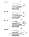
- Fig. 5 is a diagram comparing cross-sectional shapes of the vibrating element 11 of the present embodiment with a vibrating element 51 according to the comparative example.
- Fig. 5A is a cross-sectional diagram showing the vibrating element 51 of the comparative example
- Fig. 5B is a cross-sectional diagram showing the vibrating element 11 of the present embodiment.
- Fig. 5C and Fig. 5D are cross-sectional diagrams showing vibrating elements 11A and 11B according to other embodiments.
- the vibrating element 51 of the comparative example in Fig. 5A and the vibrating element 11 of the present embodiment in Fig. 5B will be described.
- the vibrating element 51 includes a substantially annular resilient body 52 and the piezoelectric body 13, which is joined to the resilient body 52.
- the flexible printed circuit board 14 is connected with the piezoelectric body 13.
- the resilient body 52 includes a combtooth portion 52a, a base portion 52b and a flange portion 52c.
- the vibrating element 51 of the comparative example has substantially the same form as the vibrating element 11 of the present embodiment, and is used in a similar ultrasonic motor driven by the same driving signals as the ultrasonic motor 10 of the present embodiment, but differs from the vibrating element 11 of the present embodiment in that no protrusion portion is formed at the resilient body 52. Accordingly, the same reference numerals and reference numerals with the same suffixes will be applied to portions having similar functions, and duplicative descriptions will be omitted as appropriate.
- Fig. 6 is a diagram describing the natural vibration modes of vibrating elements.
- Fig. 6A shows the natural vibration modes of the vibrating element 51 of the comparative example and
- Fig. 6B shows the natural vibration modes of the vibrating element 11 of the present embodiment.
- the vertical axes are absolute values of impedance and the horizontal axes are frequencies.
- the vibrating element 51 of the comparative example has a vibration mode A1 with a resonance frequency of 65 kHz.
- This vibration mode A1 is a bending vibration in which peaks and troughs of bending are arranged in the direction in which the moving element is driven, that is, the circumferential direction of the resilient body 52, and is a fourth-order bending vibration in which four vibrations with the same period occur in the resilient body 52.
- the vibrating element 51 of the comparative example also has a vibration mode B1, which is a vibration mode different from the vibration mode A1, in a frequency region corresponding to about twice the resonance frequency of the vibration mode A1.
- This vibration mode B1 is a fourth-order torsional vibration, and the resonance frequency thereof is 139 kHz.
- This fourth-order torsional vibration is concentric with the resilient body 52 and is a torsional vibration in which an imaginary circle, which passes through a substantially central position of width in the radial direction of the resilient body 52 and passes through a vicinity of the neutral plane of the aforementioned fourth-order bending vibration, vibrates about a torsion center. Four vibrations occur in the resilient body 52.
- a predetermined frequency region at the high frequency side or low frequency side relative to the resonance frequency of the vibration mode used for driving, is used for driving signals in the form of a region of driving frequencies to be used for driving (hereinafter referred to as a driving band).
- the reason for providing width to the driving frequencies which serve as the driving band is to enable alteration of the rotary speed of the moving element and control of the ultrasonic motor, by enabling alterations of driving frequency within the driving band.
- the high frequency side of the resonance frequency of the vibration mode used for driving is used as the driving band.
- Fig. 7 is diagrams showing relationships between rotary speeds and driving frequencies of the moving elements.
- Fig. 7A is an example of an ultrasonic motor using the vibrating element 51 of the comparative example
- Fig. 7B is an example of the ultrasonic motor 10 using the vibrating element 11 of the present embodiment.
- the vertical axes are rotary speeds of the moving elements and the horizontal axes are driving frequencies.
- a driving signal with an asymmetric waveform the same as in the present embodiment is applied.
- the driving signal is frequency-swept in the driving band required for driving, as shown in Fig. 7A , a frequency region D1 in which the rotary speed suddenly changes occurs (hereinafter referred to as a discontinuous region). If this discontinuous region D1 occurs in the driving band, driving of the ultrasonic motor is unstable, and control thereof is difficult.
- a sine wave for the driving signal driving an ultrasonic motor. If a driving signal is a sine wave, then when this driving signal is frequency-analyzed, only a single frequency is a detected frequency. Therefore, when a sine wave driving signal is applied to an ultrasonic motor, only vibrations of a vibration mode with a resonance frequency at a frequency close to the driving frequency of the driving signal are generated. Therefore, driving of the ultrasonic motor is stable, and control is easy to perform.
- a driving signal uses a symmetric waveform such as a rectangular wave or the like, or a waveform such as an asymmetric waveform as shown in Fig. 4 or the like.
- Fig. 8 is diagrams showing relationships between waveforms and higher harmonics of driving signals.
- the vertical axes are gains and the horizontal axes are frequencies.
- Fig. 8A shows a case in which the waveform of a driving signal is a symmetric signal (for example, a rectangular wave), and
- Fig. 8B shows a case in which the waveform of a driving signal is an asymmetric signal.
- the waveform of a driving signal is a symmetric waveform about zero potential, such as a rectangular wave, a sawtooth wave or the like, and this driving signal is frequency-analyzed, then as shown in Fig. 8A , beside the driving frequency (the frequency used for driving, which is 70 kHz in Fig. 8A ), higher harmonics with frequency values which are odd-number multiples of the driving frequency are detected: a higher harmonic frequency at three times the driving frequency (210 kHz), a higher harmonic frequency at five times the driving frequency (350 kHz), and so forth.
- a higher harmonic frequency at two times the driving frequency 140 kHz
- a higher harmonic frequency at three times the driving frequency 210 kHz
- a driving signal with a symmetric waveform includes, in addition to the driving frequency, higher harmonic frequencies which are odd-number multiples of the driving frequency
- a driving signal with an asymmetric waveform includes, in addition to the driving frequency, higher harmonic frequencies which are integer multiples of the driving frequency
- a driving signal applied to an ultrasonic motor is a symmetric waveform such as a rectangular wave, a sawtooth wave or the like
- the vibrating element has, in addition to the vibration mode used for driving, a vibration mode with a resonance frequency close to the frequency of a higher harmonic that is an odd-number multiple of the driving frequency, then, in addition to the vibration mode used for driving, the vibration mode with the resonance frequency close to the higher harmonic frequency at the odd-number multiple of the driving frequency is excited by the higher harmonics of the driving frequency included in the driving signal.
- a driving signal applied to an ultrasonic motor is an asymmetric waveform
- the vibrating element has, in addition to the vibration mode used for driving, a vibration mode with a resonance frequency close to the frequency of a higher harmonic that is an integer number multiple of the driving frequency, then, in addition to the vibration mode used for driving, the vibration mode with the resonance frequency close to the higher harmonic frequency at the integer multiple of the driving frequency is excited by the higher harmonics of the driving frequency included in the driving signal.
- the asymmetric waveform driving signal that is applied to the ultrasonic motor that uses the vibrating element 51 of the comparative example includes a higher harmonic frequency (140 kHz) at twice the driving frequency (70 kHz), which is close to the resonance frequency (139 kHz) of vibration mode B1 (see Fig. 6A ). Therefore, when the driving signal is frequency-swept within the driving band, the vibration mode B1 which is not used for driving is excited by the higher harmonic at twice the driving frequency, propagation of driving force from the progressive waves of the vibrating element 51 to the moving element is impeded, the discontinuous region D1 as shown in Fig. 7A arises, and driving is not stable.
- the protrusion portion 12d is provided at the resilient body 12 of the vibrating element 11.
- this vibrating element 11 has the vibration mode A2 and the vibration mode B2.
- Vibration mode A2 is a fourth-order bending vibration similar to vibration mode A1, and the resonance frequency thereof is 67 kHz.
- Vibration mode B2 is a fourth-order torsional vibration similar to vibration mode B1, and the resonance frequency thereof is 161 kHz.
- the protrusion portion 12d is at the inner diametric side of the resilient body 12 and is provided at the piezoelectric body 13 side relative to the center of thickness of the resilient body 12. This is a position which is close to the neutral plane of the fourth-order bending vibration of vibration mode A2, which is used for driving, and distant from the neutral axis of the fourth-order torsional vibration of vibration mode B2.
- the resonance frequency of vibration mode B2 can be altered to a frequency that is not affected by the higher harmonic frequency at twice the driving frequency.
- the resonance frequency of vibration mode A2 which is used for driving is also altered, but the alteration amount thereof is small and is within a range that has no effect on driving.
- the driving signal applied to the ultrasonic motor 10 is an asymmetric waveform as shown in Fig. 4 and includes the higher harmonic frequency at twice the driving frequency
- the resonance frequency of vibration mode B2 (161 kHz) is at a position which is distant from the higher harmonic frequency (140 kHz) at twice the driving frequency. Therefore, the vibration mode B2 is hardly excited at all.
- Fig. 7B although the discontinuous region D2 due to the vibration mode B2 does occur, this is for a case of performing a frequency sweep of the driving signal outside the driving band. Within the driving band, the ultrasonic motor 10 can be stably driven.
- the resonance frequency of a vibration mode that is not used for driving is a frequency that is not excited by a higher harmonic of the driving frequency when the driving signal is frequency-swept within the driving band.
- the left side of this expression represents a difference between the resonance frequency of vibration mode A and 1/m of the resonance frequency of vibration mode B.
- the right side of this expression represents the width of a driving band used for driving, which is 0.4 times the difference between the resonance frequency of vibration mode A that is used for driving (the fourth-order mode of bending) and a resonance frequency neighboring the resonance frequency of vibration mode A (a fifth-order mode of bending).
- the resonance frequency frc is 90 kHz
- Fig. 6B with the vibrating element 11 of the present embodiment, it is 92 kHz.
- the driving signal is an asymmetric waveform, and the vibration mode which is excited by the higher harmonic at twice the driving frequency has an effect on driving of the ultrasonic motor.
- m is set to 2
- values of the resonance frequencies are substituted into the above-described expression (1) in relation to the vibrating element 51 of the comparative example:
- vibration mode B1 will be excited by the higher harmonic frequency at twice the driving frequency.
- vibration mode B2 will be not excited by the higher harmonic frequency at twice the driving frequency.
- the discontinuous region D1 does not occur within the driving band as with the ultrasonic motor that uses the vibrating element 51 of the comparative example, and stable driving is possible.
- the vibrating element 11 of Fig. 5B has been described. However, the same effects as with the vibrating element 11 are also present if a vibrating element 11A of Fig. 5C or a vibrating element 11B of Fig. 5D is used.
- the vibrating element 11A and the vibrating element 11B are structures in which a protrusion portion is provided to the vibrating element of the comparative example 51, but the positions at which the protrusion portions are provided differ from the vibrating element 11.
- a protrusion portion 12e is provided at the base portion 12b of the resilient body 12A.
- the protrusion portion 12e is at the inner diametric side of the base portion 12b, and is provided at the combtooth portion 12a side of the flange portion 12c.
- a protrusion portion 12f is provided at the outer periphery side of the base portion 12b of a resilient body 12B. The positions at which the protrusion portions 12e and 12f are provided, similarly to the protrusion portion 12d of Fig.
- the vibrating elements of Fig. 5B to 5D may be produced in their respective shapes by mechanical machining.
- a vibrating element of a shape of Figs. 5B to 5D may be fabricated by fabricating a vibrating element without a protrusion portion as in the comparative example of Fig. 5A , fabricating a member with an annular shape corresponding to the protrusion portion of Figs. 5B to 5D , and sticking the two together.
- vibrating elements of numerous types may be fabricated by sticking any protrusion portion onto the vibrating element of Fig. 5A .
- the driving signal that is applied is an asymmetric waveform and the driving signal is frequency-swept in the driving band, frequencies of higher harmonics that are integer multiples of the driving frequency do not overlap with resonance frequencies of vibration modes that are not used for driving.
- the ultrasonic motor 10 of the present embodiment would be able to drive stably.
- the higher harmonic frequencies included in a driving signal with an asymmetric waveform are higher harmonic frequencies at odd-number multiples of the resonance frequency, and when the driving signal is frequency-swept in the driving band for the ultrasonic motor 10 of the present embodiment, the frequencies of higher harmonics at integer multiples of the resonant frequency, which include the odd-number multiples of the resonance frequency, do not overlap with the frequency of a vibration mode that is not used for driving.
- a vibration mode that is not used for driving is not excited by higher harmonic frequencies of driving frequencies, and an ultrasonic motor capable of stable driving can be formed.
Landscapes
- Physics & Mathematics (AREA)
- General Physics & Mathematics (AREA)
- Optics & Photonics (AREA)
- Engineering & Computer Science (AREA)
- General Engineering & Computer Science (AREA)
- General Electrical Machinery Utilizing Piezoelectricity, Electrostriction Or Magnetostriction (AREA)
Claims (19)
- Schwingungssaktuator (10), mit:einem schwingenden Element (11, 11A, 11B), das aufgrund eines Steuersignals schwingt; undeinem sich relativ bewegenden Element (15), das aufgrund der Schwingungen in Bezug auf das schwingende Element eine Relativbewegung ausführt, wobeidas schwingende Element imstande ist, in einer ersten Schwingungsform, die zum Antreiben des sich relativ bewegenden Elements verwendet wird, und in einer zweiten Schwingungsform zu schwingen, die eine Schwingungsform ist, welche sich von der ersten Schwingungsform unterscheidet, undeine Resonanzfrequenz der zweiten Schwingung nicht mit einer Frequenz einer Oberschwingung einer Steuerfrequenz des Steuersignals zum Antreiben des schwingenden Elements in der ersten Schwingungsform übereinstimmt,dadurch gekennzeichnet, dass der Schwingungssaktuator (10) ferner aufweist:einen frequenzabhängigen Regelabschnitt (12d, 12e, 12f), der einen Unterschied zwischen der Resonanzfrequenz der ersten Schwingungsform und der Resonanzfrequenz der zweiten Schwingungsform regelt.
- Schwingungssaktuator (10) nach Anspruch 1, bei dem
eine Resonanzfrequenz der zweiten Schwingungsform nicht mit einem Bereich überlappt, in dem sich die Frequenz der Oberschwingung verändert, wenn die Steuerfrequenz in einem Steuerfrequenzbereich verändert wird, der zum Steuern des sich relativ bewegenden Elements (15) verwendet wird. - Schwingungssaktuator (10) nach Anspruch 1 oder 2, bei dem die folgende Beziehung erfüllt wird

bei der fr1 eine Resonanzfrequenz der ersten Schwingungsform ist, fr2 die Resonanzfrequenz einer zweiten Schwingungsform ist, fr3 eine Resonanzfrequenz der ersten Schwingungsform des schwingenden Elements ist, die benachbart zu fr1 auf deren hochfrequenten oder niederfrequenten Seite ist, und m ein beliebiger ganzzahliger Wert ist. - Schwingungssaktuator (10) nach Anspruch 3, bei dem m=2.
- Schwingungssaktuator (10) nach Anspruch 3 oder 4, bei dem die folgende Beziehung erfüllt ist

- Schwingungssaktuator (10) nach einem der Ansprüche 1 bis 5, bei dem
die zweite Schwingungsform von der gleichen Ordnung ist wie die erste Schwingungsform. - Schwingungssaktuator (10) nach einem der Ansprüche 1 bis 6, bei dem
das Steuersignal eine asymmetrische Wellenform ist. - Schwingungssaktuator (10) nach einem der Ansprüche 1 bis 6, bei dem
das Steuersignal eine asymmetrische Wellenform ist und
die Resonanzfrequenz der zweiten Schwingungsform nicht mit der Frequenz einer Oberschwingung übereinstimmt, die ein mehrfach Ganzzahliges der Steuerfrequenz ist. - Schwingungssaktuator (10) nach einem der Ansprüche 1 bis 6, bei dem
das Steuersignal eine symmetrische Wellenform ist und
die zweite Schwingungsform nicht mit der Frequenz einer Oberschwingung übereinstimmt, die eine mehrfache ungleiche Anzahl der Steuerfrequenz ist. - Schwingungssaktuator (10) nach einem der Ansprüche 1 bis 9, bei dem
das schwingende Element (11, 11A, 11B) von im Wesentlichen ringförmiger Form ist,
die erste Schwingungsform eine Deformationsschwingung ist und
die zweite Schwingungsform eine Torsionsschwingung ist. - Schwingungssaktuator (10) nach einem der Ansprüche 1 bis 9, bei dem
das schwingende Element (11, 11A, 11B) von im Wesentlichen ringförmiger Form ist und einen randförmigen Flanschabschnitt (12c) aufweist, der zu einer Innendurchmesserseite hervorsteht. - Schwingungssaktuator (10) nach Anspruch 11, bei dem das schwingende Element (11, 11A, 11B) ferner aufweist:einen federnden Körper (12, 12A, 12B) und ein elektromechanisches Wandlerelement, das mit dem federnden Körper verbunden ist, und wobei der frequenzabhängige Regelabschnitt (12d, 12e, 12f) bei dem federnden Körper bereitgestellt ist.
- Schwingungssaktuator (10) nach Anspruch 12, bei dem
der frequenzabhängige Regelabschnitt (12d, 12e, 12f) von einer Fläche hervorstehend bereitgestellt ist, die den federnden Körper (12, 12A, 12B) mit dem elektromechanischen Wandlerelement verbindet. - Schwingungssaktuator (10) nach einem der Ansprüche 1 bis 11, bei dem
der frequenzabhängige Regelabschnitt (12d, 12e, 12f) bei dem schwingenden Element (11, 11A, 11B) bereitgestellt ist und ein Abschnitt ist, der in einer zu einer Ebene parallelen Richtung bereitgestellt ist, die eine Kontaktfläche aufweist, bei der das schwingende Element das sich relativ bewegende Element (15) berührt. - Schwingungssaktuator (10) nach einem der Ansprüche 1 bis 14, bei dem
der frequenzabhängige Regelabschnitt (12d, 12e, 12f) bei einer Position nahe einer neutralen Position der ersten Schwingungsform des schwingenden Elements (11, 11A, 11B) bereitgestellt ist. - Schwingungssaktuator (10) nach einem der Ansprüche 1 bis 15, bei dem
der frequenzabhängige Regelabschnitt (12d, 12e, 12f) bei einer Position bereitgestellt ist, die von einer neutralen Position der zweiten Schwingungsform des schwingenden Elements (11, 11A, 11B) entfernt ist. - Objektivtubus (3), der mit dem Schwingungssaktuator (10) nach einem der Ansprüche 1 bis 16 bereitgestellt ist.
- Kamerasystem, das mit dem Schwingungssaktuator (10) nach einem der Ansprüche 1 bis 16 bereitgestellt ist.
- Schwingendes Element zur Verwendung in einem Schwingungssaktuator (10), bei dem das schwingende Element:imstande ist, in einer ersten Schwingungsform, die zum Steuern des Schwingungssaktuators verwendet wird, und in einer zweiten Schwingungsform zu schwingen, die sich von der ersten Schwingungsform unterscheidet, und die folgende Beziehung erfüllt ist
 bei der fr1 eine Resonanzfrequenz der ersten Schwingungsform ist, fr2 eine Resonanzfrequenz der zweiten Schwingungsform ist, fr3 eine Resonanzfrequenz der ersten Schwingungsform des schwingenden Elements ist, die benachbart zu fr1 auf deren hochfrequenten oder niederfrequenten Seite ist, und m eine beliebige ganze Zahl ist,dadurch gekennzeichnet, dass das schwingende Element aufweist:einen frequenzabhängigen Regelabschnitt (12d, 12e, 12f), der einen Unterschied zwischen der Resonanzfrequenz der ersten Schwingungsform und der Resonanzfrequenz der zweiten Schwingungsform regelt.
Applications Claiming Priority (2)
| Application Number | Priority Date | Filing Date | Title |
|---|---|---|---|
| JP2006067233 | 2006-03-13 | ||
| PCT/JP2007/054677 WO2007105632A1 (ja) | 2006-03-13 | 2007-03-09 | 振動アクチュエータ、レンズ鏡筒、カメラシステム、振動子 |
Publications (3)
| Publication Number | Publication Date |
|---|---|
| EP1998433A1 EP1998433A1 (de) | 2008-12-03 |
| EP1998433A4 EP1998433A4 (de) | 2012-09-26 |
| EP1998433B1 true EP1998433B1 (de) | 2014-06-25 |
Family
ID=38509455
Family Applications (1)
| Application Number | Title | Priority Date | Filing Date |
|---|---|---|---|
| EP07738162.2A Not-in-force EP1998433B1 (de) | 2006-03-13 | 2007-03-09 | Vibrations-stellglied, linsentubus, kamerasystem und vibrator |
Country Status (6)
| Country | Link |
|---|---|
| US (1) | US8035275B2 (de) |
| EP (1) | EP1998433B1 (de) |
| JP (1) | JP4941469B2 (de) |
| KR (1) | KR101339645B1 (de) |
| CN (1) | CN101401291B (de) |
| WO (1) | WO2007105632A1 (de) |
Families Citing this family (8)
| Publication number | Priority date | Publication date | Assignee | Title |
|---|---|---|---|---|
| JP5262170B2 (ja) * | 2008-02-19 | 2013-08-14 | 株式会社ニコン | レンズ鏡筒、カメラ |
| JP5885380B2 (ja) | 2010-01-28 | 2016-03-15 | キヤノン株式会社 | 振動波駆動装置の駆動制御装置及び駆動制御方法 |
| JP5506552B2 (ja) | 2010-06-07 | 2014-05-28 | キヤノン株式会社 | 振動型アクチュエータの制御装置及び振動型アクチュエータの制御方法 |
| JP5978646B2 (ja) * | 2012-02-22 | 2016-08-24 | 株式会社ニコン | 振動波モータ、レンズ鏡筒、カメラ及び振動波モータの制御方法 |
| JP6184063B2 (ja) * | 2012-06-22 | 2017-08-23 | キヤノン株式会社 | 振動波駆動装置および電子機器 |
| JP6468735B2 (ja) | 2013-07-04 | 2019-02-13 | キヤノン株式会社 | 振動型駆動装置、画像形成装置、及びロボット |
| FR3042660B1 (fr) * | 2015-10-16 | 2018-04-06 | Airbus Helicopters | Actionneur electromecanique pour commandes de vol electriques d'un aeronef |
| JP7146425B2 (ja) * | 2018-03-19 | 2022-10-04 | ソニーグループ株式会社 | 情報処理装置、情報処理方法及び記録媒体 |
Family Cites Families (9)
| Publication number | Priority date | Publication date | Assignee | Title |
|---|---|---|---|---|
| US4812697A (en) * | 1986-04-09 | 1989-03-14 | Taga Electric Co., Ltd. | Ultrasonic vibrator and a method of controllingly driving same |
| DE3852224T2 (de) * | 1987-07-14 | 1995-04-06 | Honda Electric Co | Ultraschalltreiberanordnung. |
| EP0415657A3 (en) * | 1989-08-31 | 1991-12-04 | Kohji Toda | Vibrator-type actuator |
| JP3269223B2 (ja) * | 1993-10-15 | 2002-03-25 | 株式会社ニコン | 超音波モータと振動検出器とを備えた装置 |
| JPH09163767A (ja) | 1995-12-07 | 1997-06-20 | Nikon Corp | 振動アクチュエータの駆動装置 |
| TW344912B (en) * | 1996-06-05 | 1998-11-11 | Toshiba Co Ltd | Multifunctional ultrasonic motor and apparatus using the motor |
| JP3226894B2 (ja) * | 1999-03-25 | 2001-11-05 | セイコーインスツルメンツ株式会社 | 超音波モータ及び超音波モータ付き電子機器 |
| US20030052574A1 (en) * | 2001-09-07 | 2003-03-20 | Yukihiro Matsushita | Ultrasonic motor and method for manufacturing the same |
| JP2004187465A (ja) * | 2002-12-06 | 2004-07-02 | Canon Inc | 振動型アクチュエータ |
-
2007
- 2007-03-09 JP JP2008505113A patent/JP4941469B2/ja not_active Expired - Fee Related
- 2007-03-09 EP EP07738162.2A patent/EP1998433B1/de not_active Not-in-force
- 2007-03-09 US US12/224,947 patent/US8035275B2/en active Active
- 2007-03-09 KR KR1020087008919A patent/KR101339645B1/ko not_active Expired - Fee Related
- 2007-03-09 CN CN2007800085050A patent/CN101401291B/zh not_active Expired - Fee Related
- 2007-03-09 WO PCT/JP2007/054677 patent/WO2007105632A1/ja not_active Ceased
Also Published As
| Publication number | Publication date |
|---|---|
| EP1998433A1 (de) | 2008-12-03 |
| US8035275B2 (en) | 2011-10-11 |
| JPWO2007105632A1 (ja) | 2009-07-30 |
| KR101339645B1 (ko) | 2013-12-11 |
| US20090134745A1 (en) | 2009-05-28 |
| KR20080108075A (ko) | 2008-12-11 |
| WO2007105632A1 (ja) | 2007-09-20 |
| CN101401291B (zh) | 2012-05-30 |
| EP1998433A4 (de) | 2012-09-26 |
| CN101401291A (zh) | 2009-04-01 |
| JP4941469B2 (ja) | 2012-05-30 |
Similar Documents
| Publication | Publication Date | Title |
|---|---|---|
| US8035275B2 (en) | Vibration actuator, lens barrel, camera system and vibrating element | |
| JP4141990B2 (ja) | 圧電アクチュエータおよび機器 | |
| JP6056224B2 (ja) | 振動波モータ | |
| JP2008253078A (ja) | 電気機械変換素子,振動アクチュエータ,振動アクチュエータの駆動装置,レンズ鏡筒及びカメラ | |
| JP2025083553A (ja) | 振動波モータ | |
| KR20100083783A (ko) | 진동 액추에이터 및 촬상 장치 | |
| US8159763B2 (en) | Vibrating element, vibration actuator, lens barrel, camera system and method for driving vibration actuator | |
| JP2009201322A (ja) | 振動アクチュエータ、レンズ鏡筒、カメラ、振動アクチュエータの製造方法 | |
| CN102158124A (zh) | 振动波马达、透镜镜筒及相机 | |
| JP2009201191A (ja) | 振動アクチュエータ、レンズ鏡筒、カメラ | |
| JP5541281B2 (ja) | 振動アクチュエータ、レンズ鏡筒及びカメラ | |
| JP5273915B2 (ja) | 振動型リニア駆動装置及びカメラレンズ | |
| JP5534668B2 (ja) | 駆動装置及び駆動方法 | |
| JP5381241B2 (ja) | 振動アクチュエータ、レンズ鏡筒及びカメラ | |
| JP5736646B2 (ja) | 振動波モータ、レンズ鏡筒及びカメラ | |
| JP6221521B2 (ja) | 振動波モータ及び光学機器 | |
| JP2013247800A (ja) | 振動波モータの駆動装置、レンズ鏡筒及びカメラ | |
| JP5978646B2 (ja) | 振動波モータ、レンズ鏡筒、カメラ及び振動波モータの制御方法 | |
| JPH112752A (ja) | 振動アクチュエータ駆動装置とレンズ鏡筒 | |
| JP2022125212A (ja) | 振動型駆動装置、振動型駆動装置の制御方法、プログラム、ロボット、撮像装置の雲台及び画像形成装置 | |
| JP2021016271A (ja) | 振動体を用いた駆動装置およびその制御方法 | |
| US20190386583A1 (en) | Vibration wave motor and apparatus incorporating same | |
| JP6012226B2 (ja) | 振動波駆動装置及びその駆動回路 | |
| JP2003339177A (ja) | 超音波モータ及び超音波モータつき電子機器 | |
| JP2011109787A (ja) | 振動アクチュエータ、レンズ鏡筒及びカメラ |
Legal Events
| Date | Code | Title | Description |
|---|---|---|---|
| PUAI | Public reference made under article 153(3) epc to a published international application that has entered the european phase |
Free format text: ORIGINAL CODE: 0009012 |
|
| 17P | Request for examination filed |
Effective date: 20080929 |
|
| AK | Designated contracting states |
Kind code of ref document: A1 Designated state(s): AT BE BG CH CY CZ DE DK EE ES FI FR GB GR HU IE IS IT LI LT LU LV MC MT NL PL PT RO SE SI SK TR |
|
| RAP1 | Party data changed (applicant data changed or rights of an application transferred) |
Owner name: NIKON CORPORATION |
|
| DAX | Request for extension of the european patent (deleted) | ||
| A4 | Supplementary search report drawn up and despatched |
Effective date: 20120824 |
|
| RIC1 | Information provided on ipc code assigned before grant |
Ipc: H02N 2/00 20060101AFI20120820BHEP |
|
| REG | Reference to a national code |
Ref country code: DE Ref legal event code: R079 Ref document number: 602007037326 Country of ref document: DE Free format text: PREVIOUS MAIN CLASS: H02N0002000000 Ipc: G02B0007080000 |
|
| RIC1 | Information provided on ipc code assigned before grant |
Ipc: G02B 7/08 20060101AFI20131105BHEP Ipc: H02N 2/14 20060101ALI20131105BHEP |
|
| GRAP | Despatch of communication of intention to grant a patent |
Free format text: ORIGINAL CODE: EPIDOSNIGR1 |
|
| INTG | Intention to grant announced |
Effective date: 20140117 |
|
| RIN1 | Information on inventor provided before grant (corrected) |
Inventor name: ASHIZAWA, TAKATOSHI |
|
| GRAS | Grant fee paid |
Free format text: ORIGINAL CODE: EPIDOSNIGR3 |
|
| GRAA | (expected) grant |
Free format text: ORIGINAL CODE: 0009210 |
|
| AK | Designated contracting states |
Kind code of ref document: B1 Designated state(s): AT BE BG CH CY CZ DE DK EE ES FI FR GB GR HU IE IS IT LI LT LU LV MC MT NL PL PT RO SE SI SK TR |
|
| REG | Reference to a national code |
Ref country code: GB Ref legal event code: FG4D |
|
| REG | Reference to a national code |
Ref country code: CH Ref legal event code: EP |
|
| REG | Reference to a national code |
Ref country code: AT Ref legal event code: REF Ref document number: 675020 Country of ref document: AT Kind code of ref document: T Effective date: 20140715 |
|
| REG | Reference to a national code |
Ref country code: IE Ref legal event code: FG4D |
|
| REG | Reference to a national code |
Ref country code: DE Ref legal event code: R096 Ref document number: 602007037326 Country of ref document: DE Effective date: 20140807 |
|
| PG25 | Lapsed in a contracting state [announced via postgrant information from national office to epo] |
Ref country code: FI Free format text: LAPSE BECAUSE OF FAILURE TO SUBMIT A TRANSLATION OF THE DESCRIPTION OR TO PAY THE FEE WITHIN THE PRESCRIBED TIME-LIMIT Effective date: 20140625 Ref country code: LT Free format text: LAPSE BECAUSE OF FAILURE TO SUBMIT A TRANSLATION OF THE DESCRIPTION OR TO PAY THE FEE WITHIN THE PRESCRIBED TIME-LIMIT Effective date: 20140625 Ref country code: CY Free format text: LAPSE BECAUSE OF FAILURE TO SUBMIT A TRANSLATION OF THE DESCRIPTION OR TO PAY THE FEE WITHIN THE PRESCRIBED TIME-LIMIT Effective date: 20140625 Ref country code: GR Free format text: LAPSE BECAUSE OF FAILURE TO SUBMIT A TRANSLATION OF THE DESCRIPTION OR TO PAY THE FEE WITHIN THE PRESCRIBED TIME-LIMIT Effective date: 20140926 |
|
| REG | Reference to a national code |
Ref country code: AT Ref legal event code: MK05 Ref document number: 675020 Country of ref document: AT Kind code of ref document: T Effective date: 20140625 |
|
| REG | Reference to a national code |
Ref country code: NL Ref legal event code: VDEP Effective date: 20140625 |
|
| REG | Reference to a national code |
Ref country code: LT Ref legal event code: MG4D |
|
| PG25 | Lapsed in a contracting state [announced via postgrant information from national office to epo] |
Ref country code: SE Free format text: LAPSE BECAUSE OF FAILURE TO SUBMIT A TRANSLATION OF THE DESCRIPTION OR TO PAY THE FEE WITHIN THE PRESCRIBED TIME-LIMIT Effective date: 20140625 Ref country code: LV Free format text: LAPSE BECAUSE OF FAILURE TO SUBMIT A TRANSLATION OF THE DESCRIPTION OR TO PAY THE FEE WITHIN THE PRESCRIBED TIME-LIMIT Effective date: 20140625 |
|
| PG25 | Lapsed in a contracting state [announced via postgrant information from national office to epo] |
Ref country code: EE Free format text: LAPSE BECAUSE OF FAILURE TO SUBMIT A TRANSLATION OF THE DESCRIPTION OR TO PAY THE FEE WITHIN THE PRESCRIBED TIME-LIMIT Effective date: 20140625 Ref country code: ES Free format text: LAPSE BECAUSE OF FAILURE TO SUBMIT A TRANSLATION OF THE DESCRIPTION OR TO PAY THE FEE WITHIN THE PRESCRIBED TIME-LIMIT Effective date: 20140625 Ref country code: CZ Free format text: LAPSE BECAUSE OF FAILURE TO SUBMIT A TRANSLATION OF THE DESCRIPTION OR TO PAY THE FEE WITHIN THE PRESCRIBED TIME-LIMIT Effective date: 20140625 Ref country code: PT Free format text: LAPSE BECAUSE OF FAILURE TO SUBMIT A TRANSLATION OF THE DESCRIPTION OR TO PAY THE FEE WITHIN THE PRESCRIBED TIME-LIMIT Effective date: 20141027 Ref country code: SK Free format text: LAPSE BECAUSE OF FAILURE TO SUBMIT A TRANSLATION OF THE DESCRIPTION OR TO PAY THE FEE WITHIN THE PRESCRIBED TIME-LIMIT Effective date: 20140625 Ref country code: RO Free format text: LAPSE BECAUSE OF FAILURE TO SUBMIT A TRANSLATION OF THE DESCRIPTION OR TO PAY THE FEE WITHIN THE PRESCRIBED TIME-LIMIT Effective date: 20140625 |
|
| PG25 | Lapsed in a contracting state [announced via postgrant information from national office to epo] |
Ref country code: NL Free format text: LAPSE BECAUSE OF FAILURE TO SUBMIT A TRANSLATION OF THE DESCRIPTION OR TO PAY THE FEE WITHIN THE PRESCRIBED TIME-LIMIT Effective date: 20140625 Ref country code: AT Free format text: LAPSE BECAUSE OF FAILURE TO SUBMIT A TRANSLATION OF THE DESCRIPTION OR TO PAY THE FEE WITHIN THE PRESCRIBED TIME-LIMIT Effective date: 20140625 Ref country code: IS Free format text: LAPSE BECAUSE OF FAILURE TO SUBMIT A TRANSLATION OF THE DESCRIPTION OR TO PAY THE FEE WITHIN THE PRESCRIBED TIME-LIMIT Effective date: 20141025 Ref country code: PL Free format text: LAPSE BECAUSE OF FAILURE TO SUBMIT A TRANSLATION OF THE DESCRIPTION OR TO PAY THE FEE WITHIN THE PRESCRIBED TIME-LIMIT Effective date: 20140625 |
|
| REG | Reference to a national code |
Ref country code: DE Ref legal event code: R097 Ref document number: 602007037326 Country of ref document: DE |
|
| PG25 | Lapsed in a contracting state [announced via postgrant information from national office to epo] |
Ref country code: IT Free format text: LAPSE BECAUSE OF FAILURE TO SUBMIT A TRANSLATION OF THE DESCRIPTION OR TO PAY THE FEE WITHIN THE PRESCRIBED TIME-LIMIT Effective date: 20140625 Ref country code: DK Free format text: LAPSE BECAUSE OF FAILURE TO SUBMIT A TRANSLATION OF THE DESCRIPTION OR TO PAY THE FEE WITHIN THE PRESCRIBED TIME-LIMIT Effective date: 20140625 |
|
| PLBE | No opposition filed within time limit |
Free format text: ORIGINAL CODE: 0009261 |
|
| STAA | Information on the status of an ep patent application or granted ep patent |
Free format text: STATUS: NO OPPOSITION FILED WITHIN TIME LIMIT |
|
| 26N | No opposition filed |
Effective date: 20150326 |
|
| PG25 | Lapsed in a contracting state [announced via postgrant information from national office to epo] |
Ref country code: BE Free format text: LAPSE BECAUSE OF FAILURE TO SUBMIT A TRANSLATION OF THE DESCRIPTION OR TO PAY THE FEE WITHIN THE PRESCRIBED TIME-LIMIT Effective date: 20140625 |
|
| PG25 | Lapsed in a contracting state [announced via postgrant information from national office to epo] |
Ref country code: LU Free format text: LAPSE BECAUSE OF FAILURE TO SUBMIT A TRANSLATION OF THE DESCRIPTION OR TO PAY THE FEE WITHIN THE PRESCRIBED TIME-LIMIT Effective date: 20150309 Ref country code: MC Free format text: LAPSE BECAUSE OF FAILURE TO SUBMIT A TRANSLATION OF THE DESCRIPTION OR TO PAY THE FEE WITHIN THE PRESCRIBED TIME-LIMIT Effective date: 20140625 |
|
| REG | Reference to a national code |
Ref country code: CH Ref legal event code: PL |
|
| PG25 | Lapsed in a contracting state [announced via postgrant information from national office to epo] |
Ref country code: SI Free format text: LAPSE BECAUSE OF FAILURE TO SUBMIT A TRANSLATION OF THE DESCRIPTION OR TO PAY THE FEE WITHIN THE PRESCRIBED TIME-LIMIT Effective date: 20140625 |
|
| REG | Reference to a national code |
Ref country code: IE Ref legal event code: MM4A |
|
| PG25 | Lapsed in a contracting state [announced via postgrant information from national office to epo] |
Ref country code: IE Free format text: LAPSE BECAUSE OF NON-PAYMENT OF DUE FEES Effective date: 20150309 Ref country code: CH Free format text: LAPSE BECAUSE OF NON-PAYMENT OF DUE FEES Effective date: 20150331 Ref country code: LI Free format text: LAPSE BECAUSE OF NON-PAYMENT OF DUE FEES Effective date: 20150331 |
|
| REG | Reference to a national code |
Ref country code: FR Ref legal event code: PLFP Year of fee payment: 10 |
|
| PG25 | Lapsed in a contracting state [announced via postgrant information from national office to epo] |
Ref country code: MT Free format text: LAPSE BECAUSE OF FAILURE TO SUBMIT A TRANSLATION OF THE DESCRIPTION OR TO PAY THE FEE WITHIN THE PRESCRIBED TIME-LIMIT Effective date: 20140625 |
|
| REG | Reference to a national code |
Ref country code: FR Ref legal event code: PLFP Year of fee payment: 11 |
|
| PG25 | Lapsed in a contracting state [announced via postgrant information from national office to epo] |
Ref country code: BG Free format text: LAPSE BECAUSE OF FAILURE TO SUBMIT A TRANSLATION OF THE DESCRIPTION OR TO PAY THE FEE WITHIN THE PRESCRIBED TIME-LIMIT Effective date: 20140625 Ref country code: HU Free format text: LAPSE BECAUSE OF FAILURE TO SUBMIT A TRANSLATION OF THE DESCRIPTION OR TO PAY THE FEE WITHIN THE PRESCRIBED TIME-LIMIT; INVALID AB INITIO Effective date: 20070309 |
|
| PG25 | Lapsed in a contracting state [announced via postgrant information from national office to epo] |
Ref country code: TR Free format text: LAPSE BECAUSE OF FAILURE TO SUBMIT A TRANSLATION OF THE DESCRIPTION OR TO PAY THE FEE WITHIN THE PRESCRIBED TIME-LIMIT Effective date: 20140625 |
|
| REG | Reference to a national code |
Ref country code: FR Ref legal event code: PLFP Year of fee payment: 12 |
|
| PGFP | Annual fee paid to national office [announced via postgrant information from national office to epo] |
Ref country code: GB Payment date: 20200226 Year of fee payment: 14 Ref country code: DE Payment date: 20200225 Year of fee payment: 14 |
|
| PGFP | Annual fee paid to national office [announced via postgrant information from national office to epo] |
Ref country code: FR Payment date: 20200214 Year of fee payment: 14 |
|
| REG | Reference to a national code |
Ref country code: DE Ref legal event code: R119 Ref document number: 602007037326 Country of ref document: DE |
|
| GBPC | Gb: european patent ceased through non-payment of renewal fee |
Effective date: 20210309 |
|
| PG25 | Lapsed in a contracting state [announced via postgrant information from national office to epo] |
Ref country code: DE Free format text: LAPSE BECAUSE OF NON-PAYMENT OF DUE FEES Effective date: 20211001 Ref country code: GB Free format text: LAPSE BECAUSE OF NON-PAYMENT OF DUE FEES Effective date: 20210309 Ref country code: FR Free format text: LAPSE BECAUSE OF NON-PAYMENT OF DUE FEES Effective date: 20210331 |