EP1998168A1 - Hydrogen gas detector - Google Patents
Hydrogen gas detector Download PDFInfo
- Publication number
- EP1998168A1 EP1998168A1 EP20070714285 EP07714285A EP1998168A1 EP 1998168 A1 EP1998168 A1 EP 1998168A1 EP 20070714285 EP20070714285 EP 20070714285 EP 07714285 A EP07714285 A EP 07714285A EP 1998168 A1 EP1998168 A1 EP 1998168A1
- Authority
- EP
- European Patent Office
- Prior art keywords
- hydrogen gas
- hydrogen
- light
- optical
- substrate
- Prior art date
- Legal status (The legal status is an assumption and is not a legal conclusion. Google has not performed a legal analysis and makes no representation as to the accuracy of the status listed.)
- Withdrawn
Links
- UFHFLCQGNIYNRP-UHFFFAOYSA-N Hydrogen Chemical compound [H][H] UFHFLCQGNIYNRP-UHFFFAOYSA-N 0.000 claims abstract description 156
- 230000003287 optical effect Effects 0.000 claims abstract description 122
- 229910052739 hydrogen Inorganic materials 0.000 claims abstract description 120
- 239000001257 hydrogen Substances 0.000 claims abstract description 120
- 150000002431 hydrogen Chemical class 0.000 claims abstract description 115
- 238000001514 detection method Methods 0.000 claims abstract description 91
- 239000010408 film Substances 0.000 claims description 63
- 239000000758 substrate Substances 0.000 claims description 45
- 239000010409 thin film Substances 0.000 claims description 41
- 239000003054 catalyst Substances 0.000 claims description 23
- 230000005540 biological transmission Effects 0.000 claims description 6
- 230000001678 irradiating effect Effects 0.000 claims description 2
- 230000007423 decrease Effects 0.000 description 7
- 239000013307 optical fiber Substances 0.000 description 7
- 238000004880 explosion Methods 0.000 description 5
- 239000000463 material Substances 0.000 description 5
- 238000010276 construction Methods 0.000 description 3
- 238000010438 heat treatment Methods 0.000 description 3
- CURLTUGMZLYLDI-UHFFFAOYSA-N Carbon dioxide Chemical compound O=C=O CURLTUGMZLYLDI-UHFFFAOYSA-N 0.000 description 2
- KDLHZDBZIXYQEI-UHFFFAOYSA-N Palladium Chemical compound [Pd] KDLHZDBZIXYQEI-UHFFFAOYSA-N 0.000 description 2
- 239000004698 Polyethylene Substances 0.000 description 2
- 239000000446 fuel Substances 0.000 description 2
- 239000000203 mixture Substances 0.000 description 2
- BASFCYQUMIYNBI-UHFFFAOYSA-N platinum Chemical compound [Pt] BASFCYQUMIYNBI-UHFFFAOYSA-N 0.000 description 2
- -1 polyethylene Polymers 0.000 description 2
- 229920000573 polyethylene Polymers 0.000 description 2
- 230000035945 sensitivity Effects 0.000 description 2
- 238000002834 transmittance Methods 0.000 description 2
- 229920000178 Acrylic resin Polymers 0.000 description 1
- 239000004925 Acrylic resin Substances 0.000 description 1
- FYYHWMGAXLPEAU-UHFFFAOYSA-N Magnesium Chemical compound [Mg] FYYHWMGAXLPEAU-UHFFFAOYSA-N 0.000 description 1
- 229910000990 Ni alloy Inorganic materials 0.000 description 1
- 229910002092 carbon dioxide Inorganic materials 0.000 description 1
- 239000001569 carbon dioxide Substances 0.000 description 1
- 239000011248 coating agent Substances 0.000 description 1
- 238000000576 coating method Methods 0.000 description 1
- 238000005566 electron beam evaporation Methods 0.000 description 1
- 239000011521 glass Substances 0.000 description 1
- 229910052749 magnesium Inorganic materials 0.000 description 1
- 239000011777 magnesium Substances 0.000 description 1
- ATTFYOXEMHAYAX-UHFFFAOYSA-N magnesium nickel Chemical compound [Mg].[Ni] ATTFYOXEMHAYAX-UHFFFAOYSA-N 0.000 description 1
- 229910052751 metal Inorganic materials 0.000 description 1
- 239000002184 metal Substances 0.000 description 1
- 229910052763 palladium Inorganic materials 0.000 description 1
- 238000007747 plating Methods 0.000 description 1
- 229910052697 platinum Inorganic materials 0.000 description 1
- 230000000644 propagated effect Effects 0.000 description 1
- 230000001902 propagating effect Effects 0.000 description 1
- 230000000452 restraining effect Effects 0.000 description 1
- 238000004544 sputter deposition Methods 0.000 description 1
- 238000007738 vacuum evaporation Methods 0.000 description 1
Images


Classifications
-
- G—PHYSICS
- G01—MEASURING; TESTING
- G01N—INVESTIGATING OR ANALYSING MATERIALS BY DETERMINING THEIR CHEMICAL OR PHYSICAL PROPERTIES
- G01N21/00—Investigating or analysing materials by the use of optical means, i.e. using sub-millimetre waves, infrared, visible or ultraviolet light
- G01N21/75—Systems in which material is subjected to a chemical reaction, the progress or the result of the reaction being investigated
- G01N21/77—Systems in which material is subjected to a chemical reaction, the progress or the result of the reaction being investigated by observing the effect on a chemical indicator
-
- G—PHYSICS
- G01—MEASURING; TESTING
- G01M—TESTING STATIC OR DYNAMIC BALANCE OF MACHINES OR STRUCTURES; TESTING OF STRUCTURES OR APPARATUS, NOT OTHERWISE PROVIDED FOR
- G01M3/00—Investigating fluid-tightness of structures
- G01M3/02—Investigating fluid-tightness of structures by using fluid or vacuum
- G01M3/04—Investigating fluid-tightness of structures by using fluid or vacuum by detecting the presence of fluid at the leakage point
- G01M3/20—Investigating fluid-tightness of structures by using fluid or vacuum by detecting the presence of fluid at the leakage point using special tracer materials, e.g. dye, fluorescent material, radioactive material
-
- G—PHYSICS
- G01—MEASURING; TESTING
- G01M—TESTING STATIC OR DYNAMIC BALANCE OF MACHINES OR STRUCTURES; TESTING OF STRUCTURES OR APPARATUS, NOT OTHERWISE PROVIDED FOR
- G01M3/00—Investigating fluid-tightness of structures
- G01M3/38—Investigating fluid-tightness of structures by using light
-
- G—PHYSICS
- G01—MEASURING; TESTING
- G01N—INVESTIGATING OR ANALYSING MATERIALS BY DETERMINING THEIR CHEMICAL OR PHYSICAL PROPERTIES
- G01N21/00—Investigating or analysing materials by the use of optical means, i.e. using sub-millimetre waves, infrared, visible or ultraviolet light
- G01N21/17—Systems in which incident light is modified in accordance with the properties of the material investigated
- G01N21/55—Specular reflectivity
-
- G—PHYSICS
- G01—MEASURING; TESTING
- G01N—INVESTIGATING OR ANALYSING MATERIALS BY DETERMINING THEIR CHEMICAL OR PHYSICAL PROPERTIES
- G01N21/00—Investigating or analysing materials by the use of optical means, i.e. using sub-millimetre waves, infrared, visible or ultraviolet light
- G01N21/17—Systems in which incident light is modified in accordance with the properties of the material investigated
- G01N21/59—Transmissivity
Definitions
- the present invention relates to a hydrogen gas detection device for detecting hydrogen gas.
- Hydrogen has been attracting attention as an energy source capable of restraining emission of carbon dioxide. There is a possibility, however, that if hydrogen gas leaks out into the surrounding atmosphere (e.g., an area around a hydrogen gas generation apparatus or hydrogen gas storage apparatus, or a parking lot where motor vehicles using hydrogen as fuel are parked), explosion will be caused. It is therefore necessary that leakage of hydrogen gas should be immediately detected and stopped.
- the surrounding atmosphere e.g., an area around a hydrogen gas generation apparatus or hydrogen gas storage apparatus, or a parking lot where motor vehicles using hydrogen as fuel are parked
- a hydrogen gas detection device has been contrived in which leakage hydrogen gas is detected by a hydrogen sensor heated by a heater.
- Hydrogen gas detection devices of this type are disclosed, for example, in Unexamined Japanese Patent Publications No. 2003-098147 and No. 2004-144564 .
- the hydrogen sensors used in these hydrogen gas detection devices cannot detect hydrogen unless they are heated to a high temperature of several hundred degrees Celsius.
- the possibility of a hydrogen gas explosion being induced by heat cannot be negated, making it necessary to take measures to prevent such explosion from being caused by the high-temperature heating.
- leakage hydrogen gas present around the hydrogen sensor can be detected, it is not possible to detect leakage hydrogen gas over a wide area (space).
- the present invention was created in view of the above circumstances, and an object thereof is to provide a hydrogen gas detection device whose hydrogen sensor need not be heated.
- Another object of the present invention is to provide a hydrogen gas detection device that does not require measures to be taken to prevent an explosion from being caused by high-temperature heating.
- Still another object of the present invention is to provide a hydrogen gas detection device capable of quickly and safely detecting leakage of hydrogen gas preferably over a wide area.
- the present invention provides a hydrogen gas detection device comprising: a hydrogen sensor whose reflectance varies upon contact with hydrogen gas; a light source for irradiating light onto the hydrogen sensor; and an optical sensor for receiving the light emitted from the light source and transmitted through or reflected by the hydrogen sensor, and for outputting a detection signal.
- the hydrogen sensor of the hydrogen gas detection device In a normal state in which no leakage hydrogen gas exists, the hydrogen sensor of the hydrogen gas detection device has high reflectance (or low reflectance). On the other hand, when exposed to an atmosphere containing more hydrogen gas than in the normal state, the reflectance of the hydrogen sensor decreases (or increases).
- the present invention provides a hydrogen gas detection device comprising: a light source for emitting light; an optical sensor for receiving the light and outputting a detection signal; and a plurality of hydrogen sensors for successively reflecting the light emitted from the light source to transmit the light to the optical sensor, wherein reflectance of each of the hydrogen sensors varies upon contact with hydrogen gas.
- this hydrogen gas detection device if leakage hydrogen gas reaches the vicinity of any one of the hydrogen sensors, the reflectance of this hydrogen sensor varies. The light from the light source is reflected successively by the multiple hydrogen sensors before reaching the optical sensor, and the amount of light received by the optical sensor varies due to the change of the reflectance. It is therefore possible to detect leakage of hydrogen gas over a wide area where the multiple hydrogen sensors are arranged, based on the detection signal output from the optical sensor and indicative of change in the amount of light received.
- the hydrogen sensor may include: a substrate capable of transmitting the light therethrough; and a reflective film whose reflectance varies upon contact with hydrogen gas.
- the reflective film may include: a thin-film layer formed on an obverse or reverse surface of the substrate; and a catalyst layer formed on a surface of the thin-film layer, the catalyst layer hydrogenating the thin-film layer upon contact with hydrogen gas to vary reflectance of the thin-film layer.
- the present invention provides a hydrogen gas detection device comprising: a hydrogen sensor including a substrate capable of transmitting light therethrough, a first reflective film formed on one surface of the substrate, a second reflective film formed on an opposite surface of the substrate, an optical input port for admitting light to one end of the substrate, and an optical output port for receiving the light that arrives at an opposite end of the substrate after being input from the optical input port and then reflected alternately by the first and second reflective films, and for allowing the received light to be output to outside of the substrate, wherein reflectance of either one or both of the first and second reflective films varies upon contact with hydrogen gas; a light source for inputting the light to the optical input port; and an optical sensor for receiving the light output from the optical output port and outputting a detection signal.
- this hydrogen gas detection device when the reflectance of one or both of the first and second reflective films decreases (or increases) due to contact with hydrogen gas, the light (amount of light) output from the optical output port decreases (or increases). Thus, leakage of hydrogen gas can be detected on the basis of the detection signal output from the optical sensor and corresponding to the amount of light received from the optical output port.
- the present invention provides a hydrogen gas detection device comprising: a plurality of hydrogen sensors each including a substrate capable of transmitting light therethrough, a first reflective film formed on one surface of the substrate, a second reflective film formed on an opposite surface of the substrate, an optical input port for admitting light to one end of the substrate, and an optical output port for receiving the light that arrives at an opposite end of the substrate after being input from the optical input port and then reflected alternately by the first and second reflective films, and for allowing the received light to be output to outside of the substrate, wherein reflectance of either one or both of the first and second reflective films varies upon contact with hydrogen gas; optical transmission means for cascade-connecting the hydrogen sensors to form an optical circuit; a light source for inputting the light to the optical input port of that one of the cascade-connected hydrogen sensors which is situated at an input end of the optical circuit; and an optical sensor for receiving the light output from the optical output port of that one of the cascade-connected hydrogen sensors which is situated at an output end of the optical circuit
- this hydrogen gas detection device if leakage hydrogen gas reaches the vicinity of any one of the hydrogen sensors, the light (amount of light) output from the optical output port of this hydrogen sensor varies. Since the multiple hydrogen sensors are cascade-connected by the optical transmission means to constitute the optical circuit, the amount of light reaching the optical sensor via the optical transmission means varies. It is therefore possible to detect leakage of hydrogen gas over a wide area where the multiple hydrogen sensors are arranged, based on the detection signal output from the optical sensor and indicative of change in the amount of light received.
- the first and/or second reflective film of which the reflectance varies upon contact with hydrogen gas may include: a thin-film layer formed on the corresponding surface of the substrate; and a catalyst layer formed on a surface of the thin-film layer, the catalyst layer hydrogenating the thin-film layer upon contact with hydrogen gas to vary reflectance of the thin-film layer.
- the hydrogen gas detection devices are each adapted to quickly detect change in the reflectance (optical reflectance) of the hydrogen sensor due to contact with hydrogen gas, by detecting change in the amount of light received by the optical sensor. It is therefore unnecessary to heat the hydrogen sensor, and thus, to take measures to prevent explosion from being induced by high-temperature heating. Accordingly, leakage of hydrogen gas can be detected quickly and safely, and where a plurality of hydrogen sensors are used, it is possible to detect leakage of hydrogen gas over a wide area.
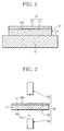
- FIGS. 1 and 2 schematically illustrates, in section, an exemplary construction of a hydrogen sensor
- FIG. 2 schematically illustrates an exemplary configuration of the hydrogen gas detection device of the first embodiment.
- the hydrogen sensor used in the hydrogen gas detection device will be described first.
- the hydrogen sensor 10 shown in FIG. 1 has a substrate 11 made of metal, glass, acrylic resin, or polyethylene sheet (polyethylene film).
- a thin-film layer 12 of magnesium-nickel alloy or magnesium is formed on a surface 11a of the substrate 11.
- a catalyst layer 13 of palladium or platinum is formed on a surface 12a of the thin-film layer 12.
- the thin-film layer 12 and the catalyst layer 13 constitute a reflective film 14 of the hydrogen sensor 10.
- the thin-film layer 12 may be formed by sputtering, vacuum evaporation, electron-beam evaporation or plating, and the composition thereof is, for example, MgNi x (0 ⁇ x ⁇ 0.6).
- the catalyst layer 13 is formed, for example, by being coated over the surface 12a of the thin-film layer 12 and has a thickness of 1 nm to 100 nm.
- the thin-film layer 12 forming part of the reflective film 14 is rapidly hydrogenated in several to approximately ten seconds. As a result, the reflectance of the thin-film layer 12 rapidly changes.
- compositions etc. of the thin-film layer 12 and the catalyst layer 13 are not limited to those mentioned above, and also the reflectance of the thin-film layer 12 is not limited to that within the range of visible light.
- the hydrogen gas detection device will be now described.
- FIG. 2 schematically illustrates an exemplary configuration of a hydrogen gas detection device 20 using the aforementioned hydrogen sensor 10.
- the hydrogen gas detection device 20 includes the hydrogen sensor 10, a light source 21, and an optical sensor 22.
- the light source 21 is arranged so as to face the reverse surface 10x of the hydrogen sensor 10 and irradiates light 21a emitted, for example, from a laser diode or light emitting diode incorporated therein toward the hydrogen sensor 10.
- the optical sensor 22 is so arranged as to face the obverse surface 10y of the hydrogen sensor 10 in alignment with an optical path of the light 21a transmitted through the hydrogen sensor 10.
- the optical sensor 22 includes a phototransistor or the like for receiving the light 21a transmitted through the hydrogen sensor 10 and outputs an electrical signal corresponding to the amount of light received.
- the transmittance of the reflective film 14 is low. Accordingly, the reflective film 14 of the hydrogen sensor 10 shows high reflectance and reflects the light 21a emitted from the light source 21. As a result, the electrical signal output from the optical sensor 22 has a low level.
- the light source 21 and the optical sensor 22 may alternatively be arranged so as to face the obverse and reverse surfaces 10y and 10x, respectively, of the hydrogen sensor 10.
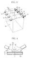
- a plurality of hydrogen gas detection devices each including the hydrogen sensor 10, the light source 21 and the optical sensor 22 may be used in combination, as shown in FIG. 3 .
- multiple devices each comprising the hydrogen sensor 10, the light source 21 and the optical sensor 22 may be arranged in an upper region of a space Q1 (e.g., parking space of an underground parking lot) that is formed into a substantially rectangular parallelepiped, as shown in FIG. 3 , for example.
- the hydrogen gas detection devices are disposed such that the light beams 21a emitted from the respective light sources 21 travel in parallel with one another at regular intervals.
- the amount of light transmitted through this hydrogen sensor 10 increases.
- the corresponding optical sensor 22 for detecting the light transmitted through this hydrogen sensor 10 outputs a high-level electrical signal. It is therefore possible to quickly detect leakage of hydrogen gas over a wide area.
- the positional relationship of respective sets of the hydrogen sensor 10, the light source 21 and the optical sensor 22 is of course not limited to the one shown in FIG. 3 .
- a hydrogen gas detection device according to a second embodiment of the present invention will be now described with reference to FIG. 4 .
- identical reference numerals are used to denote elements with identical functions already explained with reference to the first embodiment, and description of such elements is omitted.
- FIG. 4 schematically illustrates an exemplary configuration of the hydrogen gas detection device 20a according to the second embodiment.
- the light source 21 and the optical sensor 22 are both arranged on the same side as the obverse surface 10y of the hydrogen sensor 10.
- the light 21a emitted from the light source 21 falls upon the reflective film 14 of the hydrogen sensor 10 at an incidence angle ⁇ , as shown in FIG. 4 , then is reflected at the reflective film 14 and reaches the optical sensor 22.
- the reflective film 14 of the hydrogen sensor 10 has high reflectance with respect to the light 21a emitted from the light source 21. Accordingly, the optical sensor 22, which receives the reflected light, outputs a high-level electrical signal.
- the hydrogen sensor 10 to be used in the first and second embodiments is not limited to the illustrated one and may be modified in many ways without departing from the spirit of the present invention.
- the reflective film is not limited to the one whose reflectance lowers upon contact with hydrogen gas.
- a different type of reflective film may also be used of which the reflectance is, for example, low in the normal state in which no leakage hydrogen gas exists and increases upon contact with hydrogen gas.
- the light source 21 and the optical sensor 22 may be arranged on the same side as the reverse surface 10x of the hydrogen sensor 10. Further, where the substrate 11 does not transmit the light therethrough and has low reflectance, the light source 21 and the optical sensor 22 may be arranged on the same side as the reflective film 14 (on the obverse side 10y of the hydrogen sensor 10).
- a hydrogen gas detection device according to a third embodiment of the present invention will be now described with reference to FIG. 5 .
- identical reference numerals are used to denote elements with identical functions already explained with reference to the foregoing embodiments, and description of such elements is omitted.
- FIG. 5 schematically illustrates an exemplary configuration of the hydrogen gas detection device 20b according to the third embodiment.
- the hydrogen gas detection device 20b includes a set of four hydrogen sensors 10a to 10d arranged on an identical plane, and another set of three hydrogen sensors 10e to 10g arranged on a different plane parallel with the first-mentioned plane.
- the light source 21, the hydrogen sensors 10a to 10g and the optical sensor 22 are positioned such that the light 21a emitted from the light source 21 is reflected successively by the hydrogen sensors 10a, 10e, 10b, 10f, 10c, 10g and 10d and reaches the optical sensor 22.
- the individual reflective films 14 of the hydrogen sensors 10a to 10g have high reflectance. Accordingly, the light 21a emitted from the light source 21 reaches the optical sensor 22, which then outputs a high-level electrical signal.
- the hydrogen gas detection device 20b by comparing the level of the electrical signal output from the optical sensor 22 with a predetermined reference value in the hydrogen gas detection device 20b, it is possible to detect leakage of hydrogen gas. Also, the use of multiple hydrogen sensors enables the hydrogen gas detection device 20b to quickly detect leakage of hydrogen gas over a wide area.
- the arrangement of the light source 21, the hydrogen sensors 10 and the optical sensor 22 as well as the number of hydrogen sensors are not limited to the arrangement and the number explained above with reference to the third embodiment.
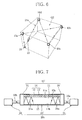
- the light source 21 may be arranged at one of the four lower corners of a space Q2 that is formed into a substantially rectangular parallelepiped, and four hydrogen sensors 10a to 10d may be arranged at the respective upper corners of the space Q2.
- the hydrogen gas detection device is configured such that the light 21a emitted upward from the light source 21 is reflected successively by the hydrogen sensors 10a to 10d to fall upon the optical sensor 22 located at an upper portion of one of the faces defining the space Q2.
- More hydrogen sensors 10 may be used to guide the light 21a emitted from the light source 21 to the optical sensor 22, and in this case, leakage of hydrogen gas can be quickly detected over a wider area.
- a hydrogen gas detection device according to a fourth embodiment of the present invention will be now described with reference to FIG. 7 .
- identical reference numerals are used to denote elements with identical functions already explained with reference to the foregoing embodiments, and description of such elements is omitted.
- FIG. 7 schematically illustrates an exemplary configuration of the hydrogen gas detection device 20c according to the fourth embodiment.
- the hydrogen gas detection device 20c has a hydrogen sensor 10' in which the thin-film layer 12 is formed on the obverse surface 11a of the substrate 11. Further, the catalyst layer 13 is formed on the surface 12a of the thin-film layer 12. When the catalyst layer 13 is exposed to hydrogen gas, the thin-film layer 12 is hydrogenated by the action of the catalyst layer 13, with the result that the reflectance of the thin-film layer 12 rapidly lowers.
- the substrate 11 has a reverse surface 11b coated with a second reflective film 15 having high reflectance.
- the thin-film layer 12 and the catalyst layer 13 constitute the first reflective film 14 of the hydrogen sensor 10'.
- An optical input port 30 is joined to the right-hand end of the hydrogen sensor 10' as viewed in FIG. 7 , and an optical output port 31 is joined to the left-hand end of the sensor 10'.
- the optical input port 30 is connected with an optical fiber 32a for admitting the light 21a emitted from the light source 21 into the optical input port 30.
- the light 21a thus admitted to the optical input port 30 is input to (guided into) the substrate 11 of the hydrogen sensor 10', then reflected alternately by the first and second reflective films 14 and 15 while propagating through the substrate 11, and reaches the optical output port 31.
- the light 21a arriving at the optical output port 31 is then transmitted to the optical sensor 22 through an optical fiber 32b connected to the optical output port 31.
- the first reflective film 14 of the hydrogen sensor 10' has high reflectance. Accordingly, the light 21a propagates through the substrate 11 while being repeatedly reflected by the first and second reflective films 14 and 15 and reaches the optical output port 31.
- the amount of light 21a arriving at the optical output port 31 shows a greater change in response to change in the reflectance of the first reflective film 14, so that the detection sensitivity of the hydrogen gas detection device 20c improves.
- the second reflective film 15 is constituted by the thin-film layer 12 and the catalyst layer 13, like the first reflective film 14, the reflectance of the second reflective film 15 also decreases on contact with hydrogen gas, so that the hydrogen gas detection sensitivity further improves.
- the light 21a is input to and output from the hydrogen sensor 10' through the respective optical fibers 32a and 32b, and there is no object that obstructs the propagation of the light 21a.
- the hydrogen sensor 10', the light source 21 and the optical sensor 22 can be positioned with high flexibility.
- the light source 21 may be connected directly to the optical input port 30 of the hydrogen sensor 10', and also the optical sensor 22 may be connected directly to the optical output port 31 of the hydrogen sensor 10'.
- the hydrogen sensor 10' to be used in the hydrogen gas detection device 20c of this embodiment is not limited to the aforementioned one and may be modified in many ways without departing from the spirit of the invention.
- the first reflective film 14 of the hydrogen sensor may have such reflectance that the reflectance is low in the normal state in which no leakage hydrogen gas exists and increases upon contact with hydrogen gas.
- a material that hardly absorbs light may be bonded to the substrate 11.
- Light is reflected at the reflection interface between the reverse surface 11b of the substrate 11 and the corresponding surface of the bonded material, and the reflection interface functions as a reflection surface only if the bonded material has a predetermined thickness or more.
- the predetermined thickness of the bonded material constitutes the reflective film.
- the reflective film 15 can therefore be formed by bonding a material that hardly absorbs light to the substrate 11.
- a hydrogen gas detection device according to a fifth embodiment of the present invention will be now described with reference to FIG. 8 .
- identical reference numerals are used to denote elements with identical functions already explained with reference to the foregoing embodiments, and description of such elements is omitted.
- the hydrogen gas detection device 20d shown in FIG. 8 includes four hydrogen sensors 10a' to 10d' (each having a construction identical with that of the hydrogen sensor 10').
- the four hydrogen sensors 10a' to 10d' are arranged at respective different locations and are cascade-connected by three optical fibers (optical transmission means) 32c to form an optical circuit 33.
- the light 21a emitted from the light source 21 is input to the optical circuit 33 through the optical fiber 32a connected to the optical input port 30 of the hydrogen sensor 10a' situated at the input end of the optical circuit 33.
- the input light 21a is propagated through the optical circuit 33 and output from the optical output port 31 of the hydrogen sensor 10d' situated at the output end of the optical circuit 33.
- the light 21a thus output from the optical output port 31 is transmitted through the optical fiber 32b to the optical sensor 22.
- the hydrogen sensors 10a' to 10d' are arranged, for example, in an upper region of the parking space of an underground parking lot to detect leakage of hydrogen gas from the hydrogen fuel cell vehicles parked in the parking space.
- the first reflective films 14 of the hydrogen sensors 10a' to 10d' each have high reflectance. Accordingly, the light 21a can reach the optical output port 31 of the hydrogen sensor at the output end.
- the light 21a is input to and output from the individual hydrogen sensors 10a' to 10d' through the optical fibers 32a, 32b and 32c, and there is no object that obstructs the propagation of the light 21a from the light source 21. Accordingly, the hydrogen sensors 10a' to 10d', the light source 21 and the optical sensor 22 can be arranged with high flexibility.
- the hydrogen sensors 10a' to 10d' to be used in the hydrogen gas detection device 20d of the fifth embodiment are not limited to the aforementioned one and may be modified in many ways without departing from the spirit of the invention.
- the second reflective film 15 may have a layered structure identical with that of the first reflective film 14 so that the reflectance of the second reflective film 15 may also lower upon contact with hydrogen gas.
- the configuration of the optical circuit is not limited to the illustrated one alone.
- the light emitted from a single light source may be split to be input to a plurality of optical circuits each including cascade-connected hydrogen sensors, and each optical circuit may be connected with an optical sensor.
Landscapes
- Physics & Mathematics (AREA)
- General Physics & Mathematics (AREA)
- Chemical & Material Sciences (AREA)
- Immunology (AREA)
- Life Sciences & Earth Sciences (AREA)
- Analytical Chemistry (AREA)
- Biochemistry (AREA)
- General Health & Medical Sciences (AREA)
- Health & Medical Sciences (AREA)
- Pathology (AREA)
- Engineering & Computer Science (AREA)
- Chemical Kinetics & Catalysis (AREA)
- Plasma & Fusion (AREA)
- Investigating Or Analysing Materials By The Use Of Chemical Reactions (AREA)
- Investigating Or Analysing Materials By Optical Means (AREA)
- Investigating Or Analyzing Materials By The Use Of Electric Means (AREA)
- Examining Or Testing Airtightness (AREA)
Applications Claiming Priority (2)
| Application Number | Priority Date | Filing Date | Title |
|---|---|---|---|
| JP2006074735A JP2007248367A (ja) | 2006-03-17 | 2006-03-17 | 水素ガス検知装置 |
| PCT/JP2007/052755 WO2007108261A1 (ja) | 2006-03-17 | 2007-02-15 | 水素ガス検知装置 |
Publications (1)
| Publication Number | Publication Date |
|---|---|
| EP1998168A1 true EP1998168A1 (en) | 2008-12-03 |
Family
ID=38522298
Family Applications (1)
| Application Number | Title | Priority Date | Filing Date |
|---|---|---|---|
| EP20070714285 Withdrawn EP1998168A1 (en) | 2006-03-17 | 2007-02-15 | Hydrogen gas detector |
Country Status (7)
Cited By (3)
| Publication number | Priority date | Publication date | Assignee | Title |
|---|---|---|---|---|
| CN103071358A (zh) * | 2012-12-27 | 2013-05-01 | 博益(天津)气动技术研究所有限公司 | 一种用于微小泄漏检测的氢气过滤器 |
| CN103913449A (zh) * | 2013-01-07 | 2014-07-09 | Nxp股份有限公司 | 集成电路与制造方法 |
| RU236082U1 (ru) * | 2025-01-14 | 2025-07-25 | Федеральное государственное бюджетное учреждение науки Институт экспериментальной минералогии имени академика Д.С. Коржинского Российской академии наук (ИЭМ РАН) | Детектор водорода |
Families Citing this family (16)
| Publication number | Priority date | Publication date | Assignee | Title |
|---|---|---|---|---|
| JP5164435B2 (ja) * | 2007-06-04 | 2013-03-21 | 株式会社アツミテック | 水素センサ |
| RU2368882C1 (ru) * | 2008-04-21 | 2009-09-27 | Общество с ограниченной ответственностью Научно-технический Центр "ТАТА"-ООО НТЦ "ТАТА" | Датчик взрывоопасных концентраций водорода |
| KR101105687B1 (ko) * | 2009-07-29 | 2012-01-18 | 한국광기술원 | 가스 검지용 광센서 모듈 및 그를 포함하는 가스 검지 시스템 |
| US8871671B2 (en) * | 2009-09-04 | 2014-10-28 | Kabushiki Kaisha Atsumitec | Hydrogen storage unit |
| US8547553B2 (en) * | 2010-03-17 | 2013-10-01 | General Electric Company | Fiber optic hydrogen purity sensor and system |
| JP5789357B2 (ja) * | 2010-04-14 | 2015-10-07 | 株式会社アツミテック | 水素センサ |
| JP2012021938A (ja) * | 2010-07-16 | 2012-02-02 | Japan Atomic Energy Agency | 環状飽和炭化水素化合物の検知素子及びそれを用いた光学式検知装置 |
| US8889422B2 (en) | 2011-02-17 | 2014-11-18 | General Electric Company | Optical gas sensor for use with electrical equipment and methods of assembling same |
| CN103454052B (zh) * | 2013-08-29 | 2017-03-01 | 上海华虹宏力半导体制造有限公司 | Mems器件及晶圆级密封性的测量方法 |
| WO2016184792A1 (en) * | 2015-05-18 | 2016-11-24 | Abb Technology Ag | Optical sensing system for determining hydrogen |
| CN107560805B (zh) * | 2017-07-24 | 2019-04-09 | 温州大学 | 一种燃气管道破裂漏气的检测装置 |
| CN110243789B (zh) * | 2019-06-28 | 2022-07-08 | 京东方科技集团股份有限公司 | 一种气体监测装置和气体监测方法,以及显示装置 |
| CN112649161A (zh) * | 2020-11-27 | 2021-04-13 | 宝武清洁能源有限公司 | 气敏色变传感器及基于气敏色变传感的加氢站安全盾系统 |
| US11802858B2 (en) | 2021-02-18 | 2023-10-31 | Aerodyne Research, Inc. | Rapid, sensitive hydrogen detector |
| US12339220B2 (en) | 2021-02-18 | 2025-06-24 | Aerodyne Research, Inc. | Rapid, sensitive hydrogen detector with flow path difference compensation |
| PL446328A1 (pl) | 2023-10-09 | 2025-04-14 | Akademia Górniczo-Hutnicza Im.Stanisława Staszica W Krakowie | Wgłębnik termoelektryczny i układ pomiarowy do pomiaru zawartości wodoru i mikrotwardości |
Family Cites Families (24)
| Publication number | Priority date | Publication date | Assignee | Title |
|---|---|---|---|---|
| JPS5879141A (ja) * | 1981-11-05 | 1983-05-12 | Hochiki Corp | 光学式ガス検知器 |
| CH665719A5 (de) | 1983-03-23 | 1988-05-31 | Cerberus Ag | Vorrichtung zum nachweis von gasfoermigen verunreinigungen in luft mittels eines gassensors. |
| JPS6039536A (ja) * | 1983-08-12 | 1985-03-01 | Hochiki Corp | ガスセンサ |
| US4560444A (en) * | 1983-12-29 | 1985-12-24 | Uop Inc. | Gas detection with novel electrolyte membrane and solid internal reference |
| JPS61201143A (ja) * | 1985-03-04 | 1986-09-05 | Agency Of Ind Science & Technol | 水素ガスセンサー |
| GB8614972D0 (en) * | 1986-06-19 | 1986-07-23 | Plessey Co Plc | Optical devices |
| US4962021A (en) * | 1986-06-20 | 1990-10-09 | Personal Diagnostics, Inc. | Analyte determination using gel including a reagent system reacts with analyte to change transmissive property of gel detectable by light beam transmitted through gel by total internal reflectance |
| JPH01193628A (ja) * | 1988-01-28 | 1989-08-03 | Hitachi Cable Ltd | 平均湿度の測定方法 |
| JPH01320451A (ja) | 1988-06-22 | 1989-12-26 | Ricoh Co Ltd | 気体検知装置 |
| JPH0499948A (ja) * | 1990-08-20 | 1992-03-31 | Tdk Corp | 光学的センシング回路 |
| JPH0510879A (ja) * | 1991-07-03 | 1993-01-19 | Mitsubishi Electric Corp | ガス検出ネツトワーク |
| JPH05307005A (ja) * | 1992-04-30 | 1993-11-19 | Ngk Spark Plug Co Ltd | 濃度測定用材及び濃度測定用材を用いた濃度測定装置 |
| JPH0798278A (ja) * | 1993-08-06 | 1995-04-11 | Tdk Corp | 化学物質センサ |
| JPH07243973A (ja) | 1994-03-04 | 1995-09-19 | Ebara Res Co Ltd | 酸性ガスまたはアルカリ性ガスの検知材及びその製造方法並びに検知装置 |
| JPH09113501A (ja) | 1995-10-16 | 1997-05-02 | Kurabe Ind Co Ltd | 一酸化炭素ガス検知用検知材料及び一酸化炭素ガス検知方法 |
| US5783152A (en) * | 1997-03-24 | 1998-07-21 | The United States Of America As Represented By The United States Department Of Energy | Thin-film fiber optic hydrogen and temperature sensor system |
| US6006582A (en) * | 1998-03-17 | 1999-12-28 | Advanced Technology Materials, Inc. | Hydrogen sensor utilizing rare earth metal thin film detection element |
| EP1234167A4 (en) * | 1999-11-18 | 2005-06-29 | Mst Technology Gmbh | OPTICAL DETECTOR OF HYDROGEN |
| JP2003098147A (ja) | 2001-09-25 | 2003-04-03 | Matsushita Electric Ind Co Ltd | 水素センサとそれを用いた自動車 |
| US7116421B2 (en) * | 2002-03-15 | 2006-10-03 | Jose Agustin Garcia | Device and method for differential sensing of hydrogen gas using thermoabsorptance or thermoreflectance |
| JP3707053B2 (ja) * | 2002-05-08 | 2005-10-19 | 慎司 岡崎 | ガスセンサ用の膜の製造方法 |
| JP2004093162A (ja) * | 2002-08-29 | 2004-03-25 | Casio Comput Co Ltd | 膜の水素透過性評価方法 |
| JP2004144564A (ja) | 2002-10-23 | 2004-05-20 | Nissan Motor Co Ltd | ガス検査装置及び燃料電池装置 |
| JP4164574B2 (ja) * | 2003-09-05 | 2008-10-15 | 独立行政法人産業技術総合研究所 | 光学反射率変化を用いる水素センサ、水素検出方法及び検出装置 |
-
2006
- 2006-03-17 JP JP2006074735A patent/JP2007248367A/ja active Pending
-
2007
- 2007-02-15 CN CN2007800177758A patent/CN101449146B/zh active Active
- 2007-02-15 CA CA2645591A patent/CA2645591C/en active Active
- 2007-02-15 EP EP20070714285 patent/EP1998168A1/en not_active Withdrawn
- 2007-02-15 KR KR20087022102A patent/KR20080106238A/ko not_active Ceased
- 2007-02-15 US US12/293,267 patent/US7852480B2/en active Active
- 2007-02-15 WO PCT/JP2007/052755 patent/WO2007108261A1/ja active Application Filing
Non-Patent Citations (1)
| Title |
|---|
| See references of WO2007108261A1 * |
Cited By (5)
| Publication number | Priority date | Publication date | Assignee | Title |
|---|---|---|---|---|
| CN103071358A (zh) * | 2012-12-27 | 2013-05-01 | 博益(天津)气动技术研究所有限公司 | 一种用于微小泄漏检测的氢气过滤器 |
| CN103913449A (zh) * | 2013-01-07 | 2014-07-09 | Nxp股份有限公司 | 集成电路与制造方法 |
| CN103913449B (zh) * | 2013-01-07 | 2017-01-11 | Nxp股份有限公司 | 集成电路与制造方法 |
| US9818905B2 (en) | 2013-01-07 | 2017-11-14 | Nxp B.V. | Integrated circuit and manufacturing method |
| RU236082U1 (ru) * | 2025-01-14 | 2025-07-25 | Федеральное государственное бюджетное учреждение науки Институт экспериментальной минералогии имени академика Д.С. Коржинского Российской академии наук (ИЭМ РАН) | Детектор водорода |
Also Published As
| Publication number | Publication date |
|---|---|
| US20090135425A1 (en) | 2009-05-28 |
| CN101449146A (zh) | 2009-06-03 |
| CA2645591A1 (en) | 2007-09-27 |
| JP2007248367A (ja) | 2007-09-27 |
| KR20080106238A (ko) | 2008-12-04 |
| US7852480B2 (en) | 2010-12-14 |
| CN101449146B (zh) | 2012-05-23 |
| CA2645591C (en) | 2015-05-12 |
| WO2007108261A1 (ja) | 2007-09-27 |
Similar Documents
| Publication | Publication Date | Title |
|---|---|---|
| CA2645591C (en) | Hydrogen gas detector | |
| US9366565B2 (en) | Light out-coupling arrangement and a touch sensitive system comprising the out-coupling arrangement | |
| US7612328B2 (en) | Foil-type pressure sensor | |
| KR101332974B1 (ko) | 수소센서 및 수소가스 검지장치 | |
| JPS60500984A (ja) | 電磁放射回路素子 | |
| US20080116378A1 (en) | Long-term stable optical sensor arrangement, especially a hydrogen sensor, and combined gas sensor arrangement | |
| JP2016176778A (ja) | 光学式水素ガス検知装置及び方法 | |
| Franke et al. | Review and evaluation of metal-hydride-based hydrogen sensors as safety devices for future sustainable aviation | |
| WO2013054118A1 (en) | Fluorescence gas and liquid sensor | |
| CN107949788A (zh) | 用于确定氢的光学感测系统 | |
| JP2000506974A (ja) | 光ファイバ式感知装置 | |
| JP5648892B2 (ja) | 光ファイバ水素センサ及びそれを備えた光ファイバ水素センサシステム | |
| KR100767535B1 (ko) | 연료전지용 광섬유 수소센서 | |
| US20150036125A1 (en) | Sensor for monitoring a medium | |
| US11585795B2 (en) | Optical detection type chemical sensor | |
| JP2005326269A (ja) | ガス検知の方法およびガス検知装置 | |
| JP2005233740A (ja) | 光検知式水素検出素子及び水素検出装置 | |
| CN101008615A (zh) | 使用耦合表面等离子体的表面等离子体共振生物传感器 | |
| WO1998001748A1 (fr) | Appareil de mesure du point de congelation et methode de mesure du point de congelation | |
| JP2006214886A (ja) | 光学素子の欠陥検出方法および欠陥検出装置 | |
| CN210322074U (zh) | 一种表面贴装式荧光光纤温度探头 | |
| JP3203793U (ja) | 錠剤検知装置 | |
| US20240019368A1 (en) | An optical measurement device | |
| JP2006058246A (ja) | 温度センサ | |
| JP2025009119A (ja) | 漏液センサ |
Legal Events
| Date | Code | Title | Description |
|---|---|---|---|
| PUAI | Public reference made under article 153(3) epc to a published international application that has entered the european phase |
Free format text: ORIGINAL CODE: 0009012 |
|
| 17P | Request for examination filed |
Effective date: 20080924 |
|
| AK | Designated contracting states |
Kind code of ref document: A1 Designated state(s): DE FR GB |
|
| RBV | Designated contracting states (corrected) |
Designated state(s): DE FR GB |
|
| DAX | Request for extension of the european patent (deleted) | ||
| STAA | Information on the status of an ep patent application or granted ep patent |
Free format text: STATUS: THE APPLICATION HAS BEEN WITHDRAWN |
|
| 18W | Application withdrawn |
Effective date: 20160118 |