EP1997875A1 - Biogasanlage zur Erzeugung von Biogas aus Biomasse sowie Verfahren zum Betreiben der Biogasanlage - Google Patents
Biogasanlage zur Erzeugung von Biogas aus Biomasse sowie Verfahren zum Betreiben der Biogasanlage Download PDFInfo
- Publication number
- EP1997875A1 EP1997875A1 EP08156915A EP08156915A EP1997875A1 EP 1997875 A1 EP1997875 A1 EP 1997875A1 EP 08156915 A EP08156915 A EP 08156915A EP 08156915 A EP08156915 A EP 08156915A EP 1997875 A1 EP1997875 A1 EP 1997875A1
- Authority
- EP
- European Patent Office
- Prior art keywords
- biogas
- exhaust gas
- fermenter
- outlet
- line
- Prior art date
- Legal status (The legal status is an assumption and is not a legal conclusion. Google has not performed a legal analysis and makes no representation as to the accuracy of the status listed.)
- Granted
Links
- 238000000034 method Methods 0.000 title claims abstract description 24
- 239000002028 Biomass Substances 0.000 title claims abstract description 19
- 239000007789 gas Substances 0.000 claims abstract description 149
- CURLTUGMZLYLDI-UHFFFAOYSA-N Carbon dioxide Chemical compound O=C=O CURLTUGMZLYLDI-UHFFFAOYSA-N 0.000 claims abstract description 66
- VNWKTOKETHGBQD-UHFFFAOYSA-N methane Chemical compound C VNWKTOKETHGBQD-UHFFFAOYSA-N 0.000 claims abstract description 62
- 229910002092 carbon dioxide Inorganic materials 0.000 claims abstract description 33
- 239000001569 carbon dioxide Substances 0.000 claims abstract description 33
- 238000010926 purge Methods 0.000 claims abstract description 32
- 239000000203 mixture Substances 0.000 claims abstract description 27
- 238000000855 fermentation Methods 0.000 claims abstract description 16
- 230000004151 fermentation Effects 0.000 claims abstract description 16
- 238000004519 manufacturing process Methods 0.000 claims abstract description 11
- 238000002485 combustion reaction Methods 0.000 claims abstract description 7
- 239000000446 fuel Substances 0.000 claims abstract description 6
- 239000002912 waste gas Substances 0.000 claims description 27
- 238000011068 loading method Methods 0.000 claims description 19
- FGUUSXIOTUKUDN-IBGZPJMESA-N C1(=CC=CC=C1)N1C2=C(NC([C@H](C1)NC=1OC(=NN=1)C1=CC=CC=C1)=O)C=CC=C2 Chemical compound C1(=CC=CC=C1)N1C2=C(NC([C@H](C1)NC=1OC(=NN=1)C1=CC=CC=C1)=O)C=CC=C2 FGUUSXIOTUKUDN-IBGZPJMESA-N 0.000 claims 1
- YTAHJIFKAKIKAV-XNMGPUDCSA-N [(1R)-3-morpholin-4-yl-1-phenylpropyl] N-[(3S)-2-oxo-5-phenyl-1,3-dihydro-1,4-benzodiazepin-3-yl]carbamate Chemical compound O=C1[C@H](N=C(C2=C(N1)C=CC=C2)C1=CC=CC=C1)NC(O[C@H](CCN1CCOCC1)C1=CC=CC=C1)=O YTAHJIFKAKIKAV-XNMGPUDCSA-N 0.000 claims 1
- 238000001514 detection method Methods 0.000 abstract description 2
- 238000010438 heat treatment Methods 0.000 abstract description 2
- 230000006012 detection of carbon dioxide Effects 0.000 abstract 1
- 239000003517 fume Substances 0.000 abstract 1
- 239000012071 phase Substances 0.000 description 11
- 239000000758 substrate Substances 0.000 description 5
- 239000000463 material Substances 0.000 description 4
- 239000002360 explosive Substances 0.000 description 2
- 239000007788 liquid Substances 0.000 description 2
- 239000000523 sample Substances 0.000 description 2
- 241000894006 Bacteria Species 0.000 description 1
- 239000000654 additive Substances 0.000 description 1
- 238000010923 batch production Methods 0.000 description 1
- 239000002361 compost Substances 0.000 description 1
- 238000009264 composting Methods 0.000 description 1
- 238000010276 construction Methods 0.000 description 1
- 238000009826 distribution Methods 0.000 description 1
- 230000005611 electricity Effects 0.000 description 1
- 230000007717 exclusion Effects 0.000 description 1
- 238000004880 explosion Methods 0.000 description 1
- 238000011010 flushing procedure Methods 0.000 description 1
- 238000011081 inoculation Methods 0.000 description 1
- 239000007791 liquid phase Substances 0.000 description 1
- 239000012528 membrane Substances 0.000 description 1
- 238000002156 mixing Methods 0.000 description 1
- 239000003345 natural gas Substances 0.000 description 1
- 238000005457 optimization Methods 0.000 description 1
- 239000003895 organic fertilizer Substances 0.000 description 1
- 238000005507 spraying Methods 0.000 description 1
- 238000011144 upstream manufacturing Methods 0.000 description 1
- 238000005406 washing Methods 0.000 description 1
- XLYOFNOQVPJJNP-UHFFFAOYSA-N water Substances O XLYOFNOQVPJJNP-UHFFFAOYSA-N 0.000 description 1
Images


Classifications
-
- C—CHEMISTRY; METALLURGY
- C12—BIOCHEMISTRY; BEER; SPIRITS; WINE; VINEGAR; MICROBIOLOGY; ENZYMOLOGY; MUTATION OR GENETIC ENGINEERING
- C12M—APPARATUS FOR ENZYMOLOGY OR MICROBIOLOGY; APPARATUS FOR CULTURING MICROORGANISMS FOR PRODUCING BIOMASS, FOR GROWING CELLS OR FOR OBTAINING FERMENTATION OR METABOLIC PRODUCTS, i.e. BIOREACTORS OR FERMENTERS
- C12M41/00—Means for regulation, monitoring, measurement or control, e.g. flow regulation
- C12M41/30—Means for regulation, monitoring, measurement or control, e.g. flow regulation of concentration
- C12M41/34—Means for regulation, monitoring, measurement or control, e.g. flow regulation of concentration of gas
-
- C—CHEMISTRY; METALLURGY
- C12—BIOCHEMISTRY; BEER; SPIRITS; WINE; VINEGAR; MICROBIOLOGY; ENZYMOLOGY; MUTATION OR GENETIC ENGINEERING
- C12M—APPARATUS FOR ENZYMOLOGY OR MICROBIOLOGY; APPARATUS FOR CULTURING MICROORGANISMS FOR PRODUCING BIOMASS, FOR GROWING CELLS OR FOR OBTAINING FERMENTATION OR METABOLIC PRODUCTS, i.e. BIOREACTORS OR FERMENTERS
- C12M21/00—Bioreactors or fermenters specially adapted for specific uses
- C12M21/04—Bioreactors or fermenters specially adapted for specific uses for producing gas, e.g. biogas
-
- C—CHEMISTRY; METALLURGY
- C12—BIOCHEMISTRY; BEER; SPIRITS; WINE; VINEGAR; MICROBIOLOGY; ENZYMOLOGY; MUTATION OR GENETIC ENGINEERING
- C12M—APPARATUS FOR ENZYMOLOGY OR MICROBIOLOGY; APPARATUS FOR CULTURING MICROORGANISMS FOR PRODUCING BIOMASS, FOR GROWING CELLS OR FOR OBTAINING FERMENTATION OR METABOLIC PRODUCTS, i.e. BIOREACTORS OR FERMENTERS
- C12M21/00—Bioreactors or fermenters specially adapted for specific uses
- C12M21/16—Solid state fermenters, e.g. for koji production
-
- C—CHEMISTRY; METALLURGY
- C12—BIOCHEMISTRY; BEER; SPIRITS; WINE; VINEGAR; MICROBIOLOGY; ENZYMOLOGY; MUTATION OR GENETIC ENGINEERING
- C12M—APPARATUS FOR ENZYMOLOGY OR MICROBIOLOGY; APPARATUS FOR CULTURING MICROORGANISMS FOR PRODUCING BIOMASS, FOR GROWING CELLS OR FOR OBTAINING FERMENTATION OR METABOLIC PRODUCTS, i.e. BIOREACTORS OR FERMENTERS
- C12M23/00—Constructional details, e.g. recesses, hinges
- C12M23/36—Means for collection or storage of gas; Gas holders
-
- C—CHEMISTRY; METALLURGY
- C12—BIOCHEMISTRY; BEER; SPIRITS; WINE; VINEGAR; MICROBIOLOGY; ENZYMOLOGY; MUTATION OR GENETIC ENGINEERING
- C12M—APPARATUS FOR ENZYMOLOGY OR MICROBIOLOGY; APPARATUS FOR CULTURING MICROORGANISMS FOR PRODUCING BIOMASS, FOR GROWING CELLS OR FOR OBTAINING FERMENTATION OR METABOLIC PRODUCTS, i.e. BIOREACTORS OR FERMENTERS
- C12M41/00—Means for regulation, monitoring, measurement or control, e.g. flow regulation
- C12M41/48—Automatic or computerized control
-
- Y—GENERAL TAGGING OF NEW TECHNOLOGICAL DEVELOPMENTS; GENERAL TAGGING OF CROSS-SECTIONAL TECHNOLOGIES SPANNING OVER SEVERAL SECTIONS OF THE IPC; TECHNICAL SUBJECTS COVERED BY FORMER USPC CROSS-REFERENCE ART COLLECTIONS [XRACs] AND DIGESTS
- Y02—TECHNOLOGIES OR APPLICATIONS FOR MITIGATION OR ADAPTATION AGAINST CLIMATE CHANGE
- Y02E—REDUCTION OF GREENHOUSE GAS [GHG] EMISSIONS, RELATED TO ENERGY GENERATION, TRANSMISSION OR DISTRIBUTION
- Y02E50/00—Technologies for the production of fuel of non-fossil origin
- Y02E50/30—Fuel from waste, e.g. synthetic alcohol or diesel
Definitions
- the invention relates to a biogas plant for the production of biogas from biomass with at least one fermenter according to claim 1 and a method for switching off a fermenter according to claim 10 and a method for starting a fermenter according to claim 14.
- dry fermentation makes it possible to methanize pourable biomass from agriculture, biowaste and communal care areas without transferring the materials into a pumpable, liquid substrate. It can be fermented biomasses with up to 50% dry matter content. This dry fermentation process is for example in the EP 0 934 998 described.
- the material to be fermented is not stirred into a liquid phase, as is the case, for example, with the liquid fermentation of biowaste.
- the fermentation substrate introduced into the fermenter is kept constantly moist by withdrawing the percolate from the fermenter bottom and re-spraying it over the biomass. This ensures optimal living conditions for the bacteria.
- the recirculation of the percolate can be used to regulate the temperature, and it is possible to add additives for process optimization.
- WO 02/06439 From the WO 02/06439 is a bioreactor or a fermenter in the form of a Fartiggarage known which is operated according to the principle of dry fermentation in the so-called batch process.
- the fermentation substrate is filled with wheel loaders in the fermenter.
- the garage-shaped fermentation tank is closed with a gas-tight door.
- the biomass is fermented under exclusion of air, there is no further mixing and it is fed to any additional material.
- That from the fermentation Sipping percolate is withdrawn via a drainage channel, temporarily stored in a tank and sprayed over the fermentation substrate for humidification.
- the fermentation process takes place in the mesophilic temperature range at 34-37 ° C, the temperature is controlled by a floor and wall heating.
- the resulting biogas can be used in a combined heat and power plant to generate electricity and heat.
- several fermentation tanks are operated at different times in the dry fermentation plant.
- the fermenter room is completely emptied and then refilled.
- the fermented substrate is supplied to a post-composting, so that a conventional compost comparable organic fertilizer is produced.
- the individual fermenters Due to the batch mode, the individual fermenters have to be switched off from time to time. H. the biogas production must be stopped, the fermented biomass must be taken from the respective fermenter and fresh biomass must be filled into the fermenter and the biogas production must be resumed. For safety reasons, an explosive biogas / air mixture must be prevented during unloading and loading of the individual fermenters.
- the biogas plant according to claim 1 comprises the necessary components to enable a safe shutdown and unloading as well as a safe startup of a fermenter.
- the biogas production and utilization is maintained as long as possible during shutdown and purging with carbon dioxide-containing exhaust gas, d. H. the biogas / waste gas mixture of the fermenter to be switched off is supplied to the biogas consumer until the quality of this mixture falls below a predetermined level. Only when the methane concentration in the biogas outlet falls below an upper limit, the leading to the biogas consumer biogas line is separated from the biogas outlet. Thereafter, the only little methane-containing biogas / exhaust gas mixture is discharged through a vent stack. This is done until the methane concentration has dropped to a lower limit, in which almost no more methane is contained in the biogas / exhaust gas mixture.
- the digester to be shut down is purged with fresh air instead of carbon dioxide-containing exhaust gas and the exhaust / biogas / fresh air mixture is removed via the exhaust chimney until the carbon dioxide concentration in the exhaust / biogas / fresh air mixture has dropped to a first limit. Only then is the fermenter opened to discharge the spent biomass and to recharge the fermenter with fresh biomass. The preceding rinsing with exhaust gas and fresh air, the opening and unloading and loading of the fermenter without danger to the operator is possible.
- the biogas / exhaust gas mixture is not discharged through the exhaust chimney on reaching the upper limit of the methane concentration to the environment, but fed to an exhaust gas flare and flared there, If necessary, the exhaust gas flare can be supplied with additional fuel, so that in each case a combustion takes place.
- the flaring of the biogas / exhaust gas mixture takes place until the methane concentration in the biogas / waste gas mixture falls below an average limit value which lies between the upper and the lower limit value.
- fresh air is sucked in during the unloading and loading of the switched-off biofermenter via the open loading and unloading and the aspirated gas mixture is fed to the exhaust chimney via the purge gas inlet or via the biogas outlet.
- a special Frischluftabsaugan gleich be provided in the fermenter.
- the advantageous embodiment of the invention according to claim 13 ensures that fresh air is continuously drawn during unloading and loading of the fermenter
- the inventive method for (re) start the shut-off fermenter according to claim 14 and 15 is reliably prevented that when starting an explosive biogas / air mixture is formed.
- the exhaust gas for flushing the fermenter to be switched off is provided, for example, by an internal combustion engine.
- the carbon dioxide-containing exhaust gas is provided from a biogas upgrading device connected downstream of the at least one fermenter.
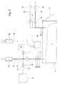
- FIGS. 1 to 7 show a first embodiment of a biogas plant according to the present invention with a single fermenter 2.
- the fermenter 2 is cuboid and has approximately the construction of a prefabricated garage. Via a loading and unloading opening 4, which extends over one of the front sides of the cuboid fermenter 2, biomass 6 can be filled into the fermenter 2 by means of a wheel loader and removed again. With regard to the exact structure of the fermenter 2 is on the WO 02/06439 directed.
- the fermenter 2 further comprises a biogas outlet 8, which can be connected via valves 10 to a biogas line 12, a first biogas / waste gas line 14 and a second biogas / waste gas line 16.
- the biogas line 12 leads to a combined heat and power plant 18 as a biogas utilization facility.
- the first biogas / waste gas line 14 leads to an exhaust gas chimney 20.
- the second biogas / waste gas line 16 leads to an exhaust gas flare 22.
- the fermenter 2 comprises a purge gas inlet 24 which can be connected via valves 10 to an exhaust gas line 26 or a fresh air line 28 is.
- an exhaust fan 27 is arranged, can be pumped by means of the exhaust gas in the fermenter 2.
- a fresh air blower 29 is arranged for sucking fresh air from the environment.
- About the exhaust pipe 26 is carbon dioxide-containing exhaust gas as purge gas and the fresh air line 28 fresh air is fed into the fermenter 2.
- the valves 10 are connected to a control device 30 and are opened or closed by the control device 30.
- the control device 30 is also connected to a first measuring sensor 32, which is arranged in the biogas outlet 8 and detects the methane concentration in the respective gas mixture.
- the control device 30 is further connected to a second measuring sensor 34, which is likewise arranged in the biogas outlet 8 and detects the carbon dioxide concentration in the respective gas mixture.
- the control device 30 is also connected to a third measuring sensor 36, which is arranged in the biogas outlet 8 and detects the gas volume flow in the biogas outlet. Via a blower 38 arranged in the biogas outlet, the withdrawal of gas from the fermenter 2 can optionally be assisted.
- FIGS. 1 to 7 different stages of shutdown and startup of the fermenter 2 are shown, wherein active lines and positions of components are shown in solid lines, while non-active or locked lines and positions of components are shown in broken lines.
- Fig. 1 shows the first phase of the shutdown of the fermenter 2 is pumped in the carbon dioxide-containing exhaust gas via the exhaust pipe 26 and the purge gas inlet 24 into the interior of the fermenter 2.
- the biogas outlet 8 is still connected to the biogas line 12, so that the biogas / waste gas mixture is further supplied to the CHP 18.
- valve 10 in the biogas line 12 is closed by the control device 30 and the valve 10 in the second biogas / exhaust gas line 16 open like this in Fig. 2 is shown.
- the biogas / waste gas mixture in the exhaust gas flare 22 is burned.
- this combustion process may be assisted by the addition of additional fuel.
- the valve 10 in the second biogas / exhaust conduit 16 is closed by the controller 30 and the valve 10 in the first biogas / exhaust conduit 14 will be opened as shown in Fig. 3 is shown.
- the biogas / waste gas mixture is discharged through the exhaust stack 20 to the environment.
- valve 10 in the exhaust line 26 is closed by the controller 30 and the valve 10 in the fresh air line 28 is opened as shown in FIG Fig. 4 is shown.
- fresh air is pumped into the fermenter 2 via the fresh air line 28 and the purge gas inlet 24.
- the exhaust gas / air mixture is further discharged via the biogas outlet 8 and the first biogas / exhaust gas line 14 in the exhaust stack 20 to the environment.
- valve 10 is closed in the fresh air line 28 by the controller 30 and the loading and unloading 4 open, as shown in Fig. 5 is shown.
- 38 fresh air is sucked in via the open loading and unloading through the fan and discharged through the exhaust stack 20 to the environment. In this way it is prevented that biogas residues still contained in the fermented biomass during unloading represent a danger for the operating personnel.
- the loading and unloading 4 is closed, the connection between the biogas outlet 8 and the exhaust stack 20 via the first biogas / exhaust gas line 14 is maintained and the controller 30 opens the valve 10 in the exhaust pipe 26, so the carbon dioxide-containing exhaust gas is pumped into the fermenter 2 - see Fig. 6 , This is continued until the detected by the second sensor 34 carbon dioxide concentration in the biogas outlet 8 reaches or exceeds a second threshold.
- control device 30 closes the valve 10 in the exhaust gas line 26 and in the first biogas / exhaust gas line 14 and opens the valve 10 in the biogas line 12, as shown in FIG Fig. 7 is shown.
- the phase of biogas production is reached again and the biogas produced in the fermenter 2 is fed via the biogas line 12 to the CHP 18.
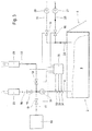
- Fig. 8 shows an alternative embodiment of the invention, which differs from the embodiment according to the Fig. 1 to 7 differs in that the first and second biogas / exhaust gas line 14, 16 are combined to form a common biogas / exhaust gas line 40 before they open into the biogas outlet 8, the second.
- Sensor for detecting the carbon dioxide concentration is arranged in the common biogas / exhaust gas line 40 and the third sensor 36 is disposed in the first biogas / exhaust gas line 14. Otherwise, this second embodiment of the invention is consistent with the first embodiment. The functionality is identical as well.
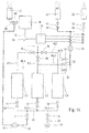
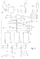
- FIGS. 9 to 15 show a third embodiment of a biogas plant according to the present invention, are provided in the three fermenters 2-1, 2-2 and 2-3 in parallel operation .. Corresponding components are provided with the same reference numerals.
- each of the three fermenters is 2-i with a purge gas inlet 24-1, 24-2 and 24-3 provided, which are each shut off with a valve 10.
- the three purge gas inlets 24-i are combined to form a common purge gas inlet 42.
- In the common purge gas inlet 42 open an exhaust pipe 26 and a fresh air pipe 28, which are each shut off by a valve 10.
- Each of the three fermenters 2-i is provided with a biogas outlet 8-1, 8-2 and 8-3, each of which can be shut off with a valve 10.
- the first biogas / exhaust gas line 14 to the exhaust gas stack 20 and the second biogas / exhaust gas line 16 to the exhaust gas flare 22 are combined to form a common biogas / exhaust gas line 40 in which a blower 38 is arranged.
- the common biogas / waste gas line 40 splits into a first, a second and a third partial biogas / waste gas line 40-1, 40-2 and 40-3.
- the first partial biogas / waste gas line 40-1 opens into the first biogas outlet 8-1 between the valve 10 and the first biofermenter 2-1.
- the second partial biogas / waste gas line 40-2 opens into the second biogas outlet 8-2 between the valve 10 and the second biofermenter 2-2.
- the third partial biogas / waste gas line 40-3 opens into the third biogas outlet 8-3 between the valve 10 and the third biofermenter 2-3.
- the three partial biogas / exhaust gas lines 40-1, 40-2 and 40-3 can each be shut off by a valve 10.
- the three biogas outlets 8-1. 8-2 and 8-3 lead into a common biogas line 12, which leads to a combined heat and power plant 18.
- An exhaust pipe 44 from the CHP 18 opens a second exhaust stack 46.
- the exhaust pipe 26 is connected via a 3-way valve 48 to the exhaust pipe 44, d. H.
- the resulting in the CHP 18 carbon dioxide-containing exhaust gas is used for rinsing a fermenter 2-i to be shut down.
- the 3-way valve By the 3-way valve, the volume flow of the exhaust gas, which is sent to flush a fermenter 2-i via the exhaust pipe 26 and the amount of exhaust gas, which is discharged via the second exhaust stack 46 to the environment, can be controlled.
- a first sensor 32 is arranged to detect the methane concentration in the common biogas line 12.
- a second sensor 34 for detecting the carbon dioxide concentration, a third sensor 36 for Detection of the volume flow and fourth sensor 50 for detecting the methane concentration is arranged in the common biogas / exhaust gas line 40 in the flow direction downstream of the blower 38.
- the four sensors 32, 34, 36 and 50 are connected to a control device 30. Also connected to the control device are the various valves 10. For reasons of clarity, these control lines are not in the FIGS. 9 to 15 located.
- FIGS. 9 to 15 the shutdown and restart of the second fermenter 2-2 is shown, the FIGS. 9 to 15 the same phases and operating conditions as the FIGS. 1 to 7 represent.
- the biogas production of the first and third fermenters 2-1 and 2-3 runs continuously during shutdown and restart of the second fermenter 2-2.
- Fig. 9 shows the first phase of the shutdown of the fermenter 2-2 in the carbon dioxide-containing exhaust gas from the CHP 18 via the 3-way valve 48 and the exhaust pipe 26, the exhaust fan 27 and the second purge gas inlet 24-2 in the interior of the fermenter 2-2 is pumped.
- the second biogas outlet 8-2 is still connected to the common biogas line 12, so that the biogas / waste gas mixture is further supplied to the CHP 18.
- valve 10 in the second biogas outlet 8-2 is closed by the control device 30 and the valve 10 in the second partial biogas / exhaust gas Line 40-2 and in the second biogas / flue line 16 is opened as shown in Fig. 10 is shown.
- the biogas / waste gas mixture in the exhaust gas flare 22 is burned.
- this combustion process may be assisted by the addition of additional fuel.
- the valve 10 in the second biogas / exhaust gas line 16 is closed by the control device 30 and the valve 10 in the first Biogas / exhaust pipe 14 is opened as shown in Fig. 11 is shown.
- the biogas / waste gas mixture is discharged through the exhaust stack 20 to the environment.
- the valve 10 is closed in the exhaust pipe 26 by the controller 30, the 3-way valve 48 is switched accordingly and the valve 10 in the fresh air line 28 is opened as shown in FIG Fig. 12 is shown.
- fresh air is pumped into the fermenter 2-2 via the fresh air line 28 and the purge gas inlet 24 through the fresh air blower 29.
- the exhaust gas / air mixture continues through the second biogas outlet 8-2, the second partial biogas / waste gas line 40-2, the common biogas / waste gas line 40 and the first biogas / waste gas line 14 in the waste gas chimney 20 delivered to the environment.
- this may be assisted by the blower 38.
- the controller 30 opens the valve 10 in the exhaust pipe 26 and switches the 3-way valve 48 in the exhaust pipe 44 of the CHP 18, so the carbon dioxide-containing exhaust gas in the fermenter 2-2 is pumped - see Fig. 14 , This is continued until the detected by the second sensor 34 carbon dioxide concentration in the common biogas / exhaust gas line 40 reaches or exceeds a second threshold.
- the valve 10 in the exhaust gas line 26 is closed by the control device 30, the 3-way valve 38 is switched, the valve 10 in the second partial biogas / exhaust gas line 40-2 is closed and the valve 10 is opened in the second biogas outlet 8-2 as shown in FIG Fig. 15 is shown.
- the second fermenter 2-2 has again reached the phase of biogas production and the biogas produced in the fermenter 2-2 is supplied to the CHP 18 via the biogas line 12.
- the connection of the biogas outlet 8-2 to the common biogas line 12 takes place only when the methane concentration detected by the fourth sensor 50 reaches a fourth limit value. This fourth limit is the same as the upper limit.
- valve 10 in the exhaust pipe 26 may be omitted, since its function can also be taken over by the 3-way valve 48.
- the CHP 18 preferably a gas distribution device (not shown) are connected upstream.
- a gas distribution device By the gas treatment device by means of pressurized water washing, filters or membranes the quality of the biogas raised to the quality level of natural gas, ie in particular the methane content is increased and the carbon dioxide content is reduced.
- Methane concentration upper limit 30% to 50% medium limit 10 to 20% lower limit 0% to 3% fourth limit 30% to 50% Carbon dioxide concentration: first limit 0.5% to 2% second limit 5% to 15%
- the exhaust gas volume flow in the exhaust pipe 26 is between 150 and 1000 m 3 / h.
- the fresh air volume flow in the fresh air line 28 is between 1000 and 5000 m 3 / h.
Landscapes
- Health & Medical Sciences (AREA)
- Chemical & Material Sciences (AREA)
- Life Sciences & Earth Sciences (AREA)
- Engineering & Computer Science (AREA)
- Organic Chemistry (AREA)
- Zoology (AREA)
- Wood Science & Technology (AREA)
- Bioinformatics & Cheminformatics (AREA)
- Genetics & Genomics (AREA)
- Sustainable Development (AREA)
- Biotechnology (AREA)
- Microbiology (AREA)
- Biomedical Technology (AREA)
- Biochemistry (AREA)
- General Engineering & Computer Science (AREA)
- General Health & Medical Sciences (AREA)
- Analytical Chemistry (AREA)
- Molecular Biology (AREA)
- General Chemical & Material Sciences (AREA)
- Oil, Petroleum & Natural Gas (AREA)
- Computer Hardware Design (AREA)
- Clinical Laboratory Science (AREA)
- Processing Of Solid Wastes (AREA)
- Preparation Of Compounds By Using Micro-Organisms (AREA)
- Apparatus Associated With Microorganisms And Enzymes (AREA)
- Treatment Of Sludge (AREA)
Abstract
Description
- Die Erfindung betrifft eine Biogasanlage zur Erzeugung von Biogas aus Biomasse mit wenigstens einem Fermenter nach Anspruch 1 sowie ein Verfahren zum Abschalten eines Fermenters nach Anspruch 10 und ein Verfahren zum Anfahren eines Fermenters nach Anspruch 14.
- Die so genannte "Trockenfermentation" erlaubt es, schüttfähige Biomassen aus der Landwirtschaft, aus Bioabfällen und kommunalen Pflegeflächen zu methanisieren, ohne die Materialien in ein pumpfähiges, flüssiges Substrat zu überführen. Es können Biomassen mit bis zu 50% Trockensubstanzanteil vergoren werden. Dieses Trockenfermentations-Verfahren ist beispielsweise in der
EP 0 934 998 beschrieben. - Bei der "trockenen" Vergärung wird das zu vergärende Material nicht in eine flüssige Phase eingerührt, wie das zum Beispiel bei der Flüssigvergärung von Bioabfällen der Fall ist. Stattdessen wird das in den Fermenter eingebrachte Gärsubstrat ständig feucht gehalten, indem das Perkolat am Fermenterboden abgezogen und über der Biomasse wieder versprüht wird. So werden optimale Lebensbedingungen für die Bakterien erreicht. Bei der Rezirkulation des Perkolats kann zusätzlich die Temperatur reguliert werden, und es besteht die Möglichkeit, Zusatzstoffe für eine Prozessoptimierung zuzugeben.
- Aus der
WO 02/06439 - Das entstehende Biogas kann in einem Blockheizkraftwerk zur Gewinnung von Strom und Wärme genutzt werden. Damit immer genug Biogas für das Blockheizkraftwerk zur Verfügung steht, werden in der Trockenfermentationsanlage mehrere Gärbehälter zeitlich versetzt betrieben. Am Ende der Verweilzeit wird der Fermenterraum vollständig entleert und dann neu befüllt. Das vergorene Substrat wird einer Nachkompostierung zugeführt, so dass ein konventionellen Komposten vergleichbarer organischer Dünger entsteht.
- Bedingt durch den Batch-Betrieb müssen die einzelnen Fermenter von Zeit zu Zeit abgeschaltet werden, d. h. die Biogasproduktion muss gestoppt werden, die vergorene Biomasse muss aus dem jeweiligen Fermenter entnommen und frische Biomasse muss in den Fermenter eingefüllt werden und die Biogasproduktion muss wieder aufgenommen werden. Hierbei muss aus sicherheitstechnischen verhindert werden, dass während des Ent- und Beladens der einzelnen Fermenter ein explosives Biogas/Luft-Gemisch entsteht.
- Hierzu ist es aus der
EP 1 301 583 B1 bekannt, einen laufenden Fermenter im Falle von Explosionsgefahr, d. h. Luft ist in den Fermenter eingedrungen, mit kohlendioxidhaltigem Abgas aus dem mit Biogas betriebenen Blockheizkraftwerk zu fluten. - Es ist daher Aufgabe der vorliegenden Erfindung ausgehend von einer Biogasanlage nach
EP 1 301 583 B das Entladen von verbrauchter Biomasse aus und das Beladen des Fermenters mit frischer Biomasse sicher zu gestalten. - Die Lösung dieser Aufgabe erfolgt durch die Merkmale der Ansprüche 1, 10 und 14.
- Die Biogasanlage nach Anspruch 1 umfasst die notwendigen Komponenten um ein sicheres Abschalten und Entladen und ebenso ein sicheres Anfahren eines Fermenters zu ermöglichen.
- Durch die Maßnahmen nach Anspruch 10 wird die Biogasproduktion und -verwertung auch während des Abschaltens und Spülens mit kohlendioxidhaltigem Abgas solange wie möglich aufrecht erhalten, d. h. das Biogas/Abgas-Gemisch des abzuschaltenden Fermenters wird solange weiter dem Biogasverbraucher zugeführt, bis Qualität diese Gemisches unter einen vorbestimmten Grad absinkt. Erst wenn die Methankonzentration im Biogasauslass unter einen oberen Grenzwert absinkt, wird die zum Biogasverbraucher führende Biogasleitung von dem Biogasauslass getrennt. Danach wird das nur noch wenig Methan enthaltende Biogas/Abgas-Gemisch über einen Abluftkamin abgeführt. Dies erfolgt solange, bis die Methankonzentration auf einen unteren Grenzwert abgesunken ist, bei dem nahezu kein Methan mehr in dem Biogas/Abgas-Gemisch enthalten ist. Danach wird der abzuschaltende Fermenter anstelle mit kohlendioxidhaltigem Abgas mit Frischluft gespült und das Abgas/Biogas/Frischluft-Gemisch wird solange über den Abluftkamin abgeführt, bis die Kohlendioxidkonzentration in dem Abgas/Biogas/Frischluft-Gemisch auf einen ersten Grenzwert abgesunken ist. Erst dann wird der Fermenter geöffnet, um die verbrauchte Biomasse zu entladen und um den Fermenter erneut mit frischer Biomasse zu beladen. Durch die vorausgehenden Spülvorgänge mit Abgas und Frischluft ist das Öffnen und Ent- und Beladen des Fermenters ohne Gefahr für das Bedienungspersonal möglich.
- Gemäß einer bevorzugten Ausgestaltung der Erfindung nach Anspruch 11 wird das Biogas/Abgas-Gemisch bei Erreichen des oberen Grenzwertes der Methankonzentration nicht über den Abluftkamin an die Umwelt abgegeben, sondern einer Abgasfackel zugeführt und dort abgefackelt, Gegebenfalls kann die Abgasfackel mit zusätzlichem Brennstoff versorgt werden, so dass in jedem Fall eine Verbrennung statt findet. Das Abfackeln des Biogas/Abgas-Gemisches erfolgt solange, bis die Methankonzentration in dem Biogas/Abgas-Gemisch einen mittleren Grenzwert unterschreitet, der zwischen dem oberen und dem unteren Grenzwert liegt.
- Gemäß einer bevorzugten Ausgestaltung der Erfindung nach Anspruch 12 wird während des Ent- und Beladens des abgeschalteten Biofermenters über die offene Be- und Entladeöffnung Frischluft angesaugt und das angesaugte Gasgemisch wird über den Spülgaseinlass oder über den Biogasauslass dem Abluftkamin zugeführt. Alternativ kann auch ein spezieller Frischluftabsauganschluss in dem Fermenter vorgesehen werden.
- Durch die vorteilhafte Ausgestaltung der Erfindung nach Anspruch 13 wird sichergestellt, dass während des Ent- und Beladens des Fermenters kontinuierlich Frischluft angesaugt wird
- Durch das erfindungsgemäße Verfahren zum (Wieder-)Anfahren des abgeschalteten Fermenters nach Anspruch 14 und 15 wird sicher verhindert, dass beim Anfahren ein explosives Biogas/Luft-Gemisch entsteht.
- Das Aufschalten dies wieder angefahrenen Fermenters auf die Biogasleitung erfolgt bei einem vierten Grenzwert der Methankonzentration, der gleich dem oberen Grenzwert ist - Anspruch 16.
- Das Abgas zur Spülung des abzuschaltenden Fermenters wird beispielsweise von einer Verbrennungskraftmaschine bereit gestellt - Anspruch 17.
- Gemäß einer bevorzugten Ausführungsform der Erfindung nach Anspruch 18 wird das kohlendioxidhaltige Abgas aus einer dem wenigstens einen Fermenter nach geschalteten Biogasaufbereitungseinrichtung bereitgestellt.
- Die übrigen Unteransprüche beziehen sich auf vorteilhafte Ausgestaltungen der Erfindung.
- Weitere Einzelheiten, Merkmale und Vorteile der Erfindung zeigt die nachfolgende Beschreibung beispielhafter Ausführungsformen anhand der Zeichnungen:
- Es zeigt:
-
Fig. 1 bis 7 schematische Darstellungen verschiedener Betriebszustände während des Abschaltens und während des (Wieder-) Anfahrens eines Fermenters; -
Fig. 8 eine schematische Darstellung einer zweiten Ausführungsform der Erfindung mit einem Fermenter; und -
Fig. 9 bis 15 schematische Darstellungen verschiedener Betriebszustände einer Biogasanlage mit drei Fermentern während des Abschaltens und während des (Wieder-) Anfahrens eines Fermenters
-
- Die
Figuren 1 bis 7 zeigen eine erste Ausführungsform einer Biogasanlage gemäß der vorliegenden Erfindung mit einem einzelnen Fermenter 2. Der Fermenter 2 ist quaderförmig und besitzt in etwa den Aufbau einer Fertiggarage. Über eine Be- und Entladeöffnung 4, die sich über eine der Stirnseiten des quaderförmigen Fermenters 2 erstreckt, lässt sich Biomasse 6 mittels eines Radladers in den Fermenter 2 einfüllen und wieder entnehmen. Hinsichtlich des genauen Aufbaus des Fermenters 2 wird auf dieWO 02/06439 - Der Fermenter 2 umfasst weiter einen Biogasauslass 8, der über Ventile 10 mit einer Biogasleitung 12, einer ersten Biogas/Abgas-Leitung 14 und einer zweiten Biogas/Abgas-Leitung 16 verbindbar sind. Die Biogasleitung 12 führt zu einem Blockheizkraftwerk 18 als Biogasverwertungseinrichtung. Die erste Biogas/Abgas-Leitung 14 führt zu einem Abgaskamin 20. Die zweite Biogas/Abgas-Leitung 16 führt zu eine Abgasfackel 22, Weiter umfasst der Fermenter 2 einen Spülgaseinlass 24, der über Ventile 10 mit einer Abgasleitung 26 oder einer Frischluftleitung 28 verbindbar ist. In der Abgasleitung 26 ist ein Abgasgebläse 27 angeordnet, mittels dem Abgas in den Fermenter 2 gepumpt werden kann. In der Frischluftleitung 28 ist ein Frischluftgebläse 29 zum Ansaugen von Frischluft aus der Umgebung angeordnet. Über die Abgasleitung 26 wird kohlendioxidhaltiges Abgas als Spülgas und über die Frischluftleitung 28 wird Frischluft in den Fermenter 2 geführt.
- Die Ventile 10 sind mit einer Steuereinrichtung 30 verbunden und werden durch die Steuereinrichtung 30 geöffnet oder geschlossen. Die Steuereinrichtung 30 ist auch mit einem ersten Messfühler 32 verbunden, der im Biogasauslass 8 angeordnet ist und die Methankonzentration in dem jeweiligen Gasgemisch erfasst. Die Steuereinrichtung 30 ist weiter mit einem zweiten Messfühler 34 verbunden, der ebenfalls im Biogasauslass 8 angeordnet ist und die Kohlendioxidkonzentration in dem jeweiligen Gasgemisch erfasst. Die Steuereinrichtung 30 ist auch mit einem dritten Messfühler 36 verbunden, der im Biogasauslass 8 angeordnet ist und den Gasvolumenstrom in dem Biogasauslass erfasst. Über ein in dem Biogasauslass angeordnetes Gebläse 38 kann der Abzug von Gas aus dem Fermenter 2 gegebenenfalls unterstützt werden.
- In den
Figuren 1 bis 7 sind verschieden Phasen des Abschaltens und Anfahrens des Fermenters 2 dargestellt, wobei aktive Leitungen und Stellungen von Komponenten durchgezogen dargestellt sind, während nichtaktive bzw. abgesperrte Leitungen und Stellungen von Komponenten strichliert dargestellt sind. -
Fig. 1 zeigt die erste Phase des Abschaltens des Fermenters 2 bei der kohlendioxidhaltiges Abgas über die Abgasleitung 26 und den Spülgaseinlass 24 in das Innere des Fermenters 2 gepumpt wird. Der Biogasauslass 8 ist nach wie vor mit der Biogasleitung 12 verbunden, so dass das Biogas/Abgas-Gemisch weiter dem BHKW 18 zugeführt wird. - Erst wenn die durch den ersten Messfühler 32 in dem Biogasauslass 8 erfasste Methankonzentration unter einen oberen Grenzwert abgesunken ist, wird das Ventil 10 in der Biogasleitung 12 durch die Steuereinrichtung 30 geschlossen und das Ventil 10 in der zweiten Biogas/Abgas-Leitung 16 wird geöffnet, wie dies in
Fig. 2 dargestellt ist. In dieser zweiten Phase des Abschaltens des Fermenters 2 wird das Biogas/Abgas-Gemisch in der Abgasfackel 22 verbrannt. Gegebenenfalls kann dieser Verbrennungsprozess durch Zugabe von zusätzlichem Brennstoff unterstützt werden. - Wenn die durch den ersten Messfühler 32 in dem Biogasauslass 8 erfasste Methankonzentration unter einen mittleren Grenzwert abgesunken ist, wird das Ventil 10 in der zweiten Biogas/Abgas-Leitung 16 durch die Steuereinrichtung 30 geschlossen und das Ventil 10 in der ersten Biogas/Abgas-Leitung 14 wird geöffnet, wie dies in
Fig. 3 dargestellt ist. In dieser dritten Phase des Abschaltens des Fermenters 2 wird das Biogas/Abgas-Gemisch über den Abgaskamin 20 an die Umgebung abgegeben. - Wenn die durch den ersten Messfühler 32 in dem Biogasauslass 8 erfasste Methankonzentration unter einen unteren Grenzwert abgesunken ist, wird das Ventil 10 in der Abgasleitung 26 durch die Steuereinrichtung 30 geschlossen und das Ventil 10 in der Frischluftleitung 28 wird geöffnet, wie dies in
Fig. 4 dargestellt ist. In dieser vierten Phase des Abschaltens des Fermenters 2 wird über die Frischluftleitung 28 und den Spülgaseinlass 24 Frischluft in den Fermenter 2 gepumpt. Das Abgas/Luft-Gemisch wird weiter über den Biogasauslass 8 und die erste Biogas/Abgas-Leitung 14 in dem Abgaskamin 20 an die Umgebung abgegeben. - Wenn die durch den zweiten Messfühler 34 in dem Biogasauslass 8 erfasste Kohlendioxidkonzentration unter einen ersten Grenzwert abgesunken ist, wird das Ventil 10 in der Frischluftleitung 28 durch die Steuereinrichtung 30 geschlossen und die Be- und Entladeöffnung 4 geöffnet, wie dies in
Fig. 5 dargestellt ist. Gleichzeitig wird über das Gebläse 38 Frischluft über die offene Be- und Entladeöffnung angesaugt und über den Abgaskamin 20 an die Umgebung abgegeben. Auf diese Weise wird verhindert, dass noch in der vergorenen Biomasse enthaltene Biogasreste während des Entladens eine Gefahr für das Bedienungspersonal darstellen. - Ist der Fermenter 2 wieder mit frischer Biomasse beladen, wird die Be- und Entladeöffnung 4 geschlossen, die Verbindung zwischen Biogasauslass 8 und Abgaskamin 20 über die erste Biogas/Abgas-Leitung 14 wird aufrecht erhalten und die Steuereinrichtung 30 öffnet das Ventil 10 in der Abgasleitung 26, so das kohlendioxidhaltiges Abgas in den Fermenter 2 gepumpt wird - siehe
Fig. 6 . Dies wird solange fortgesetzt, bis die durch den zweiten Messfühler 34 erfasste Kohlendioxidkonzentration in dem Biogasauslass 8 einen zweiten Grenzwert erreicht bzw. übersteigt. - Ist dieser zweite Grenzwert für die Kohlendioxidkonzentration erreicht, wird durch die Steuereinrichtung 30 das Ventil 10 in der Abgasleitung 26 und in der ersten Biogas/Abgas-Leitung 14 geschlossen und das Ventil 10 in der Biogasleitung 12 geöffnet, wie dies in
Fig. 7 dargestellt ist. Damit ist die Phase der Biogasproduktion wieder erreicht und das in dem Fermenter 2 erzeugte Biogas wird über die Biogasleitung 12 dem BHKW 18 zugeführt. - Bei der vorstehend beschriebenen Ausführungsform sind alle Messfühler 32, 34, 36 in dem Biogasauslass 8 angeordnet. Alternativ können der zweite und dritte Messfühler 24, 36 auch in der ersten bzw. zweiten Biogas/Abgas-Leitung 14, 16 angeordnet werden.
Fig. 8 zeigt eine alternative Ausgestaltung der Erfindung, die sich von der Ausführungsform nach denFig. 1 bis 7 dadurch unterscheidet, dass die erste und zweite Biogas/Abgas-Leitung 14, 16 zu einer gemeinsamen Biogas/Abgas-Leitung 40 zusammengefasst sind, bevor sie in den Biogasauslass 8 münden, Der zweite. Messfühler zur Erfassung der Kohlendioxidkonzentration ist in der gemeinsamen Biogas/Abgas-Leitung 40 angeordnet und der dritte Messfühler 36 ist in der ersten Biogas/Abgas-Leitung 14 angeordnet. Im übrigen stimmt diese zweite Ausführungsform der Erfindung mit der ersten Ausführungsform überein. Auch die Funktionsweise ist identisch. - Die
Figuren 9 bis 15 zeigen eine dritte Ausführungsform einer Biogasanlage gemäß der vorliegenden Erfindung, bei der drei Fermenter 2-1, 2-2 und 2-3 im Parallelbetrieb vorgesehen sind.. Einander entsprechende Komponenten sind mit den gleichen Bezugszeichen versehen. Bei der Biogasanlage nach denFiguren 9 bis 15 ist jeder der drei Fermenter 2-i mit einem Spülgaseinlass 24-1, 24-2 und 24-3 versehen, die jeweils mit einem Ventil 10 absperrbar sind. Die drei Spülgaseinlässe 24-i sind zu einem gemeinsamen Spülgaseinlass 42 zusammengefasst. In den gemeinsamen Spülgaseinlass 42 münden eine Abgasleitung 26 und eine Frischtuftleitung 28, die jeweils durch ein Ventil 10 absperrbar sind. - Jeder der drei Fermenter 2-i ist mit einem Biogasauslass 8-1, 8-2 und 8-3 versehen, der jeweils mit einem Ventil 10 absperrbar sind. Die erste Biogas/Abgas-Leitung 14 zu dem Abgaskamin 20 und die zweite Biogas/Abgas-Leitung 16 zu der Abgasfackel 22 sind zu einer gemeinsamen Biogas/Abgas-Leitung 40 zusammengefasst in der ein Gebläse 38 angeordnet ist. Nach dem Gebläse 38 spaltet sich die gemeinsame Biogas/Abgas-Leitung 40 auf in eine erste, eine zweite und eine dritte Teil-Biogas/Abgas-Leitung 40-1, 40-2 und 40-3. Die erste Teil-Biogas/Abgas-Leitung 40-1 mündet zwischen Ventil 10 und dem ersten Biofermenter 2-1 in den ersten Biogasauslass 8-1. Die zweite Teil-Biogas/Abgas-Leitung 40-2 mündet zwischen Ventil 10 und dem zweiten Biofermenter 2-2 in den zweiten Biogasauslass 8-2. Die dritte Teil-Biogas/Abgas-Leitung 40-3 mündet zwischen Ventil 10 und dem dritten Biofermenter 2-3 in den dritten Biogasauslass 8-3. Die drei Teil-Biogas/Abgas-Leitungen 40-1, 40-2 und 40-3 sind jeweils durch ein Ventil 10 absperrbar. Die drei Biogasauslässe 8-1. 8-2 und 8-3 münden in eine gemeinsame Biogasleitung 12, die zu einem Blockheizkraftwerk 18 führt. Eine Auspuffleitung 44 aus dem BHKW 18 mündet einen zweiten Abgaskamin 46. Die Abgasleitung 26 ist über ein 3-Wege-Ventil 48 mit der Auspuffleitung 44 verbunden, d. h. das in dem BHKW 18 anfallende kohlendioxidhaltige Abgas wird zum Spülen eines abzuschaltenden Fermenters 2-i verwendet. Durch das 3-Wege-Ventil kann der Volumenstrom des Abgases, der zum Spülen eines Fermenters 2-i über die Abgasleitung 26 geschickt wird und die Menge des Abgases, die über den zweiten Abgaskamin 46 an die Umgebung abgegeben wird, geregelt werden.
- Ein erster Messfühler 32 ist zur Erfassung der Methankonzentration in der gemeinsamen Biogasleitung 12 angeordnet. Ein zweiter Messfühler 34 zur Erfassung der Kohlendioxidkonzentration, ein dritter Messfühler 36 zur Erfassung des Volumenstroms und vierter Messfühler 50 zur Erfassung der Methankonzentration ist in der gemeinsamen Biogas/Abgas-Leitung 40 in Strömungsrichtung nach dem Gebläse 38 angeordnet. Die vier Messfühler 32, 34, 36 und 50 sind mit einer Steuereinrichtung 30 verbunden. Ebenfalls mit der Steuereinrichtung verbunden sind die verschiedenen Ventile 10. Aus Gründen der Übersichtlichkeit sind diese Steuerleitungen nicht in den
Figuren 9 bis 15 eingezeichnet. - In den
Figuren 9 bis 15 wird das Abschalten und wieder Anfahren des zweiten Fermenters 2-2 dargestellt, wobei dieFiguren 9 bis 15 die gleichen Phasen und Betriebszustände wie dieFiguren 1 bis 7 darstellen. Die Biogasproduktion des ersten und dritten Fermenters 2-1 und 2-3 läuft während des Abschaltens und wieder Anfahrens des zweiten Fermenters 2-2 kontinuierlich durch. -
Fig. 9 zeigt die erste Phase des Abschaltens des Fermenters 2-2 bei der kohlendioxidhaltiges Abgas aus dem BHKW 18 über das 3-Wege-Ventil 48 und die Abgasleitung 26, das Abgasgebläse 27 und den zweiten Spülgaseinlass 24-2 in das Innere des Fermenters 2-2 gepumpt wird. Der zweite Biogasauslass 8-2 ist nach wie vor mit der gemeinsamen Biogasleitung 12 verbunden, so dass das Biogas/Abgas-Gemisch weiter dem BHKW 18 zugeführt wird. - Erst wenn die durch den ersten Messfühler 32 in der gemeinsamen Biogasleitung 12 erfasste Methankonzentration unter einen oberen Grenzwert abgesunken ist, wird das Ventil 10 im zweiten Biogasauslass 8-2 durch die Steuereinrichtung 30 geschlossen und das Ventil 10 in der zweiten Teil-Biogas/Abgas-Leitung 40-2 und in der zweiten Biogas/Abgas-Leitung 16 wird geöffnet, wie dies in
Fig. 10 dargestellt ist. In dieser zweiten Phase des Abschaltens des Fermenters 2-2 wird das Biogas/Abgas-Gemisch in der Abgasfackel 22 verbrannt. Gegebenenfalls kann dieser Verbrennungsprozess durch Zugabe von zusätzlichem Brennstoff unterstützt werden. - Wenn die durch den vierten Messfühler 50 in der gemeinsamen Biogas/Abgas-Leitung 40 erfasste Methankonzentration unter einen mittleren Grenzwert abgesunken ist, wird das Ventil 10 in der zweiten Biogas/Abgas-Leitung 16 durch die Steuereinrichtung 30 geschlossen und das Ventil 10 in der ersten Biogas/Abgas-Leitung 14 wird geöffnet, wie dies in
Fig. 11 dargestellt ist. In dieser dritten Phase des Abschaltens des Fermenters 2-2 wird das Biogas/Abgas-Gemisch über den Abgaskamin 20 an die Umgebung abgegeben. - Wenn die durch den vierten Messfühler 50 in der gemeinsamen Biogas/Abgas-Leitung 40 erfasste Methankonzentration unter einen unteren Grenzwert abgesunken ist, wird das Ventil 10 in der Abgasleitung 26 durch die Steuereinrichtung 30 geschlossen, das 3-Wege-Ventil 48 wird entsprechend geschaltet und das Ventil 10 in der Frischluftleitung 28 wird geöffnet, wie dies in
Fig. 12 dargestellt ist. In dieser vierten Phase des Abschaltens des Fermenters 2-2 wird über die Frischluftleitung 28 und den Spülgaseinlass 24 durch das Frischluftgebläse 29 Frischluft, in den Fermenter 2-2 gepumpt. Das Abgas/Luft-Gemisch wird weiter über den zweiten Biogasauslass 8-2, die zweite Teil-Biogas/Abgas-Leitung 40-2, die gemeinsame Biogas/Abgas-Leitung 40 und die erste Biogas/Abgas-Leitung 14 in dem Abgaskamin 20 an die Umgebung abgegeben. Gegebenenfalls kann dies durch das Gebläse 38 unterstützt werden. - Wenn die durch den zweiten Messfühler 34 in der gemeinsamen Biogasleitung 40 erfasste Kohlendioxidkonzentration unter einen ersten Grenzwert abgesunken ist, wird das Ventil 10 in der Frischluftleitung 28 durch die Steuereinrichtung 30 geschlossen und das Frischluftgebläse 29 abgeschaltet, wie dies in
Fig. 13 dargestellt ist. Die in denFiguren 9 bis 15 nicht dargestellte Be- und Entladeöffnung wird geöffnet. Gleichzeitig wird über das Gebläse 38 in die gemeinsamen Biogas/Abgas-Leitung 40 Frischluft über die offene Be- und Entladeöffnung angesaugt und über den Abgaskamin 20 an die Umgebung abgegeben. Auf diese Weise wird verhindert, dass noch in der vergorenen Biomasse enthaltene Biogasreste während des Entladens eine Gefahr für das Bedienungspersonal darstellen. Auch Abgase eines zum Be- und Entladen verwendeten Radladers werden damit abgesaugt. - Ist der Fermenter 2-2 wieder mit frischer Biomasse beladen, wird die Be- und Entladeöffnung geschlossen, die Verbindung zwischen zweiten Biogasauslass 8-2 und Abgaskamin 20 über die zweite Teil-Biogas/Abgas-Leitung 40-2, die gemeinsame Biogas/Abgas-Leitung und die erste Biogas/Abgas-Leitung 14 wird aufrecht erhalten und die Steuereinrichtung 30 öffnet das Ventil 10 in der Abgasleitung 26 und schaltet das 3-Wege-Ventil 48 in der Auspuffleitung 44 des BHKW 18, so das kohlendioxidhaltiges Abgas in den Fermenter 2-2 gepumpt wird - siehe
Fig. 14 . Dies wird solange fortgesetzt, bis die durch den zweiten Messfühler 34 erfasste Kohlendioxidkonzentration in der gemeinsamen Biogas/Abgas-Leitung 40 einen zweiten Grenzwert erreicht bzw. übersteigt. - Ist dieser zweite Grenzwert für die Kohlendioxidkonzentration erreicht, wird durch die Steuereinrichtung 30 das Ventil 10 in der Abgasleitung 26 geschlossen, das 3-Wege-Ventil 38 geschalten, das Ventil 10 in der zweiten Teil-Biogas/Abgas-Leitung 40-2 wird geschlossen und das Ventil 10 in dem zweiten Biogasauslass 8-2 geöffnet, wie dies in
Fig. 15 dargestellt ist. Damit hat auch der zweite Fermenter 2-2 wieder die Phase der Biogasproduktion erreicht und das in dem Fermenter 2-2 erzeugte Biogas wird über die Biogasleitung 12 dem BHKW 18 zugeführt. Die Zuschaltung des Biogasauslasses 8-2 zu der gemeinsamen Biogasleitung 12 erfolgt erst dann, wenn die durch den vierten Messfühler 50 erfasste Methankonzentration einen vierten Grenzwert erreicht. Dieser vierte Grenzwert stimmt mit dem oberen Grenzwert überein. - Das Ventil 10 in der Abgasleitung 26 kann entfallen, da dessen Funktion auch durch das 3-Wege-Ventil 48 übernommen werden kann.
- Statt die Biogasleitung 12 direkt mit dem BHKW 18 zu verbinden, kann dem BHKW 18 vorzugsweise eine Gasaufbreitungseinrichtung (nicht dargestellt) vorgeschaltet werden. Durch die Gasaufbereitungseinrichtung wird mittels Druckwasserwäsche, Filtern oder Membranen die Qualität des erzeugten Biogases auf die Qualitätsstufe von Erdgas angehoben, d. h. es wird insbesondere der Methananteil erhöht und der Kohlendioxidanteil wird verringert.
- Nachfolgend sind beispielhafte Zahlenwerte für die verschiedenen Grenzwerte angegeben:
Methankonzentration: oberer Grenzwert 30% bis 50% mittlerer Grenzwert 10% bis 20% unterer Grenzwert 0% bis 3% vierter Grenzwert 30% bis 50% Kohlendioxidkonzentration: erster Grenzwert 0,5% bis 2% zweiter Grenzwert 5% bis 15% -
- 2
- Fermenter
- 4
- Be- und Entladeöffnung
- 6
- Biomasse
- 8
- Biogasauslass
- 10
- Ventile
- 12
- Biogasleitung
- 14
- erste Biogas/Abgas-Leitung
- 16
- zweite Biogas/Abgas-Leitung
- 18
- Blockheizkraftwerk
- 20
- Abgaskamin
- 22
- Abgasfackel
- 24
- Spülgaseinlass
- 26
- Abgasleitung
- 27
- Abgasgebläse
- 28
- Frischluftleitung
- 29
- Frischluftgebläse
- 30
- Steuereinrichtung
- 32
- erster Messfühler (Methankonzentration)
- 34
- zweiter Messfühler (Kohlendioxidkonzentration)
- 36
- dritter Messfühler (Volumenstrom)
- 38
- Gebläse
- 40
- gemeinsame Biogas/Abgas-Leitung
- 40-1
- erste Teil-Biogas/Abgas-Leitung
- 40-2
- zweite Teil-Biogas/Abgas-Leitung
- 40-3
- dritte Teil-Biogas/Abgas-Leitung
- 42
- gemeinsamer Spülgaseinlass
- 44
- Auspuffleitung
- 46
- zweiter Abgaskamin
- 48
- 3-Wege-Ventil
- 50
- vierter Messfühler (Methankonzentration)
Claims (19)
- Biogasanlage zur Erzeugung von Biogas mit
wenigstens einem nach dem Prinzip der Trockenfermentation arbeitenden Fermenter (2) zur Erzeugung von Biogas im Batch-Betrieb mit einem Biogasauslass (8) und einem Spülgaseinlass (24);
einer Biogasleitung (12) die mit dem Biogasauslass (8) verbindbar ist;
einer Abgasleitung (26) mittels der kohlendioxidhaltiges Abgas dem Spülgaseinlass (24) zuführbar ist;
einem Abgaskamin (20), der über eine erste Biogas/Abgas-Leitung (14) mit dem Biogasauslass (8) verbindbar ist;
einer Abgasfackel (22), die über eine zweite Biogas/Abgas-Leitung (16) mit dem Biogasauslass (8) verbindbar ist;
einer Frischluftleitung (28), die mit dem Spülgaseinlass (24) verbindbar ist;
einer Steuereinrichtung (30) zur Verbindung des Biogasauslasses (8) mit der Biogasleitung (12) oder mit dem Bioabgaskamin (20) über die erste Biogas/Abgas-Leitung (14) oder mit der Abgasfackel (22) über die zweite Biogas/Abgas-Leitung (16) und zur Verbindung des Spülgaseinlasses (24) mit der Abgasleitung (26) oder mit der Frischluftleitung (28); und
einer Messeinrichtung (32, 34), die mit der Steuereinrichtung (30) verbunden ist und einen ersten Messfühler (32) zur Erfassung der Methankonzentration und einen zweiten Messfühler (34) zur Erfassung der Kohlendioxidkonzentration in dem aus dem wenigstens einen Fermenter (2) austretenden Gasgemisch umfasst. - Biogasanlage nach Anspruch 1, dadurch gekennzeichnet, dass die Messeinrichtung (32, 34) in dem Biogasauslass (8) angeordnet ist.
- Biogasanlage nach Anspruch 1 oder 2, dadurch gekennzeichnet, dass eine Mehrzahl von Fermentern (2-i) vorgesehen sind, deren Biogasauslässe (8-i) in die gemeinsamen Biogasleitung (12) münden und dass der erste Messfühler zur Erfassung der Methankonzentration in der gemeinsamen Biogasleitung angeordnet ist.
- Biogasanlage nach Anspruch 3, dadurch gekennzeichnet, dass die Biogasauslässe (8-i) selektiv über eine gemeinsame Biogas/Abgas-Leitung (40) mit dem Abgaskamin (20) oder der Abgasfackel (22) verbindbar sind und dass der zweite Messfühler zur Erfassung der Kohlendioxidkonzentration in der gemeinsamen Biogas/Abgas-Leitung angeordnet ist.
- Biogasanlage nach einem der vorhergehenden Ansprüche, dadurch gekennzeichnet, dass die Abgasleitung (26) Abgas aus einer Verbrennungskraftmaschine zuführt.
- Biogasanlage nach einem der vorhergehenden Ansprüche, dadurch gekennzeichnet, dass die Biogasleitung (12) die Verbindung zu einer Biogasverwertungseinrichtung herstellt, die kohlendioxidhaltiges Abgas erzeugt.
- Biogasanlage nach Anspruch 5, dadurch gekennzeichnet, dass die Biogasverwertungseinrichtung ein Blockheizkraftwerk (18) umfasst.
- Biogasanlage nach Anspruch 5, dadurch gekennzeichnet, dass die Biogasverwertungseinrichtung eine Brennstoffzelle umfasst.
- Biogasanlage nach Anspruch 5, dadurch gekennzeichnet, dass die Biogasverwertungseinrichtung eine Gasaufbereitungseinrichtung (44) umfasst.
- Verfahren zum Abschalten eines Fermenters in einer Biogasanlage nach einem der vorhergehenden Ansprüche mit den Verfahrensschritten:a) Beibehalten der Verbindung zwischen Biogasauslass (8) und Biogasleitung (12);b) Verbinden der Abgasleitung (26) mit dem Spülgaseinlass (24) des abzuschaltenden Fermenters (2);c) Spülen des abzuschaltenden Fermenters (2) mit Abgas aus der Abgasleitung (26) bis die durch den ersten Messfühler (32) erfasste Methankonzentration auf einen oberen Grenzwert abgesunken ist;d) Trennen der Biogasleitung (12) von dem Biogasauslass (8) des abzuschaltenden Fermenters (2);e) Verbinden des Biogasauslasses (8) des abzuschaltenden Fermenters (2) mit der ersten Biogas/Abgas-Leitung (14) und Zufuhr des Abgas/Biogas-Gemisches zu dem Bioabgaskamin (20) bis die durch den ersten Messfühler (32) erfasste Methankonzentration auf einen unteren Grenzwert abgesunken ist;f) Trennen der Abgasleitung (26) von dem Spülgaseinlass (24) des abzuschaltenden Fermenters (2);g) Verbinden der Frischluftleitung (28) mit dem Spülgaseinlass (24) des abzuschaltenden Fermenters (2) und Zufuhr von Frischluft in den abzuschaltenden Fermenter (2) bis die durch den zweiten Messfühler (34) erfasste Kohlendioxidkonzentration auf einen ersten Grenzwert abgesunken ist; undh) Öffnen der Be- und Entladeöffnung (4) des abgeschalteten Fermenters (2).
- Verfahren nach Anspruch 10, dadurch gekennzeichnet, dass zwischen dem Verfahrensschritt d) und dem Verfahrensschritt e) folgende Verfahrensschritte ausgeführt werden:d1) Verbinden des Biogasauslasses (8) des abzuschaltenden Fermenters (2) mit der zweiten Biogas/Abgas-Leitung (16) und Zufuhr des Abgas/Biogas-Gemisches zu der Abgasfackel (22) bis die durch den ersten Messfühler (32) erfasste Methankonzentration auf einen mittleren Grenzwert abgesunken ist, der zwischen dem oberen und dem unteren Grenzwert liegt; undd2) Trennen des Biogasauslasses (8) des abzuschaltenden Fermenters (2) von der zweiten Biogas/Abgas-Leitung (16).
- Verfahren nach Anspruch 10 oder 11, weiter gekennzeichnet durch die Verfahrensschritte:i) Verbinden der Frischluftleitung (28) mit dem Spülgaseinlass (24) und/oder dem Biogasauslass (8); undj) Zufuhr von Frischluft in den abgeschalteten Fermenter (2) über die Be- und Entladeöffnung (4) durch Absaugen über den Spülgaseinlass (24) und/oder den Biogasauslass (8) während des Ent- und Beladens des abgeschalteten Fermenters (2).
- Verfahren nach Anspruch 12, dadurch gekennzeichnet, dass während des Verfahrensschrittes j) der Mengenstrom des über den Spülgaseinlass (24) und/oder den Biogasauslass (8) abgesaugten Luft/Biogas/Abgas-Gemisches durch die Steuereinrichtung (30) überwacht wird .
- Verfahren zum Anfahren eines frisch mit Biomasse beladenen Fermenters (2) nach einem der vorhergehenden Ansprüche 1 bis 9 mit den Verfahrensschritten:a) Schließen der Be- und Entladeöffnung (4);b) Verbinden des Biogasauslasses (8) mit der ersten Biogas/Abgas-Leitung (14);c) Verbinden der Abgasleitung (26) mit dem Spülgaseinlass (24) des anzufahrenden Fermenters (2) und Zufuhr von Abgas zu dem anzufahrenden Fermenter (2) bis die durch den zweiten Messfühler (34) erfasste Kohlendioxidkonzentration einen zweiten Grenzwertwert erreicht;d) Trennen der Abgasleitung (26) von dem Spülgaseinlass (24);e) Trennen der ersten Biogas/Abgas-Leitung (14) von dem Biogasauslass (8);f) Verbinden der Biogasleitung (12) mit dem Biogasauslass (8).
- Verfahren nach Anspruch 14, dadurch gekennzeichnet, dass der Verfahrensschritt f) ausgeführt wird, wenn die durch den ersten oder vierten Messfühler (32; 50) erfasste Methankonzentration einen vierten Grenzwert überschreitet.
- Verfahren nach Anspruch 15, dadurch gekennzeichnet, dass der vierte Grenzwert der Methankonzentration gleich dem oberen Grenzwert der Methankonzentration ist.
- Verfahren nach einem der vorhergehenden Ansprüche 10 bis 16, dadurch gekennzeichnet, dass die Abgasleitung (26) mit dem Auspuff einer Verbrennungskraftmaschine verbunden wird.
- Verfahren nach einem der vorhergehenden Ansprüche 10 bis 16, dadurch gekennzeichnet, dass die Abgasleitung (26) mit dem Auspuff einer kohlendioxidhaltiges Abgas erzeugenden Biogasaufbereitungsseinrichtung verbunden ist.
- Verfahren nach einem der vorhergehenden Ansprüche 10 bis 16, dadurch gekennzeichnet, dass die Abgasleitung (26) mit dem Auspuff einer Brennstoffzelle verbunden ist.
Priority Applications (1)
| Application Number | Priority Date | Filing Date | Title |
|---|---|---|---|
| PL08156915T PL1997875T5 (pl) | 2007-05-29 | 2008-05-26 | Instalacja biogazu do wytwarzania biogazu z biomasy i sposób eksploatacji instalacji biogazu |
Applications Claiming Priority (1)
| Application Number | Priority Date | Filing Date | Title |
|---|---|---|---|
| DE102007024911A DE102007024911B4 (de) | 2007-05-29 | 2007-05-29 | Biogasanlage zur Erzeugung von Biogas aus Biomasse sowie Verfahren zum Betreiben der Biogasanlage |
Publications (3)
| Publication Number | Publication Date |
|---|---|
| EP1997875A1 true EP1997875A1 (de) | 2008-12-03 |
| EP1997875B1 EP1997875B1 (de) | 2010-08-04 |
| EP1997875B2 EP1997875B2 (de) | 2017-01-25 |
Family
ID=39739539
Family Applications (1)
| Application Number | Title | Priority Date | Filing Date |
|---|---|---|---|
| EP08156915.4A Active EP1997875B2 (de) | 2007-05-29 | 2008-05-26 | Biogasanlage zur Erzeugung von Biogas aus Biomasse sowie Verfahren zum Betreiben der Biogasanlage |
Country Status (10)
| Country | Link |
|---|---|
| US (2) | US8187869B2 (de) |
| EP (1) | EP1997875B2 (de) |
| JP (1) | JP5250305B2 (de) |
| CN (1) | CN101314756B (de) |
| AT (1) | ATE476493T1 (de) |
| BR (1) | BRPI0802137A2 (de) |
| DE (2) | DE102007024911B4 (de) |
| EA (1) | EA013985B1 (de) |
| ES (1) | ES2350326T5 (de) |
| PL (1) | PL1997875T5 (de) |
Cited By (14)
| Publication number | Priority date | Publication date | Assignee | Title |
|---|---|---|---|---|
| EP2103681A2 (de) | 2008-03-20 | 2009-09-23 | Bekon Energy Technologies GmbH & Co.Kg | Kombinierte Anlage zur Erzeugung von Biogas und Kompost sowie Verfahren zum Umschalten eines Fermenters in einer solchen Anlage zwischen Biogaserzeugung und Kompostierung |
| EP2251408A1 (de) | 2009-05-11 | 2010-11-17 | KOMPOFERM GmbH | Verfahren und Vorrichtung zum Betreiben einer Fermentationsanlage |
| DE102009050867A1 (de) * | 2009-10-27 | 2011-04-28 | Vsr Industrietechnik Gmbh | Verfahren zur Erzeugung von Biogas durch Trockenfermentation sowie Biogasanlage zur Gewinnung von Biogas durch Trockenfermentation |
| US8105823B2 (en) | 2007-05-29 | 2012-01-31 | Bekon Energy Technologies Gmbh & Co., Kg | Biogas installation for production of biogas from biomass, and methods for operation of the biogas installation |
| WO2012079735A2 (de) | 2010-12-15 | 2012-06-21 | Bioferm Gmbh | Verfahren und anlage zur methanisierung von biomasse |
| US8272436B2 (en) | 2008-12-01 | 2012-09-25 | Bekon Energy Technologies Gmbh & Co. Kg | Reducing methane slack when starting and stopping biogas fermenters |
| DE102012108893A1 (de) * | 2012-09-20 | 2014-03-20 | Renergon International AG | Verfahren zum Betrieb einer Biogasanlage sowie Biogasanlage |
| WO2014060423A1 (de) * | 2012-10-15 | 2014-04-24 | Renergon International AG | Verfahren und vorrichtung zur erzeugung von biogas |
| CN103911278A (zh) * | 2014-04-24 | 2014-07-09 | 承德昊远塑料制品有限公司 | 一种组合式沼气生物发酵制备系统 |
| EP2826850A1 (de) * | 2013-07-18 | 2015-01-21 | Peter Lutz | Biogasanlage zur Erzeugung von Biogas aus nicht-pumpbarer Biomasse sowie Verfahren zu ihrem Betrieb |
| US9034621B2 (en) | 2010-11-17 | 2015-05-19 | Zerowaste Energy, Llc | Method and device for operating a fermentation plant |
| CN110425552A (zh) * | 2019-08-26 | 2019-11-08 | 武汉环投环境科技有限公司 | 低浓沼气防爆进入火炬燃烧的装置及其燃烧除臭方法 |
| ES2787799A1 (es) * | 2019-04-15 | 2020-10-16 | Moayad Mohammad Abushokhedim | Sistema de fermentacion acelerada |
| CN112798346A (zh) * | 2020-12-30 | 2021-05-14 | 农业部沼气科学研究所 | 一种沼气发酵批次试验气液共取样的实验方法及系统 |
Families Citing this family (13)
| Publication number | Priority date | Publication date | Assignee | Title |
|---|---|---|---|---|
| DE102009053143A1 (de) * | 2009-11-05 | 2011-05-12 | Gke Consult Beratende Ingenieure Gmbh | Verfahren und Vorrichtung zur Behandlung von Gärresten |
| DE102010017818A1 (de) | 2010-02-17 | 2011-08-18 | Meissner, Jan A. | Verfahren und Anlage zur Herstellung von CBM (Compressed BioMethane) als treibhausgasfreier Kraftstoff |
| WO2011112736A2 (en) * | 2010-03-09 | 2011-09-15 | Enos Loy Stover | Optimized biogas (biomethane) production from anaerobic reactors |
| JP5587028B2 (ja) * | 2010-05-12 | 2014-09-10 | 本田技研工業株式会社 | リグノセルロース系バイオマス糖化前処理装置 |
| CA2850249A1 (en) * | 2011-09-29 | 2013-04-04 | Kompoferm Gmbh | Biogas plant and method for operating a biogas plant |
| DE202012100816U1 (de) | 2012-03-07 | 2013-07-03 | Bekon Energy Technologies Gmbh & Co. Kg | Bioreaktor zur Methanisierung von Biomasse und eine Biogasanlage mit einer Mehrzahl von solchen Bioreaktoren |
| EP2823031B1 (de) | 2012-03-06 | 2018-04-11 | BEKON GmbH | Bioreaktor zur methanisierung von biomasse sowie ein verfahren zum betreiben eines solchen bioreaktors |
| ITBO20120164A1 (it) * | 2012-03-27 | 2013-09-28 | Ambientalia S R L | Unita' di digestione per rifiuti organici ed impianto di trattamento di rifiuti organici comprendente detta unita'. |
| US9090497B2 (en) | 2012-05-31 | 2015-07-28 | Jeffrey H. Bragg | Modular, scalable high solids methane digester for small-sized to medium-sized farms |
| ITMI20122114A1 (it) * | 2012-12-11 | 2014-06-12 | Dentro Il Sole S P A | Biosmoke |
| CA2844897A1 (en) * | 2013-03-15 | 2014-09-15 | Bpc Acquisition Company | Cng dispenser |
| CN105605601B (zh) * | 2016-03-11 | 2017-10-31 | 宜都市桥河食品有限公司 | 蒸汽锅炉用沼气‑天然气混合用气系统 |
| BE1028840B1 (nl) * | 2020-11-30 | 2022-06-27 | Krivalec Bvba | Inrichting en werkwijze voor productie van elektriciteit en warmte door verwerking van biomassa |
Citations (4)
| Publication number | Priority date | Publication date | Assignee | Title |
|---|---|---|---|---|
| EP0934998A2 (de) | 1998-02-09 | 1999-08-11 | Manfred Prof. Dr. Hoffmann | Verfahren und Vorrichtung zur Methanisierung von Biomassen |
| WO2002006439A2 (de) | 2000-07-14 | 2002-01-24 | Bekon Energy Technologies Gmbh | Bioreaktor zur methanisierung von biomasse und eine biogasanlage zur erzeugung von thermischer, elektrischer oder mechanischer energie aus biomasse mit einem solchen bioreaktor sowie verfahren zur regelung und steuerung einer solchen biogasanlage |
| DE20319847U1 (de) * | 2003-12-23 | 2005-05-04 | Lutz, Peter | Großfermenter zur Erzeugung von Biogas aus Biomasse und eine Biogasanlage zur Erzeugung von thermischer, elektrischer und/oder mechanischer Energie aus Biogas mit einem solchen Großfermenter |
| EP1681274A2 (de) * | 2005-01-17 | 2006-07-19 | Orgaworld B.V. | Verfahren und Vorrichtung zur Durchführung eines Fermentationsprozesses in einem Reaktor |
Family Cites Families (15)
| Publication number | Priority date | Publication date | Assignee | Title |
|---|---|---|---|---|
| DE3438057A1 (de) | 1984-10-17 | 1986-04-17 | Johannes Dipl.-Ing. 6200 Wiesbaden Linneborn | Verfahren zur aufbereitung von biomassen |
| SU1748693A1 (ru) | 1989-12-26 | 1992-07-23 | Харьковский Институт Механизации И Электрификации Сельского Хозяйства | Установка дл переработки органических отходов животноводства и растениеводства в биогаз и продукты дл получени удобрений |
| FR2672583B1 (fr) * | 1991-02-11 | 1993-04-23 | Degremont | Procede de regulation d'un dispositif de depollution d'eaux residuaires. |
| JP3147491B2 (ja) * | 1992-06-03 | 2001-03-19 | 栗田工業株式会社 | 有機酸濃度の測定方法及びメタン発酵処理装置 |
| DE19719323A1 (de) | 1997-05-08 | 1998-11-12 | Rudolf Dipl Ing Loock | Tunnelfermentationsverfahren zur einstufigen anaeroben und aeroben Behandlung von festen und flüssigen biogenen Abfällen |
| WO2001065621A1 (en) * | 2000-03-02 | 2001-09-07 | Ebara Corporation | Fuel cell power generation method and system |
| JP4149766B2 (ja) | 2002-04-12 | 2008-09-17 | レーベン ラリー | 生分解性有機材料を産生ガスに転換するための方法及び装置 |
| RU2254700C1 (ru) | 2003-12-29 | 2005-06-27 | Научно-технический центр по разработке технологий и оборудования (НТЦ РТО) | Биогазовая установка анаэробного сбраживания органических отходов |
| US7414149B2 (en) * | 2004-11-22 | 2008-08-19 | Rohm And Haas Company | Non-routine reactor shutdown method |
| US7906304B2 (en) * | 2005-04-05 | 2011-03-15 | Geosynfuels, Llc | Method and bioreactor for producing synfuel from carbonaceous material |
| US7481940B2 (en) * | 2005-08-18 | 2009-01-27 | Newbio E-Systems, Incorporated | Biomass treatment of organic waste or water waste |
| EP1762607A1 (de) | 2005-09-07 | 2007-03-14 | U.T.S. Umwelt-Technik-Süd GmbH | Biogasanlagen-Regelungsverfahren |
| JP2007082438A (ja) * | 2005-09-21 | 2007-04-05 | Ebara Corp | 微生物による有価物生産方法および有価物生産装置 |
| DE102007024911B4 (de) * | 2007-05-29 | 2009-04-09 | Bekon Energy Technologies Gmbh & Co. Kg | Biogasanlage zur Erzeugung von Biogas aus Biomasse sowie Verfahren zum Betreiben der Biogasanlage |
| DE102008015240B4 (de) * | 2008-03-20 | 2010-05-20 | Bekon Energy Technologies Gmbh & Co. Kg | Kombinierte Anlage zur Erzeugung von Biogas und Kompost sowie Verfahren zum Umschalten eines Fermenters in einer solchen Anlage zwischen Biogaserzeugung und Kompostierung |
-
2007
- 2007-05-29 DE DE102007024911A patent/DE102007024911B4/de active Active
-
2008
- 2008-05-22 JP JP2008133753A patent/JP5250305B2/ja active Active
- 2008-05-23 US US12/126,708 patent/US8187869B2/en active Active
- 2008-05-26 AT AT08156915T patent/ATE476493T1/de active
- 2008-05-26 EP EP08156915.4A patent/EP1997875B2/de active Active
- 2008-05-26 ES ES08156915.4T patent/ES2350326T5/es active Active
- 2008-05-26 PL PL08156915T patent/PL1997875T5/pl unknown
- 2008-05-26 DE DE502008001061T patent/DE502008001061D1/de active Active
- 2008-05-28 EA EA200801217A patent/EA013985B1/ru not_active IP Right Cessation
- 2008-05-29 BR BRPI0802137-6A patent/BRPI0802137A2/pt not_active IP Right Cessation
- 2008-05-29 CN CN2008100999496A patent/CN101314756B/zh active Active
-
2010
- 2010-08-18 US US12/859,093 patent/US8105823B2/en active Active
Patent Citations (5)
| Publication number | Priority date | Publication date | Assignee | Title |
|---|---|---|---|---|
| EP0934998A2 (de) | 1998-02-09 | 1999-08-11 | Manfred Prof. Dr. Hoffmann | Verfahren und Vorrichtung zur Methanisierung von Biomassen |
| WO2002006439A2 (de) | 2000-07-14 | 2002-01-24 | Bekon Energy Technologies Gmbh | Bioreaktor zur methanisierung von biomasse und eine biogasanlage zur erzeugung von thermischer, elektrischer oder mechanischer energie aus biomasse mit einem solchen bioreaktor sowie verfahren zur regelung und steuerung einer solchen biogasanlage |
| EP1301583B1 (de) | 2000-07-14 | 2004-10-06 | Bekon Energy Technologies GmbH | Bioreaktor zur methanisierung von biomasse und eine biogasanlage zur erzeugung von thermischer, elektrischer oder mechanischer energie aus biomasse mit einem solchen bioreaktor sowie verfahren zur regelung und steuerung einer solchen biogasanlage |
| DE20319847U1 (de) * | 2003-12-23 | 2005-05-04 | Lutz, Peter | Großfermenter zur Erzeugung von Biogas aus Biomasse und eine Biogasanlage zur Erzeugung von thermischer, elektrischer und/oder mechanischer Energie aus Biogas mit einem solchen Großfermenter |
| EP1681274A2 (de) * | 2005-01-17 | 2006-07-19 | Orgaworld B.V. | Verfahren und Vorrichtung zur Durchführung eines Fermentationsprozesses in einem Reaktor |
Cited By (28)
| Publication number | Priority date | Publication date | Assignee | Title |
|---|---|---|---|---|
| US8105823B2 (en) | 2007-05-29 | 2012-01-31 | Bekon Energy Technologies Gmbh & Co., Kg | Biogas installation for production of biogas from biomass, and methods for operation of the biogas installation |
| US8187869B2 (en) | 2007-05-29 | 2012-05-29 | Bekon Energy Technologies Gmbh & Co., Kg | Biogas installation for production of biogas from biomass, and methods for operation of the biogas installation |
| US8440437B2 (en) | 2008-03-20 | 2013-05-14 | Bekon Energy Technologies Gmbh & Co., Kg | Combined installation for the production of biogas and compost, and method of switching a fermenter in a like installation between biogas production and composting |
| EP2103681A2 (de) | 2008-03-20 | 2009-09-23 | Bekon Energy Technologies GmbH & Co.Kg | Kombinierte Anlage zur Erzeugung von Biogas und Kompost sowie Verfahren zum Umschalten eines Fermenters in einer solchen Anlage zwischen Biogaserzeugung und Kompostierung |
| EP2103681A3 (de) * | 2008-03-20 | 2010-06-30 | Bekon Energy Technologies GmbH & Co.Kg | Kombinierte Anlage zur Erzeugung von Biogas und Kompost sowie Verfahren zum Umschalten eines Fermenters in einer solchen Anlage zwischen Biogaserzeugung und Kompostierung |
| DE102008015240B4 (de) * | 2008-03-20 | 2010-05-20 | Bekon Energy Technologies Gmbh & Co. Kg | Kombinierte Anlage zur Erzeugung von Biogas und Kompost sowie Verfahren zum Umschalten eines Fermenters in einer solchen Anlage zwischen Biogaserzeugung und Kompostierung |
| DE102008015240A1 (de) * | 2008-03-20 | 2009-09-24 | Bekon Energy Technologies Gmbh & Co. Kg | Kombinierte Anlage zur Erzeugung von Biogas und Kompost sowie Verfahren zum Umschalten eines Fermenters in einer solchen Anlage zwischen Biogaserzeugung und Kompostierung |
| US8272436B2 (en) | 2008-12-01 | 2012-09-25 | Bekon Energy Technologies Gmbh & Co. Kg | Reducing methane slack when starting and stopping biogas fermenters |
| US8408293B2 (en) | 2008-12-01 | 2013-04-02 | Bekon Energy Technologies Gmbh & Co. Kg | Reducing methane slack when starting and stopping biogas fermenters |
| EP2374867A1 (de) | 2009-05-11 | 2011-10-12 | KOMPOFERM GmbH | Verfahren und Vorrichtung zum Betreiben einer Fermentationsanlage |
| EP2251408A1 (de) | 2009-05-11 | 2010-11-17 | KOMPOFERM GmbH | Verfahren und Vorrichtung zum Betreiben einer Fermentationsanlage |
| DE102009050867A1 (de) * | 2009-10-27 | 2011-04-28 | Vsr Industrietechnik Gmbh | Verfahren zur Erzeugung von Biogas durch Trockenfermentation sowie Biogasanlage zur Gewinnung von Biogas durch Trockenfermentation |
| US9234215B2 (en) | 2010-11-17 | 2016-01-12 | Zerowaste Energy, Llc | Method and device for operating a fermentation plant |
| US9034621B2 (en) | 2010-11-17 | 2015-05-19 | Zerowaste Energy, Llc | Method and device for operating a fermentation plant |
| WO2012079735A3 (de) * | 2010-12-15 | 2012-08-30 | Bioferm Gmbh | Verfahren und anlage zur methanisierung von biomasse |
| DE102010054676A1 (de) | 2010-12-15 | 2012-06-21 | Bioferm Gmbh | Verfahren und Anlage zur Methanisierung von Biomasse |
| WO2012079735A2 (de) | 2010-12-15 | 2012-06-21 | Bioferm Gmbh | Verfahren und anlage zur methanisierung von biomasse |
| DE102012108893A1 (de) * | 2012-09-20 | 2014-03-20 | Renergon International AG | Verfahren zum Betrieb einer Biogasanlage sowie Biogasanlage |
| WO2014060423A1 (de) * | 2012-10-15 | 2014-04-24 | Renergon International AG | Verfahren und vorrichtung zur erzeugung von biogas |
| DE102013107683A1 (de) * | 2013-07-18 | 2015-01-22 | Peter Lutz | Biogasanlage zur Erzeugung von Biogas aus nicht-pumpbarer Biomasse sowie Verfahren zu ihrem Betrieb |
| EP2826850A1 (de) * | 2013-07-18 | 2015-01-21 | Peter Lutz | Biogasanlage zur Erzeugung von Biogas aus nicht-pumpbarer Biomasse sowie Verfahren zu ihrem Betrieb |
| DE102013107683B4 (de) * | 2013-07-18 | 2017-10-12 | Peter Lutz | Biogasanlage zur Erzeugung von Biogas aus nicht-pumpbarer Biomasse sowie Verfahren zu ihrem Betrieb |
| CN103911278A (zh) * | 2014-04-24 | 2014-07-09 | 承德昊远塑料制品有限公司 | 一种组合式沼气生物发酵制备系统 |
| ES2787799A1 (es) * | 2019-04-15 | 2020-10-16 | Moayad Mohammad Abushokhedim | Sistema de fermentacion acelerada |
| CN110425552A (zh) * | 2019-08-26 | 2019-11-08 | 武汉环投环境科技有限公司 | 低浓沼气防爆进入火炬燃烧的装置及其燃烧除臭方法 |
| CN110425552B (zh) * | 2019-08-26 | 2024-03-15 | 武汉环投环境科技有限公司 | 低浓沼气防爆进入火炬燃烧的装置及其燃烧除臭方法 |
| CN112798346A (zh) * | 2020-12-30 | 2021-05-14 | 农业部沼气科学研究所 | 一种沼气发酵批次试验气液共取样的实验方法及系统 |
| CN112798346B (zh) * | 2020-12-30 | 2024-01-26 | 农业部沼气科学研究所 | 一种沼气发酵批次试验气液共取样的实验方法及系统 |
Also Published As
| Publication number | Publication date |
|---|---|
| PL1997875T5 (pl) | 2018-08-31 |
| EA200801217A1 (ru) | 2008-12-30 |
| JP5250305B2 (ja) | 2013-07-31 |
| EA013985B1 (ru) | 2010-08-30 |
| EP1997875B1 (de) | 2010-08-04 |
| ATE476493T1 (de) | 2010-08-15 |
| US8187869B2 (en) | 2012-05-29 |
| US20080299634A1 (en) | 2008-12-04 |
| US8105823B2 (en) | 2012-01-31 |
| DE502008001061D1 (de) | 2010-09-16 |
| JP2009022271A (ja) | 2009-02-05 |
| PL1997875T3 (pl) | 2011-02-28 |
| CN101314756A (zh) | 2008-12-03 |
| CN101314756B (zh) | 2013-04-17 |
| ES2350326T5 (es) | 2017-06-22 |
| US20100311141A1 (en) | 2010-12-09 |
| ES2350326T3 (es) | 2011-01-21 |
| EP1997875B2 (de) | 2017-01-25 |
| DE102007024911A1 (de) | 2009-01-02 |
| DE102007024911B4 (de) | 2009-04-09 |
| BRPI0802137A2 (pt) | 2009-12-08 |
Similar Documents
| Publication | Publication Date | Title |
|---|---|---|
| EP1997875B1 (de) | Biogasanlage zur Erzeugung von Biogas aus Biomasse sowie Verfahren zum Betreiben der Biogasanlage | |
| DE102008015240B4 (de) | Kombinierte Anlage zur Erzeugung von Biogas und Kompost sowie Verfahren zum Umschalten eines Fermenters in einer solchen Anlage zwischen Biogaserzeugung und Kompostierung | |
| EP2370562A2 (de) | Verfahren zur verminderung von methanschlupf beim anfahren und abschalten von biogasfermentern sowie biogasanlage zur durchführung dieses verfahrens | |
| EP1428868B1 (de) | Vorrichtung zur anaeroben Fermentation von Biomasse | |
| EP2566946B1 (de) | Verfahren und anlage zur gasdichten prozessführung von perkolatoren in einem zwei- oder mehrstufigen biogasverfahren | |
| WO2011026964A2 (de) | Verfahren und vorrichtung zur behandlung fermentierbarer substanzen | |
| DE102017010229A1 (de) | Pfropfenstrom-Fermenter einer Biogasanlage | |
| EP2597144A1 (de) | Vorrichtung zur Fermentation organischer Feststoffe | |
| CN106399079A (zh) | 干式厌氧系统 | |
| CN108467170A (zh) | 发酵罐以及包含其的协同处理城市生活垃圾和市政污泥的干式厌氧发酵系统及方法 | |
| EP1692256B1 (de) | Grossfermenter zur erzeugung von biogas aus biomasse | |
| DE102006044353A1 (de) | Trockenfermenter | |
| DE102007025903A1 (de) | Vorrichtung und Verfahren zur Erzeugung von Biogas durch kontinuierliche Trockenfermentierung stapelbarer Biomasse | |
| DE102006009652A1 (de) | Anlage und Verfahren zur Biogaserzeugung mit wenigstens einem Trockenfermenter und mindestens einem damit verbundenen Perkolataufbereiter | |
| DE20319847U1 (de) | Großfermenter zur Erzeugung von Biogas aus Biomasse und eine Biogasanlage zur Erzeugung von thermischer, elektrischer und/oder mechanischer Energie aus Biogas mit einem solchen Großfermenter | |
| DE102009032122A1 (de) | Verfahren und Vorrichtung zur Energiegewinnung aus Biomasse und Biogasanlage | |
| CN205917273U (zh) | 干式厌氧系统 | |
| EP1589095A1 (de) | Vorrichtung zur Erzeugung und Verwertung von Biogas | |
| DE20318783U1 (de) | Großfermenter zur Erzeugung von Biogas aus Biomasse und eine Biogasanlage zur Erzeugung von thermischer, elektrischer und/oder mechanischer Energie aus Biogas mit einem solchen Großfermenter |
Legal Events
| Date | Code | Title | Description |
|---|---|---|---|
| PUAI | Public reference made under article 153(3) epc to a published international application that has entered the european phase |
Free format text: ORIGINAL CODE: 0009012 |
|
| AK | Designated contracting states |
Kind code of ref document: A1 Designated state(s): AT BE BG CH CY CZ DE DK EE ES FI FR GB GR HR HU IE IS IT LI LT LU LV MC MT NL NO PL PT RO SE SI SK TR |
|
| AX | Request for extension of the european patent |
Extension state: AL BA MK RS |
|
| 17P | Request for examination filed |
Effective date: 20090528 |
|
| AKX | Designation fees paid |
Designated state(s): AT BE BG CH CY CZ DE DK EE ES FI FR GB GR HR HU IE IS IT LI LT LU LV MC MT NL NO PL PT RO SE SI SK TR |
|
| GRAP | Despatch of communication of intention to grant a patent |
Free format text: ORIGINAL CODE: EPIDOSNIGR1 |
|
| GRAS | Grant fee paid |
Free format text: ORIGINAL CODE: EPIDOSNIGR3 |
|
| GRAA | (expected) grant |
Free format text: ORIGINAL CODE: 0009210 |
|
| AK | Designated contracting states |
Kind code of ref document: B1 Designated state(s): AT BE BG CH CY CZ DE DK EE ES FI FR GB GR HR HU IE IS IT LI LT LU LV MC MT NL NO PL PT RO SE SI SK TR |
|
| REG | Reference to a national code |
Ref country code: GB Ref legal event code: FG4D Free format text: NOT ENGLISH |
|
| REG | Reference to a national code |
Ref country code: CH Ref legal event code: EP |
|
| REG | Reference to a national code |
Ref country code: IE Ref legal event code: FG4D Free format text: LANGUAGE OF EP DOCUMENT: GERMAN |
|
| REF | Corresponds to: |
Ref document number: 502008001061 Country of ref document: DE Date of ref document: 20100916 Kind code of ref document: P |
|
| REG | Reference to a national code |
Ref country code: CH Ref legal event code: NV Representative=s name: ISLER & PEDRAZZINI AG |
|
| REG | Reference to a national code |
Ref country code: SE Ref legal event code: TRGR |
|
| REG | Reference to a national code |
Ref country code: NL Ref legal event code: T3 |
|
| REG | Reference to a national code |
Ref country code: ES Ref legal event code: FG2A Effective date: 20110111 |
|
| PG25 | Lapsed in a contracting state [announced via postgrant information from national office to epo] |
Ref country code: NO Free format text: LAPSE BECAUSE OF FAILURE TO SUBMIT A TRANSLATION OF THE DESCRIPTION OR TO PAY THE FEE WITHIN THE PRESCRIBED TIME-LIMIT Effective date: 20101104 Ref country code: FI Free format text: LAPSE BECAUSE OF FAILURE TO SUBMIT A TRANSLATION OF THE DESCRIPTION OR TO PAY THE FEE WITHIN THE PRESCRIBED TIME-LIMIT Effective date: 20100804 |
|
| PG25 | Lapsed in a contracting state [announced via postgrant information from national office to epo] |
Ref country code: HR Free format text: LAPSE BECAUSE OF FAILURE TO SUBMIT A TRANSLATION OF THE DESCRIPTION OR TO PAY THE FEE WITHIN THE PRESCRIBED TIME-LIMIT Effective date: 20100804 Ref country code: CY Free format text: LAPSE BECAUSE OF FAILURE TO SUBMIT A TRANSLATION OF THE DESCRIPTION OR TO PAY THE FEE WITHIN THE PRESCRIBED TIME-LIMIT Effective date: 20100804 Ref country code: SI Free format text: LAPSE BECAUSE OF FAILURE TO SUBMIT A TRANSLATION OF THE DESCRIPTION OR TO PAY THE FEE WITHIN THE PRESCRIBED TIME-LIMIT Effective date: 20100804 Ref country code: BG Free format text: LAPSE BECAUSE OF FAILURE TO SUBMIT A TRANSLATION OF THE DESCRIPTION OR TO PAY THE FEE WITHIN THE PRESCRIBED TIME-LIMIT Effective date: 20101104 Ref country code: IS Free format text: LAPSE BECAUSE OF FAILURE TO SUBMIT A TRANSLATION OF THE DESCRIPTION OR TO PAY THE FEE WITHIN THE PRESCRIBED TIME-LIMIT Effective date: 20101204 |
|
| REG | Reference to a national code |
Ref country code: PL Ref legal event code: T3 |
|
| PG25 | Lapsed in a contracting state [announced via postgrant information from national office to epo] |
Ref country code: GR Free format text: LAPSE BECAUSE OF FAILURE TO SUBMIT A TRANSLATION OF THE DESCRIPTION OR TO PAY THE FEE WITHIN THE PRESCRIBED TIME-LIMIT Effective date: 20101105 |
|
| PG25 | Lapsed in a contracting state [announced via postgrant information from national office to epo] |
Ref country code: DK Free format text: LAPSE BECAUSE OF FAILURE TO SUBMIT A TRANSLATION OF THE DESCRIPTION OR TO PAY THE FEE WITHIN THE PRESCRIBED TIME-LIMIT Effective date: 20100804 |
|
| PLBI | Opposition filed |
Free format text: ORIGINAL CODE: 0009260 |
|
| PG25 | Lapsed in a contracting state [announced via postgrant information from national office to epo] |
Ref country code: SK Free format text: LAPSE BECAUSE OF FAILURE TO SUBMIT A TRANSLATION OF THE DESCRIPTION OR TO PAY THE FEE WITHIN THE PRESCRIBED TIME-LIMIT Effective date: 20100804 Ref country code: RO Free format text: LAPSE BECAUSE OF FAILURE TO SUBMIT A TRANSLATION OF THE DESCRIPTION OR TO PAY THE FEE WITHIN THE PRESCRIBED TIME-LIMIT Effective date: 20100804 Ref country code: CZ Free format text: LAPSE BECAUSE OF FAILURE TO SUBMIT A TRANSLATION OF THE DESCRIPTION OR TO PAY THE FEE WITHIN THE PRESCRIBED TIME-LIMIT Effective date: 20100804 |
|
| PLAX | Notice of opposition and request to file observation + time limit sent |
Free format text: ORIGINAL CODE: EPIDOSNOBS2 |
|
| 26 | Opposition filed |
Opponent name: BIOFERM GMBH Effective date: 20110504 Opponent name: KOMPOFERM GMBH Effective date: 20110504 |
|
| PLAF | Information modified related to communication of a notice of opposition and request to file observations + time limit |
Free format text: ORIGINAL CODE: EPIDOSCOBS2 |
|
| REG | Reference to a national code |
Ref country code: DE Ref legal event code: R026 Ref document number: 502008001061 Country of ref document: DE Effective date: 20110504 |
|
| PLAF | Information modified related to communication of a notice of opposition and request to file observations + time limit |
Free format text: ORIGINAL CODE: EPIDOSCOBS2 |
|
| PG25 | Lapsed in a contracting state [announced via postgrant information from national office to epo] |
Ref country code: MC Free format text: LAPSE BECAUSE OF NON-PAYMENT OF DUE FEES Effective date: 20110531 Ref country code: MT Free format text: LAPSE BECAUSE OF FAILURE TO SUBMIT A TRANSLATION OF THE DESCRIPTION OR TO PAY THE FEE WITHIN THE PRESCRIBED TIME-LIMIT Effective date: 20100804 |
|
| PLBB | Reply of patent proprietor to notice(s) of opposition received |
Free format text: ORIGINAL CODE: EPIDOSNOBS3 |
|
| PG25 | Lapsed in a contracting state [announced via postgrant information from national office to epo] |
Ref country code: LU Free format text: LAPSE BECAUSE OF NON-PAYMENT OF DUE FEES Effective date: 20110526 |
|
| PG25 | Lapsed in a contracting state [announced via postgrant information from national office to epo] |
Ref country code: PT Free format text: LAPSE BECAUSE OF NON-PAYMENT OF DUE FEES Effective date: 20100804 |
|
| PGFP | Annual fee paid to national office [announced via postgrant information from national office to epo] |
Ref country code: SE Payment date: 20130521 Year of fee payment: 6 Ref country code: EE Payment date: 20130523 Year of fee payment: 6 Ref country code: IE Payment date: 20130521 Year of fee payment: 6 Ref country code: LT Payment date: 20130522 Year of fee payment: 6 |
|
| PGFP | Annual fee paid to national office [announced via postgrant information from national office to epo] |
Ref country code: BE Payment date: 20130521 Year of fee payment: 6 Ref country code: LV Payment date: 20130523 Year of fee payment: 6 Ref country code: NL Payment date: 20130523 Year of fee payment: 6 |
|
| PG25 | Lapsed in a contracting state [announced via postgrant information from national office to epo] |
Ref country code: HU Free format text: LAPSE BECAUSE OF FAILURE TO SUBMIT A TRANSLATION OF THE DESCRIPTION OR TO PAY THE FEE WITHIN THE PRESCRIBED TIME-LIMIT Effective date: 20100804 |
|
| REG | Reference to a national code |
Ref country code: NL Ref legal event code: V1 Effective date: 20141201 |
|
| REG | Reference to a national code |
Ref country code: LT Ref legal event code: MM4D Effective date: 20140526 |
|
| REG | Reference to a national code |
Ref country code: EE Ref legal event code: MM4A Ref document number: E004933 Country of ref document: EE Effective date: 20140531 |
|
| PG25 | Lapsed in a contracting state [announced via postgrant information from national office to epo] |
Ref country code: EE Free format text: LAPSE BECAUSE OF NON-PAYMENT OF DUE FEES Effective date: 20140531 Ref country code: SE Free format text: LAPSE BECAUSE OF NON-PAYMENT OF DUE FEES Effective date: 20140527 Ref country code: LT Free format text: LAPSE BECAUSE OF NON-PAYMENT OF DUE FEES Effective date: 20140526 |
|
| REG | Reference to a national code |
Ref country code: SE Ref legal event code: EUG |
|
| REG | Reference to a national code |
Ref country code: IE Ref legal event code: MM4A |
|
| PG25 | Lapsed in a contracting state [announced via postgrant information from national office to epo] |
Ref country code: LV Free format text: LAPSE BECAUSE OF NON-PAYMENT OF DUE FEES Effective date: 20140526 Ref country code: NL Free format text: LAPSE BECAUSE OF NON-PAYMENT OF DUE FEES Effective date: 20141201 |
|
| PG25 | Lapsed in a contracting state [announced via postgrant information from national office to epo] |
Ref country code: IE Free format text: LAPSE BECAUSE OF NON-PAYMENT OF DUE FEES Effective date: 20140526 |
|
| REG | Reference to a national code |
Ref country code: FR Ref legal event code: PLFP Year of fee payment: 8 |
|
| PLBP | Opposition withdrawn |
Free format text: ORIGINAL CODE: 0009264 |
|
| REG | Reference to a national code |
Ref country code: FR Ref legal event code: PLFP Year of fee payment: 9 |
|
| REG | Reference to a national code |
Ref country code: DE Ref legal event code: R082 Ref document number: 502008001061 Country of ref document: DE Representative=s name: THIELKING & ELBERTZHAGEN PATENTANWAELTE, DE Ref country code: DE Ref legal event code: R082 Ref document number: 502008001061 Country of ref document: DE Representative=s name: THIELKING & ELBERTZHAGEN PATENTANWAELTE PARTNE, DE |
|
| REG | Reference to a national code |
Ref country code: DE Ref legal event code: R082 Ref document number: 502008001061 Country of ref document: DE Representative=s name: THIELKING & ELBERTZHAGEN PATENTANWAELTE, DE Ref country code: DE Ref legal event code: R082 Ref document number: 502008001061 Country of ref document: DE Representative=s name: THIELKING & ELBERTZHAGEN PATENTANWAELTE PARTNE, DE Ref country code: DE Ref legal event code: R081 Ref document number: 502008001061 Country of ref document: DE Owner name: BEKON GMBH, DE Free format text: FORMER OWNER: BEKON ENERGY TECHNOLOGIES GMBH & CO. KG, 85774 UNTERFOEHRING, DE |
|
| PUAH | Patent maintained in amended form |
Free format text: ORIGINAL CODE: 0009272 |
|
| STAA | Information on the status of an ep patent application or granted ep patent |
Free format text: STATUS: PATENT MAINTAINED AS AMENDED |
|
| 27A | Patent maintained in amended form |
Effective date: 20170125 |
|
| AK | Designated contracting states |
Kind code of ref document: B2 Designated state(s): AT BE BG CH CY CZ DE DK EE ES FI FR GB GR HR HU IE IS IT LI LT LU LV MC MT NL NO PL PT RO SE SI SK TR |
|
| REG | Reference to a national code |
Ref country code: DE Ref legal event code: R102 Ref document number: 502008001061 Country of ref document: DE |
|
| REG | Reference to a national code |
Ref country code: CH Ref legal event code: AELC Ref country code: CH Ref legal event code: PCOW Free format text: NEW ADDRESS: MAX-PLANCK-STRASSE 15, 33428 MARIENFELD (DE) Ref country code: CH Ref legal event code: PFA Owner name: BEKON GMBH, DE Free format text: FORMER OWNER: BEKON HOLDING AG, DE Ref country code: CH Ref legal event code: PFUS Owner name: BEKON HOLDING AG, DE Free format text: FORMER OWNER: BEKON ENERGY TECHNOLOGIES GMBH AND CO. KG, DE |
|
| REG | Reference to a national code |
Ref country code: FR Ref legal event code: PLFP Year of fee payment: 10 |
|
| REG | Reference to a national code |
Ref country code: GB Ref legal event code: 732E Free format text: REGISTERED BETWEEN 20170406 AND 20170412 |
|
| REG | Reference to a national code |
Ref country code: ES Ref legal event code: DC2A Ref document number: 2350326 Country of ref document: ES Kind code of ref document: T5 Effective date: 20170622 |
|
| REG | Reference to a national code |
Ref country code: AT Ref legal event code: PC Ref document number: 476493 Country of ref document: AT Kind code of ref document: T Owner name: BEKON GMBH, DE Effective date: 20170519 |
|
| REG | Reference to a national code |
Ref country code: FR Ref legal event code: CA Effective date: 20170626 Ref country code: FR Ref legal event code: CD Owner name: BEKON GMBH, DE Effective date: 20170626 Ref country code: FR Ref legal event code: TP Owner name: BEKON GMBH, DE Effective date: 20170622 |
|
| PG25 | Lapsed in a contracting state [announced via postgrant information from national office to epo] |
Ref country code: BE Free format text: LAPSE BECAUSE OF NON-PAYMENT OF DUE FEES Effective date: 20140531 |
|
| REG | Reference to a national code |
Ref country code: ES Ref legal event code: PC2A Owner name: BEKON GMBH Effective date: 20171030 |
|
| REG | Reference to a national code |
Ref country code: FR Ref legal event code: PLFP Year of fee payment: 11 |
|
| P01 | Opt-out of the competence of the unified patent court (upc) registered |
Effective date: 20230606 |
|
| PGFP | Annual fee paid to national office [announced via postgrant information from national office to epo] |
Ref country code: IT Payment date: 20230531 Year of fee payment: 16 |
|
| PGFP | Annual fee paid to national office [announced via postgrant information from national office to epo] |
Ref country code: GB Payment date: 20240522 Year of fee payment: 17 |
|
| PGFP | Annual fee paid to national office [announced via postgrant information from national office to epo] |
Ref country code: DE Payment date: 20240524 Year of fee payment: 17 |
|
| PGFP | Annual fee paid to national office [announced via postgrant information from national office to epo] |
Ref country code: CH Payment date: 20240602 Year of fee payment: 17 |
|
| PGFP | Annual fee paid to national office [announced via postgrant information from national office to epo] |
Ref country code: ES Payment date: 20240614 Year of fee payment: 17 |
|
| PGFP | Annual fee paid to national office [announced via postgrant information from national office to epo] |
Ref country code: AT Payment date: 20240517 Year of fee payment: 17 |
|
| PGFP | Annual fee paid to national office [announced via postgrant information from national office to epo] |
Ref country code: FR Payment date: 20240522 Year of fee payment: 17 |
|
| PGFP | Annual fee paid to national office [announced via postgrant information from national office to epo] |
Ref country code: PL Payment date: 20240508 Year of fee payment: 17 |
|
| PGFP | Annual fee paid to national office [announced via postgrant information from national office to epo] |
Ref country code: TR Payment date: 20240515 Year of fee payment: 17 |