EP1997757B1 - Changeur de rouleaux avec un cône de serrage pour le support d'un tube avec un rouleau de matériau enroulé - Google Patents
Changeur de rouleaux avec un cône de serrage pour le support d'un tube avec un rouleau de matériau enroulé Download PDFInfo
- Publication number
- EP1997757B1 EP1997757B1 EP08151344A EP08151344A EP1997757B1 EP 1997757 B1 EP1997757 B1 EP 1997757B1 EP 08151344 A EP08151344 A EP 08151344A EP 08151344 A EP08151344 A EP 08151344A EP 1997757 B1 EP1997757 B1 EP 1997757B1
- Authority
- EP
- European Patent Office
- Prior art keywords
- cone
- changer according
- reel changer
- clamping jaws
- clamping
- Prior art date
- Legal status (The legal status is an assumption and is not a legal conclusion. Google has not performed a legal analysis and makes no representation as to the accuracy of the status listed.)
- Active
Links
- 239000000463 material Substances 0.000 title claims description 22
- 238000006073 displacement reaction Methods 0.000 claims description 4
- 210000003746 feather Anatomy 0.000 claims description 4
- 239000003999 initiator Substances 0.000 claims description 3
- 230000005540 biological transmission Effects 0.000 description 4
- 238000000034 method Methods 0.000 description 4
- 238000004804 winding Methods 0.000 description 4
- 238000005553 drilling Methods 0.000 description 3
- 238000010276 construction Methods 0.000 description 2
- 229910000639 Spring steel Inorganic materials 0.000 description 1
- 229910000831 Steel Inorganic materials 0.000 description 1
- 238000006243 chemical reaction Methods 0.000 description 1
- 230000006835 compression Effects 0.000 description 1
- 238000007906 compression Methods 0.000 description 1
- 239000004519 grease Substances 0.000 description 1
- 238000005461 lubrication Methods 0.000 description 1
- 238000004519 manufacturing process Methods 0.000 description 1
- 239000002184 metal Substances 0.000 description 1
- 239000010959 steel Substances 0.000 description 1
- 238000003860 storage Methods 0.000 description 1
Images


Classifications
-
- B—PERFORMING OPERATIONS; TRANSPORTING
- B65—CONVEYING; PACKING; STORING; HANDLING THIN OR FILAMENTARY MATERIAL
- B65H—HANDLING THIN OR FILAMENTARY MATERIAL, e.g. SHEETS, WEBS, CABLES
- B65H75/00—Storing webs, tapes, or filamentary material, e.g. on reels
- B65H75/02—Cores, formers, supports, or holders for coiled, wound, or folded material, e.g. reels, spindles, bobbins, cop tubes, cans, mandrels or chucks
- B65H75/18—Constructional details
- B65H75/24—Constructional details adjustable in configuration, e.g. expansible
- B65H75/242—Expansible spindles, mandrels or chucks, e.g. for securing or releasing cores, holders or packages
- B65H75/248—Expansible spindles, mandrels or chucks, e.g. for securing or releasing cores, holders or packages expansion caused by actuator movable in axial direction
- B65H75/2484—Expansible spindles, mandrels or chucks, e.g. for securing or releasing cores, holders or packages expansion caused by actuator movable in axial direction movable actuator including wedge-like or lobed member
-
- B—PERFORMING OPERATIONS; TRANSPORTING
- B65—CONVEYING; PACKING; STORING; HANDLING THIN OR FILAMENTARY MATERIAL
- B65H—HANDLING THIN OR FILAMENTARY MATERIAL, e.g. SHEETS, WEBS, CABLES
- B65H75/00—Storing webs, tapes, or filamentary material, e.g. on reels
- B65H75/02—Cores, formers, supports, or holders for coiled, wound, or folded material, e.g. reels, spindles, bobbins, cop tubes, cans, mandrels or chucks
- B65H75/18—Constructional details
- B65H75/22—Constructional details collapsible; with removable parts
- B65H75/2218—Collapsible hubs
- B65H75/2227—Collapsible hubs with a flange fixed to the hub part
-
- B—PERFORMING OPERATIONS; TRANSPORTING
- B65—CONVEYING; PACKING; STORING; HANDLING THIN OR FILAMENTARY MATERIAL
- B65H—HANDLING THIN OR FILAMENTARY MATERIAL, e.g. SHEETS, WEBS, CABLES
- B65H2511/00—Dimensions; Position; Numbers; Identification; Occurrences
- B65H2511/10—Size; Dimensions
- B65H2511/14—Diameter, e.g. of roll or package
Definitions
- the invention relates to a reel changer with a clamping cone for receiving a wound roll of material bearing sleeve according to the features of claim 1.
- clamping cones are motor introduced into the sleeves of the material rolls and usually automatically clamped by means of jaws to ensure optimum torque transmission to the sleeve.
- different winding tubes are used in the prior art, which have different inner diameters.
- 3-inch and 6-inch cores which are mentioned here by way of example as different types, are widespread.
- a mandrel which is provided for sleeves with different diameters.
- This mandrel has in the axial direction one behind the other lying several different sized recordings, which can be brought to bear on the inner circumference of the roll of material and whose diameter is variable in a certain range.
- the change in the diameter of the recordings is made by clamping jaws, which are adjustable in the radial direction to the outside.
- clamping jaws designed as a piston actuator is provided with conical piston sections. With axial displacement of the actuator, a radial adjusting movement of the clamping jaws takes place.
- a disadvantage of this solution is that due to the axial extent of the clamping jaws through the successively arranged recordings, a different control of the roller support arms and a larger (wider) construction of the roll changer is required. In order to be able to take up the largest roll width, the support arms must first be moved apart until the roll of material fits in between. This requires a greater travel than the clamping cones with only one shot.
- the DE 34 39 628 A1 discloses a capstan, with a spreadable segments having drum on which an expandable sleeve is attachable to adapt to different coil inner diameter.
- the US 2001/0054667 A1 , the US 2003/0210312 A1 and the WO 2007/037173 A1 each show a holding mechanism for paper roll tubes with different inner diameter.
- the FR 768 300 A shows a clamping shaft for large variants of the diameter.
- the invention has for its object to provide a clamping cone for receiving a wound roll of material bearing sleeve in a reel changer.
- the advantages achieved by the invention are, in particular, that the adjustment of the clamping cone for different types of tube material rolls can be done very easily and without major changeover times on the roll changer. Furthermore, the clamping cone has no substantially greater axial extent than the clamping cones previously used, which facilitates threading the uprights. In addition, this can be maintained the previous design and control of the roll changer.
- a clamping cone comprises an inner cone and an outer cone which can be attached to it.
- the inner cone is designed to accommodate a roll of material of a small first type (3-inch winding tube, sleeve inner diameter 3 inches or 75 mm). It comprises a plurality of circumferentially distributed inner clamping jaws, which are preferably radially adjustable. In a preferred embodiment, four internal clamping jaws are provided.
- the outer cone is designed as an adapter and pushed onto the inner cone, so that now a roll of material of a large second type (6-inch winding tube, sleeve inner diameter 6 inches or 150 mm) can be raised.
- the outer cone preferably also comprises a plurality of outer clamping jaws distributed on its circumference, which are radially adjustable for better sleeve tension. In a preferred embodiment, four outer clamping jaws are provided in the outer cone.
- the clamping cone is preferably arranged in a reel changer of a rotary printing press.
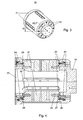
- Fig. 1 shows an inner cone 01, which is attached to a roller support arm 02 of a not shown in this view reel changer.
- the inner cone 01 comprises a plurality of, in particular four, inner clamping jaws 03 distributed on its circumference, which are radially adjustable via a toggle mechanism 04.
- the toggle mechanism 04 operates in the manner by a control axis 06 is displaced in the axial direction.
- Adjusting elements 07 which are movably mounted on the adjusting axis 06, engage in bulges 08 of the inner clamping jaws 03 and stretch by sliding along the bulges 08 of the inner clamping jaws 03 like a screen, whereby the inner clamping jaws 03 are moved in the radial direction to the outside.
- clamping mechanism can also be embodied in other ways, for example by an axial movement of an actuating piston with conical piston sections, which interact with correspondingly shaped sections of the clamping jaws.
- a leaf spring package 05 is z. B. from at least one leaf spring 09 and an additional leaf spring ( Fig. 5 ).
- a centering cap 12 is provided, which facilitates threading of a material sleeve of a roll of material during Aufachsvorgang by their conical shape.
- An ejector 13, z. B. Auswerferility 13 with a detachable inner part 14 is provided on Rollentragarm 02 to realize an ejector for empty material sleeves, which will be explained later in more detail.
- Fig. 2 shows a spatial representation of the inner clamping jaw 03.
- the bulges 08 are already described radial adjustment of the inner clamping jaws 03 by means of the toggle mechanism 04.
- At the cone base body 11 facing end surfaces of the inner clamping jaw 03 each have a groove 16 is provided, in which the inner leaf springs 09 mounted in the State intervenes.
- the inner jaws 03 continue to have two holes 17, whose function will be discussed later.
- the holes 17 are preferably provided with an internal thread.
- Preferably axially extending webs 18 are provided on the radially outwardly directed surfaces of the inner clamping jaws 03, which are pressed during clamping of a material sleeve in the sleeve body to improve in this way the torque transmission.
- the leaf springs 09 and 24 are preferably always installed together as a "spring package” to achieve the provision of all jaws (inner and outer jaws).
- FIG. 3 an outer cone 19 of the clamping cone is shown in a spatial representation.
- the outer cone 19 are distributed on the circumference in openings, in particular in slots, z. B.
- four outer clamping jaws 21 stored.
- the outer clamping jaws 21 are arranged radially movable in the slots.
- Holes 22 are used to attach the outer cone 19 on the cone base body 11.
- the outer cone 19 is preferably formed sleeve-shaped or cup-shaped.
- Fig. 4 shows a longitudinal section of the Au .konus 19 along in Fig. 3 indicated section line III - III.
- the outer cone 19 has an inner cavity 23 which substantially corresponds to the size of the inner cone 01 when the inner clamping jaws 03 are retracted.
- the outer clamping jaws 21 are mounted with a radial freedom of movement in the outer cone 19. This storage is realized by dowel pins 26, which are firmly clamped on the one hand in the outer cone 19 and on the other hand engage in a lateral groove 27 of the outer clamping jaw 21. Furthermore, a lateral bore 28, immediately following the lateral groove 27, provided in the outer clamping jaw 21, in which the dowel pin 26 can be knocked from the outside, to allow disassembly of the outer clamping jaws 21, if necessary.
- the outer clamping jaws 21 are at their axial ends by at least one outer spring 24, for. B. an outer leaf spring 24, in particular outer leaf spring packets 25, which are arranged between outer cone 19 and outer clamping jaws 21, returned in the radial direction.
- the outer leaf springs 24 engage in a lateral notch 29, which is provided on the end faces of the outer clamping jaws 21.
- Fig. 5 is a leaf spring package 05, consisting of a leaf spring 09 and another leaf spring shown.
- the inner leaf spring 09 is preferably made of a spring steel strip and offers a high tensile strength. Due to their bias, the inner clamping jaws 03 are reset when relieved to an inner position.
- the inner leaf spring 09 is preferably made of a flat metal band, which is biased arcuately. It can also summarized several leaves (spring layers) with different lengths and biases to a leaf spring package which is held together by a common heart bolt and spring clips. By inserted plastic flakes or lubrication with grease, the friction is reduced when the ends of the layers move by length change during compression against each other.
- the Au dspannbacken 21 on the roller support arm 02 facing side on a chamfer 30.
- the centering cap 12 must be removed for this purpose.
- the in Fig. 1 shown intermediate ring 15 on the inner cone 01 also advantageously has grooves, not shown, in which the outer clamping jaws 21 slide on pushing the outer cone 19 along.
- Fig. 6 shows the outer clamping jaw 21 in a three-dimensional representation.
- the Au dspannbacke 21 preferably has two longitudinally extending webs 31, which press into the sleeve material during the clamping process.
- the lateral groove 27 and the lateral bore 28 can be seen, in which the clamping pin 26 engages in the mounted state.
- a two-sided lateral notch 29 can be seen, in which engages the outer leaf spring packets 25 in the mounted state.
- the chamfer 30 at the front of the outer clamping jaw 21 is indicated by the dashed lines.
- Radially extending continuous fastening bores 32 serve for fastening the outer clamping jaws 21 to the inner clamping jaws 03 in the assembled state of the outer cone 19 on the inner cone 01.
- Fig. 5 shows an outer leaf spring 24 of the leaf spring package 25 in a three-dimensional view. This is like the inner leaf spring 09 preferably made of spring leaf steel.
- the inner leaf spring assembly 05 and the outer leaf spring package 25 each have the provision for resetting the inner clamping jaws 03 and the Outer clamping jaws 21 required bias on.
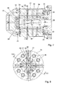
- Fig. 7 the clamping cone for the inclusion of material rolls of the second type (6 inches) is shown.
- the outer cone 19 is pushed onto the inner cone 01.
- the position of the outer cone 19 above the inner cone 01 is fixed via preferably two arranged in the cone body 11 keyways 33.
- the feather keys 33 are arranged on the front side of the outer cone 19 on the roller support arm 02 facing side. At the same time, the feather keys 33 contribute to the transmission of torque in the operating state of the roll changer.
- the outer cone 19 has on its side facing the Rollentragarm 02 side of the shape of the key 33 corresponding recess or groove.
- the inner clamping jaws 03 are connected to the outer clamping jaws 21 by screws 34 and are now reset simultaneously by the inner leaf springs 09 and the outer leaf springs 24.
- the radial adjusting mechanism takes place as already in Fig. 1 described by the adjusting axis 06 is displaced in the axial direction, wherein the toggle mechanism 04 actuates the adjusting elements 07.
- the radial displacement of the inner clamping jaws 03 thus causes a similar radial displacement of the outer clamping jaws 21st
- Fig. 8 shows the clamping cone according to Fig. 7 in a cross-sectional view along the section line VII - VII in Fig. 7 ,
- the outer clamping jaws 21 are in the deferred state of the outer cone 19 on the inner clamping jaws 03 in an afflicted with sufficient clearance surface guide, which is a joint operation by the toggle mechanism 04 and a common provision on the inner leaf springs 09 and the outer leaf springs 24th allowed.
- Der Outer cone 19 is in the embodiment shown about eight screws 36, preferably Allen screws, which extend through the outer cone 19 in the axial direction, attached to the cone body 11.
- An inner diameter d23 of the cavity 23 of the outer cone 19 is unchangeable.
- An outer diameter D11 of the cone base body is in the technical sense (in the tolerances) equal to the inner diameter d23 of the outer cone.
- the outer cone 19 is preferably immovably fixed to the cone body 11.
- a centering cap 38 is attached to the free end of the outer cone 19.
- the centering cap 38 also serves as an additional safeguard for the screws 36.
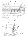
- a second inner part 39 is to be mounted in the ejector 13 prior to assembly of the outer cone 19, which functionally replaces the first inner part 14, which is needed to realize the Auswerferfunktion with exclusively used inner cone 01.
- Fig. 10 in which the roll support arm 02 of the roll changer is shown with the clamping cone, the function of the sleeve ejector can be explained.
- the outer cone 19 mounted on the inner cone 01, the clamping cone so set up for receiving a 6-inch sleeve.
- the tube ejector is designed as a stationary construction, ie it contains no rotating parts.
- the tube ejector includes a ring piston 41, shown schematically, which is pneumatically operated.
- the ejector 13 is with Push rods 42 connected, which rest loosely on the annular piston 41.
- the annular piston 41 presses on the push rods 42 and moves the ejector 13 in the direction of the free end of the clamping cone, whereby an empty winding tube from the clamping cone (here outer cone 19) is stripped off.
- a return of the ejector 13 is preferably carried out by tension springs, not shown, which retract the push rods 42 back to their original position, while the pressure side of the annular piston 41 is vented.
- limit switches in the vicinity of the ejector 13, by which a query of the position of the ejector 13 is realized.
- the centering cap 12 is removed from the inner cone 01 and the first inner part 14 of the ejector 13 dismantled.
- the second inner part 39 is now to be mounted.
- the outer cone 19 can be postponed.
- the position of the outer cone 19 is fixed by the feather keys 33, which engage in two grooves of the outer cone 19.
- the outer cone 19 is now screwed by eight screws 36 on the cone body 11.
- the centering cap 38 is then set up and tightened. By the screws 34, the outer clamping jaws 21 are attached to the inner clamping jaws 03.
- the assembled or disassembled position of the outer cone 19 can be queried. It is therefore always possible to determine at the operator station whether the roll changer is equipped for a 3-inch or 6-inch sleeve.
- the inner clamping jaws 03 are a first type of roller arranged with first sleeve inner diameter (eg 3 inches) supporting.
- first sleeve inner diameter eg 3 inches
- no outer cone 19 is arranged on the inner cone 01.
- the outer jaws are arranged to carry a second type of reel having a second inner diameter (eg, 6 inches) different from the first inner diameter of the sleeve.
Landscapes
- Unwinding Webs (AREA)
- Replacement Of Web Rolls (AREA)
- Rolls And Other Rotary Bodies (AREA)
- Winding Of Webs (AREA)
Claims (24)
- Changeur de rouleaux avec un cône de serrage pour le support d'un tube avec un rouleau de matériau enroulé, dans lequel :- un cône intérieur (01) est disposé avec un corps de base de cone (11) et une pluralité de mâchoires de serrage intérieures (03), réparties sur la périphérie du cône intérieur (01), fixé sur un bras support de rouleau (02) du changeur de rouleaux,- un cône extérieur (19) est disposé avec une pluralité de mâchoires de serrage extérieures (21), réparties sur sa périphérie, et un espace creux (23), s'étendant axialement à l'intérieur,- les mâchoires de serrage extérieures (21) étant disposées dans des ouvertures du cône extérieur (19),- le cône intérieur (01) étant disposé dans l'espace creux (23) du cône extérieur (19),- les mâchoires de serrage extérieures (23) étant réglables radialement.
- Changeur de rouleaux selon la revendication 1, caractérisé en ce que les ouvertures sont des fentes.
- Changeur de rouleaux selon la revendication 3, caractérisé en ce que les mâchoires de serrage extérieures (21) sont disposées de manière déplaçable radialement dans les fentes.
- Changeur de rouleaux selon la revendication 1, caractérisé en ce que le cône extérieur (19) est conformé en tube ou en pot.
- Changeur de rouleaux selon la revendication 1, caractérisé en ce qu'un diamètre intérieur (d23) de l'espace creux (23) du cône extérieur (19) n'est pas modifiable.
- Changeur de rouleaux selon la revendication 1, caractérisé en ce qu'un diamètre intérieur (d23) de l'espace creux (23) du cône extérieur (19) est égal à un diamètre extérieur (D11) de corps de base de cône (11).
- Changeur de rouleaux selon la revendication 1, caractérisé en ce que le cône extérieur (19) est fixé de manière indéplaçable sur le corps de base de cône (11).
- Changeur de rouleaux selon la revendication 1, caractérisé en ce que, à l'aide de moyens de réglage (06, 07), les mâchoires de serrage intérieures (03) sont déplaçables radialement vers l'extérieur et, lorsque le cône extérieur (19) est enfilé, les mâchoires de serrage extérieures (21) sont déplaçables radialement vers l'extérieur par l'intermédiaire des mâchoires de serrage intérieures (03) accouplées.
- Changeur de rouleaux selon la revendication 1, caractérisé en ce que les mâchoires de serrage intérieures (03) sont réglables radialement et sont fixées en un état rétracté et en un état déployé.
- Changeur de rouleaux selon la revendication 1, caractérisé en ce que les mâchoires de serrage intérieures (03) sont déplaçables radialement vers l'extérieur dans l'état déployé, par l'intermédiaire d'un système à levier à genouillère (04).
- Changeur de rouleaux selon la revendication 1, caractérisé en ce que les mâchoires de serrage intérieures (03) sont rétractables à l'état rétracté chacune au moyen d'au moins un ressort intérieur (09), disposé entre la mâchoire de serrage intérieure (03) et le corps de base de cône (11), par l'intermédiaire de la force élastique.
- Changeur de rouleaux selon la revendication 1, caractérisé en ce que des faces frontales des mâchoires de serrage extérieures (21) présentent en direction axiale un entaillage (29) latéral, dans lequel le au moins un ressort extérieur (24), disposé dans le cône extérieur (19), s'engage.
- Changeur de rouleaux selon la revendication 11 ou 12, caractérisé en ce que le ressort intérieur (09) et/ou le ressort extérieur (24) est/sont réalisé(s) sous forme de ressort à lame (09 ; 24).
- Changeur de rouleaux selon la revendication 13, caractérisé en ce que le ressort à lame intérieur (09) est disposé dans un paquet de ressorts à lame intérieur (05) et/ou le ressort à lame extérieur (24) est disposé dans est disposé dans un paquet de ressorts à lame (25).
- Changeur de bouleaux selon la revendication 1 ou 12, caractérisé en ce que les mâchoires de serrage extérieures (21) présentent une rainure latérale (27), dans laquelle s'engage une tige de serrage (26) disposée dans le cône extérieur (19).
- Changeur de rouleaux selon l'une des revendications 1 à 15, caractérisé en ce que, lorsque le cône extérieur (19) est à l'état monté, les mâchoires de serrage extérieures (21) sont disposées sur les mâchoires de serrage intérieures (03) du cône intérieur (01).
- Changeur de rouleaux selon la revendication 16, caractérisé en ce que chacune des mâchoires de serrage extérieures (21) est susceptible d'être vissée, ou reliée d'une autre manière, à la mâchoire de serrage intérieure (03) se trouvant chaque fois au-dessous.
- Changeur de rouleaux selon l'une des revendications 1 à 17, caractérisé en ce que les mâchoires de serrage extérieures (21) présentent, sur une face tournée vers l'extrémité libre du cône de serrage et l'espace creux (23), un chanfreinage (30).
- Changeur de rouleaux selon l'une des revendications 1 à 18, caractérisé en ce que des clavettes d'ajustage (33), servant à la fixation en position du cône extérieur (19), sont disposées entre le corps de base de cône (11) et le cône extérieur (19).
- Changeur de rouleaux selon l'une des revendications 1 à 19, caractérisé en ce que le cône de serrage comprend en outre un initiateur, identifiant le cône extérieur (19) monté et envoyant une information d'état à un pupitre de service.
- Changeur de rouleaux selon l'une des revendications 1 à 20, caractérisé en ce que le cône de serrage comprend en outre un éjecteur (13), adapté a cône intérieur ou extérieur (03 ; 19) chaque fois utilisé au moyen d'une parie intérieure (14 ; 3) interchangeable, un tube résiduel étant retiré du cône de serrage par un déplacement axial de l'éjecteur (13).
- Changeur de rouleaux selon la revendication 18, caractérisé en ce que l'actionnement de l'éjecteur (13) s'effectue en direction axiale, au moyen d'un piston annulaire (42) actionné pneumatiquement, disposé dans le bras support de rouleau (02).
- Changeur de rouleaux selon la revendication 22, caractérisé en ce que des initiateurs sont disposés, détectant par palpage les positions finales de l'éjecteur (13).
- Changeur de rouleaux selon la revendication 22, caractérisé en ce que l'éjecteur (13) est réalisé sous forme de disque éjecteur (13).
Applications Claiming Priority (1)
| Application Number | Priority Date | Filing Date | Title |
|---|---|---|---|
| DE102007024768A DE102007024768B4 (de) | 2007-05-26 | 2007-05-26 | Spannkonus zur Aufnahme unterschiedlicher Typen von Materialrollen in einem Rollenwechsler |
Publications (3)
| Publication Number | Publication Date |
|---|---|
| EP1997757A2 EP1997757A2 (fr) | 2008-12-03 |
| EP1997757A3 EP1997757A3 (fr) | 2009-04-08 |
| EP1997757B1 true EP1997757B1 (fr) | 2011-03-30 |
Family
ID=39712288
Family Applications (1)
| Application Number | Title | Priority Date | Filing Date |
|---|---|---|---|
| EP08151344A Active EP1997757B1 (fr) | 2007-05-26 | 2008-02-13 | Changeur de rouleaux avec un cône de serrage pour le support d'un tube avec un rouleau de matériau enroulé |
Country Status (3)
| Country | Link |
|---|---|
| EP (1) | EP1997757B1 (fr) |
| AT (1) | ATE503713T1 (fr) |
| DE (2) | DE102007024768B4 (fr) |
Cited By (1)
| Publication number | Priority date | Publication date | Assignee | Title |
|---|---|---|---|---|
| IT202200000188A1 (it) * | 2022-01-10 | 2023-07-10 | M E C Mech Engineering Consulting Srl | Adattatore di diametro per un dispositivo di blocco di anime per alberi di bobinatrici |
Families Citing this family (5)
| Publication number | Priority date | Publication date | Assignee | Title |
|---|---|---|---|---|
| DE102010002524B4 (de) | 2010-03-03 | 2013-07-18 | Koenig & Bauer Aktiengesellschaft | Vorrichtung zur Aufnahme zumindest einer Materialrolle |
| DE102011017508B4 (de) | 2011-04-26 | 2013-12-24 | Koenig & Bauer Aktiengesellschaft | Spanndorn einer Rollenabspulvorrichtung |
| CN108217340B (zh) * | 2017-12-29 | 2019-05-21 | 杭州大华工控技术有限公司 | 分切机气胀式收卷夹头 |
| CN112058945B (zh) * | 2020-08-18 | 2022-09-20 | 湖南科美达重工有限公司 | 一种棱锥套式卷取机卷筒 |
| DE202023104200U1 (de) | 2023-07-26 | 2023-08-21 | Manroland Goss Web Systems Gmbh | Spannadapter für Substratrollen |
Family Cites Families (12)
| Publication number | Priority date | Publication date | Assignee | Title |
|---|---|---|---|---|
| FR768300A (fr) * | 1933-04-24 | 1934-08-03 | Mandrin extensible pour travaux d'enroulement ou autres | |
| GB683550A (en) * | 1949-04-05 | 1952-12-03 | Edward Arno Crosby | Improvements relating to devices for winding paper or other flexible sheet material on tubular cores or unwinding it therefrom |
| US2904279A (en) | 1957-02-06 | 1959-09-15 | Lynn H Ewing | Expanding chuck |
| US3610643A (en) * | 1969-07-03 | 1971-10-05 | Great Northern Paper Co | Chuck adapter |
| DE3439628C2 (de) * | 1984-10-30 | 1995-12-07 | Schloemann Siemag Ag | Haspel mit aufsteckbarer Hülse |
| US4651643A (en) * | 1985-02-14 | 1987-03-24 | Sidney Katz | Adaptors for use with printing cylinder mandrels |
| JPH0213413Y2 (fr) * | 1985-09-02 | 1990-04-13 | ||
| JPH10211519A (ja) | 1997-01-27 | 1998-08-11 | Sumitomo Metal Ind Ltd | リール装置 |
| US6491252B2 (en) * | 2000-04-07 | 2002-12-10 | Sankyo Seiki Mfg, Co., Ltd. | Winding core holding mechanism, roll medium holding device having the same, and winding device using said mechanism and device |
| DE10056274B4 (de) | 2000-09-25 | 2004-10-14 | Koenig & Bauer Ag | Spanndorn |
| JP3928705B2 (ja) | 2002-03-20 | 2007-06-13 | セイコーエプソン株式会社 | ロール状記録媒体の保持手段及び記録装置 |
| JP2007090707A (ja) | 2005-09-29 | 2007-04-12 | Seiko I Infotech Inc | ロール体保持装置および記録装置とロール体保持方法。 |
-
2007
- 2007-05-26 DE DE102007024768A patent/DE102007024768B4/de not_active Expired - Fee Related
-
2008
- 2008-02-13 DE DE502008002993T patent/DE502008002993D1/de active Active
- 2008-02-13 EP EP08151344A patent/EP1997757B1/fr active Active
- 2008-02-13 AT AT08151344T patent/ATE503713T1/de active
Cited By (2)
| Publication number | Priority date | Publication date | Assignee | Title |
|---|---|---|---|---|
| IT202200000188A1 (it) * | 2022-01-10 | 2023-07-10 | M E C Mech Engineering Consulting Srl | Adattatore di diametro per un dispositivo di blocco di anime per alberi di bobinatrici |
| EP4209441A1 (fr) * | 2022-01-10 | 2023-07-12 | M.E.C. Mechanical Engineering Consulting Srl | Adaptateur de diametre pour dispositif de blocage de noyaux de bobinage d'arbres de machines |
Also Published As
| Publication number | Publication date |
|---|---|
| DE502008002993D1 (de) | 2011-05-12 |
| DE102007024768A1 (de) | 2008-12-04 |
| EP1997757A3 (fr) | 2009-04-08 |
| ATE503713T1 (de) | 2011-04-15 |
| EP1997757A2 (fr) | 2008-12-03 |
| DE102007024768B4 (de) | 2011-04-07 |
Similar Documents
| Publication | Publication Date | Title |
|---|---|---|
| DE2552607C2 (de) | Handwerkzeug zum Aufweiten von Rohrleitungsenden | |
| EP1997757B1 (fr) | Changeur de rouleaux avec un cône de serrage pour le support d'un tube avec un rouleau de matériau enroulé | |
| EP1719725B1 (fr) | Tête de serrage pour une refendeuse-bobineuse | |
| EP1104347B1 (fr) | Dispositif de retenue pour manchons d'impression flexographique | |
| DE2719853C3 (de) | Spulenhalter | |
| DE19538262A1 (de) | Spulenhalter für eine oder mehrere, hintereinander angeordnete Spulen | |
| EP1320429B1 (fr) | Procede et dispositif pour former un rebord ou un bord a l'extremite d'un tube en tole | |
| EP3283243B1 (fr) | Dispositif à cylindres annulaires comportant des paliers à roulement axialement fixes | |
| DE2344230C2 (de) | Vorrichtung zum Aufspannen von Wickelhülsen | |
| DE102005056649B3 (de) | Vorrichtung zum Halten von wenigstens zwei Walzen einer Walzmaschine und Walzmaschine | |
| DE102008000065B4 (de) | Spannkonus zur Aufnahme einer auf eine Wickelhülse aufgewickelten Materialrolle | |
| DE3045537A1 (de) | Vorrichtung zum verbinden des spannbackentraegers eines werkstueck-spannfutters mit einem spannzylinder | |
| EP0613410B1 (fr) | Instrument pour la realisation de profils interieurs sans enlevement de copeaux | |
| DE2354742A1 (de) | Werkzeugmaschine mit einer fuehrung fuer werkstoffstangen | |
| DE4308738A1 (de) | Spann- und Löseeinrichtung für Schaftwerkzeuge | |
| DE19649324C2 (de) | Umfangsveränderbarer Rotationskörper | |
| DE3150319C2 (fr) | ||
| DE1499775A1 (de) | Doppelnabe fuer Spulen | |
| EP0286010B1 (fr) | Anneau de centrage des barres de matière première pour tours | |
| DE3147863A1 (de) | Verfahren und vorrichtung zum befestigen eines radier-gummis an einem bleistift | |
| DE3235318A1 (de) | Spanneinrichtung zum innenspannen von rohrkoepern | |
| EP0680799B1 (fr) | Dispositif de fixation et serrage, notamment pour dispositifs de mesure et réglage | |
| EP1555072B1 (fr) | Tête de roulage des filets axial | |
| DE202016102778U1 (de) | Klapplager | |
| DE4138126A1 (de) | Werkzeug zur spanlosen herstellung von aussen- oder innenkonturen an werkstuecken |
Legal Events
| Date | Code | Title | Description |
|---|---|---|---|
| PUAI | Public reference made under article 153(3) epc to a published international application that has entered the european phase |
Free format text: ORIGINAL CODE: 0009012 |
|
| AK | Designated contracting states |
Kind code of ref document: A2 Designated state(s): AT BE BG CH CY CZ DE DK EE ES FI FR GB GR HR HU IE IS IT LI LT LU LV MC MT NL NO PL PT RO SE SI SK TR |
|
| AX | Request for extension of the european patent |
Extension state: AL BA MK RS |
|
| PUAL | Search report despatched |
Free format text: ORIGINAL CODE: 0009013 |
|
| AK | Designated contracting states |
Kind code of ref document: A3 Designated state(s): AT BE BG CH CY CZ DE DK EE ES FI FR GB GR HR HU IE IS IT LI LT LU LV MC MT NL NO PL PT RO SE SI SK TR |
|
| AX | Request for extension of the european patent |
Extension state: AL BA MK RS |
|
| 17P | Request for examination filed |
Effective date: 20090313 |
|
| AKX | Designation fees paid |
Designated state(s): AT BE BG CH CY CZ DE DK EE ES FI FR GB GR HR HU IE IS IT LI LT LU LV MC MT NL NO PL PT RO SE SI SK TR |
|
| 17Q | First examination report despatched |
Effective date: 20100112 |
|
| RTI1 | Title (correction) |
Free format text: ROLL CHANGER WITH A CLAMPING CONE FOR SUPPORTING A CORE WITH A COILED ROLL OF MATERIAL |
|
| GRAP | Despatch of communication of intention to grant a patent |
Free format text: ORIGINAL CODE: EPIDOSNIGR1 |
|
| GRAS | Grant fee paid |
Free format text: ORIGINAL CODE: EPIDOSNIGR3 |
|
| GRAA | (expected) grant |
Free format text: ORIGINAL CODE: 0009210 |
|
| AK | Designated contracting states |
Kind code of ref document: B1 Designated state(s): AT BE BG CH CY CZ DE DK EE ES FI FR GB GR HR HU IE IS IT LI LT LU LV MC MT NL NO PL PT RO SE SI SK TR |
|
| REG | Reference to a national code |
Ref country code: GB Ref legal event code: FG4D Free format text: NOT ENGLISH |
|
| REG | Reference to a national code |
Ref country code: CH Ref legal event code: EP |
|
| REG | Reference to a national code |
Ref country code: IE Ref legal event code: FG4D |
|
| REF | Corresponds to: |
Ref document number: 502008002993 Country of ref document: DE Date of ref document: 20110512 Kind code of ref document: P |
|
| REG | Reference to a national code |
Ref country code: DE Ref legal event code: R096 Ref document number: 502008002993 Country of ref document: DE Effective date: 20110512 |
|
| REG | Reference to a national code |
Ref country code: NL Ref legal event code: VDEP Effective date: 20110330 |
|
| PG25 | Lapsed in a contracting state [announced via postgrant information from national office to epo] |
Ref country code: HR Free format text: LAPSE BECAUSE OF FAILURE TO SUBMIT A TRANSLATION OF THE DESCRIPTION OR TO PAY THE FEE WITHIN THE PRESCRIBED TIME-LIMIT Effective date: 20110330 Ref country code: LV Free format text: LAPSE BECAUSE OF FAILURE TO SUBMIT A TRANSLATION OF THE DESCRIPTION OR TO PAY THE FEE WITHIN THE PRESCRIBED TIME-LIMIT Effective date: 20110330 Ref country code: SE Free format text: LAPSE BECAUSE OF FAILURE TO SUBMIT A TRANSLATION OF THE DESCRIPTION OR TO PAY THE FEE WITHIN THE PRESCRIBED TIME-LIMIT Effective date: 20110330 Ref country code: LT Free format text: LAPSE BECAUSE OF FAILURE TO SUBMIT A TRANSLATION OF THE DESCRIPTION OR TO PAY THE FEE WITHIN THE PRESCRIBED TIME-LIMIT Effective date: 20110330 Ref country code: GR Free format text: LAPSE BECAUSE OF FAILURE TO SUBMIT A TRANSLATION OF THE DESCRIPTION OR TO PAY THE FEE WITHIN THE PRESCRIBED TIME-LIMIT Effective date: 20110701 |
|
| LTIE | Lt: invalidation of european patent or patent extension |
Effective date: 20110330 |
|
| PG25 | Lapsed in a contracting state [announced via postgrant information from national office to epo] |
Ref country code: FI Free format text: LAPSE BECAUSE OF FAILURE TO SUBMIT A TRANSLATION OF THE DESCRIPTION OR TO PAY THE FEE WITHIN THE PRESCRIBED TIME-LIMIT Effective date: 20110330 Ref country code: SI Free format text: LAPSE BECAUSE OF FAILURE TO SUBMIT A TRANSLATION OF THE DESCRIPTION OR TO PAY THE FEE WITHIN THE PRESCRIBED TIME-LIMIT Effective date: 20110330 Ref country code: NO Free format text: LAPSE BECAUSE OF FAILURE TO SUBMIT A TRANSLATION OF THE DESCRIPTION OR TO PAY THE FEE WITHIN THE PRESCRIBED TIME-LIMIT Effective date: 20110630 Ref country code: CY Free format text: LAPSE BECAUSE OF FAILURE TO SUBMIT A TRANSLATION OF THE DESCRIPTION OR TO PAY THE FEE WITHIN THE PRESCRIBED TIME-LIMIT Effective date: 20110330 |
|
| REG | Reference to a national code |
Ref country code: IE Ref legal event code: FD4D |
|
| PG25 | Lapsed in a contracting state [announced via postgrant information from national office to epo] |
Ref country code: EE Free format text: LAPSE BECAUSE OF FAILURE TO SUBMIT A TRANSLATION OF THE DESCRIPTION OR TO PAY THE FEE WITHIN THE PRESCRIBED TIME-LIMIT Effective date: 20110330 Ref country code: PT Free format text: LAPSE BECAUSE OF FAILURE TO SUBMIT A TRANSLATION OF THE DESCRIPTION OR TO PAY THE FEE WITHIN THE PRESCRIBED TIME-LIMIT Effective date: 20110801 |
|
| PG25 | Lapsed in a contracting state [announced via postgrant information from national office to epo] |
Ref country code: IS Free format text: LAPSE BECAUSE OF FAILURE TO SUBMIT A TRANSLATION OF THE DESCRIPTION OR TO PAY THE FEE WITHIN THE PRESCRIBED TIME-LIMIT Effective date: 20110730 Ref country code: RO Free format text: LAPSE BECAUSE OF FAILURE TO SUBMIT A TRANSLATION OF THE DESCRIPTION OR TO PAY THE FEE WITHIN THE PRESCRIBED TIME-LIMIT Effective date: 20110330 Ref country code: CZ Free format text: LAPSE BECAUSE OF FAILURE TO SUBMIT A TRANSLATION OF THE DESCRIPTION OR TO PAY THE FEE WITHIN THE PRESCRIBED TIME-LIMIT Effective date: 20110330 Ref country code: SK Free format text: LAPSE BECAUSE OF FAILURE TO SUBMIT A TRANSLATION OF THE DESCRIPTION OR TO PAY THE FEE WITHIN THE PRESCRIBED TIME-LIMIT Effective date: 20110330 Ref country code: ES Free format text: LAPSE BECAUSE OF FAILURE TO SUBMIT A TRANSLATION OF THE DESCRIPTION OR TO PAY THE FEE WITHIN THE PRESCRIBED TIME-LIMIT Effective date: 20110711 |
|
| PG25 | Lapsed in a contracting state [announced via postgrant information from national office to epo] |
Ref country code: NL Free format text: LAPSE BECAUSE OF FAILURE TO SUBMIT A TRANSLATION OF THE DESCRIPTION OR TO PAY THE FEE WITHIN THE PRESCRIBED TIME-LIMIT Effective date: 20110330 |
|
| PG25 | Lapsed in a contracting state [announced via postgrant information from national office to epo] |
Ref country code: IE Free format text: LAPSE BECAUSE OF FAILURE TO SUBMIT A TRANSLATION OF THE DESCRIPTION OR TO PAY THE FEE WITHIN THE PRESCRIBED TIME-LIMIT Effective date: 20110330 |
|
| PLBE | No opposition filed within time limit |
Free format text: ORIGINAL CODE: 0009261 |
|
| STAA | Information on the status of an ep patent application or granted ep patent |
Free format text: STATUS: NO OPPOSITION FILED WITHIN TIME LIMIT |
|
| PG25 | Lapsed in a contracting state [announced via postgrant information from national office to epo] |
Ref country code: PL Free format text: LAPSE BECAUSE OF FAILURE TO SUBMIT A TRANSLATION OF THE DESCRIPTION OR TO PAY THE FEE WITHIN THE PRESCRIBED TIME-LIMIT Effective date: 20110330 Ref country code: DK Free format text: LAPSE BECAUSE OF FAILURE TO SUBMIT A TRANSLATION OF THE DESCRIPTION OR TO PAY THE FEE WITHIN THE PRESCRIBED TIME-LIMIT Effective date: 20110330 |
|
| 26N | No opposition filed |
Effective date: 20120102 |
|
| REG | Reference to a national code |
Ref country code: DE Ref legal event code: R097 Ref document number: 502008002993 Country of ref document: DE Effective date: 20120102 |
|
| PGFP | Annual fee paid to national office [announced via postgrant information from national office to epo] |
Ref country code: CH Payment date: 20120227 Year of fee payment: 5 |
|
| PGFP | Annual fee paid to national office [announced via postgrant information from national office to epo] |
Ref country code: IT Payment date: 20120222 Year of fee payment: 5 |
|
| BERE | Be: lapsed |
Owner name: KOENIG & BAUER A.G. Effective date: 20120228 |
|
| PG25 | Lapsed in a contracting state [announced via postgrant information from national office to epo] |
Ref country code: MC Free format text: LAPSE BECAUSE OF NON-PAYMENT OF DUE FEES Effective date: 20120229 |
|
| PG25 | Lapsed in a contracting state [announced via postgrant information from national office to epo] |
Ref country code: BE Free format text: LAPSE BECAUSE OF NON-PAYMENT OF DUE FEES Effective date: 20120228 |
|
| PG25 | Lapsed in a contracting state [announced via postgrant information from national office to epo] |
Ref country code: BG Free format text: LAPSE BECAUSE OF FAILURE TO SUBMIT A TRANSLATION OF THE DESCRIPTION OR TO PAY THE FEE WITHIN THE PRESCRIBED TIME-LIMIT Effective date: 20110630 |
|
| PG25 | Lapsed in a contracting state [announced via postgrant information from national office to epo] |
Ref country code: MT Free format text: LAPSE BECAUSE OF FAILURE TO SUBMIT A TRANSLATION OF THE DESCRIPTION OR TO PAY THE FEE WITHIN THE PRESCRIBED TIME-LIMIT Effective date: 20110330 |
|
| REG | Reference to a national code |
Ref country code: CH Ref legal event code: PL |
|
| PG25 | Lapsed in a contracting state [announced via postgrant information from national office to epo] |
Ref country code: LI Free format text: LAPSE BECAUSE OF NON-PAYMENT OF DUE FEES Effective date: 20130228 Ref country code: CH Free format text: LAPSE BECAUSE OF NON-PAYMENT OF DUE FEES Effective date: 20130228 |
|
| PG25 | Lapsed in a contracting state [announced via postgrant information from national office to epo] |
Ref country code: IT Free format text: LAPSE BECAUSE OF NON-PAYMENT OF DUE FEES Effective date: 20130213 |
|
| REG | Reference to a national code |
Ref country code: AT Ref legal event code: MM01 Ref document number: 503713 Country of ref document: AT Kind code of ref document: T Effective date: 20130213 |
|
| PG25 | Lapsed in a contracting state [announced via postgrant information from national office to epo] |
Ref country code: TR Free format text: LAPSE BECAUSE OF FAILURE TO SUBMIT A TRANSLATION OF THE DESCRIPTION OR TO PAY THE FEE WITHIN THE PRESCRIBED TIME-LIMIT Effective date: 20110330 |
|
| PG25 | Lapsed in a contracting state [announced via postgrant information from national office to epo] |
Ref country code: AT Free format text: LAPSE BECAUSE OF NON-PAYMENT OF DUE FEES Effective date: 20130213 Ref country code: LU Free format text: LAPSE BECAUSE OF NON-PAYMENT OF DUE FEES Effective date: 20120213 |
|
| PG25 | Lapsed in a contracting state [announced via postgrant information from national office to epo] |
Ref country code: HU Free format text: LAPSE BECAUSE OF FAILURE TO SUBMIT A TRANSLATION OF THE DESCRIPTION OR TO PAY THE FEE WITHIN THE PRESCRIBED TIME-LIMIT Effective date: 20080213 |
|
| REG | Reference to a national code |
Ref country code: FR Ref legal event code: PLFP Year of fee payment: 8 |
|
| PGFP | Annual fee paid to national office [announced via postgrant information from national office to epo] |
Ref country code: FR Payment date: 20150223 Year of fee payment: 8 Ref country code: GB Payment date: 20150220 Year of fee payment: 8 |
|
| REG | Reference to a national code |
Ref country code: DE Ref legal event code: R081 Ref document number: 502008002993 Country of ref document: DE Owner name: KOENIG & BAUER AG, DE Free format text: FORMER OWNER: KOENIG & BAUER AKTIENGESELLSCHAFT, 97080 WUERZBURG, DE |
|
| GBPC | Gb: european patent ceased through non-payment of renewal fee |
Effective date: 20160213 |
|
| REG | Reference to a national code |
Ref country code: FR Ref legal event code: ST Effective date: 20161028 |
|
| PG25 | Lapsed in a contracting state [announced via postgrant information from national office to epo] |
Ref country code: GB Free format text: LAPSE BECAUSE OF NON-PAYMENT OF DUE FEES Effective date: 20160213 Ref country code: FR Free format text: LAPSE BECAUSE OF NON-PAYMENT OF DUE FEES Effective date: 20160229 |
|
| PGFP | Annual fee paid to national office [announced via postgrant information from national office to epo] |
Ref country code: DE Payment date: 20240301 Year of fee payment: 17 |