EP1996847B1 - Druckbehälterventil, insbesondere druckluftflaschenventil für ein druckluftatemgerät - Google Patents
Druckbehälterventil, insbesondere druckluftflaschenventil für ein druckluftatemgerät Download PDFInfo
- Publication number
- EP1996847B1 EP1996847B1 EP07722054A EP07722054A EP1996847B1 EP 1996847 B1 EP1996847 B1 EP 1996847B1 EP 07722054 A EP07722054 A EP 07722054A EP 07722054 A EP07722054 A EP 07722054A EP 1996847 B1 EP1996847 B1 EP 1996847B1
- Authority
- EP
- European Patent Office
- Prior art keywords
- valve
- discharge
- pressurized container
- supply
- opening
- Prior art date
- Legal status (The legal status is an assumption and is not a legal conclusion. Google has not performed a legal analysis and makes no representation as to the accuracy of the status listed.)
- Not-in-force
Links
Images
Classifications
-
- F—MECHANICAL ENGINEERING; LIGHTING; HEATING; WEAPONS; BLASTING
- F16—ENGINEERING ELEMENTS AND UNITS; GENERAL MEASURES FOR PRODUCING AND MAINTAINING EFFECTIVE FUNCTIONING OF MACHINES OR INSTALLATIONS; THERMAL INSULATION IN GENERAL
- F16K—VALVES; TAPS; COCKS; ACTUATING-FLOATS; DEVICES FOR VENTING OR AERATING
- F16K11/00—Multiple-way valves, e.g. mixing valves; Pipe fittings incorporating such valves
- F16K11/02—Multiple-way valves, e.g. mixing valves; Pipe fittings incorporating such valves with all movable sealing faces moving as one unit
- F16K11/06—Multiple-way valves, e.g. mixing valves; Pipe fittings incorporating such valves with all movable sealing faces moving as one unit comprising only sliding valves, i.e. sliding closure elements
- F16K11/072—Multiple-way valves, e.g. mixing valves; Pipe fittings incorporating such valves with all movable sealing faces moving as one unit comprising only sliding valves, i.e. sliding closure elements with pivoted closure members
- F16K11/074—Multiple-way valves, e.g. mixing valves; Pipe fittings incorporating such valves with all movable sealing faces moving as one unit comprising only sliding valves, i.e. sliding closure elements with pivoted closure members with flat sealing faces
-
- F—MECHANICAL ENGINEERING; LIGHTING; HEATING; WEAPONS; BLASTING
- F17—STORING OR DISTRIBUTING GASES OR LIQUIDS
- F17C—VESSELS FOR CONTAINING OR STORING COMPRESSED, LIQUEFIED OR SOLIDIFIED GASES; FIXED-CAPACITY GAS-HOLDERS; FILLING VESSELS WITH, OR DISCHARGING FROM VESSELS, COMPRESSED, LIQUEFIED, OR SOLIDIFIED GASES
- F17C13/00—Details of vessels or of the filling or discharging of vessels
- F17C13/04—Arrangement or mounting of valves
-
- G—PHYSICS
- G05—CONTROLLING; REGULATING
- G05D—SYSTEMS FOR CONTROLLING OR REGULATING NON-ELECTRIC VARIABLES
- G05D16/00—Control of fluid pressure
- G05D16/04—Control of fluid pressure without auxiliary power
- G05D16/10—Control of fluid pressure without auxiliary power the sensing element being a piston or plunger
- G05D16/101—Control of fluid pressure without auxiliary power the sensing element being a piston or plunger the controller being arranged as a multiple-way valve
-
- G—PHYSICS
- G05—CONTROLLING; REGULATING
- G05D—SYSTEMS FOR CONTROLLING OR REGULATING NON-ELECTRIC VARIABLES
- G05D16/00—Control of fluid pressure
- G05D16/04—Control of fluid pressure without auxiliary power
- G05D16/10—Control of fluid pressure without auxiliary power the sensing element being a piston or plunger
- G05D16/107—Control of fluid pressure without auxiliary power the sensing element being a piston or plunger with a spring-loaded piston in combination with a spring-loaded slideable obturator that move together over range of motion during normal operation
-
- F—MECHANICAL ENGINEERING; LIGHTING; HEATING; WEAPONS; BLASTING
- F17—STORING OR DISTRIBUTING GASES OR LIQUIDS
- F17C—VESSELS FOR CONTAINING OR STORING COMPRESSED, LIQUEFIED OR SOLIDIFIED GASES; FIXED-CAPACITY GAS-HOLDERS; FILLING VESSELS WITH, OR DISCHARGING FROM VESSELS, COMPRESSED, LIQUEFIED, OR SOLIDIFIED GASES
- F17C2205/00—Vessel construction, in particular mounting arrangements, attachments or identifications means
- F17C2205/03—Fluid connections, filters, valves, closure means or other attachments
- F17C2205/0302—Fittings, valves, filters, or components in connection with the gas storage device
- F17C2205/0323—Valves
-
- F—MECHANICAL ENGINEERING; LIGHTING; HEATING; WEAPONS; BLASTING
- F17—STORING OR DISTRIBUTING GASES OR LIQUIDS
- F17C—VESSELS FOR CONTAINING OR STORING COMPRESSED, LIQUEFIED OR SOLIDIFIED GASES; FIXED-CAPACITY GAS-HOLDERS; FILLING VESSELS WITH, OR DISCHARGING FROM VESSELS, COMPRESSED, LIQUEFIED, OR SOLIDIFIED GASES
- F17C2205/00—Vessel construction, in particular mounting arrangements, attachments or identifications means
- F17C2205/03—Fluid connections, filters, valves, closure means or other attachments
- F17C2205/0302—Fittings, valves, filters, or components in connection with the gas storage device
- F17C2205/0382—Constructional details of valves, regulators
-
- F—MECHANICAL ENGINEERING; LIGHTING; HEATING; WEAPONS; BLASTING
- F17—STORING OR DISTRIBUTING GASES OR LIQUIDS
- F17C—VESSELS FOR CONTAINING OR STORING COMPRESSED, LIQUEFIED OR SOLIDIFIED GASES; FIXED-CAPACITY GAS-HOLDERS; FILLING VESSELS WITH, OR DISCHARGING FROM VESSELS, COMPRESSED, LIQUEFIED, OR SOLIDIFIED GASES
- F17C2221/00—Handled fluid, in particular type of fluid
- F17C2221/03—Mixtures
- F17C2221/031—Air
-
- F—MECHANICAL ENGINEERING; LIGHTING; HEATING; WEAPONS; BLASTING
- F17—STORING OR DISTRIBUTING GASES OR LIQUIDS
- F17C—VESSELS FOR CONTAINING OR STORING COMPRESSED, LIQUEFIED OR SOLIDIFIED GASES; FIXED-CAPACITY GAS-HOLDERS; FILLING VESSELS WITH, OR DISCHARGING FROM VESSELS, COMPRESSED, LIQUEFIED, OR SOLIDIFIED GASES
- F17C2270/00—Applications
- F17C2270/07—Applications for household use
- F17C2270/079—Respiration devices for rescuing
Definitions
- the invention relates to a pressure vessel valve, in particular compressed air cylinder valve with integrated pressure reducer for a Druck Kunststoffatemêt, in particular a self-rescuer having a supply nozzle and a removal housing with a closable via a shut-off supply and removal channels.
- the breathing air required by a user is stored under high pressure to provide the user with a reduced, respirable pressure cylinder valve with integrated pressure reducer connected to the compressed air cylinder as needed.
- Valve fittings for pressure vessels are well known in the art.
- this describes DE 199 17 431 C2 a valve fitting connected to a pressure vessel comprising a valve body having a reservoir neck and a bleed port interconnected by a media passage.
- the valve housing is associated with a shut-off valve, which is actuated via a handwheel. By turning the handwheel, a closure element with integrated seal insert can be displaced against a main valve seat or lifted off from it, in order to release or close the media channel between the container nozzle and the extraction nozzle.
- a connected to the media channel in front of the sampling nozzle pressure regulator is further integrated to reduce the pressure of the air supplied from the pressure vessel to the height required for the consumer.
- a filler neck connected to the media channel check valve to fill the pressure vessel, such as a compressed air cylinder, against the action of the check valve with compressed air can.
- valve fittings are disadvantageous in connection with compressed air cylinders for SCBA insofar as to open the shut-off valve at least two revolutions of the handwheel are necessary to ensure the required for the pressure-reduced breathing air supply of the user function of the cylinder valve or accidents due to a too small opening angle of the shut-off valve avoid.
- shut-off device does not close or close sufficiently tight; so that from stocked, filled compressed air cylinders constantly a, albeit small, amount of air can escape imperceptibly. In use, the bottle is then not or not completely filled, resulting in a risk to the user.
- leakage losses can be particularly problematic with so-called self-propelled air compressors with hood, which are used for escape and self-rescue from pollutant-containing areas and are often not used over a very long period of time. During this period, the compressed air stored in very small compressed air cylinders can gradually escape, so that the safety of persons to be rescued in an emergency is not guaranteed.
- the known cylinder valves of the above type can also due to the structural design of the shut-off valve and required for the filling Non-return valve can be made only with considerable cost.
- the invention has for its object to develop a pressure vessel valve with integrated pressure reducer and a shut-off device for a SCBA, which can be produced inexpensively, ensures easy, reliable handling and improved sealing effect.
- the basic idea of the invention consists in a transversely divided to the flow direction training of the pressure vessel valve with two in the dividing plane fed on each other, preferably ceramic valve discs on the respective part, namely a pressure vessel attached to the supply nozzle and connected thereto, about a rotation axis rotatable or in the transverse direction linearly displaceable removal housing attached.
- a supply port connected to the feed port and a discharge port connected to the removal port is formed.
- the air supply can be released at superimposed openings. Otherwise, the closed surface of the valve disc held on the take-off housing sealingly rests on the supply bore and the air supply is interrupted.
- the contiguous surfaces of the ceramic valve discs are so smooth and flat, the consequent adhesive forces, although the linear or rotational Move the valve discs against each other, but at the same time ensure a secure seal.
- the thus formed, in particular for compressed air cylinders of SCBA and preferably used in self-restraints pressure vessel valve can be opened with less than one revolution, so that a connected breathing apparatus is ready for use immediately.
- the obturator formed of ceramic valve discs ensures a tight closure of compressed air cylinders, so that the leakage losses are low and self-respiratory breathing apparatus are still operational even after a long period of non-use. Due to the small number of components, the valve can be manufactured at low cost. It is reliable, robust and easy to handle.
- a further feature of the invention may be provided in the second, attached to the removal housing valve plate from the removal opening in the circumferential direction spaced filling opening which is aligned with a filling duct connected to a filling channel in the removal housing.
- the two valve discs by an elastic member, such as a spring or a ring made of elastic material, clamped together.
- an elastic member such as a spring or a ring made of elastic material
- the cross-sectional shape of the openings in the ceramic valve discs is preferably formed so that the Compressed air only gradually flows when opening the valve, that is, the flow-through initial cross-section is initially low.
- the supply and / or the removal opening may have a drop-shaped or triangular cross-section.
- a stop element is provided on the rotatable removal housing, which cooperates with end stops formed on the supply nozzle for fixing the removal or filling position.
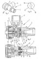
- the pressure vessel valve 1 comprises a for example to a compressed air cylinder (not shown) of a self-starter permanently connectable supply nozzle 2, a connected to the hood of the self-teaser removal housing 3 with a sampling nozzle 4 and connectable to a compressor filler 5 for filling the compressed air cylinder with compressed air.
- the supply nozzle 2 and the removal housing 3 are connected to the opposite end faces by means of a trained as a screw or pin, axially aligned fastener 6 rotatably connected to each other.
- a first valve disc 8 is held in a form-fitting manner in the circumferential direction.
- a feed opening 9 provided in the first valve disk 8 is in alignment with a feed channel 10 in the feed nozzle 2.
- a second valve disk 11 is fixed in a front-side recess of the take-off housing 3 and has a discharge opening 12 and a filling opening 13 spaced apart in the circumferential direction.
- the filling opening 13 is connected via a filling channel 14 with the screwed in the removal housing 3 filler 5.
- the two valve discs 8 and 11 are made of a ceramic material which is flat and smooth at the contact surfaces which are contiguous to one another over the entire area, so that the two valve discs 8 and 11 which can rotate relative to one another sealingly abut one another.
- the first (lower) valve disk 8 can be pressed under the action of a spring 21 against the upper valve disk 11.
- the sampling nozzle 4 is located in one firmly screwed onto the removal housing 3 lid 17th
- the integrated in the removal housing 3 pressure reducer is formed in a known manner and essentially comprises a standing under the action of a spring 18 and the pressure-reduced medium - the media supply from the pressure vessel before the air extraction from the pressure reducer for a short time interrupting - piston 19.
- a stop element 20 is mounted, which cooperates with the feed nozzle 2 formed stops (not shown). The stops fix the removal housing 3 and thus either the removal opening 12 or the filling opening 13 in a position aligned with the supply opening 9, while in the position between the two stops the supply opening 9 through the lying between the filling opening and the removal opening part of the second valve disc 11th is tightly closed.
- Fig. 2 is the pressure vessel valve 1 in the air supply to the user releasing position of the second valve disc 11 shown.
- valve The structural design of the valve is simple and the cost correspondingly low because there are only a few, directly in the valve housing integrated components, that is, the two valve discs for Absperrund filling 8 and 11, are required. The installation of a check valve in the filling line is unnecessary.
- the handling of the valve is very simple and safe. Already after a quarter turn of the removal housing a secure air supply to the user is guaranteed.
- the rotational movement of the removal housing 3 can also be made with the aid of the stop element.
- the stop member 20 may be connected to a string or the like to automatically release the air supply in conjunction with the handling of the self-rider. A slight opening of the shut-off valve during non-use and associated leaks, for example, by accidental impact with the valve body, are not possible because the air supply is released after a rotation of the sampling by about 90 °.
- the invention is not limited to the present embodiment.
- the two valve discs are not displaced relative to one another by a rotary movement but by another movement, for example a linear movement.
Landscapes
- Engineering & Computer Science (AREA)
- Physics & Mathematics (AREA)
- General Engineering & Computer Science (AREA)
- Fluid Mechanics (AREA)
- General Physics & Mathematics (AREA)
- Automation & Control Theory (AREA)
- Mechanical Engineering (AREA)
- Respiratory Apparatuses And Protective Means (AREA)
- Self-Closing Valves And Venting Or Aerating Valves (AREA)
- Valves And Accessory Devices For Braking Systems (AREA)
- Braking Systems And Boosters (AREA)
Description
- Die Erfindung betrifft ein Druckbehälterventil, insbesondere Druckluftflaschenventil mit integriertem Druckminderer für ein Druckluftatemgerät, insbesondere einen Selbstretter, das einen Zuführungsstutzen und ein Entnahmegehäuse mit über ein Absperrorgan verschließbaren Zuführungs- und Entnahmekanälen aufweist.
- In Druckluftflaschen für Atemgeräte wird die von einem Benutzer benötigte Atemluft unter hohem Druck gespeichert, um sie dem Benutzer bei Bedarf über ein mit der Druckluftflasche verbundenes Flaschenventil mit integriertem Druckminderer mit vermindertem, veratembarem Druck zur Verfügung zu stellen.
- Ventilarmaturen für Druckbehälter sind aus dem Stand der Technik hinreichend bekannt. Beispielsweise beschreibt die
DE 199 17 431 C2 eine an einen Druckbehälter angeschlossene Ventilarmatur, die ein Ventilgehäuse mit einem Behälterstutzen und einem Entnahmestutzen, die durch einen Medienkanal miteinander verbunden sind, umfasst. Dem Ventilgehäuse ist ein Absperrventil zugeordnet, das über ein Handrad betätigt wird. Durch Drehen des Handrades kann ein Verschlusselement mit eingegliederter Dichtungseinlage gegen einen Hauptventilsitz verlagert werden bzw. von diesem abgehoben werden, um den Medienkanal zwischen dem Behälterstutzen und dem Entnahmestutzen freizugeben oder zu verschließen. In das Ventilgehäuse ist weiterhin ein an den Medienkanal vor dem Entnahmestutzen angeschlossener Druckregler eingebunden, um den Druck der vom Druckbehälter zugeführten Luft auf die für den Verbraucher erforderliche Höhe zu reduzieren. Schließlich ist dem Ventilgehäuse ein Füllstutzen mit an den Medienkanal angeschlossenem Rückschlagventil zugeordnet, um den Druckbehälter, beispielsweise eine Druckluftflasche, entgegen der Wirkung des Rückschlagventils mit Druckluft befüllen zu können. - Derartige Ventilarmaturen sind in Verbindung mit Druckluftflaschen für Pressluftatmer insofern nachteilig, als zum Öffnen des Absperrventils mindestens zwei Umdrehungen des Handrades notwendig sind, um die für die druckgeminderte Atemluftversorgung des Benutzers erforderliche Funktion des Flaschenventils zu gewährleisten bzw. Unfälle aufgrund eines zu geringen Öffnungswinkels des Absperrventils zu vermeiden.
- Ein weiterer Nachteil der bekannten Flaschenventile besteht darin dass die Absperreinrichtung nicht ausreichend dicht schließt bzw. verschlossen ist; so dass aus bevorrateten, gefüllten Pressluftflaschen ständig eine, wenn auch geringe, Luftmenge unmerklich entweichen kann. Bei der Benutzung ist die Flasche dann nicht oder nicht vollständig gefüllt ist, woraus sich eine Gefährdung des Benutzers ergibt. Besonders problematisch können solche Leckageverluste bei sogenannten Druckluft-Selbstrettern mit Haube sein, die für die Flucht und Selbstrettung aus schadstoffhaltigen Bereichen eingesetzt werden und oft über einen sehr langen Zeitraum nicht genutzt werden. In diesem Zeitraum kann die in sehr kleinen Pressluftflaschen gespeicherte Druckluft allmählich entweichen, so dass die Sicherheit der in einem Notfall zu rettenden Personen nicht gewährleistet ist.
- Die bekannten Flaschenventile der oben genannten Art können zudem aufgrund der konstruktiven Ausbildung des Absperrventils und des für die Befüllung erforderlichen Rückschlagventils nur mit erheblichem Kostenaufwand gefertigt werden.
- Der Erfindung liegt die Aufgabe zugrunde, ein Druckbehälterventil mit integriertem Druckminderer und einer Absperrvorrichtung für ein Pressluftatemgerät zu entwickeln, das kostengünstig hergestellt werden kann, eine einfache, zuverlässige Handhabung sowie eine verbesserte Dichtwirkung gewährleistet.
- Erfindungsgemäß wird die Aufgabe mit einem gemäß den Merkmalen des Patentanspruchs 1 ausgebildeten Druckbehälterventil gelöst. Vorteilhafte Weiterbildungen und zweckmäßige Ausgestaltungen der Erfindung sind Gegenstand der Unteransprüche.
- Der Grundgedanke der Erfindung besteht in einer quer zur Durchströmungsrichtung geteilten Ausbildung des Druckbehälterventils mit zwei in der Teilungsebene satt aufeinander liegenden, vorzugsweise keramischen Ventilscheiben, die an dem jeweiligen Teil, nämlich einem am Druckbehälter befestigten Zuführungsstutzen und einem mit diesem verbundenen, um eine Drehachse verdrehbaren oder in Querrichtung linear verschiebbaren Entnahmegehäuse, befestigt sind. In den Ventilscheiben ist eine mit dem Zuführungsstutzen verbundene Zuführungsöffnung bzw. eine mit dem Entnahmegehäuse verbundene Entnahmeöffnung ausgebildet. Durch Verdrehen des beweglichen Entnahmegehäuses gegenüber dem feststehenden Zuführstutzen kann die Luftzufuhr bei übereinander liegenden Öffnungen freigegeben werden. Andernfalls liegt die geschlossene Fläche der am Entnahmegehäuse gehaltenen Ventilscheibe abdichtend auf der Zuführungsbohrung und die Luftzufuhr ist unterbrochen. Die aneinander liegenden Flächen der keramischen Ventilscheiben sind derart glatt und eben ausgebildet, das dadurch bedingte Adhäsionskräfte zwar das lineare oder rotatorische Verschieben der Ventilscheiben gegeneinander gestatten, aber gleichzeitig eine sichere Abdichtung gewährleisten.
- Das so ausgebildete, insbesondere für Druckluftflaschen von Pressluftatmern und vorzugsweise bei Selbstrettern verwendete Druckbehälterventil kann mit weniger als einer Umdrehung geöffnet werden, so dass ein angeschlossenes Atemgerät sofort einsatzbereit ist. Darüber hinaus gewährleist das aus keramischen Ventilscheiben gebildete Absperrorgan ein dichtes Verschließen von Druckluftflaschen, so dass die Leckageverluste gering sind und Selbstretter-Atemgeräte auch nach langer Zeit der Nichtbenutzung immer noch einsatzfähig sind. Aufgrund der geringen Zahl an Bauteilen kann das Ventil mit geringem Kostenaufwand hergestellt werden. Es ist funktionssicher, robust und einfach zu handhaben.
- Gemäß einem weiteren Merkmal der Erfindung kann in der zweiten, am Entnahmegehäuse angebrachten Ventilplatte eine von der Entnahmeöffnung in Umfangsrichtung im Abstand angeordnete Füllöffnung vorgesehen sein, die mit einem an einen Füllstutzen angeschlossenen Füllkanal im Entnahmegehäuse fluchtet. Indem die Füllöffnung durch Verdrehen des Entnahmegehäuses auf die Zuführungsöffnung in der ersten Ventilplatte ausgerichtet wird, kann der Druckbehälter neu befüllt werden. Das normalerweise notwendige Rückschlagventil ist nicht mehr erforderlich.
- In Ausgestaltung der Erfindung werden die beiden Ventilscheiben durch ein elastisches Bauteil, wie zum Beispiel eine Feder oder einen ring aus elastischem Material, aneinander verspannt.
- Die Querschnittsform der Öffnungen in den keramischen Ventilscheiben ist vorzugsweise so ausgebildet, dass die Druckluft beim Öffnen des Ventils erst allmählich abströmt, das heißt, der durchströmte Anfangsquerschnitt zunächst gering ist. Beispielsweise kann die Zuführungs- und/oder die Entnahmeöffnung einen tropfen- oder dreieckförmigen Querschnitt haben.
- In weiterer Ausgestaltung der Erfindung ist an dem drehbaren Entnahmegehäuse ein Anschlagelement vorgesehen, das mit am Zuführungsstutzen ausgebildeten Endanschlägen zur Fixierung der Entnahme- bzw. Füllposition zusammenwirkt.
- Ein Ausführungsbeispiel der Erfindung wird anhand der Zeichnung näher erläutert. Es zeigen:
- Fig. 1
- eine perspektivische Ansicht eines Druckluftflaschenventils mit angeschraubtem Füllstutzen;
- Fig. 2
- eine seitliche Schnittansicht des Druckluftflaschenventils nach
Fig. 1 in einer geöffneten, die Luftzufuhr zum Benutzer freigebenden Position; - Fig. 3
- eine Draufsicht der im drehbaren Gehäuseteil gehaltenen Ventilscheibe; und
- Fig. 4
- eine Schnittansicht des Druckluftflaschenventils ohne Füllstutzen.
- Wie
Fig. 1 zeigt, umfasst das Druckbehälterventil 1 einen beispielsweise an eine Druckluftflasche (nicht dargestellt) eines Selbstretters fest anschließbaren Zuführungsstutzen 2, ein mit der Haube des Selbstretters verbundenes Entnahmegehäuse 3 mit einem Entnahmestutzen 4 und einen an einen Kompressor anschließbaren Füllstutzen 5 zum Befüllen der Druckluftflasche mit Druckluft. Der Zuführungsstutzen 2 und das Entnahmegehäuse 3 sind an den gegenüberliegenden Stirnseiten mittels eines als Schraube oder Stift ausgebildeten, axial ausgerichteten Befestigungsmittels 6 zueinander drehbeweglich verbunden. In einer stirnseitigen Ausnehmung 7 des Zuführungsstutzens 2 ist eine erste Ventilscheibe 8 in Umfangsrichtung formschlüssig gehalten. Eine in der ersten Ventilscheibe 8 vorgesehene Zuführungsöffnung 9 fluchtet mit einem Zuführungskanal 10 im Zuführungsstutzen 2. In einer stirnseitigen Ausnehmung des Entnahmegehäuses 3 ist eine zweite Ventilscheibe 11 formschlüssig fixiert, die - in Umfangsrichtung voneinander beabstandet - eine Entnahmeöffnung 12 und eine Füllöffnung 13 aufweist. Die Füllöffnung 13 ist über einen Füllkanal 14 mit dem im Entnahmegehäuse 3 verschraubten Füllstutzen 5 verbunden. - Die beidene Ventilscheiben 8 und 11 bestehen aus einem keramischen Material, das an den vollflächig aneinander grenzenden Berührungsflächen eben und glatt ausgebildet ist, so dass die beiden gegeneinander verdrehbaren Ventilscheiben 8 und 11 abdichtend aneinander liegen. Zur Unterstützung der innigen Berührung der beiden Ventilscheiben 8 und 11 kann die erste (untere) Ventilscheibe 8 unter der Wirkung einer Feder 21 gegen die obere Ventilscheibe 11 gedrückt werden. Durch Verdrehen des Entnahmegehäuses 3 gegen den feststehenden Zuführungsstutzen 2 kann entweder die Entnahmeöffnung 12 - wie in
Fig. 2 dargestellt - oder die Füllöffnung 13 in eine mit der Zuführungsöffnung 9 und damit dem Zuführungskanal 10 übereinstimmende Position gebracht werden, so dass entweder von einem Kompressor erzeugte Luft in den Druckbehälter geleitet oder aus dem Druckbehälter entnommene Luft über in dem Entnahmegehäuse 3 sowie in einem in dieses integrierten Druckminderer ausgebildete Kanäle 15 und 16 in den Entnahmestutzen 4 und von dort zur Haube (zum Benutzer) gelangen kann. Der Entnahmestutzen 4 befindet sich in einem fest auf das Entnahmegehäuse 3 geschraubten Deckel 17. - Der in das Entnahmegehäuse 3 integrierte Druckminderer ist in bekannter Weise ausgebildet und umfasst im Wesentlichen einen unter der Wirkung einer Feder 18 und des druckreduzierten Mediums stehenden - die Medienzufuhr aus dem Druckbehälter vor der Luftentnahme aus dem Druckminderer kurzzeitig unterbrechenden - Kolben 19. An der Außenseite des Entnahmegehäuses 3 ist ein Anschlagelement 20 angebracht, das mit am Zuführungsstutzen 2 ausgebildeten Anschlägen (nicht dargestellt) zusammenwirkt. Die Anschläge fixieren das Entnahmegehäuse 3 und damit entweder die Entnahmeöffnung 12 oder die Füllöffnung 13 in einer mit der Zuführungsöffnung 9 fluchtendenden Position, während in der Position zwischen den beiden Anschlägen die Zuführungsöffnung 9 durch den zwischen der Füllöffnung und der Entnahmeöffnung liegenden Teil der zweiten Ventilscheibe 11 dicht verschlossen ist.
- In
Fig. 2 ist das Druckbehälterventil 1 in der die Luftzufuhr zum Benutzer freigebenden Position der zweiten Ventilscheibe 11 dargestellt. - Die Verwendung der beiden unter der Wirkung von Adhäsionskräften aneinander liegenden, aber gegeneinander verdrehbaren keramischen Ventilscheiben 8 und 11 gewährleistet ein sicheres Verschließen des Druckbehälters und eine deutliche Verringerung der Leckageverluste. Dadurch sind beispielsweise Selbstretter auch nach einem langen Zeitraum der Nichtbenutzung zuverlässig einsetzbar.
- Der konstruktive Aufbau des Ventils ist einfach und der Kostenaufwand entsprechend gering, da für den Absperrund Füllvorgang nur wenige, unmittelbar in das Ventilgehäuse integrierte Bauteile, das heißt, die beiden Ventilscheiben 8 und 11, erforderlich sind. Der Einbau eines Rückschlagventils in die Füllleitung erübrigt sich.
- Auch die Handhabung des Ventils ist denkbar einfach und sicher. Bereits nach einer Vierteldrehung des Entnahmegehäuses ist eine sichere Luftzufuhr zum Benutzer gewährleistet. Die Drehbewegung des Entnahmegehäuses 3 kann auch mit Hilfe des Anschlagelements vorgenommen werden. Bei der Verwendung des Ventils in Verbindung mit einem Selbstretter kann das Anschlagelement 20 mit einer Schnur oder dgl. verbunden werden, um in Verbindung mit der Handhabung des Selbstretters die Luftzufuhr automatisch freizugeben. Ein geringfügiges Öffnen des Absperrventils während der Nichtbenutzung und damit verbundene Leckagen, beispielsweise durch versehentliches Anstoßen an den Ventilkörper, sind nicht möglich, da die Luftzufuhr erst nach einer Drehung des Entnahmegehäuses um etwa 90° freigegeben wird.
- Die Erfindung ist nicht auf das vorliegende Ausführungsbeispiel beschränkt. Beispielsweise ist es bei einer konstruktiv anderen Verbindung der beiden separaten Ventilteile denkbar, dass die beiden Ventilscheiben nicht durch eine Drehbewegung, sondern durch eine andere Bewegung, z.B. eine Linearbewegung, gegeneinander verschoben werden.
-
- 1
- Druckbehälterventil
- 2
- Zuführungsstutzen
- 3
- Entnahmegehäuse
- 4
- Entnahmestutzen
- 5
- Füllstutzen
- 6
- Befestigungsmittel v. 2, 3
- 7
- Ausnehmung v. 2
- 8
- Erste Ventilscheibe
- 9
- Zuführungsöffnung
- 10
- Zuführungskanal
- 11
- Zweite Ventilscheibe
- 12
- Entnahmeöffnung v. 11
- 13
- Füllöffnung v. 11
- 14
- Füllkanal
- 15
- Kanäle in 3
- 16
- Kanäle in 19
- 17
- Deckel
- 18
- Feder
- 19
- Kolben
- 20
- Anschlagelement
- 21
- Feder
Claims (10)
- Druckbehälterventil, insbesondere Druckluftflaschenventil mit integriertem Druckminderer für ein Druckluftatemgerät, insbesondere einen Selbstretter, das einen Zuführungsstutzen (2) und ein Entnahmegehäuse (3) mit durch ein Absperrorgan (8, 11) verschließbaren Zuführungs- und Entnahmekanälen (10, 15) aufweist, dadurch gekennzeichnet, dass der Zuführungsstutzen (2) und das Entnahmegehäuse (3) separate, miteinander verspannte und durch eine Drehbewegung um eine Drehachse (6) oder eine Linearbewegung zueinander verschiebbare Ventilteile sind, wobei an dem jeweiligen Ventilteil - miteinander in unmittelbarer flächiger Berührung stehend - eine erste Ventilscheibe (8) mit einer an den Zuführungskanal (10) anschließenden Zuführungsöffnung (9) und eine zweite Ventilscheibe (11) mit einer an den Entnahmekanal (15, 16) anschließenden Entnahmeöffnung (12) befestigt ist.
- Druckbehälterventil nach Anspruch 1, dadurch gekennzeichnet, dass die zweite Ventilscheibe (11) eine in Umfangsrichtung von der Entnahmeöffnung (9) beabstandete Füllöffnung (13) aufweist, die über einen Füllkanal (14) mit einem am Entnahmegehäuse (3) lösbar befestigten Füllstutzen (5) zur Neubefüllung des Druckbehälters verbunden ist.
- Druckbehälterventil nach Anspruch 1 oder 2, dadurch gekennzeichnet, dass die beiden Ventilscheiben (8, 11) unter der Wirkung einer elastischen Bauteils aneinander pressbar sind.
- Druckbehälterventil nach Anspruch 3, dadurch gekennzeichnet, dass elastische Bauteil eine Schraubendruckfeder oder ein aus elastischem Material bestehender Ring ist.
- Druckbehälterventil nach Anspruch 1 oder 2, dadurch gekennzeichnet, dass an dem Entnahmegehäuse (3) ein Anschlagelement (20) angebracht ist, das mit am Zuführungsstutzen (2) ausgebildeten Endanschlägen zur Fixierung des Entnahmegehäuses (3) in der Entnahmeposition oder in der Füllposition zusammenwirkt.
- Druckbehälterventil nach Anspruch 5, dadurch gekennzeichnet, dass das Anschlagelement (20) mit einem flexiblen Betätigungsmittel zum automatischen Öffnen des Druckbehälterventils verbunden ist.
- Druckbehälterventil nach Anspruch 1, dadurch gekennzeichnet, dass das Entnahmegehäuse (3) über den Entnahmestutzen (4) mit einem Atemgerät in Verbindung steht und in das Entnahmegehäuse (3) ein Druckminderer (18, 19) zur Bereitstellung von veratembarer Luft integriert ist.
- Druckbehälterventil nach Anspruch 1, dadurch gekennzeichnet, dass die erste und zweite Ventilscheibe (8, 11) aus einem keramischen Material bestehen und deren einander berührende Flächen zur Ausbildung von Adhäsionskräften glatt und eben ausgebildet sind.
- Druckbehälterventil nach Anspruch 1, dadurch gekennzeichnet, dass die Querschnittsfläche der Zuführungs- und/oder der Entnahmeöffnungen (9, 12) so ausgebildet ist, dass das Abströmvolumen beim Öffnen des Ventils nur allmählich steigt.
- Druckbehälterventil nach Anspruch 9, dadurch gekennzeichnet, dass die Zuführungs- und/oder die Behälteröffnung (9, 12) eine tropfenförmige oder dreieckförmige Querschnittsfläche aufweist.
Applications Claiming Priority (2)
| Application Number | Priority Date | Filing Date | Title |
|---|---|---|---|
| DE102006012778A DE102006012778B3 (de) | 2006-03-17 | 2006-03-17 | Druckbehälterventil, insbesondere Druckluftflaschenventil für ein Druckluftatemgerät |
| PCT/DE2007/000491 WO2007110041A1 (de) | 2006-03-17 | 2007-03-15 | Druckbehälterventil, insbesondere druckluftflaschenventil für ein druckluftatemgerät |
Publications (2)
| Publication Number | Publication Date |
|---|---|
| EP1996847A1 EP1996847A1 (de) | 2008-12-03 |
| EP1996847B1 true EP1996847B1 (de) | 2009-09-16 |
Family
ID=38267652
Family Applications (1)
| Application Number | Title | Priority Date | Filing Date |
|---|---|---|---|
| EP07722054A Not-in-force EP1996847B1 (de) | 2006-03-17 | 2007-03-15 | Druckbehälterventil, insbesondere druckluftflaschenventil für ein druckluftatemgerät |
Country Status (5)
| Country | Link |
|---|---|
| US (1) | US8517020B2 (de) |
| EP (1) | EP1996847B1 (de) |
| AT (1) | ATE443224T1 (de) |
| DE (2) | DE102006012778B3 (de) |
| WO (1) | WO2007110041A1 (de) |
Families Citing this family (5)
| Publication number | Priority date | Publication date | Assignee | Title |
|---|---|---|---|---|
| DE102009052758B4 (de) * | 2009-11-12 | 2012-05-03 | Klaus Voll | Absperrventil |
| EP4186548A1 (de) | 2015-04-02 | 2023-05-31 | Hill-Rom Services PTE. LTD. | Maskenleckdetektion für eine atemvorrichtung |
| FR3051531B1 (fr) * | 2016-05-18 | 2019-08-16 | Yann RICORDEAU | Dispositif pour alimenter en air un utilisateur |
| AU2019321980A1 (en) * | 2018-08-14 | 2021-01-28 | CleanTech Swiss AG | Fitting for liquid gas bottles |
| CN110220005A (zh) * | 2019-05-31 | 2019-09-10 | 深圳市兰洋科技有限公司 | 智能阀 |
Family Cites Families (17)
| Publication number | Priority date | Publication date | Assignee | Title |
|---|---|---|---|---|
| US1364059A (en) * | 1917-01-09 | 1920-12-28 | Jones Owen Marshall | Valve |
| US1375205A (en) * | 1920-03-15 | 1921-04-19 | Budzinsky Tanas | Combination-faucet |
| US2906464A (en) * | 1956-11-15 | 1959-09-29 | Fay M Tomlinson | Hose nozzle |
| US3426797A (en) * | 1965-10-20 | 1969-02-11 | Willis Oil Tool Co | Multiple orifice valve |
| FR2030196A1 (de) | 1969-01-27 | 1970-10-30 | Ite Imperial Corp | |
| DE3539317A1 (de) * | 1985-11-06 | 1987-05-07 | Voss Armaturen | Schaltventil, insbesondere fuer pneumatische medien |
| US5088689A (en) * | 1988-10-31 | 1992-02-18 | Automatic Control Components, Inc. | Removable discharge sleeve in a disk valve |
| GB2233738A (en) | 1989-06-27 | 1991-01-16 | Intel Gasgards | Valve assemblies |
| DE4304621C2 (de) * | 1993-02-16 | 1995-05-04 | Bruehl Aluminiumtechnik | Ausgußverschluß |
| US5411059A (en) * | 1994-02-01 | 1995-05-02 | Essex Industries, Inc. | Multiple flow rate fluid control valve assembly |
| US5931181A (en) * | 1997-06-19 | 1999-08-03 | Emhart Inc. | Anti-scald faucet system |
| DE19917431C2 (de) | 1999-04-19 | 2001-04-12 | Vti Ventil Technik Gmbh | Ventilarmatur für einen Druckbehälter |
| US6601609B2 (en) * | 2001-06-01 | 2003-08-05 | Shane S. Taylor | Fluid flow control valve |
| FR2834771B1 (fr) | 2002-01-11 | 2004-02-13 | Gce Sas | Dispositif de robinet pour bouteille de gaz sous pression |
| DE10225003A1 (de) | 2002-06-06 | 2003-12-18 | Opel Adam Ag | Sicherheitsventil für Gasbehälter |
| EP1585003B1 (de) * | 2004-04-05 | 2008-01-30 | Flow Meter S.p.A. | Druckreduziervorrichtung für Gasflasche |
| US7748380B1 (en) * | 2004-04-06 | 2010-07-06 | Sti Licensing Corporation | Combined air-supplying/air-purifying system |
-
2006
- 2006-03-17 DE DE102006012778A patent/DE102006012778B3/de not_active Expired - Fee Related
-
2007
- 2007-03-15 AT AT07722054T patent/ATE443224T1/de active
- 2007-03-15 WO PCT/DE2007/000491 patent/WO2007110041A1/de not_active Ceased
- 2007-03-15 US US12/224,933 patent/US8517020B2/en not_active Expired - Fee Related
- 2007-03-15 EP EP07722054A patent/EP1996847B1/de not_active Not-in-force
- 2007-03-15 DE DE502007001547T patent/DE502007001547D1/de active Active
Also Published As
| Publication number | Publication date |
|---|---|
| EP1996847A1 (de) | 2008-12-03 |
| WO2007110041A1 (de) | 2007-10-04 |
| DE102006012778B3 (de) | 2007-10-31 |
| US20090301494A1 (en) | 2009-12-10 |
| US8517020B2 (en) | 2013-08-27 |
| ATE443224T1 (de) | 2009-10-15 |
| DE502007001547D1 (de) | 2009-10-29 |
Similar Documents
| Publication | Publication Date | Title |
|---|---|---|
| DE60018584T2 (de) | Einrichtung zur pumpverhütung | |
| DE69720093T2 (de) | Druckregler für die erste Stufe eines Atmungsgerätes und drehbares Durchlaufventil | |
| DE69304658T2 (de) | Das Nachfüllen verhinderndes Ventil für nicht nachfüllbare Behälter | |
| EP1996847B1 (de) | Druckbehälterventil, insbesondere druckluftflaschenventil für ein druckluftatemgerät | |
| DE818712C (de) | Kupplungs- und Selbstschlussventil | |
| DE2620170A1 (de) | Lungengesteuertes pressluftatemgeraet mit ueberdruck in der atemschutzmaske | |
| DE1124821B (de) | Lungengesteuertes Atemgaszufuehrungsventil fuer Atemschutzgeraete | |
| DE60127448T2 (de) | Servogesteuertes sicherheitsventil für behälter für toxische fluide | |
| DE2261762A1 (de) | Ventilsystem | |
| DE2206561A1 (de) | Ventil | |
| DE2343025A1 (de) | Abscherventil mit zerstoerbarem verbundstueck | |
| DE112015000242B4 (de) | Druckreduzier-Ventil für eine Löschanlage sowie Löschanlage mit einem derartigen Druckreduzier-Ventil | |
| DE2535600A1 (de) | Atemluftversorgungs-apparat mit einem oder mehreren fluktuations-ventilen, die auf einem perfektioniertem system ohne mechanische gelenkverbindungen beruhen | |
| DE7129218U (de) | Vakuum- vorrichtung | |
| WO2012065715A1 (de) | Vorrichtung zum ausbringen von reifendichtmittel aus einem behälter | |
| DE69015785T2 (de) | Neutralisierbares Reduzierventil. | |
| DE29604196U1 (de) | Absperrventil | |
| DE60121617T2 (de) | Ventile | |
| DE10005902B4 (de) | Füllanschluß | |
| DE7811860U1 (de) | Ansaugsteuervorrichtung fuer einen verdichter | |
| DE2926221A1 (de) | Kombinierter flaschenzapfverschluss | |
| DE1050201B (de) | ||
| EP3380780B1 (de) | Multifunktionsventil für einen gasbehälter | |
| DE7205258U (de) | Ventil | |
| DE1600937C3 (de) | Gasflaschenventil für aufsteckbare Membrandruckregler |
Legal Events
| Date | Code | Title | Description |
|---|---|---|---|
| PUAI | Public reference made under article 153(3) epc to a published international application that has entered the european phase |
Free format text: ORIGINAL CODE: 0009012 |
|
| 17P | Request for examination filed |
Effective date: 20080815 |
|
| AK | Designated contracting states |
Kind code of ref document: A1 Designated state(s): AT BE BG CH CY CZ DE DK EE ES FI FR GB GR HU IE IS IT LI LT LU LV MC MT NL PL PT RO SE SI SK TR |
|
| GRAP | Despatch of communication of intention to grant a patent |
Free format text: ORIGINAL CODE: EPIDOSNIGR1 |
|
| GRAS | Grant fee paid |
Free format text: ORIGINAL CODE: EPIDOSNIGR3 |
|
| GRAA | (expected) grant |
Free format text: ORIGINAL CODE: 0009210 |
|
| AK | Designated contracting states |
Kind code of ref document: B1 Designated state(s): AT BE BG CH CY CZ DE DK EE ES FI FR GB GR HU IE IS IT LI LT LU LV MC MT NL PL PT RO SE SI SK TR |
|
| REG | Reference to a national code |
Ref country code: GB Ref legal event code: FG4D Free format text: NOT ENGLISH |
|
| REG | Reference to a national code |
Ref country code: CH Ref legal event code: EP |
|
| REG | Reference to a national code |
Ref country code: IE Ref legal event code: FG4D |
|
| REF | Corresponds to: |
Ref document number: 502007001547 Country of ref document: DE Date of ref document: 20091029 Kind code of ref document: P |
|
| REG | Reference to a national code |
Ref country code: SE Ref legal event code: TRGR |
|
| PG25 | Lapsed in a contracting state [announced via postgrant information from national office to epo] |
Ref country code: FI Free format text: LAPSE BECAUSE OF FAILURE TO SUBMIT A TRANSLATION OF THE DESCRIPTION OR TO PAY THE FEE WITHIN THE PRESCRIBED TIME-LIMIT Effective date: 20090916 Ref country code: LT Free format text: LAPSE BECAUSE OF FAILURE TO SUBMIT A TRANSLATION OF THE DESCRIPTION OR TO PAY THE FEE WITHIN THE PRESCRIBED TIME-LIMIT Effective date: 20090916 |
|
| LTIE | Lt: invalidation of european patent or patent extension |
Effective date: 20090916 |
|
| PG25 | Lapsed in a contracting state [announced via postgrant information from national office to epo] |
Ref country code: LV Free format text: LAPSE BECAUSE OF FAILURE TO SUBMIT A TRANSLATION OF THE DESCRIPTION OR TO PAY THE FEE WITHIN THE PRESCRIBED TIME-LIMIT Effective date: 20090916 Ref country code: PL Free format text: LAPSE BECAUSE OF FAILURE TO SUBMIT A TRANSLATION OF THE DESCRIPTION OR TO PAY THE FEE WITHIN THE PRESCRIBED TIME-LIMIT Effective date: 20090916 Ref country code: NL Free format text: LAPSE BECAUSE OF FAILURE TO SUBMIT A TRANSLATION OF THE DESCRIPTION OR TO PAY THE FEE WITHIN THE PRESCRIBED TIME-LIMIT Effective date: 20090916 Ref country code: SI Free format text: LAPSE BECAUSE OF FAILURE TO SUBMIT A TRANSLATION OF THE DESCRIPTION OR TO PAY THE FEE WITHIN THE PRESCRIBED TIME-LIMIT Effective date: 20090916 |
|
| NLV1 | Nl: lapsed or annulled due to failure to fulfill the requirements of art. 29p and 29m of the patents act | ||
| PG25 | Lapsed in a contracting state [announced via postgrant information from national office to epo] |
Ref country code: CY Free format text: LAPSE BECAUSE OF FAILURE TO SUBMIT A TRANSLATION OF THE DESCRIPTION OR TO PAY THE FEE WITHIN THE PRESCRIBED TIME-LIMIT Effective date: 20090916 |
|
| REG | Reference to a national code |
Ref country code: IE Ref legal event code: FD4D |
|
| PG25 | Lapsed in a contracting state [announced via postgrant information from national office to epo] |
Ref country code: IE Free format text: LAPSE BECAUSE OF FAILURE TO SUBMIT A TRANSLATION OF THE DESCRIPTION OR TO PAY THE FEE WITHIN THE PRESCRIBED TIME-LIMIT Effective date: 20090916 Ref country code: ES Free format text: LAPSE BECAUSE OF FAILURE TO SUBMIT A TRANSLATION OF THE DESCRIPTION OR TO PAY THE FEE WITHIN THE PRESCRIBED TIME-LIMIT Effective date: 20091227 Ref country code: PT Free format text: LAPSE BECAUSE OF FAILURE TO SUBMIT A TRANSLATION OF THE DESCRIPTION OR TO PAY THE FEE WITHIN THE PRESCRIBED TIME-LIMIT Effective date: 20100118 Ref country code: EE Free format text: LAPSE BECAUSE OF FAILURE TO SUBMIT A TRANSLATION OF THE DESCRIPTION OR TO PAY THE FEE WITHIN THE PRESCRIBED TIME-LIMIT Effective date: 20090916 Ref country code: RO Free format text: LAPSE BECAUSE OF FAILURE TO SUBMIT A TRANSLATION OF THE DESCRIPTION OR TO PAY THE FEE WITHIN THE PRESCRIBED TIME-LIMIT Effective date: 20090916 Ref country code: CZ Free format text: LAPSE BECAUSE OF FAILURE TO SUBMIT A TRANSLATION OF THE DESCRIPTION OR TO PAY THE FEE WITHIN THE PRESCRIBED TIME-LIMIT Effective date: 20090916 Ref country code: IS Free format text: LAPSE BECAUSE OF FAILURE TO SUBMIT A TRANSLATION OF THE DESCRIPTION OR TO PAY THE FEE WITHIN THE PRESCRIBED TIME-LIMIT Effective date: 20100116 |
|
| PG25 | Lapsed in a contracting state [announced via postgrant information from national office to epo] |
Ref country code: SK Free format text: LAPSE BECAUSE OF FAILURE TO SUBMIT A TRANSLATION OF THE DESCRIPTION OR TO PAY THE FEE WITHIN THE PRESCRIBED TIME-LIMIT Effective date: 20090916 |
|
| PLBE | No opposition filed within time limit |
Free format text: ORIGINAL CODE: 0009261 |
|
| STAA | Information on the status of an ep patent application or granted ep patent |
Free format text: STATUS: NO OPPOSITION FILED WITHIN TIME LIMIT |
|
| PG25 | Lapsed in a contracting state [announced via postgrant information from national office to epo] |
Ref country code: DK Free format text: LAPSE BECAUSE OF FAILURE TO SUBMIT A TRANSLATION OF THE DESCRIPTION OR TO PAY THE FEE WITHIN THE PRESCRIBED TIME-LIMIT Effective date: 20090916 |
|
| 26N | No opposition filed |
Effective date: 20100617 |
|
| BERE | Be: lapsed |
Owner name: MSA AUER G.M.B.H. Effective date: 20100331 |
|
| PG25 | Lapsed in a contracting state [announced via postgrant information from national office to epo] |
Ref country code: GR Free format text: LAPSE BECAUSE OF FAILURE TO SUBMIT A TRANSLATION OF THE DESCRIPTION OR TO PAY THE FEE WITHIN THE PRESCRIBED TIME-LIMIT Effective date: 20091217 Ref country code: MC Free format text: LAPSE BECAUSE OF NON-PAYMENT OF DUE FEES Effective date: 20100331 |
|
| PG25 | Lapsed in a contracting state [announced via postgrant information from national office to epo] |
Ref country code: BE Free format text: LAPSE BECAUSE OF NON-PAYMENT OF DUE FEES Effective date: 20100331 |
|
| PG25 | Lapsed in a contracting state [announced via postgrant information from national office to epo] |
Ref country code: IT Free format text: LAPSE BECAUSE OF FAILURE TO SUBMIT A TRANSLATION OF THE DESCRIPTION OR TO PAY THE FEE WITHIN THE PRESCRIBED TIME-LIMIT Effective date: 20090916 |
|
| PG25 | Lapsed in a contracting state [announced via postgrant information from national office to epo] |
Ref country code: MT Free format text: LAPSE BECAUSE OF FAILURE TO SUBMIT A TRANSLATION OF THE DESCRIPTION OR TO PAY THE FEE WITHIN THE PRESCRIBED TIME-LIMIT Effective date: 20090916 |
|
| REG | Reference to a national code |
Ref country code: CH Ref legal event code: PL |
|
| PG25 | Lapsed in a contracting state [announced via postgrant information from national office to epo] |
Ref country code: CH Free format text: LAPSE BECAUSE OF NON-PAYMENT OF DUE FEES Effective date: 20110331 Ref country code: LI Free format text: LAPSE BECAUSE OF NON-PAYMENT OF DUE FEES Effective date: 20110331 |
|
| PG25 | Lapsed in a contracting state [announced via postgrant information from national office to epo] |
Ref country code: HU Free format text: LAPSE BECAUSE OF FAILURE TO SUBMIT A TRANSLATION OF THE DESCRIPTION OR TO PAY THE FEE WITHIN THE PRESCRIBED TIME-LIMIT Effective date: 20100317 Ref country code: BG Free format text: LAPSE BECAUSE OF FAILURE TO SUBMIT A TRANSLATION OF THE DESCRIPTION OR TO PAY THE FEE WITHIN THE PRESCRIBED TIME-LIMIT Effective date: 20090916 Ref country code: LU Free format text: LAPSE BECAUSE OF NON-PAYMENT OF DUE FEES Effective date: 20100315 |
|
| PG25 | Lapsed in a contracting state [announced via postgrant information from national office to epo] |
Ref country code: TR Free format text: LAPSE BECAUSE OF FAILURE TO SUBMIT A TRANSLATION OF THE DESCRIPTION OR TO PAY THE FEE WITHIN THE PRESCRIBED TIME-LIMIT Effective date: 20090916 |
|
| REG | Reference to a national code |
Ref country code: AT Ref legal event code: MM01 Ref document number: 443224 Country of ref document: AT Kind code of ref document: T Effective date: 20120315 |
|
| PG25 | Lapsed in a contracting state [announced via postgrant information from national office to epo] |
Ref country code: AT Free format text: LAPSE BECAUSE OF NON-PAYMENT OF DUE FEES Effective date: 20120315 |
|
| PGFP | Annual fee paid to national office [announced via postgrant information from national office to epo] |
Ref country code: SE Payment date: 20140311 Year of fee payment: 8 |
|
| PGFP | Annual fee paid to national office [announced via postgrant information from national office to epo] |
Ref country code: FR Payment date: 20140311 Year of fee payment: 8 |
|
| PGFP | Annual fee paid to national office [announced via postgrant information from national office to epo] |
Ref country code: GB Payment date: 20140312 Year of fee payment: 8 |
|
| PGFP | Annual fee paid to national office [announced via postgrant information from national office to epo] |
Ref country code: DE Payment date: 20140417 Year of fee payment: 8 |
|
| REG | Reference to a national code |
Ref country code: DE Ref legal event code: R082 Ref document number: 502007001547 Country of ref document: DE Representative=s name: MAIKOWSKI & NINNEMANN PATENTANWAELTE, DE |
|
| REG | Reference to a national code |
Ref country code: DE Ref legal event code: R081 Ref document number: 502007001547 Country of ref document: DE Owner name: MSA EUROPE GMBH, CH Free format text: FORMER OWNER: MSA AUER GMBH, 12059 BERLIN, DE Effective date: 20150303 Ref country code: DE Ref legal event code: R082 Ref document number: 502007001547 Country of ref document: DE Representative=s name: MAIKOWSKI & NINNEMANN PATENTANWAELTE, DE Effective date: 20150303 |
|
| REG | Reference to a national code |
Ref country code: DE Ref legal event code: R119 Ref document number: 502007001547 Country of ref document: DE |
|
| GBPC | Gb: european patent ceased through non-payment of renewal fee |
Effective date: 20150315 |
|
| PG25 | Lapsed in a contracting state [announced via postgrant information from national office to epo] |
Ref country code: SE Free format text: LAPSE BECAUSE OF NON-PAYMENT OF DUE FEES Effective date: 20150316 |
|
| REG | Reference to a national code |
Ref country code: SE Ref legal event code: EUG |
|
| REG | Reference to a national code |
Ref country code: FR Ref legal event code: ST Effective date: 20151130 |
|
| PG25 | Lapsed in a contracting state [announced via postgrant information from national office to epo] |
Ref country code: GB Free format text: LAPSE BECAUSE OF NON-PAYMENT OF DUE FEES Effective date: 20150315 Ref country code: DE Free format text: LAPSE BECAUSE OF NON-PAYMENT OF DUE FEES Effective date: 20151001 |
|
| PG25 | Lapsed in a contracting state [announced via postgrant information from national office to epo] |
Ref country code: FR Free format text: LAPSE BECAUSE OF NON-PAYMENT OF DUE FEES Effective date: 20150331 |
|
| P01 | Opt-out of the competence of the unified patent court (upc) registered |
Effective date: 20230626 |