EP1996376B1 - Robot programmable et interface utilisateur - Google Patents
Robot programmable et interface utilisateur Download PDFInfo
- Publication number
- EP1996376B1 EP1996376B1 EP07735028.8A EP07735028A EP1996376B1 EP 1996376 B1 EP1996376 B1 EP 1996376B1 EP 07735028 A EP07735028 A EP 07735028A EP 1996376 B1 EP1996376 B1 EP 1996376B1
- Authority
- EP
- European Patent Office
- Prior art keywords
- robot
- tool
- programming
- user interface
- touch screen
- Prior art date
- Legal status (The legal status is an assumption and is not a legal conclusion. Google has not performed a legal analysis and makes no representation as to the accuracy of the status listed.)
- Active
Links
- 230000033001 locomotion Effects 0.000 claims description 36
- 230000009471 action Effects 0.000 claims description 13
- 230000008859 change Effects 0.000 claims description 5
- 238000000034 method Methods 0.000 description 23
- 239000012636 effector Substances 0.000 description 15
- 230000005019 pattern of movement Effects 0.000 description 12
- 230000011218 segmentation Effects 0.000 description 7
- WDLTVNWWEZJMPF-UHFFFAOYSA-N 1,2,3,5-tetrachloro-4-(2,3-dichlorophenyl)benzene Chemical compound ClC1=CC=CC(C=2C(=C(Cl)C(Cl)=CC=2Cl)Cl)=C1Cl WDLTVNWWEZJMPF-UHFFFAOYSA-N 0.000 description 6
- 238000013519 translation Methods 0.000 description 6
- 230000004913 activation Effects 0.000 description 4
- 230000003287 optical effect Effects 0.000 description 4
- 238000012545 processing Methods 0.000 description 4
- 210000000707 wrist Anatomy 0.000 description 4
- 238000013459 approach Methods 0.000 description 3
- 230000006870 function Effects 0.000 description 3
- 239000003973 paint Substances 0.000 description 3
- 238000012360 testing method Methods 0.000 description 3
- 230000005540 biological transmission Effects 0.000 description 2
- 235000019219 chocolate Nutrition 0.000 description 2
- 238000010276 construction Methods 0.000 description 2
- 238000013461 design Methods 0.000 description 2
- 238000012986 modification Methods 0.000 description 2
- 230000004048 modification Effects 0.000 description 2
- 230000008569 process Effects 0.000 description 2
- 238000005507 spraying Methods 0.000 description 2
- 230000003213 activating effect Effects 0.000 description 1
- XAGFODPZIPBFFR-UHFFFAOYSA-N aluminium Chemical compound [Al] XAGFODPZIPBFFR-UHFFFAOYSA-N 0.000 description 1
- 229910052782 aluminium Inorganic materials 0.000 description 1
- 239000004411 aluminium Substances 0.000 description 1
- 230000008878 coupling Effects 0.000 description 1
- 238000010168 coupling process Methods 0.000 description 1
- 238000005859 coupling reaction Methods 0.000 description 1
- 230000001419 dependent effect Effects 0.000 description 1
- 238000001514 detection method Methods 0.000 description 1
- 230000001627 detrimental effect Effects 0.000 description 1
- 230000000694 effects Effects 0.000 description 1
- 239000000463 material Substances 0.000 description 1
- 230000008672 reprogramming Effects 0.000 description 1
- 230000000284 resting effect Effects 0.000 description 1
- 239000007921 spray Substances 0.000 description 1
Images


Classifications
-
- B—PERFORMING OPERATIONS; TRANSPORTING
- B25—HAND TOOLS; PORTABLE POWER-DRIVEN TOOLS; MANIPULATORS
- B25J—MANIPULATORS; CHAMBERS PROVIDED WITH MANIPULATION DEVICES
- B25J19/00—Accessories fitted to manipulators, e.g. for monitoring, for viewing; Safety devices combined with or specially adapted for use in connection with manipulators
- B25J19/0004—Braking devices
-
- B—PERFORMING OPERATIONS; TRANSPORTING
- B25—HAND TOOLS; PORTABLE POWER-DRIVEN TOOLS; MANIPULATORS
- B25J—MANIPULATORS; CHAMBERS PROVIDED WITH MANIPULATION DEVICES
- B25J18/00—Arms
-
- B—PERFORMING OPERATIONS; TRANSPORTING
- B25—HAND TOOLS; PORTABLE POWER-DRIVEN TOOLS; MANIPULATORS
- B25J—MANIPULATORS; CHAMBERS PROVIDED WITH MANIPULATION DEVICES
- B25J9/00—Programme-controlled manipulators
- B25J9/16—Programme controls
- B25J9/1656—Programme controls characterised by programming, planning systems for manipulators
- B25J9/1671—Programme controls characterised by programming, planning systems for manipulators characterised by simulation, either to verify existing program or to create and verify new program, CAD/CAM oriented, graphic oriented programming systems
-
- G—PHYSICS
- G05—CONTROLLING; REGULATING
- G05B—CONTROL OR REGULATING SYSTEMS IN GENERAL; FUNCTIONAL ELEMENTS OF SUCH SYSTEMS; MONITORING OR TESTING ARRANGEMENTS FOR SUCH SYSTEMS OR ELEMENTS
- G05B19/00—Programme-control systems
- G05B19/02—Programme-control systems electric
- G05B19/42—Recording and playback systems, i.e. in which the programme is recorded from a cycle of operations, e.g. the cycle of operations being manually controlled, after which this record is played back on the same machine
- G05B19/425—Teaching successive positions by numerical control, i.e. commands being entered to control the positioning servo of the tool head or end effector
-
- G—PHYSICS
- G05—CONTROLLING; REGULATING
- G05B—CONTROL OR REGULATING SYSTEMS IN GENERAL; FUNCTIONAL ELEMENTS OF SUCH SYSTEMS; MONITORING OR TESTING ARRANGEMENTS FOR SUCH SYSTEMS OR ELEMENTS
- G05B2219/00—Program-control systems
- G05B2219/30—Nc systems
- G05B2219/37—Measurements
- G05B2219/37138—Encoder and gear and absolute coder, give together absolute position of rotation
-
- G—PHYSICS
- G05—CONTROLLING; REGULATING
- G05B—CONTROL OR REGULATING SYSTEMS IN GENERAL; FUNCTIONAL ELEMENTS OF SUCH SYSTEMS; MONITORING OR TESTING ARRANGEMENTS FOR SUCH SYSTEMS OR ELEMENTS
- G05B2219/00—Program-control systems
- G05B2219/30—Nc systems
- G05B2219/39—Robotics, robotics to robotics hand
- G05B2219/39427—Panel on arm, hand of robot, controlled axis
-
- Y—GENERAL TAGGING OF NEW TECHNOLOGICAL DEVELOPMENTS; GENERAL TAGGING OF CROSS-SECTIONAL TECHNOLOGIES SPANNING OVER SEVERAL SECTIONS OF THE IPC; TECHNICAL SUBJECTS COVERED BY FORMER USPC CROSS-REFERENCE ART COLLECTIONS [XRACs] AND DIGESTS
- Y10—TECHNICAL SUBJECTS COVERED BY FORMER USPC
- Y10S—TECHNICAL SUBJECTS COVERED BY FORMER USPC CROSS-REFERENCE ART COLLECTIONS [XRACs] AND DIGESTS
- Y10S901/00—Robots
- Y10S901/19—Drive system for arm
- Y10S901/23—Electric motor
-
- Y—GENERAL TAGGING OF NEW TECHNOLOGICAL DEVELOPMENTS; GENERAL TAGGING OF CROSS-SECTIONAL TECHNOLOGIES SPANNING OVER SEVERAL SECTIONS OF THE IPC; TECHNICAL SUBJECTS COVERED BY FORMER USPC CROSS-REFERENCE ART COLLECTIONS [XRACs] AND DIGESTS
- Y10—TECHNICAL SUBJECTS COVERED BY FORMER USPC
- Y10T—TECHNICAL SUBJECTS COVERED BY FORMER US CLASSIFICATION
- Y10T74/00—Machine element or mechanism
- Y10T74/20—Control lever and linkage systems
- Y10T74/20207—Multiple controlling elements for single controlled element
- Y10T74/20305—Robotic arm
- Y10T74/20317—Robotic arm including electric motor
-
- Y—GENERAL TAGGING OF NEW TECHNOLOGICAL DEVELOPMENTS; GENERAL TAGGING OF CROSS-SECTIONAL TECHNOLOGIES SPANNING OVER SEVERAL SECTIONS OF THE IPC; TECHNICAL SUBJECTS COVERED BY FORMER USPC CROSS-REFERENCE ART COLLECTIONS [XRACs] AND DIGESTS
- Y10—TECHNICAL SUBJECTS COVERED BY FORMER USPC
- Y10T—TECHNICAL SUBJECTS COVERED BY FORMER US CLASSIFICATION
- Y10T74/00—Machine element or mechanism
- Y10T74/20—Control lever and linkage systems
- Y10T74/20207—Multiple controlling elements for single controlled element
- Y10T74/20305—Robotic arm
- Y10T74/20329—Joint between elements
Definitions
- the invention relates generally to programmable robot systems and robots and more specifically to user interface means for such robots, joints for such robots, methods for programming of such robots and databases for storing information relating to the programming and operations of the robot system.
- Programmable robots for use in industry are generally known.
- a traditional method of programming such robots consists of initially guiding the robot, for instance the tool or end effector on the robot arm from an initial point in space, for instance a pick-up location through a desired path in space leading to a final destination of the end effector, where an object initially picked up may be delivered.
- the robot or external control means are provided with storage means for storing information relating to the above movement from an initial to a final position. After this learning session the robot is able to repeat the procedure and carry out the task to be performed.
- Prior art programmable robot systems are disclosed in patent applications US 5 937 143 A , US 6 088 628 A , J P H 10 146782 A .
- a dedicated tracking device for tracking the desired path in space may also be employed, an example of such a system being for instance shown in US 5,495, 410 .
- the programming of robots used in industry requires specialised knowledge and can only be performed by persons skilled in the art, often referred to as system integrators.
- system integrators In connection with multi-purpose robots for use in industry or even at home, it would be advantageous to have access to a robot with user interface means facilitating quick and simple programming of the robot, including reprogramming from one task to another which can be performed by any person, not only a person with special skills within this art.
- a programmable robot provided with means for storing a number of working scenarios, i.e. information on the specific working procedures, initial and final positions of the end effector and trajectories in space of the end effector or other portions of the robot, characteristics of objects to be approached and handled by the robot and information on the surroundings limiting the allowable trajectories of portions of the robot, i.e. a description of the relevant characteristics, boundaries, objects, etc. in the surroundings.
- the above and other objects are according to the present invention attained by a programmable robot system, a control system for such a robot and user interface means for such a robot.
- the invention furthermore relates to a method for programming the robot using such interface means.
- the invention furthermore relates to a database for storing information relating to programming and operation of a robot and to a joint for use in a robot.
- the robot can be provided with sensor means for sensing the position of various portions (for instance the joints and/or the end effector) of the robot relative to the surroundings.
- said sensor means comprise one or more cameras, which can for instance be provided in the vicinity of the end effector and which can for instance be applied to identify and recognise objects to be handled by the robot or other relevant objects, boundaries etc. in the surroundings.
- the invention furthermore relates to a robot comprising:
- a very important aspect of the present invention relates to the user interface.
- the user interface does thus not primarily address the person skilled in the art of setting up and programming industrial robots but rather anybody employed in an industrial setting or even at home who quickly and yet reliably needs to apply a robot to a specific task or to change the application of a robot from one task to another
- the robot can be programmed and controlled from a standard personal computer running for instance a Windows program.
- An example of the programming of a robot according to the invention is given in the detailed description of the invention.
- Such programming and control may of course also be performed from a dedicated programming/control unit provided with a suitable man/machine interface comprising for instance a computer mouse and/or touch screen or other display screen and/or a keyboard.
- the PC or programming/control unit may also comprise the storage means described above.
- the user interface according to the invention may alternatively be distributed between an external user-accessible control means provided at appropriate portions of the robot, for instance on the various joints.
- the joints could be provided with control buttons for moving each individual joint during the initial programming session for instance in order to avoid collisions with objects or boundaries in the surroundings.
- Such local control members on the appropriate parts of the robot could if desired be supplemented with sensor means for sensing the proximity of for instance the joints or the end effector to objects or boundaries when the robot is actually working.
- the robot will at least to some extent be able to sense such changes and apply appropriate measures to counteract detrimental effects of such changes.
- the relevant objects and boundaries in the surroundings may be located using the robot itself, for instance by moving the end effector - or for that matter any other part of the robot - to a number of points characterising the object or boundaries sufficiently.
- a planar boundary may be defined my moving the end effector to at least three points on the boundary and via the interface means specifying the corresponding space coordinates, whereby a plane boundary will be specified.
- a curved boundary of course requires a larger number of Cartesian coordinates to be specified, but under certain circumstances (for instance spherical or cylindrical objects or boundaries) other co-ordinate systems my be applied for specifying their extension in space.
- the user interface means comprises a display screen on which a picture of the robot and optionally also relevant portions of the surroundings is shown at least during the programming session of the robot.
- the robot could optionally be remotely programmed in cases where access to the work area for some reason is undesired or even impossible, for instance by initially specifying the position of the relevant objects and boundaries of the work. Sequences showing the movement of the robot and the relevant portions of the surroundings corresponding to a number of work areas and operations of the robot may be stored in the storage means and retrieved when the robot changes from one application to another.
- a database comprising all relevant working scenarios of for instance an industrial plant may be gradually established, which greatly facilitates application of the robot for various purposes in an industrial setting or even at home.
- the present invention furthermore relates to a method for programming a robot according to the invention, a database for storing information relating to programming and operation of a robot and to a joint for use in a robot according to the invention. It is, however, understood that the method, database and joint according to the invention may also find application either together or separately in connection with other robots.
- the present invention relates to a programmable robot system, i.e. both to the robot itself, to the control system used for controlling the movements and functions of the robot including its end effector and storage means for storing pre-programmed movements and functions and relevant information about the objects to be handled by the robot and about the surrounding, in which the robot is working.
- the invention furthermore relates to a user interface used for communicating and controlling the robot at least during programming of the robot and furthermore for retrieving pre-programmed scenarios and patterns of movements etc. of the robot so that it can be used to perform different tasks for instance in an industrial setting without it being necessary to re-programme the robot for each new task.
- the robot is at least able to perform the following operations (functionalities): (a) a pick-and-place operation, (b) a filling operation, and (c) a palletising operation.
- operations or functionalities are implemented using a number of basic, primitive functionalities:
- a typical pick-and-place operation (a) Pattern of movement: Move to fixed initial position (b) Trigger: Light switch (c) Pattern of movement: Move to distance-controlled position (d) Action: Approach object (e) Action: Activate tool (f) Action: Move away from object (g) Pattern of movement: Through waypoints to fixed position (h) Action: De-activate tool (i) Pattern of movement: Through waypoints to fixed initial position A typical pattern of movement operation: (a) Pattern of movement: Move to fixed initial position (b) Trigger: Light switch (c) Pattern of movement: Move to distance-controlled position (d) Tracking: Distance-controlled tracking (e) Action: Activate tool (f) Trigger: Time (g) Action: De-activate tool (j) Pattern of movement: Through waypoints to fixed initial position A typical loading operation: (a) Pattern of movement: Move to fixed initial position (b) Trigger: Light switch (c) Pattern of movement: Position sequence with timing (d)
- the user interface comprises wizards, i.e. simple sequences of screen images or menus by means of which the user can specify the standard operations to be performed by the robot.
- a wizard for the pick-and-place operation will comprise a sequence of screen images corresponding to the sequence of functions of primitive functionalities described above. Exemplary embodiments of such wizards will be described in the following.
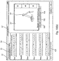
- FIG 1 there is shown a schematic perspective view of an embodiment of the robot according to the invention, set up to perform a simple pick-and-place operation, the view furthermore comprising definitions of Cartesian and spherical coordinates for characterising positions and orientations of various components of the robot. Definitions of coordinates in relation to the base and joints of the robot are given in figure 1(a) and definitions of the position and orientation of the tool are given in figure 1(b) .
- FIG 1(a) the shown embodiment of a robot according to the invention is generally designated by reference numeral 1 and consists of a base 2, 2' which can be attached to a surrounding structure, which is not shown.
- the robot according to this embodiment of the invention basically consists of two arm sections 4, 5 and 7, 8 connected to the base 2, 2' and the wrist section 9, 9', 10, 10', 11, 11' carrying a tool 12, respectively, which as an example may consist of a gripper 12 schematically shown in figures 1(a) and (b) .
- first interconnecting means comprising the sections 3 and 3'.
- the first interconnecting means are mounted for rotation about the longitudinal axis Z through the base 2, 2' as indicated by the angle ⁇ .
- the first arm section 4, 5 is mounted for rotation about the longitudinal axis 16 through the interconnecting means 3, 3' as indicated by the angle ⁇ .
- the first arm section 4, 5 is coupled to the second arm section 7, 8 via second interconnecting means or joints 6, 6', about the longitudinal axis 17 of which the second arm section 7, 8 is mounted for rotation (angle y).
- section 7, 8 is attached the wrist section 9, 9', 10, 10', 11, 11' carrying a tool 12.
- This section comprises three mutually perpendicular longitudinal axes 18, 19 and 20 through corresponding interconnecting means 9, 10 and 11.
- the orientation of each joint can be specified by the rotational angle about the corresponding axis of rotation, i.e. the angles ⁇ , ⁇ , ⁇ , ⁇ , ⁇ in the figure.
- the position for instance the X, Y, Z co-ordinates of the tool: (Xt, Yt, Zt)
- the orientation of the tool for instance defined by the co-ordinates: roll, pitch, yaw
- These co-ordinates are defined in figure 1(b) .
- the co-ordinate roll denotes a rotation around the longitudinal axis y' of the tool
- pitch denotes a rotation around the lateral axis x' through the tool
- yaw denotes a rotation around the vertical axis z' through the tool.
- the control system can determine the required set of angular orientations (rotational angles ⁇ , ⁇ , ⁇ , ⁇ , ⁇ ) of the joints from the position/orientation (X, Y, Z, roll, pitch, yaw) of the tool and vice versa.
- figure 1(a) shows schematically the robot set-up for use in a pick-and-place operation, where an object 14 (for instance a piece of chocolate) is placed on a conveyor 13 for pick up and placement in a box 15 placed adjacent the conveyor.
- the tool of the robot travels from an initial pick-up position or waypoint w1 through a number of chosen waypoints w2, w3 to its final placement destination w4.
- the number and position in space of these waypoints can be specified during the programming session of the robot as will be described in detail below
- FIG. 1 a specific embodiment of the robot according to the invention has been shown, but the robot according to the invention may be constructed in a number of different ways, for instance comprising different numbers of joints.
- FIG 2 shows a schematic perspective view of a second embodiment of the robot according to the invention comprising three joint
- figure 3 shows a schematic perspective view of a third embodiment of the robot according to the invention comprising four joints
- Figure 4 finally shows a schematic perspective view of a fourth embodiment of a robot according to the invention (a so-called "Scara-robot").
- the embodiment shown in figure 1 makes it in principle possible for the tool to attain any position and orientation in space, but in cases where more restricted movements of the robot and more restricted positions and orientations of the tool are required, less complicated embodiments as for instance shown in figures 2 , 3 and 4 may be applied.
- FIG 5 there is shown a schematic cross sectional side view of an interconnecting means or joint according to an embodiment of the invention comprising the main components: a transmission 22, a motor 23 and encoding and controlling means 24.
- the latter comprises an encoder for registering the rotational angle ⁇ , ⁇ , ⁇ , ⁇ , ⁇ , ⁇ of the particular joint.
- the encoder could consist of an optical encoder (relative/incremental or absolute) for instance comprising a disc 26 mounted for rotation with the motor 23 and provided with a pattern of through openings through which a light beam from a light source placed in a housing 27 may penetrate. Encoders of this kind are known for a variety of purposes.
- the motor drive axle 25 running longitudinally in the interconnecting means is hollow in order to allow for the passage of electrical leads, not shown, between the various portions of the robot.
- FIG 6 there is shown a schematic cross sectional side view of two adjacent interconnecting means (joints) for instance in the wrist section of the robot and the bearings 28, 29 used in these means.
- the bearings comprise bearing surfaces or bushes 28', 28", 29', 29" inclined relative to the longitudinal axis X through the joint.
- joints according to the invention as for instance shown in figures 5 and 6 , it is possible to provide a modular robot, which can be designed (for instance with respect to the number of joints) according to individual applications.
- a very important aspect of the present invention is to provide a user interface facilitating the programming and control of the robot according to the invention to such a degree that virtually any person may be able to use the robot.
- the following paragraphs describe various embodiments of such programming and control user interface means.
- FIG 7 there is shown an opening page of a programming/control software application according to the present invention to be displayed on a user interface.
- the user interface may as mentioned be provided as a dedicated external unit, a kind of "remote control" of the robot or it may be implemented on a personal computer. It is, however, also possible to distribute the interface means, whereby a part of these, for instance display screen and information storage means for storing chosen parameter combinations, and descriptions of the surroundings are provided in an external unit, whereas guide and sensor means for actually guiding the robot through the path in space, which it must follow for performing the required task and for recording the positions of the tool and joints in space, are provided as separate units, which might be placed at appropriate places on the robot programming.
- the opening page shown in figure 1 comprises basically a menu section (a) and a picture section (b), and in this example is shown a schematic perspective view of an other embodiment of a robot according to the present invention somewhat differing from those described above.
- the following sequence of screen images shown in figures 8 to 14 show only the menu portion (a)
- these images shown on the display screen of the programming and control unit during programming and/or control sessions will comprise both the menu portion shown in figure 1 under (a) and a CAD presentation of an appropriate robot as shown under (b) in figure 1 with the CAD image of the robot shown corresponding to the parameter choice of the corresponding menu portion.
- the CAD image moves with the changes of parameter settings performed by means of the menu portion.
- the image of the robot (b) may comprise graphical representations of relevant objects, boundaries etc. in the surroundings.
- the robot according to the shown embodiment of the invention is generally designated by reference numeral 1 and comprises a base 2, joints 3, 4 and 5, arm sections 7 and 8 and an end effector 6 in the shown embodiment in form of a gripper.
- one or more vision cameras 10 may be provided on the robot, in the shown embodiment in the vicinity of the end effector.
- the menu portion (a) generally designated by reference numeral 11 contains the opening page of the control software application of the invention and provides the user with a choice between the creation of a new program, 12, the retrieval of a preloaded program, 13, a test and calibration procedure, 14 and the execution of the program, 15.
- Figure 8 shows the "Create new program” menu 16 chosen by the user.
- the user may choose between different operations to be performed by the robot.
- these operations comprise a "pick-and-place” operation 17, a "bottle filling operation” 18, a “repeated motion” operation 19, a "stacking" operation 20 and an empty program 21, which may be specified by the user.
- the pick-and-place operation comprises four actions to be performed by the robot indicated by 23, 24, 25 and 26 on figure 9 , and these may be activated for instance by a computer mouse or by a touch in the corresponding icon in case of a touch screen.
- 23 indicates a pick operation
- 24 indicates the movement to the destination via a sequence of waypoints to be described below
- 25 indicates the place operation performed by the end effector at the destination point
- 26 indicates the movement of the end effector back to the initial position.
- the whole pick-and-place operation can de defined and stored for subsequent automatic execution by the robot.
- the icon 23 is activated and the menu portion 31 shown in figure 10(a) will appear.
- the position icon 35 By pressing the position icon 35, the position/orientation assumed by different portions of the robot can be specified.
- pressing icon 32 tool position
- pressing icon 33 tool orientation
- the angular orientation ( ⁇ , ⁇ , ......) of each of the robot joints can be specified if desired by pressing icon 34 (joints).
- the joint icon 34 has been pressed resulting in the angular orientation adjustment means indicated by reference numerals 37, 38, 39, 40, 41 and 42 corresponding to each of the joints of the robot. Furthermore, the event triggering the operation of the tool can be specified by pressing the trigger icon 36 as described below in connection with figure 12 .
- FIG. 10(b) An alternative screen picture 31' corresponding to the one shown in figure 10(a) is shown in figure 10(b) , where a CAD-generated picture 101 of the robot is shown in the picture field 31".
- the robot either the real robot or the CAD picture, can be rotated.
- the speed of rotation of the robot and/or of the robot joints can be determined by means of the slice control icon 105, whereby either a coarse or fine adjustment of the robot will be possible.
- Defining the position of the tool in space requires the specification of three coordinates. If accomplished from the user interface, this can be done in a number of ways.
- One possibility would be to apply means on the display screen corresponding to those shown in figure 10(a) or (b) for adjustment of the angular orientation of the joints, i.e. the screen picture could contain three of the adjustment means shown in figure 10(a) or (b) , one of these for specifying the X co-ordinate, one for the Y co-ordinate and one for the Z co-ordinate of the tool.
- the co-ordinates could be entered from a keyboard.
- a screen picture as shown schematically in figure 11 (a) could be used.
- FIG 11(a) there is thus shown a screen page 106 for specifying the position of the tool.
- the X, Y, Z co-ordinates of the tool can be controlled by the corresponding arrow-shaped icons 107, 108 and 109 in figure 11(a) .
- the speed of adjustment can be set by means of the slide control icon 96.
- the icons 93, 94 and 95 are introduced because a robot can comprise several joint configurations yielding the same Cartesian position of the tool. By means of the icons 93, 94 and 95 it is possible to choose between eight of these. For instance, it is possible to choose between a configuration where the elbow of the robot is in an upper position or a lower position, etc.
- FIG 11(b) there is shown a screen page 110 for specifying the orientation of the tool by setting the co-ordinates: roll, pitch and yaw by means of arrow icons 98 and 97, respectively.
- the icons 99 and 100 are used for positioning of the robot tool vertically and horizontally, respectively.
- a joystick or a 3D-mouse might be used.
- a 3D-mouse could according to the invention be used for other programming and control purposes as well.
- a 3D-mouse could be used to record the position and spatial extent of objects and boundaries in the surroundings, such as obstacles to be avoided by the robot and boundaries of the work area at the application site. As mentioned, this information might be stored in storage means connected to the control system for later retrieval and application.
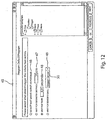
- FIG 12 there is shown the menu portion 45 which will appear on the display screen of the user interface if icon 36 (trigger) is pressed on the menu portion shown in figure 10(a) .
- various parameters defining the triggering of the tool during the pick-up operation can be specified.
- Four such trigger parameters are indicated by reference numerals 46, 47, 48 and 49, but it is understood that other parameters might be used too.
- Specifically 46 indicates an option where no triggering event is applied, i.e. the robot performs the operation as fast as possible.
- Reference numeral 47 indicates activation of the tool after the object has travelled a certain distance, which can be specified on the menu portion 45, and which in the example shown amounts to 10 cm after a trigger event, for instance the passage of the object through a light switch.
- the tool may be activated after the object has travelled for a given interval of time after the trigger event, where the interval can be specified on the menu portion 45 and which in the example shown amounts to 0.01 seconds.
- the tool may be provided by sensor means providing a signal to the control system of the robot, thereby activating the tool. This option is indicated by reference numeral 49 in figure 12 . It is possible to choose between different sensors and/or sensor locations as indicated by reference numeral 50.
- the next step in the programming procedure is shown in figure 13 and consists of specifying a suitable number of waypoints through which the tool of the robot shall move from an initial position to a final position and back to the initial position.
- the menu portion 51 corresponding to this step is shown in figure 13 .
- the path in space from initial to final position of the tool can be the same as the path followed by the tool on returning from the final to the initial position but different paths may also be chosen and specified if appropriate.
- the waypoints can be specified by their co-ordinates in space, for instance in the same manner as shown and described previously in connection with figure 10 .
- a 3D-mouse or similar device may be positioned at the different waypoints and the corresponding co-ordinates be entered into the control system of the robot directly from the mouse.
- the chosen number is indicated on the menu portion 51 at 53, and waypoints can be removed or added at 54 and 55.
- the two remaining programming steps of a pick-and-place operation is described, i.e. the specification of the position and triggering of the place operation of the tool at the final position and the return of the tool to the initial position.
- the specification of these steps corresponds to the specification of the initial position and triggering of the tool and the movement of the tool through a chosen number of waypoints from the initial to the final position of the tool and will hence only be described briefly in the following.
- the previously chosen position and triggering of the tool during pick up and movement from initial to final position can be retrieved from icons 35, 36 and 52.
- the position and triggering events/methods/sensor means can be specified at icons 57 and the return path from final back to initial position can be specified at icon 58.
- FIGS. 15 to 23 show a sequence of CAD images of a robot according to an embodiment of the invention displayed on the display screen of the user interface during the various programming stages of the robot.
- the actual movement of the robot - and hence its CAD-generated image on the interface screen - will in this case take place by actually leading the physical robot through the various steps performed during programming of the robot.
- the robot might be controlled in a manner corresponding to that described previously in connection with figures 7 to 14 .
- this sequence of movements of the robot means and procedures for controlling the pick up of an object by the tool of the robot will be described specifically in connection with figure 18 .
- FIG 15 there is thus shown a screen image of an opening page 61 of the programming wizard according to this embodiment of the user interface of the present invention.
- the page comprises a menu portion 62 and an image (CAD representation) of a robot 63 according to one embodiment of the invention.
- the robot 63 is provided with a gripper tool 64 and two cameras 65 used (among other things) for specifying the object to be gripped and handled by the robot.
- the following series of figures again relate to a pick-and-place operation, but it is understood that numerous other operations could also be programmed using this embodiment of a wizard according to the invention.
- the kind of operation is specified on the menu portion 62, in the shown example comprising two operations: (1) place and (2) pick and place. The latter is chosen as mentioned.
- FIG 16 there is shown the page 66 presented to the user during the programming operation.
- the user specifies whether the object is to be picked up based on position, colour or sensor activated position. The colour option is chosen as indicated by the arrow.
- the next page 68 shown during the programming operation comprising the user indication of the region 70 within which objects are to be picked up.
- this region 70 is specified by actually leading the tool of the robot along the entire boundary of the region. Alternatively it might be sufficient to define the region 70 by a limited number of distinct points, for instance the corners c1, c2, c3 and c4 of the region 70. This might suffice in case of pick-up regions of simple geometry.
- the text at 69 actually reads.
- FIG 18 there is shown the next page 71 used in a first step in an object identification method according to the invention.
- the tool of the robot is elevated above the defined pick-up region 70 to such an elevation that the whole pick-up region can be seen on the picture 73 recorded by means of at least one of the cameras 65 placed adjacent the tool 64, a portion of which can be seen in the picture 73 together with the picture 74' of the object 74.
- FIG 19 there is shown the next page 75 presented to the user and comprising the next step of the object identification or segmentation method according to this embodiment of the invention.
- the text at 76 reads in translation: "Choose a segmentation method that results in the whole object - and only the object - being coloured blue. [Continue>]". Different such methods could be applied but a specific method (“Method 2") is chosen as indicated by the arrow in the field 77 on page 75.
- the page 75 furthermore comprises the picture 73 recorded by the at least one camera 65 with the picture of the object 74 as recorded by the camera.
- a second picture field 78 (“Segmented picture") is shown on page 75 containing a segmented version 79 of the object.
- Segmentation methods used in the invention could be based on blob-detection algorithms known from various image processing applications, according to which "blobs" in an image, i.e. areas whose luminosity is above or below a particular value, for instance the value of the adjacent portions of the image, are identified..
- a segmented picture of the object 74 i.e. a picture of the object after image processing can be shown on the second picture field 78, in figure 19 indicated by reference numeral 79.
- segmentation can take place by clicking on a point (pixel) on the unprocessed image 74' of the object 74, i.e. the object which must be recognised by the robot system or alternatively on the surrounding portions 81 of the picture 73.
- the object could for instance be a brown piece of chocolate and the surroundings a conveyor belt of a different colour. Clicking on the picture 74' of the object 74 results in the display of a processed version 79 of the object. If the user decides that the processing has not been able to identify (distinguish the object sufficiently well from the surroundings), the user may click on another point (pixel) of the unprocessed picture 74 of the object and thereby attain a more satisfactory segmentation of the object. Various other parameters of the segmentation process may also be adjusted from the user interface. After successful segmentation, the algorithm running the image processing can store information relating to the shape of the picture of the object and use this information for later recognition of objects by the robot control system.
- FIG 20 there is shown the page 82 corresponding to the next step in the programming operation, i.e, the step of specifying the movement of the too! in space from the initial pick-up point (I) to the final (placement) point (II).
- reference numeral 83 in translation: "Now pull the robot from the pick-up area to the place area. [Continue>]"
- the user is now instructed to lead the physical robot (tool) through the desired path 84 in space and this path can either be recorded and stored in its entirety in the control system of the robot or a number of specific waypoints along the path can alternatively be recorded and stored.
- FIG 21 there is shown the page 85 corresponding to the placement operation in the pick-and-place operation.
- reference numeral 86 in translation: "Must the object be placed based on: Position; Colour; Sensor activated position", the user is asked to indicate whether the objects are to be placed based on position, colour or a sensor-activated position.
- the position option is chosen as indicated by the arrow.
- FIG 22 there is shown the page 87 used for user specification of the positions 89, at which objects are to be placed during the placement operation.
- reference numeral 88 in translation: "Pull the robot around to those positions where it must place objects" [Continue>]
- the user is instructed to lead the robot (tool) to those positions 89, where objects are to be placed.
- the co-ordinates of the position are loaded into the control system of the robot.
- Alternative procedures for indicating the placement positions to the control system of the robot could also be used.
- the "pallet” option mentioned previously according to which corners, number of rows and columns or a pattern of positions are specified could be used as an alternative.
- FIG 23 there is shown the last page 90 of the programming wizard according to this embodiment of the invention.
- reference numeral 91 in translation: "Task definition completed. Press continue in order to carry out slow test of the program. [Continue>])
- the programming of the robot is finished and a slow control and supervision operation of the robot can be performed by pressing icon 92 on page 90.
- the user interface comprises 3D graphical display means for showing a graphical 3D representation of the robot and optionally also its surroundings.
- the 3D representation of the robot moves during programming and optionally also during actual operation of the robot on the display, which greatly facilitates programming of the robot, also taking the risk of collision of robot parts with the surroundings into account.
- programming of the robot is greatly facilitated by the use of wizards as already described and these wizards can according to the invention comprise stored templates corresponding to specific operations, which templates can be pre-programmed in the control system or user interface of the robot.
- a person skilled in the art of robot programming can create and store templates in the robot system or interface according to the invention with the effect that a user, lacking routine in robot programming, can program the robot to carry out even quite complicated tasks, without the user being forced to make more choices during programming of the robot than absolutely necessary. This makes programming quicker and easier and shortens the time needed for an inexperienced user to familiarise himself with and actually carry out the programming of the robot.
- the user has a choice between a 3D representation of the robot on the display of the user interface (to give an overview of the operation of the robot) and the display of actual parameter values, co-ordinates etc. at a given instance of the operation.
- a 3D representation may also comprise the surroundings of the robot.
- the ability according to the invention to shift between 3D representations of the robot and surroundings and sets of actual parameter values, co-ordinates, etc. greatly facilitates programming and optimisation of the movement of the robot, which - possibly together with the above-mentioned pre-programmed templates - makes programming and operation of the robot according to the invention very easy even for an inexperienced person.
- the robot itself may also by use of the above mentioned encoding and controlling means 24 in the joints of the robot and/or additional sensors provided on the robot be used for programming the robot, i.e. for specifying the path of movement in space of the tool mounted on the robot and/or other parts of the robot, without the necessity to calibrate the system, as the robot uses the same sensors, encoders, etc. to indicate the position, the user wishes to define and to actually bring the robot to the desired position.
- the robot itself via the sensors, encoders, etc.
- objects in the surroundings such as objects to be picked up or obstacles to be avoided, can be specified with the robot. For a person not familiar with robot control via an interface this may be an intuitively preferred way of programming the robot.
- the execution of the program attained and stored in this manner may afterwards be monitored on the display on the user interface and modified if required.
- a first, rough programming of the robot can be performed using the robot itself followed by a finer, detailed adjustment of the programming, which may result in a faster and even more optimal programming of the robot, in particular when programming is performed by an inexperienced user.
- FIG 24 there is shown a further embodiment of a screen image of a user interface according to the invention.
- the image shows both a 3D graphical representation 111 of a robot 112 according to an embodiment of the invention and a list of program steps 113 corresponding to a virtual or actual operation (movement through waypoints and actions to be performed at different steps during the execution of the program) of the robot.
- On the 3D representation there is shown the path of movement 114 of the outermost portion/tool 116 of the robot 112 through a sequence of waypoints 115 (a total of seven waypoints are mentioned in the list of program steps 113, one of these being hidden behind the robot in the graphical representation).
- the step "action" in the list of steps 113 triggers a specific action of the tool that is carried out when the tool arrives at a specific waypoint (for instance that a voltage is applied to one of the digital output channels of the robot system, which causes the activation of a spray nozzle on the tool, spraying for instance paint on an object. In this manner it is possible to indicate the point on the path of movement 114 at which spraying is to begin).
- the shadow image 117 of the robot corresponds to the waypoint indicated by 118 in figure 24 .
- the shadow image of the robot indicates the virtual movement of the robot and the virtual position of the robot at the different waypoints, thereby giving the user an indication of how the different parts (joints, arm sections and tool) of the real robot will be located in real space, when the tool is positioned in a specific waypoint.
- a user may for instance decide whether there is a risk of collision of portions of the robot with objects in the surroundings and whether modifications of the path of movement of different portions of the robot may be required in order to ascertain that no collisions occur during real operation of the robot.
- FIG 25 there is shown another screen image on the user interface according to the invention comprising a 3D representation 119 of the robot, a field 120 specifying movements of the tool (different movements of the tool being accomplished by pressing the icons 121, 122, 123, 124 and 125).
- a field 120 specifying movements of the tool (different movements of the tool being accomplished by pressing the icons 121, 122, 123, 124 and 125).
- the manipulations of the tool by means of icons 121 to 125 take place in relation to the same point of view as the 3D representation indicated by reference numeral 119 in figure 25 .
- the screen image comprises a field 122 ("Move joints"), by means of which the user may move (rotate) each specific joint separately instead of moving the tool (field 120), where movement of the tool normally results in more than one joint moving (rotating) simultaneously.
- a field 122 "Move joints"
- the numerical values 126 could indicate the relative rotation of each specific joint or the relative rotation of the base joint (in radians or degrees), but other indications could be used and are at any rate not of prime importance for an average used. The indications may be omitted altogether, if desired.
- the position of the tool in XYZ-coordinates is indicated at 127.
- Icons referred to by 128, 129 and 130 enable a choice of different configuration spaces.
- the robot can arrive at one and the same position and orientation (pose) of the tool in a number of different manners.
- the robot according to this embodiment of the invention have eight different manners in which a given pose of the toll can be attained.
- the elbow portion of the robot may face either upwards or downwards.
- the shoulder portion may also be turned 180 degrees and the wrist may also be turned such that the "hand" faces the base of the robot.
- each joint has only one degree of freedom - rotation about an axis through the joint - and the connections of the joint with the connecting members are provided at an angle of 90 degrees relative to each other.
- FIG 26 there is shown a first embodiment of a six-axis robot according to the invention having the above characteristics.
- the robot comprises the axes A1 through A6.
- This robot has the cinematic structure: Roll-Pitch-Pitch-Pitch-Roll-Yaw and comprises only two types of joints, three of each type, two types of connecting members in the form of tubes with thin walls, one angle member and one foot member.
- FIG 27 there is shown a second embodiment of a six-axis robot according to the invention having the above characteristics.
- the robot comprises the axes A1 through A6.
- This robot has the following cinematic structure: Roll-Pitch-Pitch-Roll-Pitch-Roll and comprises three types of joints, two of each type, two types of connecting members in the form of tubes with thin walls, each comprising a corresponding adapter flange and a foot member.
- FIG 28 there is shown a cross sectional view through a joint according to an embodiment of the invention.
- the joint comprises mechanical, electro-mechanical, electronic and optical elements that are mutually interconnected, either directly via electrical connectors or via wireless, for instance optical, coupling to other elements.
- PCB printed circuit board 131
- optical encoders 132, 133 are used and a safety brake 134, 135 is implemented using a very small solenoid 134.
- the brake is designed such that the solenoid 134 can activate and deactivate the brake with a very limited force.
- the encoder 133 used for determining the position (angular orientation of the axle/rotor) of the motor (angular orientation) is mounted at the rear surface of the PCB 131.
- the motor shown in figure 28 comprises a stator part 136 and a rotor part 137.
- the encoder 132 used for determining the angular orientation of the output axle 138 or output flange 139 of the joint is mounted on the front surface of the PCB or in a socket on the front surface of the PCB 131.
- a high resolution encoder is used and the short distance between the hollow axle 138 and the encoder is important in order to attain a proper positioning of sensor and encoder disc relative to each other.
- the encoder disc 140 is mounted on the hollow axle 138 through which electrical and pneumatical connections 141 are guided through the joint and the hollow axle 138 is connected to the output flange 139.
- the safety brake 134, 135, which stops the robot 137 for instance at power drop-out, is formed as an integral part with the PCB 131.
- the solenoid 134 which in the event of power drop-out displaces a ratchet 142 into engagement with an annular member 135 mounted on the motor axle 143, is mounted directly on the PCB 131.
- This annular member 135 (friction ring) can rotate relative to the motor axle, but there is a high friction between the annular member and the motor axle 143. This ensures a controlled halt of the joint but without halting the joint so abruptly that the robot arm becomes overloaded.
- friction between the annular member 135 and the motor axle 143 is ensured by O-rings 144 tightly fitted between the motor axle 143 and the annular member 135 (friction ring).
- the joint according to this embodiment of the invention is designed such that adjacent joints can be attached to each other without use of further elements. Attachment of the joint to an adjacent joint or connecting member (for instance a thin-walled tube) takes place via the output flange 139 and the connecting portion 145 on the housing 146 of the joint.
- robot joints according to the invention can be coupled together by suitable members, for instance thin-walled tubes, which constitutes a preferred choice due to their optimal rigidity/weight ratio.
- the joint according to this embodiment of the invention comprises a seal 147 between the housing 146 and the output flange 139, main bearings 148 resting against inclined inner surface portions (bearing surfaces) 155 provided in the housing 146, sealed bearings 149, transmission 150, at least one passage 151 for connections from an adjacent joint or connecting member, an area/space (152) for a slip ring and for twisting wires 141, when the output members 138, 139 rotate, further bearings 153 and a plate 154, for instance of aluminium or other suitable material, for mounting the PCB 131 and also for acting as a heat sink for power electronics in the joint.
- a single four point of contact ball bearing or a single crossed roller bearing or a pair of angular contact ball bearings could be used.
- eccentric gear arrangement with a single eccentric pinion
- eccentric gear arrangement with 2 pinions, phaseshifted 180 degrees, or 3 pinions, phase shifted 120 degrees
- a harmonic drive gear can be used in the unit, either with or without an integrated output bearing.
Claims (6)
- Système de robot programmable comprenant:(a) un robot comprenant un nombre de sections de bras individuels, où des sections adjacentes sont interconnectées par un joint;(b) des moyens d'entraînement contrôlable fournis dans au moins certains desdits joints, et qui entraînent lesdits joints;(c) un système de contrôle pour contrôler chacun desdits moyens d'entraînement contrôlables,(d) des moyens d'interface comprenant des moyens pour programmer le système de robot, lesdits moyens d'interface utilisateur étant fournis de manière externe au robot comme une commande à distance; et(e) des moyens de mise en mémoire qui coopèrent avec lesdits moyens d'interface utilisateur et avec ledit système de contrôle pour mémoriser de l'information en relation avec le mouvement et les opérations ultérieures du robot et/ou d'un outil de robot monté sur le robot;caractérisé en ce que lesdits moyens d'interface utilisateur comprennent un écran tactile sur lequel une représentation en 3D (119) du robot est montrée avec un champ (120) qui spécifiant les mouvements du robot et/ou de l'outil par moyens de flèches icônes (121, 122, 123, 124, 125) de manière à ce que des mouvements différents du robot et/ou de l'outil peuvent être accomplis en pressant sur les flèches icônes (121, 122, 123, 124, 125) afin de changer la position et l'orientation du robot ou de l'outil du robot, en ce que les manipulations du robot et/ou de l'outil par moyens de flèches icônes (121, 122, 123, 124, 125) prennent lieux en relation au même point de vue que la représentation en 3D (119) et en ce que le positionnement et l'orientation des mouvements du robot dirigés par un utilisateur avec les flèches icônes (121, 122, 123, 124, 125) sur l'écran tactile de la commande à distance sont montrés par la représentation en 3D (119) du robot sur l'écran tactile.
- Système de robot programmable selon la revendication 1, dans lequel ledit écran tactile affiche en outre des icônes pour tourner les joints respectifs du robot.
- Système de robot programmable selon l'une des revendications 1 ou 2, caractérisé en ce que ledit système de contrôle comprend des moyens pour contrôler le déclenchement d'actions effectuées par le robot et/ou un outil monté sur le robot, où lesdits moyens de déclenchement comprennent des moyens externes sensoriels pour le placement sur des portions du robot et/ou sur des entités externes dans les environs.
- Commande à distance pour un robot programmable, qui est externe par rapport au robot programmable comprenant:(a) un écran tactile qui montre des menus en relation avec les étapes de programmation à être effectuer par un utilisateur pendant la programmation dudit robot et une représentation tridimensionnelle générée par ordinateur (119) du robot montrant le robot au moins pendant la programmation du robot; et(b) des moyens pour faire entrer des instructions à un système de contrôle du robot programmable,caractérisé en ce que la représentation en 3D (119) du robot est montrée sur ledit écran tactile avec un champ (120) qui spécifie les mouvements du robot et/ou de l'outil par moyens de flèches icônes (121, 122, 123, 124, 125) de manière à ce que des mouvements différents du robot et/ou de l'outil peuvent être accomplis en pressant sur les flèches icônes (121, 122, 123, 124, 125) afin de changer la position et l'orientation du robot ou de l'outil du robot, en ce que les manipulations du robot et/ou de l'outil par moyens de flèches icônes (121, 122, 123, 124, 125) prennent lieux en relation au même point de vue que la représentation en 3D (119) et en ce que le positionnement et l'orientation des mouvements du robot dirigés par un utilisateur avec les flèches icônes (121, 122, 123, 124, 125) sur l'écran tactile de la commande à distance sont montrés par la représentation en 3D (119) du robot sur l'écran tactile.
- Commande à distance selon la revendication 4, dans laquelle ledit écran tactile affiche en outre des icônes pour tourner les joints respectifs du robot.
- Commande à distance selon l'une des revendications 4 ou 5, caractérisée en ce qu'elle comprend en outre des moyens de mémorisation, soit dans les moyens d'interface ou connectée de manière opérationnelle aux moyens d'interface pour mémoriser de l'information par rapport à la programmation et les opérations du robot et facultativement aussi pour mémoriser de l'information par rapport aux environs du robot, tel que des obstacles à être évités pendant le mouvement du robot et/ou des régions interdites dans l'espace.
Priority Applications (3)
| Application Number | Priority Date | Filing Date | Title |
|---|---|---|---|
| EP16154439.0A EP3045273B1 (fr) | 2006-03-03 | 2007-03-02 | Joint pour un robot |
| EP18211415.7A EP3530420B1 (fr) | 2006-03-03 | 2007-03-02 | Joint pour un robot |
| DK16154439.0T DK3045273T3 (en) | 2006-03-03 | 2007-03-02 | Joint for a robot |
Applications Claiming Priority (2)
| Application Number | Priority Date | Filing Date | Title |
|---|---|---|---|
| DKPA200600308 | 2006-03-03 | ||
| PCT/IB2007/050683 WO2007099511A2 (fr) | 2006-03-03 | 2007-03-02 | Robot programmable et interface utilisateur |
Related Child Applications (3)
| Application Number | Title | Priority Date | Filing Date |
|---|---|---|---|
| EP16154439.0A Division EP3045273B1 (fr) | 2006-03-03 | 2007-03-02 | Joint pour un robot |
| EP16154439.0A Division-Into EP3045273B1 (fr) | 2006-03-03 | 2007-03-02 | Joint pour un robot |
| EP18211415.7A Division EP3530420B1 (fr) | 2006-03-03 | 2007-03-02 | Joint pour un robot |
Publications (2)
| Publication Number | Publication Date |
|---|---|
| EP1996376A2 EP1996376A2 (fr) | 2008-12-03 |
| EP1996376B1 true EP1996376B1 (fr) | 2016-05-11 |
Family
ID=38445804
Family Applications (3)
| Application Number | Title | Priority Date | Filing Date |
|---|---|---|---|
| EP16154439.0A Active EP3045273B1 (fr) | 2006-03-03 | 2007-03-02 | Joint pour un robot |
| EP18211415.7A Active EP3530420B1 (fr) | 2006-03-03 | 2007-03-02 | Joint pour un robot |
| EP07735028.8A Active EP1996376B1 (fr) | 2006-03-03 | 2007-03-02 | Robot programmable et interface utilisateur |
Family Applications Before (2)
| Application Number | Title | Priority Date | Filing Date |
|---|---|---|---|
| EP16154439.0A Active EP3045273B1 (fr) | 2006-03-03 | 2007-03-02 | Joint pour un robot |
| EP18211415.7A Active EP3530420B1 (fr) | 2006-03-03 | 2007-03-02 | Joint pour un robot |
Country Status (7)
| Country | Link |
|---|---|
| US (3) | US8779715B2 (fr) |
| EP (3) | EP3045273B1 (fr) |
| CA (1) | CA2644614C (fr) |
| DK (2) | DK3045273T3 (fr) |
| ES (3) | ES2590078T3 (fr) |
| PL (2) | PL1996376T3 (fr) |
| WO (1) | WO2007099511A2 (fr) |
Cited By (2)
| Publication number | Priority date | Publication date | Assignee | Title |
|---|---|---|---|---|
| US11218054B2 (en) | 2019-03-28 | 2022-01-04 | Nidec Motor Corporation | Motor with rotation sensor |
| DE102021205491A1 (de) | 2021-05-31 | 2022-12-01 | Robert Bosch Gesellschaft mit beschränkter Haftung | Verfahren zum Einstellen eines linearen Mehrachssystems und lineares Mehrachssystem |
Families Citing this family (152)
| Publication number | Priority date | Publication date | Assignee | Title |
|---|---|---|---|---|
| US10219815B2 (en) | 2005-09-22 | 2019-03-05 | The Regents Of The University Of Michigan | Histotripsy for thrombolysis |
| JP4737160B2 (ja) * | 2007-07-31 | 2011-07-27 | トヨタ自動車株式会社 | パワーアシスト装置およびその制御方法 |
| WO2009049682A1 (fr) * | 2007-10-19 | 2009-04-23 | Abb Technology Ab | Robot industriel conduisant une machine et procédé de commande d'un robot industriel conduisant une machine |
| US20090248200A1 (en) * | 2007-10-22 | 2009-10-01 | North End Technologies | Method & apparatus for remotely operating a robotic device linked to a communications network |
| FR2926240B1 (fr) * | 2008-01-15 | 2010-04-30 | Blm | Procede pour l'apprentissage d'un robot ou similaire et dispositif pour la mise en oeuvre de ce procede. |
| CN101737603B (zh) * | 2008-11-10 | 2011-11-30 | 鸿富锦精密工业(深圳)有限公司 | 万向关节 |
| WO2010118769A1 (fr) | 2009-04-15 | 2010-10-21 | Abb Research Ltd | Appareil pour bras de robot |
| DE102010004476A1 (de) * | 2010-01-13 | 2011-07-14 | KUKA Laboratories GmbH, 86165 | Verfahren und Vorrichtung zum Kontrollieren einer Roboterapplikation |
| DE102010012598A1 (de) * | 2010-02-26 | 2011-09-01 | Kuka Laboratories Gmbh | Prozessmodulbibliothek und Programmierumgebung zur Programmierung eines Manipulatorprozesses |
| US9104202B2 (en) | 2010-05-11 | 2015-08-11 | Irobot Corporation | Remote vehicle missions and systems for supporting remote vehicle missions |
| US9002535B2 (en) * | 2010-05-11 | 2015-04-07 | Irobot Corporation | Navigation portals for a remote vehicle control user interface |
| US9020644B2 (en) * | 2010-08-11 | 2015-04-28 | Barrett Technology, Inc. | Pistol-grip for intuitive control of a robotic or virtual hand |
| EP2453325A1 (fr) | 2010-11-16 | 2012-05-16 | Universal Robots ApS | Procédé et support de commande d'un robot |
| DE102010063222B4 (de) * | 2010-12-16 | 2019-02-14 | Robert Bosch Gmbh | Einrichtung und Verfahren zur Programmierung einer Handhabungsvorrichtung sowie Handhabungsvorrichtung |
| JP5849403B2 (ja) * | 2011-02-15 | 2016-01-27 | セイコーエプソン株式会社 | ロボットコントローラー、ロボット、及び、ロボットシステム |
| US9815193B2 (en) * | 2011-06-27 | 2017-11-14 | Delaware Capital Formation, Inc. | Electric motor based holding control systems and methods |
| DE102012108418A1 (de) | 2011-09-14 | 2013-03-14 | Robotics Technology Leaders Gmbh | Vorrichtung zur sicheren Kollaboration zwischen Mensch und Roboter |
| JP5561260B2 (ja) * | 2011-09-15 | 2014-07-30 | 株式会社安川電機 | ロボットシステム及び撮像方法 |
| DK2796249T3 (en) | 2011-09-28 | 2016-03-07 | Universal Robots As | Programming robots |
| US9415509B2 (en) | 2011-11-04 | 2016-08-16 | Fanuc America Corporation | Robot teach device with 3-D display |
| US9044857B2 (en) | 2012-02-14 | 2015-06-02 | Jerry Neal Sommerville | Control system that guides a robot or articulated device with a laser distance meter for 3D motion, or guides a robot or articulated device with a computer pointing device (such as a mouse) for 2D motion |
| DE102012102749A1 (de) * | 2012-03-29 | 2013-10-02 | Reis Group Holding Gmbh & Co. Kg | Vorrichtung und Verfahren zur Bedienung eines Industrieroboters |
| DE102012103032B3 (de) * | 2012-04-05 | 2013-07-04 | Reis Group Holding Gmbh & Co. Kg | Verfahren zur Bedienung eines Industrieroboters |
| DE102012103031A1 (de) * | 2012-04-05 | 2013-10-10 | Reis Group Holding Gmbh & Co. Kg | Verfahren zur Bedienung eines Industrieroboters |
| DE102012013022A1 (de) * | 2012-06-29 | 2014-04-24 | Liebherr-Verzahntechnik Gmbh | Vorrichtung zur automatisierten Handhabung von Werkstücken |
| CN102773858B (zh) * | 2012-07-17 | 2015-06-03 | 北京航空航天大学 | 一种码垛机器人的避障方法 |
| JP5642304B2 (ja) * | 2013-02-15 | 2014-12-17 | 株式会社神戸製鋼所 | ロボットペンダント |
| JP5672326B2 (ja) * | 2013-03-19 | 2015-02-18 | 株式会社安川電機 | ロボットシステム |
| WO2015003154A1 (fr) | 2013-07-03 | 2015-01-08 | Histosonics, Inc. | Limiteur de bras d'articulation pour un système de traitement par cavitation aux ultrasons |
| KR20160018672A (ko) * | 2013-07-09 | 2016-02-17 | 가부시키가이샤 야스카와덴키 | 로봇 및 로봇의 관절 기구 |
| JP5939213B2 (ja) * | 2013-08-09 | 2016-06-22 | 株式会社安川電機 | ロボット制御装置及びロボット制御方法 |
| US10780298B2 (en) | 2013-08-22 | 2020-09-22 | The Regents Of The University Of Michigan | Histotripsy using very short monopolar ultrasound pulses |
| US20150090055A1 (en) * | 2013-09-30 | 2015-04-02 | GOJO Industries, Inc., | Universal mounting assembly for sensing device |
| DE102013019869B4 (de) * | 2013-11-28 | 2022-01-13 | Abb Schweiz Ag | Roboterarm mit Eingabemodul |
| SG11201607059UA (en) | 2014-03-04 | 2016-09-29 | Universal Robots As | Safety system for industrial robot |
| US9701018B2 (en) | 2014-04-01 | 2017-07-11 | Bot & Dolly, Llc | Software interface for authoring robotic manufacturing process |
| US9841749B2 (en) * | 2014-04-01 | 2017-12-12 | Bot & Dolly, Llc | Runtime controller for robotic manufacturing system |
| US9278449B1 (en) | 2014-05-21 | 2016-03-08 | Bot & Dolly, Llc | Closed-loop control system for robotic operation |
| US9555545B2 (en) | 2014-05-21 | 2017-01-31 | Bot & Dolly, Llc | Systems and methods for time-based parallel robotic operation |
| US9308647B2 (en) | 2014-06-03 | 2016-04-12 | Bot & Dolly, Llc | Systems and methods for instructing robotic operation |
| DE102015204641B4 (de) * | 2014-06-03 | 2021-03-25 | ArtiMinds Robotics GmbH | Verfahren und System zur Programmierung eines Roboters |
| EP2965873B1 (fr) * | 2014-07-10 | 2020-10-07 | Siemens Aktiengesellschaft | Procédé de commande automatique d'un manipulateur |
| US10583569B2 (en) * | 2014-08-08 | 2020-03-10 | Valuebiotech S.R.L. | Articulated device for robotic systems |
| DE102014219077A1 (de) * | 2014-09-22 | 2016-03-24 | Siemens Aktiengesellschaft | Mobiles medizinisches Gerät |
| JP5898743B1 (ja) * | 2014-09-25 | 2016-04-06 | 上銀科技股▲分▼有限公司 | 関節式ロボットアームの手首構造 |
| JP6678648B2 (ja) | 2014-09-26 | 2020-04-08 | テラダイン、 インコーポレイテッド | グリッパと自動試験装置 |
| JP6497021B2 (ja) * | 2014-10-01 | 2019-04-10 | 株式会社デンソーウェーブ | ロボット操作装置、ロボットシステム、及びロボット操作プログラム |
| CN105626722B (zh) * | 2014-11-05 | 2018-02-09 | 广明光电股份有限公司 | 机器手臂的刹车装置 |
| CN104444351B (zh) * | 2014-11-07 | 2016-11-02 | 京东方科技集团股份有限公司 | 机械手臂及基板拾取装置 |
| US10635082B2 (en) * | 2014-12-26 | 2020-04-28 | Kawasaki Jukogyo Kabushiki Kaisha | Robot motion program generating method and robot motion program generating apparatus |
| JP6545195B2 (ja) * | 2015-01-09 | 2019-07-17 | 第一電通株式会社 | 工作装置 |
| US9857962B2 (en) * | 2015-03-19 | 2018-01-02 | Denso Wave Incorporated | Robot operation apparatus and robot operation program product |
| US10048851B2 (en) * | 2015-03-19 | 2018-08-14 | Denso Wave Incorporated | Apparatus for operating robots |
| JP6631279B2 (ja) * | 2015-03-19 | 2020-01-15 | 株式会社デンソーウェーブ | ロボット操作装置、ロボット操作プログラム |
| KR101627519B1 (ko) * | 2015-05-04 | 2016-06-08 | 재단법인대구경북과학기술원 | 로봇 원격 제어 장치 및 그 방법 |
| JP6900533B2 (ja) * | 2015-05-12 | 2021-07-07 | キヤノン株式会社 | 情報処理方法、情報処理装置、ロボット装置、情報処理プログラム、およびコンピュータ読み取り可能な記録媒体 |
| JP6676286B2 (ja) * | 2015-05-12 | 2020-04-08 | キヤノン株式会社 | 情報処理方法、および情報処理装置 |
| US9687982B1 (en) | 2015-05-27 | 2017-06-27 | X Development Llc | Adapting programming of a robot and/or control of the robot based on one or more parameters of an end effector of the robot |
| US9707680B1 (en) | 2015-05-28 | 2017-07-18 | X Development Llc | Suggesting, selecting, and applying task-level movement parameters to implementation of robot motion primitives |
| US9895803B1 (en) | 2015-06-19 | 2018-02-20 | X Development Llc | Calculating trajectory corridor for robot end effector |
| WO2016210133A1 (fr) | 2015-06-24 | 2016-12-29 | The Regents Of The Universtiy Of Michigan | Systèmes et procédés de thérapie par histotripsie pour le traitement de tissu cérébral |
| US10850393B2 (en) | 2015-07-08 | 2020-12-01 | Universal Robots A/S | Method for extending end user programming of an industrial robot with third party contributions |
| DE202015009617U1 (de) | 2015-08-14 | 2018-08-30 | Franka Emika Gmbh | Robotersystem und Gehäuseteil für ein solches Robotersystem |
| DE102015113467A1 (de) | 2015-08-14 | 2017-02-16 | Sami Haddadin | Roboterarm und Roboterhandgelenk |
| JP6791859B2 (ja) * | 2015-09-11 | 2020-11-25 | ライフロボティクス株式会社 | ロボット装置 |
| KR20180015774A (ko) * | 2015-09-25 | 2018-02-14 | 두산로보틱스 주식회사 | 로봇 제어 방법 및 장치 |
| DE102015116609A1 (de) | 2015-09-30 | 2017-03-30 | Sami Haddadin | Gelenkeinrichtung |
| DE102015012959B4 (de) | 2015-10-08 | 2019-01-17 | Franka Emika Gmbh | Robotersystem und Verfahren zur Steuerung eines Robotersystems |
| DE102015117211B8 (de) | 2015-10-08 | 2016-12-29 | Kastanienbaum GmbH | Roboterarm mit Eingabeelementen |
| DE102015012962A1 (de) * | 2015-10-08 | 2017-04-13 | Sami Haddadin | Robotersystem |
| DE102015012961B4 (de) * | 2015-10-08 | 2022-05-05 | Kastanienbaum GmbH | Robotersystem |
| TWI684502B (zh) * | 2016-01-18 | 2020-02-11 | 廣明光電股份有限公司 | 機器手臂解除剎車的方法(一) |
| JP6684439B2 (ja) | 2016-03-30 | 2020-04-22 | 日本電産株式会社 | ロボット |
| JP6610477B2 (ja) | 2016-03-30 | 2019-11-27 | 日本電産株式会社 | 回転アクチュエータおよびロボット |
| JP6708953B2 (ja) | 2016-03-30 | 2020-06-10 | 日本電産株式会社 | ロボット |
| TWI805545B (zh) | 2016-04-12 | 2023-06-21 | 丹麥商環球機器人公司 | 用於藉由示範來程式化機器人之方法和電腦程式產品 |
| DE102016004810B3 (de) * | 2016-04-20 | 2017-06-14 | Sami Haddadin | Antriebsvorrichtung für einen Manipulator |
| DE102016004788A1 (de) | 2016-04-20 | 2017-10-26 | Kastanienbaum GmbH | Verfahren zur Herstellung eines Roboters und Vorrichtung zur Durchführung dieses Verfahrens |
| DE102016004787B4 (de) * | 2016-04-20 | 2023-02-02 | Franka Emika Gmbh | Antriebsvorrichtung für einen Roboter und Verfahren zu ihrer Herstellung |
| LU93047B1 (de) | 2016-04-27 | 2017-11-07 | Ovalo Gmbh | Motorisiertes Gelenk für einen programmierbaren Bewegungsautomaten |
| LU93045B1 (de) | 2016-04-27 | 2017-11-07 | Ovalo Gmbh | Motorisiertes Gelenk für einen programmierbaren Bewegungsautomaten |
| LU93043B1 (de) | 2016-04-27 | 2017-11-07 | Ovalo Gmbh | Motorisiertes Gelenk für einen programmierbaren Bewegungsautomaten |
| LU93044B1 (de) | 2016-04-27 | 2017-11-07 | Ovalo Gmbh | Motorisiertes Gelenk für einen programmierbaren Bewegungsautomaten |
| LU93046B1 (de) | 2016-04-27 | 2017-11-07 | Ovalo Gmbh | Motorisiertes Gelenk für einen programmierbaren Bewegungsautomaten |
| CN107443389B (zh) * | 2016-05-31 | 2019-12-31 | 发那科株式会社 | 机器人控制装置及机器人控制方法 |
| JP6833352B2 (ja) * | 2016-06-09 | 2021-02-24 | キヤノン株式会社 | 無線通信装置及び機器 |
| KR101898092B1 (ko) * | 2016-06-17 | 2018-09-12 | 주식회사 뉴로메카 | 다자유도 로봇의 말단 제어를 위한 콘트롤러, 상기 콘트롤러를 이용한 다자유도 로봇 제어방법 및 이에 의해 동작하는 로봇 |
| US10265862B1 (en) * | 2016-06-21 | 2019-04-23 | University Of South Florida | Robotic end effectors for use with robotic manipulators |
| US10414046B1 (en) * | 2016-11-07 | 2019-09-17 | X Development Llc | Modular robot design |
| US10337561B2 (en) | 2016-12-15 | 2019-07-02 | Boston Dynamics, Inc. | Transmission with integrated overload protection for a legged robot |
| US10363635B2 (en) * | 2016-12-21 | 2019-07-30 | Amazon Technologies, Inc. | Systems for removing items from a container |
| IT201600130715A1 (it) * | 2016-12-23 | 2018-06-23 | Comau Spa | "Dispositivo funzionale, in particolare robot, a moduli componibili per uso educativo" |
| DK3348361T3 (da) | 2017-01-13 | 2022-03-21 | Universal Robots As | Fastspændt flangesamling |
| US11161258B2 (en) | 2017-01-16 | 2021-11-02 | Kollmorgen Corporation | Robot arm joint |
| US11173615B2 (en) | 2017-03-30 | 2021-11-16 | Soft Robotics, Inc. | User-assisted robotic control systems |
| JP6748019B2 (ja) | 2017-04-10 | 2020-08-26 | ファナック株式会社 | 外力表示機能を有するロボットシステム、処理装置及び教示操作盤 |
| JP7091609B2 (ja) * | 2017-04-14 | 2022-06-28 | セイコーエプソン株式会社 | シミュレーション装置、ロボット制御装置およびロボット |
| JP6880982B2 (ja) * | 2017-04-21 | 2021-06-02 | セイコーエプソン株式会社 | 制御装置およびロボットシステム |
| CN108789486A (zh) * | 2017-04-28 | 2018-11-13 | 广明光电股份有限公司 | 机器手臂解除刹车的方法 |
| CN106976104A (zh) * | 2017-05-11 | 2017-07-25 | 华志微创医疗科技(北京)有限公司 | 一种空间五自由度机械臂 |
| US11220007B2 (en) * | 2017-08-23 | 2022-01-11 | Shenzhen Dorabot Robotics Co., Ltd. | Method of stacking goods by robot, system of controlling robot to stack goods, and robot |
| US9981174B1 (en) * | 2017-10-12 | 2018-05-29 | Timothy Joseph Decilveo | Front toss machine |
| US20190126490A1 (en) * | 2017-10-26 | 2019-05-02 | Ca, Inc. | Command and control interface for collaborative robotics |
| JP7095262B2 (ja) * | 2017-11-10 | 2022-07-05 | 株式会社安川電機 | プログラミング支援装置、ロボットシステム及びプログラム生成方法 |
| KR101956617B1 (ko) * | 2017-11-23 | 2019-03-12 | (주)한국미래기술 | 병렬형 집적 구동장치 |
| JP6737764B2 (ja) * | 2017-11-24 | 2020-08-12 | ファナック株式会社 | ロボットに対して教示操作を行う教示装置 |
| JP6763846B2 (ja) | 2017-11-24 | 2020-09-30 | ファナック株式会社 | ロボットの教示操作を行う教示装置および教示方法 |
| JP7170389B2 (ja) * | 2017-11-28 | 2022-11-14 | 住友重機械工業株式会社 | ギヤモータ |
| EP3498433A1 (fr) | 2017-12-14 | 2019-06-19 | Universal Robots A/S | Trajectoires de sécurité dynamique dans un système robotisé |
| JP7069971B2 (ja) * | 2018-03-30 | 2022-05-18 | セイコーエプソン株式会社 | 制御装置、ロボット、およびロボットシステム |
| EP3793787B1 (fr) | 2018-05-18 | 2023-11-15 | Universal Robots A/S | Articulation de robot comprenant un ensemble de frein |
| DE102018004358A1 (de) * | 2018-06-02 | 2019-12-05 | Franka Emika Gmbh | Antriebsvorrichtung für einen Manipulator |
| CN112352206A (zh) | 2018-06-15 | 2021-02-09 | 优傲机器人公司 | 机器人臂的双模自由驱动 |
| WO2019238940A1 (fr) * | 2018-06-15 | 2019-12-19 | Universal Robots A/S | Estimation de charge utile fixée à un bras de robot |
| CN110815288B (zh) * | 2018-08-09 | 2022-06-21 | 达明机器人股份有限公司 | 机器手臂的刹车装置 |
| CN108890688A (zh) * | 2018-08-17 | 2018-11-27 | 上海节卡机器人科技有限公司 | 一种协作机器人一体化关节 |
| US11331814B2 (en) * | 2018-09-13 | 2022-05-17 | Kinova Inc. | Articulated mechanism with protective sleeve at joint |
| US11491644B2 (en) * | 2018-09-13 | 2022-11-08 | Kinova Inc. | Articulated mechanism with compact torque sensor |
| AU2019389001A1 (en) | 2018-11-28 | 2021-06-10 | Histosonics, Inc. | Histotripsy systems and methods |
| JP7255210B2 (ja) * | 2019-01-31 | 2023-04-11 | セイコーエプソン株式会社 | 制御装置、ロボットシステム、及び表示方法 |
| DE102019106582A1 (de) * | 2019-03-14 | 2020-09-17 | Franka Emika Gmbh | Bremsvorrichtung für eine Antriebseinrichtung eines Roboters |
| US11599128B2 (en) | 2020-04-22 | 2023-03-07 | Boston Dynamics, Inc. | Perception and fitting for a stair tracker |
| US11548151B2 (en) | 2019-04-12 | 2023-01-10 | Boston Dynamics, Inc. | Robotically negotiating stairs |
| JP7057316B2 (ja) * | 2019-04-26 | 2022-04-19 | ファナック株式会社 | ロボット |
| WO2020222735A1 (fr) | 2019-04-29 | 2020-11-05 | Google Llc | Dispositif informatique motorisé réglant de manière autonome la position et/ou l'orientation de dispositif d'interfaces selon des demandes automatisées d'assistants |
| DE102019112023B4 (de) * | 2019-05-08 | 2022-04-21 | Franka Emika Gmbh | Bremsvorrichtung für eine Antriebseinrichtung eines Roboters |
| DE102019112024B4 (de) * | 2019-05-08 | 2022-04-14 | Franka Emika Gmbh | Verfahren zur Steuerung von Bremsvorrichtungen in einem Robotersystem sowie Roboter |
| DE102019112029B4 (de) * | 2019-05-08 | 2022-04-21 | Franka Emika Gmbh | Verfahren zur Steuerung von Bremsvorrichtungen in einem Robotersystem sowie Roboter |
| DE202019102591U1 (de) | 2019-05-08 | 2019-05-29 | Franka Emika Gmbh | Bremsvorrichtung für eine Antriebseinrichtung eines Roboters |
| USD958859S1 (en) * | 2019-05-17 | 2022-07-26 | Kinova Inc. | Robotic arm |
| DE102019004478B3 (de) * | 2019-06-26 | 2020-10-29 | Franka Emlka Gmbh | System zum Vornehmen einer Eingabe an einem Robotermanipulator |
| DE102019117217B3 (de) * | 2019-06-26 | 2020-08-20 | Franka Emika Gmbh | Verfahren zum Vorgeben eines Eingabewerts an einem Robotermanipulator |
| USD915487S1 (en) | 2019-09-07 | 2021-04-06 | Universal Robots A/S | Robotic arm |
| US11254015B2 (en) | 2019-09-24 | 2022-02-22 | Thermo Crs Ltd. | Multi-axis gripper for lab automation robot |
| DE102019125957B4 (de) * | 2019-09-26 | 2021-04-29 | Franka Emika Gmbh | Bremsvorrichtung für einen Robotermanipulator |
| US11478936B2 (en) * | 2019-10-09 | 2022-10-25 | Canon Kabushiki Kaisha | Image processing apparatus that processes image picked up by image pickup apparatus attached to robot, control method therefor, and storage medium storing control program therefor |
| USD923679S1 (en) * | 2019-10-10 | 2021-06-29 | Agile Robots AG | Robot |
| US10930812B1 (en) * | 2019-11-21 | 2021-02-23 | United States Of America As Represented By The Administrator Of Nasa | Method for fabricating a photovoltaic device using computer-controlled system |
| US11813485B2 (en) | 2020-01-28 | 2023-11-14 | The Regents Of The University Of Michigan | Systems and methods for histotripsy immunosensitization |
| US11602862B2 (en) | 2020-03-11 | 2023-03-14 | Energid Technologies Corporation | Pneumatic hose assembly for a robot |
| US11797016B2 (en) | 2020-04-13 | 2023-10-24 | Boston Dynamics, Inc. | Online authoring of robot autonomy applications |
| USD985642S1 (en) * | 2020-04-29 | 2023-05-09 | Agile Robots AG | Robotic arm |
| US20210379770A1 (en) * | 2020-06-09 | 2021-12-09 | Christian Academy of Knoxville | Attachment system for robotics and power tools |
| CN111890410A (zh) * | 2020-07-01 | 2020-11-06 | 北京工业大学 | 一种具备运行状态监测功能的驱控一体化协作机器人关节 |
| CN112857871A (zh) * | 2021-01-13 | 2021-05-28 | 广东韶钢松山股份有限公司 | 一种用于机械手的定位取样装置及方法 |
| TW202232261A (zh) * | 2021-01-14 | 2022-08-16 | 日商發那科股份有限公司 | 機器人教示裝置及機器人程式的生成用程式 |
| USD1006081S1 (en) | 2021-06-07 | 2023-11-28 | Kinova Inc. | Robotic arm |
| CN114311017A (zh) * | 2022-01-12 | 2022-04-12 | 深圳市普渡怒放科技有限公司 | 关节模块、关节模块组件及关节机器人 |
| DE102022110579A1 (de) | 2022-04-29 | 2023-11-02 | Synapticon GmbH | Motor-Antriebseinheit für einen Roboter oder ein Robotergelenk, mit Bremsfunktion |
| DE102022112242B3 (de) | 2022-05-16 | 2023-10-19 | COBOWORX GmbH | Drehsystem |
| CN114918923B (zh) * | 2022-06-20 | 2023-09-22 | 山东大学 | 一种近距人机协作环境下机械臂规避人体方法及系统 |
| CN115533961B (zh) * | 2022-11-30 | 2023-03-14 | 中国电力科学研究院有限公司 | 一种配网带电作业用协作机械臂及其装配方法 |
Citations (5)
| Publication number | Priority date | Publication date | Assignee | Title |
|---|---|---|---|---|
| US4831548A (en) * | 1985-10-23 | 1989-05-16 | Hitachi, Ltd. | Teaching apparatus for robot |
| JPH10146782A (ja) * | 1996-11-13 | 1998-06-02 | Mitsubishi Heavy Ind Ltd | ロボットの教示操作方法 |
| US5937143A (en) * | 1995-09-18 | 1999-08-10 | Fanuc, Ltd. | Teaching pendant for a robot |
| US6088628A (en) * | 1996-07-24 | 2000-07-11 | Fanuc, Ltd. | Jog feeding method for robots |
| EP1522912A2 (fr) * | 2003-10-08 | 2005-04-13 | Fanuc Ltd | Système de contrôle manuel pour robot |
Family Cites Families (31)
| Publication number | Priority date | Publication date | Assignee | Title |
|---|---|---|---|---|
| US4398110A (en) * | 1982-05-05 | 1983-08-09 | Westinghouse Electric Corp. | Harmonic electric actuator |
| JPS60163108A (ja) * | 1984-02-03 | 1985-08-26 | Hitachi Ltd | ロボツトの直接教示装置 |
| US4678952A (en) | 1985-08-13 | 1987-07-07 | Intelledex Incorporated | Sealed joint for a robot and the like |
| US5155423A (en) * | 1986-02-18 | 1992-10-13 | Robotics Research Corporation | Industrial robot with servo |
| JPS62282886A (ja) * | 1986-05-28 | 1987-12-08 | 株式会社日立製作所 | モジユ−ル型マニピユレ−タ |
| IT1245433B (it) * | 1991-03-04 | 1994-09-20 | Comau Spa | Polso di robot industriale |
| US5103941A (en) * | 1991-03-28 | 1992-04-14 | The United States Of America As Represented By The Administrator Of The National Aeronautics & Space Administration | Roller locking brake |
| US5428713A (en) * | 1991-11-25 | 1995-06-27 | Kabushiki Kaisha Toshiba | Compound module type manipulator apparatus |
| US5293107A (en) * | 1993-02-24 | 1994-03-08 | Fanuc Robotics North America, Inc. | Motorized rotary joint and method of constructing a modular robot utilizing same |
| US5495410A (en) | 1994-08-12 | 1996-02-27 | Minnesota Mining And Manufacturing Company | Lead-through robot programming system |
| US6331181B1 (en) * | 1998-12-08 | 2001-12-18 | Intuitive Surgical, Inc. | Surgical robotic tools, data architecture, and use |
| GB9713765D0 (en) * | 1997-07-01 | 1997-09-03 | Engineering Services Inc | Reconfigurable mudular drive system |
| WO2000025185A1 (fr) | 1998-10-27 | 2000-05-04 | Irobotics, Inc. | Planification de processus robotises utilisant des gabarits |
| JP3326472B2 (ja) * | 1999-11-10 | 2002-09-24 | 独立行政法人 航空宇宙技術研究所 | 多関節ロボット |
| EP1273398A4 (fr) * | 2000-02-25 | 2003-07-30 | Bandai Co | Ensemble elements destine a un robot |
| US6837892B2 (en) * | 2000-07-24 | 2005-01-04 | Mazor Surgical Technologies Ltd. | Miniature bone-mounted surgical robot |
| US6385508B1 (en) * | 2000-10-31 | 2002-05-07 | Fanuc Robotics North America, Inc. | Lead-through teach handle assembly and method of teaching a robot assembly |
| US6442451B1 (en) * | 2000-12-28 | 2002-08-27 | Robotic Workspace Technologies, Inc. | Versatile robot control system |
| JP3864370B2 (ja) * | 2001-06-27 | 2006-12-27 | 学校法人東海大学 | 歩行ロボットの関節制動装置 |
| EP1410163A1 (fr) * | 2001-06-29 | 2004-04-21 | Abb Ab | Systeme et procede pour interaction utilisateur/objets |
| US6587752B1 (en) * | 2001-12-25 | 2003-07-01 | National Institute Of Advanced Industrial Science And Technology | Robot operation teaching method and apparatus |
| US6996456B2 (en) * | 2002-10-21 | 2006-02-07 | Fsi International, Inc. | Robot with tactile sensor device |
| DE10305384A1 (de) * | 2003-02-11 | 2004-08-26 | Kuka Roboter Gmbh | Verfahren und Vorrichtung zur Visualisierung rechnergestützter Informationen |
| SE524818C2 (sv) | 2003-02-13 | 2004-10-05 | Abb Ab | En metod och ett system för att programmera en industrirobot att förflytta sig relativt definierade positioner på ett objekt |
| JP4198511B2 (ja) * | 2003-04-14 | 2008-12-17 | 三菱電機株式会社 | 動力伝達装置および動力伝達装置の制御方法 |
| US8160205B2 (en) * | 2004-04-06 | 2012-04-17 | Accuray Incorporated | Robotic arm for patient positioning assembly |
| US20060125806A1 (en) * | 2004-09-27 | 2006-06-15 | The Regents Of The University Of Minnesota | Human-activated displacement control appliance for use with computerized device/mechanism |
| JP5000893B2 (ja) * | 2005-01-27 | 2012-08-15 | 日立オートモティブシステムズ株式会社 | 電動ブレーキ制御装置及び電動ブレーキ制御方法 |
| US20060178775A1 (en) * | 2005-02-04 | 2006-08-10 | George Zhang | Accelerometer to monitor movement of a tool assembly attached to a robot end effector |
| US7643907B2 (en) * | 2005-02-10 | 2010-01-05 | Abb Research Ltd. | Method and apparatus for developing a metadata-infused software program for controlling a robot |
| EP1724676A1 (fr) * | 2005-05-20 | 2006-11-22 | ABB Research Ltd. | Procédé et dispositif pour développer d'un logiciel |
-
2007
- 2007-03-02 ES ES07735028.8T patent/ES2590078T3/es active Active
- 2007-03-02 PL PL07735028.8T patent/PL1996376T3/pl unknown
- 2007-03-02 WO PCT/IB2007/050683 patent/WO2007099511A2/fr active Application Filing
- 2007-03-02 DK DK16154439.0T patent/DK3045273T3/en active
- 2007-03-02 CA CA2644614A patent/CA2644614C/fr active Active
- 2007-03-02 EP EP16154439.0A patent/EP3045273B1/fr active Active
- 2007-03-02 EP EP18211415.7A patent/EP3530420B1/fr active Active
- 2007-03-02 ES ES16154439T patent/ES2712461T3/es active Active
- 2007-03-02 PL PL18211415.7T patent/PL3530420T3/pl unknown
- 2007-03-02 DK DK07735028.8T patent/DK1996376T3/en active
- 2007-03-02 US US12/281,528 patent/US8779715B2/en active Active
- 2007-03-02 ES ES18211415T patent/ES2963735T3/es active Active
- 2007-03-02 EP EP07735028.8A patent/EP1996376B1/fr active Active
-
2012
- 2012-03-07 US US13/414,071 patent/US8410732B2/en active Active
-
2013
- 2013-03-14 US US13/827,824 patent/US8614559B2/en active Active
Patent Citations (5)
| Publication number | Priority date | Publication date | Assignee | Title |
|---|---|---|---|---|
| US4831548A (en) * | 1985-10-23 | 1989-05-16 | Hitachi, Ltd. | Teaching apparatus for robot |
| US5937143A (en) * | 1995-09-18 | 1999-08-10 | Fanuc, Ltd. | Teaching pendant for a robot |
| US6088628A (en) * | 1996-07-24 | 2000-07-11 | Fanuc, Ltd. | Jog feeding method for robots |
| JPH10146782A (ja) * | 1996-11-13 | 1998-06-02 | Mitsubishi Heavy Ind Ltd | ロボットの教示操作方法 |
| EP1522912A2 (fr) * | 2003-10-08 | 2005-04-13 | Fanuc Ltd | Système de contrôle manuel pour robot |
Cited By (2)
| Publication number | Priority date | Publication date | Assignee | Title |
|---|---|---|---|---|
| US11218054B2 (en) | 2019-03-28 | 2022-01-04 | Nidec Motor Corporation | Motor with rotation sensor |
| DE102021205491A1 (de) | 2021-05-31 | 2022-12-01 | Robert Bosch Gesellschaft mit beschränkter Haftung | Verfahren zum Einstellen eines linearen Mehrachssystems und lineares Mehrachssystem |
Also Published As
| Publication number | Publication date |
|---|---|
| WO2007099511A2 (fr) | 2007-09-07 |
| DK3045273T3 (en) | 2019-02-25 |
| DK1996376T3 (en) | 2016-08-29 |
| CA2644614A1 (fr) | 2007-09-07 |
| US20130255426A1 (en) | 2013-10-03 |
| EP1996376A2 (fr) | 2008-12-03 |
| CA2644614C (fr) | 2015-02-03 |
| EP3045273B1 (fr) | 2018-12-12 |
| ES2712461T3 (es) | 2019-05-13 |
| US8614559B2 (en) | 2013-12-24 |
| US8779715B2 (en) | 2014-07-15 |
| PL3530420T3 (pl) | 2024-03-18 |
| EP3045273A1 (fr) | 2016-07-20 |
| PL1996376T3 (pl) | 2016-12-30 |
| EP3530420A3 (fr) | 2019-12-04 |
| EP3530420B1 (fr) | 2023-09-06 |
| US20120210817A1 (en) | 2012-08-23 |
| US8410732B2 (en) | 2013-04-02 |
| US20090289591A1 (en) | 2009-11-26 |
| ES2590078T3 (es) | 2016-11-18 |
| EP3530420A2 (fr) | 2019-08-28 |
| WO2007099511A3 (fr) | 2008-01-31 |
| ES2963735T3 (es) | 2024-04-01 |
| EP3530420C0 (fr) | 2023-09-06 |
Similar Documents
| Publication | Publication Date | Title |
|---|---|---|
| EP1996376B1 (fr) | Robot programmable et interface utilisateur | |
| KR910000873B1 (ko) | 조립 로보트의 제어방법과 그 제어 시스템 | |
| US6157873A (en) | Robot programming system and method | |
| US9044857B2 (en) | Control system that guides a robot or articulated device with a laser distance meter for 3D motion, or guides a robot or articulated device with a computer pointing device (such as a mouse) for 2D motion | |
| DE10305384A1 (de) | Verfahren und Vorrichtung zur Visualisierung rechnergestützter Informationen | |
| EP3837095B1 (fr) | Procédé de programmation de robot industriel | |
| KR101876845B1 (ko) | 로봇 제어 장치 | |
| US20210260757A1 (en) | Dual mode free-drive of robot arm | |
| Cheng | A methodology for developing robotic workcell simulation models | |
| JP7163115B2 (ja) | ロボットシステム、ロボットシステムの制御方法、物品の製造方法、制御装置、操作装置、撮像装置、制御プログラム及び記録媒体 | |
| Belousov et al. | Teleoperation and Java3D visualization of a robot manipulator over the World Wide Web | |
| Carlisle et al. | The PUMA/VS-100 robot vision system | |
| Makita et al. | Offline direct teaching for a robotic manipulator in the computational space | |
| US5790401A (en) | Teach pendant for an industrial robot | |
| CN111899629B (zh) | 柔性机器人教学系统和方法 | |
| Hamel et al. | Elements of telerobotics necessary for waste clean up automation | |
| Sun et al. | Direct virtual-hand interface in robot assembly programming | |
| US20230286161A1 (en) | Systems and Methods for Robotic Manipulation Using Extended Reality | |
| Ethier et al. | Telerobotic part assembly with shared visual servo control | |
| Hirzinger et al. | Teleoperating space robots. Impact for the design of industrial robots | |
| Deisenroth et al. | On-line programming | |
| Koelemeijer Chollet et al. | A flexible microassembly cell for small and medium sized batches | |
| Kartoun et al. | Virtual reality telerobotic system | |
| WO2023238105A1 (fr) | Boutons virtuels pour système d'assemblage guidé par lumière à réalité augmentée et procédé d'étalonnage | |
| Crane et al. | Off-line programming and path generation for robot manipulators |
Legal Events
| Date | Code | Title | Description |
|---|---|---|---|
| PUAI | Public reference made under article 153(3) epc to a published international application that has entered the european phase |
Free format text: ORIGINAL CODE: 0009012 |
|
| 17P | Request for examination filed |
Effective date: 20081006 |
|
| AK | Designated contracting states |
Kind code of ref document: A2 Designated state(s): AT BE BG CH CY CZ DE DK EE ES FI FR GB GR HU IE IS IT LI LT LU LV MC MT NL PL PT RO SE SI SK TR |
|
| RAP1 | Party data changed (applicant data changed or rights of an application transferred) |
Owner name: KASSOW, KRISTIAN Owner name: UNIVERSAL ROBOTS APS |
|
| DAX | Request for extension of the european patent (deleted) | ||
| RAP1 | Party data changed (applicant data changed or rights of an application transferred) |
Owner name: UNIVERSAL ROBOTS APS |
|
| 17Q | First examination report despatched |
Effective date: 20140617 |
|
| GRAP | Despatch of communication of intention to grant a patent |
Free format text: ORIGINAL CODE: EPIDOSNIGR1 |
|
| INTG | Intention to grant announced |
Effective date: 20151005 |
|
| GRAS | Grant fee paid |
Free format text: ORIGINAL CODE: EPIDOSNIGR3 |
|
| RAP1 | Party data changed (applicant data changed or rights of an application transferred) |
Owner name: UNIVERSAL ROBOTS A/S |
|
| GRAA | (expected) grant |
Free format text: ORIGINAL CODE: 0009210 |
|
| AK | Designated contracting states |
Kind code of ref document: B1 Designated state(s): AT BE BG CH CY CZ DE DK EE ES FI FR GB GR HU IE IS IT LI LT LU LV MC MT NL PL PT RO SE SI SK TR |
|
| REG | Reference to a national code |
Ref country code: GB Ref legal event code: FG4D |
|
| REG | Reference to a national code |
Ref country code: CH Ref legal event code: EP |
|
| REG | Reference to a national code |
Ref country code: AT Ref legal event code: REF Ref document number: 798270 Country of ref document: AT Kind code of ref document: T Effective date: 20160515 |
|
| REG | Reference to a national code |
Ref country code: IE Ref legal event code: FG4D |
|
| REG | Reference to a national code |
Ref country code: DE Ref legal event code: R096 Ref document number: 602007046259 Country of ref document: DE |
|
| REG | Reference to a national code |
Ref country code: NL Ref legal event code: FP |
|
| REG | Reference to a national code |
Ref country code: DK Ref legal event code: T3 Effective date: 20160822 |
|
| REG | Reference to a national code |
Ref country code: LT Ref legal event code: MG4D |
|
| PG25 | Lapsed in a contracting state [announced via postgrant information from national office to epo] |
Ref country code: LT Free format text: LAPSE BECAUSE OF FAILURE TO SUBMIT A TRANSLATION OF THE DESCRIPTION OR TO PAY THE FEE WITHIN THE PRESCRIBED TIME-LIMIT Effective date: 20160511 Ref country code: FI Free format text: LAPSE BECAUSE OF FAILURE TO SUBMIT A TRANSLATION OF THE DESCRIPTION OR TO PAY THE FEE WITHIN THE PRESCRIBED TIME-LIMIT Effective date: 20160511 |
|
| REG | Reference to a national code |
Ref country code: AT Ref legal event code: MK05 Ref document number: 798270 Country of ref document: AT Kind code of ref document: T Effective date: 20160511 |
|
| REG | Reference to a national code |
Ref country code: ES Ref legal event code: FG2A Ref document number: 2590078 Country of ref document: ES Kind code of ref document: T3 Effective date: 20161118 |
|
| PG25 | Lapsed in a contracting state [announced via postgrant information from national office to epo] |
Ref country code: LV Free format text: LAPSE BECAUSE OF FAILURE TO SUBMIT A TRANSLATION OF THE DESCRIPTION OR TO PAY THE FEE WITHIN THE PRESCRIBED TIME-LIMIT Effective date: 20160511 Ref country code: GR Free format text: LAPSE BECAUSE OF FAILURE TO SUBMIT A TRANSLATION OF THE DESCRIPTION OR TO PAY THE FEE WITHIN THE PRESCRIBED TIME-LIMIT Effective date: 20160812 Ref country code: SE Free format text: LAPSE BECAUSE OF FAILURE TO SUBMIT A TRANSLATION OF THE DESCRIPTION OR TO PAY THE FEE WITHIN THE PRESCRIBED TIME-LIMIT Effective date: 20160511 Ref country code: PT Free format text: LAPSE BECAUSE OF FAILURE TO SUBMIT A TRANSLATION OF THE DESCRIPTION OR TO PAY THE FEE WITHIN THE PRESCRIBED TIME-LIMIT Effective date: 20160912 |
|
| PG25 | Lapsed in a contracting state [announced via postgrant information from national office to epo] |
Ref country code: RO Free format text: LAPSE BECAUSE OF FAILURE TO SUBMIT A TRANSLATION OF THE DESCRIPTION OR TO PAY THE FEE WITHIN THE PRESCRIBED TIME-LIMIT Effective date: 20160511 Ref country code: SK Free format text: LAPSE BECAUSE OF FAILURE TO SUBMIT A TRANSLATION OF THE DESCRIPTION OR TO PAY THE FEE WITHIN THE PRESCRIBED TIME-LIMIT Effective date: 20160511 Ref country code: EE Free format text: LAPSE BECAUSE OF FAILURE TO SUBMIT A TRANSLATION OF THE DESCRIPTION OR TO PAY THE FEE WITHIN THE PRESCRIBED TIME-LIMIT Effective date: 20160511 |
|
| REG | Reference to a national code |
Ref country code: FR Ref legal event code: PLFP Year of fee payment: 11 |
|
| REG | Reference to a national code |
Ref country code: DE Ref legal event code: R097 Ref document number: 602007046259 Country of ref document: DE |
|
| PG25 | Lapsed in a contracting state [announced via postgrant information from national office to epo] |
Ref country code: AT Free format text: LAPSE BECAUSE OF FAILURE TO SUBMIT A TRANSLATION OF THE DESCRIPTION OR TO PAY THE FEE WITHIN THE PRESCRIBED TIME-LIMIT Effective date: 20160511 Ref country code: BE Free format text: LAPSE BECAUSE OF FAILURE TO SUBMIT A TRANSLATION OF THE DESCRIPTION OR TO PAY THE FEE WITHIN THE PRESCRIBED TIME-LIMIT Effective date: 20160511 |
|
| PLBE | No opposition filed within time limit |
Free format text: ORIGINAL CODE: 0009261 |
|
| STAA | Information on the status of an ep patent application or granted ep patent |
Free format text: STATUS: NO OPPOSITION FILED WITHIN TIME LIMIT |
|
| 26N | No opposition filed |
Effective date: 20170214 |
|
| PG25 | Lapsed in a contracting state [announced via postgrant information from national office to epo] |
Ref country code: SI Free format text: LAPSE BECAUSE OF FAILURE TO SUBMIT A TRANSLATION OF THE DESCRIPTION OR TO PAY THE FEE WITHIN THE PRESCRIBED TIME-LIMIT Effective date: 20160511 |
|
| PG25 | Lapsed in a contracting state [announced via postgrant information from national office to epo] |
Ref country code: MC Free format text: LAPSE BECAUSE OF FAILURE TO SUBMIT A TRANSLATION OF THE DESCRIPTION OR TO PAY THE FEE WITHIN THE PRESCRIBED TIME-LIMIT Effective date: 20160511 |
|
| REG | Reference to a national code |
Ref country code: IE Ref legal event code: MM4A |
|
| REG | Reference to a national code |
Ref country code: FR Ref legal event code: PLFP Year of fee payment: 12 |
|
| PG25 | Lapsed in a contracting state [announced via postgrant information from national office to epo] |
Ref country code: LU Free format text: LAPSE BECAUSE OF NON-PAYMENT OF DUE FEES Effective date: 20170302 |
|
| PG25 | Lapsed in a contracting state [announced via postgrant information from national office to epo] |
Ref country code: IE Free format text: LAPSE BECAUSE OF NON-PAYMENT OF DUE FEES Effective date: 20170302 |
|
| PG25 | Lapsed in a contracting state [announced via postgrant information from national office to epo] |
Ref country code: MT Free format text: LAPSE BECAUSE OF NON-PAYMENT OF DUE FEES Effective date: 20170302 |
|
| PG25 | Lapsed in a contracting state [announced via postgrant information from national office to epo] |
Ref country code: HU Free format text: LAPSE BECAUSE OF FAILURE TO SUBMIT A TRANSLATION OF THE DESCRIPTION OR TO PAY THE FEE WITHIN THE PRESCRIBED TIME-LIMIT; INVALID AB INITIO Effective date: 20070302 |
|
| PG25 | Lapsed in a contracting state [announced via postgrant information from national office to epo] |
Ref country code: BG Free format text: LAPSE BECAUSE OF FAILURE TO SUBMIT A TRANSLATION OF THE DESCRIPTION OR TO PAY THE FEE WITHIN THE PRESCRIBED TIME-LIMIT Effective date: 20160511 |
|
| PG25 | Lapsed in a contracting state [announced via postgrant information from national office to epo] |
Ref country code: CY Free format text: LAPSE BECAUSE OF NON-PAYMENT OF DUE FEES Effective date: 20160511 |
|
| PG25 | Lapsed in a contracting state [announced via postgrant information from national office to epo] |
Ref country code: IS Free format text: LAPSE BECAUSE OF FAILURE TO SUBMIT A TRANSLATION OF THE DESCRIPTION OR TO PAY THE FEE WITHIN THE PRESCRIBED TIME-LIMIT Effective date: 20160911 |
|
| PGFP | Annual fee paid to national office [announced via postgrant information from national office to epo] |
Ref country code: PL Payment date: 20221214 Year of fee payment: 17 |
|
| PGFP | Annual fee paid to national office [announced via postgrant information from national office to epo] |
Ref country code: FR Payment date: 20230110 Year of fee payment: 17 Ref country code: DK Payment date: 20230314 Year of fee payment: 17 Ref country code: CZ Payment date: 20230215 Year of fee payment: 17 |
|
| PGFP | Annual fee paid to national office [announced via postgrant information from national office to epo] |
Ref country code: TR Payment date: 20230302 Year of fee payment: 17 Ref country code: IT Payment date: 20230213 Year of fee payment: 17 Ref country code: GB Payment date: 20230112 Year of fee payment: 17 Ref country code: DE Payment date: 20221230 Year of fee payment: 17 |
|
| P01 | Opt-out of the competence of the unified patent court (upc) registered |
Effective date: 20230412 |
|
| PGFP | Annual fee paid to national office [announced via postgrant information from national office to epo] |
Ref country code: NL Payment date: 20230113 Year of fee payment: 17 |
|
| PGFP | Annual fee paid to national office [announced via postgrant information from national office to epo] |
Ref country code: ES Payment date: 20230407 Year of fee payment: 17 Ref country code: CH Payment date: 20230402 Year of fee payment: 17 |
|
| PGFP | Annual fee paid to national office [announced via postgrant information from national office to epo] |
Ref country code: PL Payment date: 20231213 Year of fee payment: 18 Ref country code: NL Payment date: 20240108 Year of fee payment: 18 |