EP1995758A2 - Monochromateur et source de faisceau de particules chargées dotée d'un tel monochromateur - Google Patents
Monochromateur et source de faisceau de particules chargées dotée d'un tel monochromateur Download PDFInfo
- Publication number
- EP1995758A2 EP1995758A2 EP08008712A EP08008712A EP1995758A2 EP 1995758 A2 EP1995758 A2 EP 1995758A2 EP 08008712 A EP08008712 A EP 08008712A EP 08008712 A EP08008712 A EP 08008712A EP 1995758 A2 EP1995758 A2 EP 1995758A2
- Authority
- EP
- European Patent Office
- Prior art keywords
- monochromator
- deflection
- optical axis
- charged particles
- plane
- Prior art date
- Legal status (The legal status is an assumption and is not a legal conclusion. Google has not performed a legal analysis and makes no representation as to the accuracy of the status listed.)
- Granted
Links
- 239000002245 particle Substances 0.000 title claims abstract description 125
- 230000003287 optical effect Effects 0.000 claims description 55
- 239000006185 dispersion Substances 0.000 claims description 30
- 230000005405 multipole Effects 0.000 claims description 13
- 230000001105 regulatory effect Effects 0.000 claims description 5
- 238000001493 electron microscopy Methods 0.000 claims description 3
- 230000005855 radiation Effects 0.000 abstract description 6
- 238000004364 calculation method Methods 0.000 description 13
- 230000000694 effects Effects 0.000 description 11
- 230000004075 alteration Effects 0.000 description 7
- 238000010586 diagram Methods 0.000 description 6
- 238000003384 imaging method Methods 0.000 description 6
- 230000008901 benefit Effects 0.000 description 5
- 230000008030 elimination Effects 0.000 description 5
- 238000003379 elimination reaction Methods 0.000 description 5
- 239000000523 sample Substances 0.000 description 5
- 201000000761 achromatopsia Diseases 0.000 description 3
- 230000015572 biosynthetic process Effects 0.000 description 3
- 238000013461 design Methods 0.000 description 3
- 238000009826 distribution Methods 0.000 description 3
- 238000005286 illumination Methods 0.000 description 3
- 241000220317 Rosa Species 0.000 description 2
- 230000001133 acceleration Effects 0.000 description 2
- 239000003990 capacitor Substances 0.000 description 2
- 238000011109 contamination Methods 0.000 description 2
- 238000011156 evaluation Methods 0.000 description 2
- 238000001914 filtration Methods 0.000 description 2
- 150000002500 ions Chemical class 0.000 description 2
- 238000000034 method Methods 0.000 description 2
- 238000011144 upstream manufacturing Methods 0.000 description 2
- 101100322245 Caenorhabditis elegans des-2 gene Proteins 0.000 description 1
- 101000952234 Homo sapiens Sphingolipid delta(4)-desaturase DES1 Proteins 0.000 description 1
- 102100037416 Sphingolipid delta(4)-desaturase DES1 Human genes 0.000 description 1
- 238000005452 bending Methods 0.000 description 1
- 230000009286 beneficial effect Effects 0.000 description 1
- 230000005540 biological transmission Effects 0.000 description 1
- 230000008859 change Effects 0.000 description 1
- 238000010276 construction Methods 0.000 description 1
- 239000013078 crystal Substances 0.000 description 1
- 238000005520 cutting process Methods 0.000 description 1
- 230000007547 defect Effects 0.000 description 1
- 238000001514 detection method Methods 0.000 description 1
- 230000006866 deterioration Effects 0.000 description 1
- 238000011161 development Methods 0.000 description 1
- 230000037213 diet Effects 0.000 description 1
- 235000005911 diet Nutrition 0.000 description 1
- 230000005684 electric field Effects 0.000 description 1
- 238000005421 electrostatic potential Methods 0.000 description 1
- 238000010438 heat treatment Methods 0.000 description 1
- 230000006872 improvement Effects 0.000 description 1
- 238000004519 manufacturing process Methods 0.000 description 1
- 230000035764 nutrition Effects 0.000 description 1
- 235000016709 nutrition Nutrition 0.000 description 1
- 230000000284 resting effect Effects 0.000 description 1
- 230000035945 sensitivity Effects 0.000 description 1
- 238000007493 shaping process Methods 0.000 description 1
- 238000001228 spectrum Methods 0.000 description 1
- 238000012546 transfer Methods 0.000 description 1
- 230000007704 transition Effects 0.000 description 1
- WFKWXMTUELFFGS-UHFFFAOYSA-N tungsten Chemical compound [W] WFKWXMTUELFFGS-UHFFFAOYSA-N 0.000 description 1
- 229910052721 tungsten Inorganic materials 0.000 description 1
- 239000010937 tungsten Substances 0.000 description 1
Images


Classifications
-
- H—ELECTRICITY
- H01—ELECTRIC ELEMENTS
- H01J—ELECTRIC DISCHARGE TUBES OR DISCHARGE LAMPS
- H01J37/00—Discharge tubes with provision for introducing objects or material to be exposed to the discharge, e.g. for the purpose of examination or processing thereof
- H01J37/02—Details
- H01J37/04—Arrangements of electrodes and associated parts for generating or controlling the discharge, e.g. electron-optical arrangement, ion-optical arrangement
- H01J37/153—Electron-optical or ion-optical arrangements for the correction of image defects, e.g. stigmators
-
- H—ELECTRICITY
- H01—ELECTRIC ELEMENTS
- H01J—ELECTRIC DISCHARGE TUBES OR DISCHARGE LAMPS
- H01J37/00—Discharge tubes with provision for introducing objects or material to be exposed to the discharge, e.g. for the purpose of examination or processing thereof
- H01J37/02—Details
- H01J37/04—Arrangements of electrodes and associated parts for generating or controlling the discharge, e.g. electron-optical arrangement, ion-optical arrangement
- H01J37/05—Electron or ion-optical arrangements for separating electrons or ions according to their energy or mass
-
- H—ELECTRICITY
- H01—ELECTRIC ELEMENTS
- H01J—ELECTRIC DISCHARGE TUBES OR DISCHARGE LAMPS
- H01J37/00—Discharge tubes with provision for introducing objects or material to be exposed to the discharge, e.g. for the purpose of examination or processing thereof
- H01J37/26—Electron or ion microscopes; Electron or ion diffraction tubes
-
- H—ELECTRICITY
- H01—ELECTRIC ELEMENTS
- H01J—ELECTRIC DISCHARGE TUBES OR DISCHARGE LAMPS
- H01J49/00—Particle spectrometers or separator tubes
- H01J49/44—Energy spectrometers, e.g. alpha-, beta-spectrometers
- H01J49/46—Static spectrometers
- H01J49/48—Static spectrometers using electrostatic analysers, e.g. cylindrical sector, Wien filter
-
- H—ELECTRICITY
- H01—ELECTRIC ELEMENTS
- H01J—ELECTRIC DISCHARGE TUBES OR DISCHARGE LAMPS
- H01J2237/00—Discharge tubes exposing object to beam, e.g. for analysis treatment, etching, imaging
- H01J2237/05—Arrangements for energy or mass analysis
- H01J2237/057—Energy or mass filtering
-
- H—ELECTRICITY
- H01—ELECTRIC ELEMENTS
- H01J—ELECTRIC DISCHARGE TUBES OR DISCHARGE LAMPS
- H01J2237/00—Discharge tubes exposing object to beam, e.g. for analysis treatment, etching, imaging
- H01J2237/153—Correcting image defects, e.g. stigmators
- H01J2237/1534—Aberrations
-
- H—ELECTRICITY
- H01—ELECTRIC ELEMENTS
- H01J—ELECTRIC DISCHARGE TUBES OR DISCHARGE LAMPS
- H01J2237/00—Discharge tubes exposing object to beam, e.g. for analysis treatment, etching, imaging
- H01J2237/153—Correcting image defects, e.g. stigmators
- H01J2237/1538—Space charge (Boersch) effect compensation
Definitions
- the invention relates to a monochromator for a charged particle optics, in particular for electron microscopy, with at least one first deflection element with an electrostatic deflection field for generating a dispersion in the plane of a selection aperture for selecting the charged particles of the desired energy interval and at least one second deflection element with an electrostatic deflection field eliminates the dispersion of the at least one first deflection field.
- Chromatic aberration is one of the major factors limiting the resolution in the charged particle optics due to the broadening of the charged particle beams due to the width of the energy spectrum and the color aberration of the lenses.
- the purpose of monochromators is to limit this chromatic aberration. For example, in electron microscopy at an acceleration voltage of 200 kV, the energy width of 0.2 eV must not be exceeded in order to achieve a resolution of less than 1 angstrom.
- Thermally assisted field emission cathodes in which the energy half-width is still 0.6 to 1.0 eV, apply as electron sources with the lowest half-widths. Studies have shown that some 30% of the electrons have a deviation of less than 0.1 eV. For certain applications, such as transmission or scanning electron microscopes low currents are sufficient, so that the filtering out of about 70% of the electrons is a viable way to realize a sufficiently monochromatic electron source with sufficient current. Therefore, monochromators can be used.
- imaging energy filters for Generation of an achromatic image of a sample.
- imaging energy filter is from the DE 10 2005 031 537 A1 known.
- the achromatic image of the sample is generated by a substantially circular deflection element by directing the charged particles to low energy in the shield and the high energy against a diaphragm.
- the monochromator the improvement of which the invention aims to achieve, is not to energetically filter the image of a sample but to monochromatize the illumination beam prior to illuminating a sample.
- the background is that the deflection of the charged particles takes place in a spherical field, which influences the charged particles of all sections by the beam path to the same extent, so that the resulting intermediate images of the radiation source are punctiform.
- two of these point focusses are formed in front of and behind the selection aperture, and a point focus is formed in the opening of the selection aperture.
- a monochromator constructed in this way is that charge particles influence each other the more closely the closer they are brought together. This boer effect counteracts the desire to achieve the highest possible monochromaticity. Charge particles repel each other, so that it comes to braking and acceleration with an additional dispersion effect; It is said that the virtual source size increases.
- a monochromator is constructed so that in the part which lies after the selection aperture, the dispersion of the part which lies in front of the selection aperture is eliminated again. He can thus undo the changes in position that he brings about by his deflection fields, but not such changes in location, which result from the mutual influence of the charged particles. This affects the monochromatism and thus the focusability of the beam, which in turn affects the resolution of the optics.
- this line is widened in accordance with the dispersion so that a beam is produced in the focal plane which essentially has a quadrangular cross section.
- it is necessary to shield charged particles with dissimilar energies and to let only the line focus of the desired energy interval through the aperture.
- a slit diaphragm aligned in the direction thereof is required, the width of which determines the selected energy interval (see FIG Fig. 8 ).
- this monochromator avoids the strong Boersch effect of the stigmatic intermediate images
- the disadvantage of this monochromator is that any unevenness or contamination of the slot of the aperture also acts on the charged particle stream, which leads to scattering and affects in the final image of the optical system as intensity differences , which strip over the picture (see Fig. 8a and 8b ).
- the sensitivity in this regard is so great that this error can not be avoided by mechanical precision and avoidance of dirt deposits.
- Such a monochromator is for example from the DE 100 20 382 A1 known, which generates an astigmatic intermediate image of the beam source in a dispersive plane, wherein in this plane a slit diaphragm with an orientation of the slit in the direction of the longitudinal extent of the astigmatic intermediate image is arranged, as shown in the Figures 8, 8a and 8b is shown and described in detail.
- the DE 102 52 129 A1 teaches a monochromator that works with slit apertures in the area of astigmatic intermediate images. Two such astigmatic intermediate images rotated relative to one another by 180 ° or a different angle are formed in this arrangement at the beam entrance and exit of a transfer device which is inserted between point-symmetrical, S-shaped energy analyzers. These slit diaphragms also have the disadvantage mentioned above.
- the invention is therefore based on the object, a monochromator of the type mentioned in such a way that the highest possible monochromaticity without error-related intensity contrasts can be achieved.
- the object is inventively achieved in that the deflection elements are so deviating from a spherical shape and their electrodes are acted upon by such a potential that charged particles, which in each case virtually incur in different sections at an angle in the image of the beam source are focused differently in that only in the plane of the selection aperture does a point focusing of charged particles of an energy occur, since only there do zero crossings of the deflections of the charged particles of the different cuts meet at the same axis position.
- dot focusing and dispersion in the region of the selection aperture are also used, only electrons of the desired energy interval through the selection aperture (see Fig. 7 and 7a ) and then to eliminate again the dispersion in the downstream part of the monochromator induced in the part of the monochromator which precedes the selection diaphragm.
- Such elimination can be accomplished in two ways, either by bringing the charged particles together at one point and eliminating them only at that point, or by making a complete union, that is, synchronizing again.
- the latter is effected by the forces of the downstream part of the monochromator correspond to the forces of the upstream, but are oppositely directed.
- the basic idea of the invention is to avoid both the above-described deflections of charged particles by the slit diaphragm, as well as to minimize the deterioration of the monochromatism by the Boersch effect.
- a slit diaphragm In order to get away from the use of a slit diaphragm, one had to generate point focussing of the different energies in the region of the selection diaphragm, so that the desired energy interval can be separated from the deviating energies by means of a diaphragm. Since the charged particle flow through the point focus in the region of cutting out the deviating energies has only a very small extent, unevenness and contamination of the edge of the aperture opening used do not come into play.
- the baffles must be designed to be charged particles that are away from the optical axis in different directions, that is, in different cuts such as x-cut or y-cut , are, be differentially deflected. In this way, further point focussing outside of the Avoid region of the selection aperture in that the deflections of the charged particles, which lie in different sections, do not simultaneously have a zero crossing.
- the deflection elements must be designed and acted upon with such a potential that the zero crossings of the charged particles of all possible cuts lie in the plane of the selection aperture.
- the advantages and disadvantages of the concrete optics must be weighed under the condition that the deflection must be designed so that meet the zero crossings of the amplitudes of charged particles of different sections exclusively in the field of selection.
- An expedient embodiment provides that the deflection elements are designed such that the deflection fields cause reversal points in the deflection of the charged particles of a section (x-direction) with intermediate zero crossings through the axis of the deflection path, but with charged particles of a section (y Direction) only changes of the path curvatures with a single zero crossing through the optical axis in the region of the selection aperture occurs. If zero crossings occur only in the x or y direction, then only line focussing results, which have a substantially lower Boersch effect.
- the fact that the charged particles of the sections are indicated in the x and y directions serves, of course, only to describe the deformation of the beam by the electric fields.
- the entire beam cross-section of the xy-plane is filled with charged particles and all participate in deformations of the beam cross-section, so that the entire beam, even with the charged particles in which ⁇ and ⁇ are between zero and a maximum value, is in line focus to a stroke in x - or y-direction and focused in the point focus to a point.
- the particle flow forms except in the selection aperture (point focus) alternately strokes - as far as line foci are allowed - which extend in the x or y direction and in between it forms ellipses, which lie alternately in their length in one or the other direction, and as Transition between circles.
- the dashed foci are then zero crossings for the charged particles of the x or y-cut and in the point focus are zero crossings for all cuts.
- the monochromator according to the invention has its advantages both for scanning electron microscopes and for still image electron microscopes.
- the raster function can be improved, since the monochromatism can be used to achieve a smaller spot (pixel).
- the intensity contrasts of the slit diaphragm delimiting a line focus see above, Appraisal of DE 196 33 496 B4 ) with a stripe structure of the light intensity of the image.
- the invention is therefore particularly suitable for electron microscopes which have both a raster imaging and a resting imaging.
- baffles are provided with surfaces curved in one or two dimensions. These include arcuate paths which, when the charged particles are electrons or negatively charged ions, have a positive voltage on the inside and a negative voltage on the outside of the axis potential to guide the charged particles on that track.
- fields must be generated that are different from the ball field.
- electrodes with deflection fields which are asymmetrical with respect to the deflection path, ie have different strengths in the x and y directions.
- the relationships with respect to the x-plane, in which the curved optical axis extends, are symmetrical with respect to geometry and potential profiles, so that the web remains in this plane of symmetry.
- the basic route of the person skilled in the art is briefly outlined here with reference to Kahl (loc. Cit.).
- the person skilled in the art must choose the shape of the axis E of the monochromator. It decides, for example, for the ⁇ -shape to a - apart from the interruption by the monochromator - straight optical axis of Charge particle appearance, for example, the electron microscope to achieve. If he forms the ⁇ relatively steeply, so that the input and output close together, he receives a low overall height, which is also worth striving.
- the person skilled in the art will select equal voltages for the electrodes of the deflection elements, since this increases the operational stability because the voltages of the deflection elements can not fluctuate with respect to one another. Furthermore, he will choose the largest possible dispersion in the point focus, so that the selection of the desired energy can be made exactly.
- the first step will then be to select the curvatures of the optical axis, for example the ⁇ - or for the reasons mentioned above, the ⁇ -shape under these premises.
- the curvature of the axis is determined solely by the electric dipoles of the electrodes of the deflection elements.
- an orthogonal coordinate system with a z-axis, which corresponds to the axis E of the monochromator, is curvilinear.
- the baffles are inserted, which are designed as sections of toroids, so that these forms can be based on an approximate calculation.
- the surfaces between which the deflection path extends are no cylindrical surfaces in the y direction.
- multipoles can be superimposed on the dipoles, since the respective potential is increased if the electrode comes geometrically closer to the optical axis at a position in the xy plane, and conversely it is lowered if it is farther away.
- the purpose is that this design of the deflection fields can be counteracted by the opening errors caused by the monochromator.
- the multipoles may be quadrupoles, hexapoles or higher multipoles, the latter serving to minimize even third or higher order aberrations.
- Kahl loc. Cit., 5.3, p. 61 ff .; 8.5, p. 94 ff and p. 125, 126.
- the tracks can be selectively influenced.
- the surfaces of the electrodes found by the above method can be differently shaped surfaces.
- the only prerequisite is that there are no spherical surfaces, as these always create multiple point focuses. For areas that are far enough away from spherical symmetry, line focussing occurs.
- the surfaces are curved in the y-direction, but mirror-symmetrical to the xz-plane.
- the electrodes of the deflection elements are expediently shaped in such a way that they delimit the deflection paths by surfaces which are cutouts from a truncated cone lateral surface. These surfaces can form two "V" points with the tips in the same direction. In between then runs the deflection path.
- the surfaces forming two "V's" facing each other with the openings are formed by rotation of straight lines around an axis.
- the aforementioned baffles have the advantage that they are easy to produce, since the surfaces are formed by rotation of straight lines around an axis.
- Such surfaces are readily produced by a rotation about the axis of the truncated cones by means of automatic lathes, cylindrical grinding machines and the like by a linear tool feed, and the work result can also be checked in a simple manner by probe or optical surface detection.
- outer electrodes which then form surfaces that limit an imaginary truncated cone from the outside and are processed in a corresponding manner with a tool from the inside, z. B. as a clamped cup shape from which the respective electrode is cut after completion of the rotation and any grinding.
- the monochromator is constructed symmetrically about a plane, the plane of symmetry corresponding to the plane of the selection aperture.
- a mirror-image arrangement of the deflecting leads to the fact that the same forces act on the charged particles after the selection aperture as before the selection aperture, only oppositely directed. In this way, the dispersion of the charged particles of the selected beam is completely removed again after the dispersion has been brought about by the first deflecting element (s).
- the monochromator can - as already mentioned above - with respect to its optical axis have a variety of forms, the embodiments of the drawing indicate this by way of example. It may essentially have the shape of a loop, in which case the axes must not run completely together when the loop is closed, since otherwise the path of the particles is no longer uniquely determined. Therefore, it must either be an open loop or a loop with a lateral offset of the input to the output axis, or the input and output axes must cross each other. It would also be conceivable, of course, that one Running into one another is avoided by the fact that the optical axis does not remain exactly exactly in the x-plane (deviating from the above-mentioned symmetry plane in which the optical axis should lie).
- the optical axis at the output of the monochromator with the optical axis at the input of the monochromator - which is usually the extension of the optical axis of the beam source - matches.
- the optical axis of the monochromator has substantially the shape of a ⁇ , wherein the arc elements of the ⁇ can be formed both as strong arcs and as short and flat arcs.
- the ⁇ -shape is formed by two arcuate deflection elements in front of the selection aperture and two arcuate deflection elements after the selection aperture.
- the circular arc-shaped deflection paths of the deflection elements preferably have an arc angle between 120 ° and 150 °, as already indicated by the above table.
- a particular advantage of this ⁇ -shape is that it is possible to provide the entrance and exit baffles with a beam passage so that when the monochromator is turned off the charged particles can pass straight through the beam passages and thus also along the optical axis at the exit of the monochromator. In this way, the imaging can be done with or without monochromator. It is particularly expedient if the virtual input crossover and the virtual output crossover of the monochromator coincide in its plane of symmetry. As a result, the beam path is maintained even when the monochromator is switched off. In this way it can be switched on and off without having to make a new adjustment of the beam path in each case.
- the electrodes are shielded on the outside with aligned parallel to the optical axis plates to zero potential. Furthermore, perpendicular to the optical axis on both sides of the deflection, ie at the input and output, shielding plates can be attached to extractor potential, which has a small Bore as passage openings for the jet passage included. As a result, the deflection field is defined limited and is independent of other potential-carrying parts in the vicinity of the structure. This serves to control and predict the edge fields of the toroidal deflection elements. It can also be provided that the electrodes have box-shaped shields at the extractor potential with openings for the flow of the charged particles.
- Another object of the invention is a beam source with a monochromator of the aforementioned type, wherein the monochromator is formed as a trained extractor beam source with an electrostatic lens and a circular aperture for regulating and limiting the particle flow, wherein the lens forms a virtual image of the beam source, because this is behind the entrance of the monochromator. In this way, the charged particle yield supplied to the monochromator can be improved.
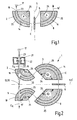
- Fig. 1 shows a schematic diagram of a simply constructed embodiment of a monochromator 1 according to the invention.
- the particle stream 23 of a beam source 17 strikes the input 16 of the monochromator 1 and is deflected by the deflection field 2 'of a first deflection element 2 to produce a dispersion 4 (see below).
- This deflection serves an inner electrode 24 and an outer electrode 25, which define an arcuate deflection path 14. If the particle stream 23 consists of electrons or negatively charged ions, then the inner electrode 24 is positive and the outer electrode 25 is negatively charged.
- the particle stream 23 along the optical axis E of the monochromator 1 deflected disperse on the lying in the plane 5 selection aperture 6 strikes, there is only the desired energy interval 7 passed.
- a further deflection element 8 is provided, whose deflection field 8 'brings the disperse rays back together and in this way provides a particle flow of higher monochromaticity at the outlet 16' of the monochromator 1.
- Fig. 2 shows a preferred embodiment of the invention.
- a monochromator 1 is shown, and a beam source 17, which is equipped for regulating and limiting the particle flow 23 with an electrostatic lens 21 and a diaphragm 22.
- the beam source 17 is a ZrO / W Schottky emitter with tungsten filament heating, suppressor and an anode formed as a circular aperture, the extractor.
- the potential of the extractor is usually the zero potential (axis potential) described here for the monochromator.
- This monochromator 1 has four deflection elements, wherein two deflection elements 2, 3 in front of the selection panel 6 and two further deflection elements 8, 9 after the selection panel 6 are arranged.
- this monochromator 1 is constructed such that the optical axis E describes the shape of a ⁇ .
- the arcuate paths describe arcs in the range between 120 ° and 150 °, since the deflection elements 2, 3, 8, 9 have corresponding angles ⁇ .
- the plane 5 of the selection aperture 6 is the plane of symmetry 5 'of the monochromator 1.
- the monochromator 1 is constructed such that the optical axis Es at the input 16 of the monochromator 1 runs exactly in the same direction as the one optical axis E A at the output 16 'of the monochromator 1.
- the deflector 2 and the deflector 8 are provided with beam passages 18, so that after switching off the monochromator 1, the beam bypassing the monochromator 1 directly from the input 16 to the output sixteenth 'is forwarded.
- the beam path is expediently designed such that the virtual input crossover 19 and the virtual output crossover 20 of the monochromator 1 coincide in its plane of symmetry 5 '.
- the same course of the beam path is achieved, regardless of whether the monochromator 1 is turned on or off.
- monochromator 1 is not monochromatized when Monochromator 1 is off.
- the image is completely preserved and at the same location, but with a lesser resolution due to the omission of the function of the monochromator 1.
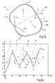
- Fig. 3 shows a charged particle beam 23 'at the input 16 of the monochromator 1.
- the particle stream 23 ' consists at the input 16 of the monochromator 1 of a plurality of charged particles, which do not exactly follow the optical axis Es at the input 16 of the monochromator 1, but have certain deviations thereof.
- This optical axis corresponds to the optical axis of the radiation source 17 as a rule.
- the charged particles emanating from this radiation source 17 have, apart from the theoretical possibility of a precise progression in the axis Es, certain angular deviations from the axis Es.
- angular deviations are detected by means of a spatial coordinate system x, y, z, where z corresponds to the course of the optical axis Es.
- the angular deviations are given as angle ⁇ or as angle ⁇ , which are the angles at which the charged particles virtually enter the image of the source (crossover 19 in FIG Fig. 2 ).
- the coordinates x and y are detected at the input 16 of the monochromator 1 and in the following representations the deflections A of the charge parts x ⁇ and y ⁇ to the optical axis E of the monochromator 1 shown.
- E ' is the respective location on the optical axis E, which corresponds to the abscissa in the diagrams 4b, 5b and 6b, on the ordinate, the deflection of the charged particles is plotted to the optical axis E.
- the path through the monochromator 1 would be exactly along its optical axis E.
- FIG. 12 shows an example of a course of a deflection path 14 of a monochromator 1 having a loop-shaped deflection path 14.
- Monochromators 1 have arcuate bends 14 to separate the charged particles of different energies. With such arcuate bends 14, faster, higher energy charged particles are carried outwardly and have an axis deviation d E - which is proportional to the energy deviation - from the axis E, as indicated by the dashed line E + d E for the strongest deviation. The reverse occurs with low energy charged particles following the dot-dash line E-dE.
- the axis deviation is proportional to the energy difference to the target energy.
- Fig. 4a only two deflecting elements 2 and 8 are used, wherein in the intermediate plane of symmetry 5 'of the monochromator 1, the selection aperture 6 is located.
- the plane 5 of the selection aperture 6 is here identical to the plane of symmetry 5 '.
- the illustration shows first the deflection elements 2 and 8 of the Fig. 4a corresponding deflection fields 2 'and 8'. Since these deflecting fields 2 'and 8' have asymmetrical fields 2 ', 8' with respect to the optical axis E in the x and y directions - only the strength of the dipole component ⁇ 1 can be seen here - the x ⁇ particles are deflected substantially differently like the y ⁇ particles.
- the x ⁇ particles are guided through the first deflection field 2 'by a zero crossing 11, so that there is a line focus or a line-shaped image of the radiation source 17 is formed.
- this point focus is a stroke by the dispersion 4 in the manner mentioned above, so that the selection of the desired energy interval 7 can be performed (see Fig. 7 ).
- This results in addition to an elimination 4 'of the dispersion 4, as well as the Fig. 4a it can be deduced that the curves E-dE, E and E + dE before the output 16 'of the monochromator 1 are reunited.
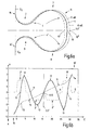
- Fig. 5a and 5b show another example, which corresponds to the just described, but the difference is that the loop of the deflection path 14 of four deflection elements 2, 3, 8, 9 of the Fig. 5a consists.
- a profile of the particles x ⁇ and y ⁇ is effected in contrast to the above by four deflection fields 2 ', 3', 8 'and 9', said deflection fields 2 ', 3', 8 ', 9' the four deflection elements. 2 , 3, 8, 9 correspond. Otherwise, the above applies in a corresponding manner.
- the Fig. 6a and 6b show the course of the deflection path 14, the deflection fields 2 ', 3', 8 ', 9' and the deflections A for a monochromator 1, the deflection path 14 has the shape of a ⁇ .
- the principles apply as described above, with the difference that the deflecting elements 2 and 3 have deflection fields 2 'and 3' acting in opposite directions, so that in this area of the track - as in FIG Fig. 6a to see - in between comes to a merger of the dispersion 4 different energies.
- Fig. 7 a a section through the selection panel 6 with these exemplary focus 10, 10 'and 10 ", of course, energies between 10' and 10" impinge on the selection panel 6 and only the desired energy interval 7 is transmitted.
- the two cones show (because of the above Course of the particle flow, all cones shown have elliptical cross-sections) with the tips in the point focus 10, for example, the merger of all particles of the exact energy corresponding to the axis E.
- the representation must be supplemented by the fact that a stroke extending from the point focus 10 'to the point focus 10 "is filled with such point focuses of different energies
- Fig. 7a illustrates, where it is shown that the aperture 6 only the desired energy interval 7 passes.
- the aperture of the aperture 6 can have almost any desired shape, it is only necessary to clearly delimit the line between 10 'and 10 "to the energy interval 7, even if the exact position of the particle stream may have certain deviations Aperture useful.
- the Fig. 8 shows a slit 29 of the prementioned prior art to illustrate the differences. Since there are no point focuses 10, 10 ', 10 ", but line focusses 31, 31', 31" are imagined as nothing but parallel lines between the line focus 31 'of least energy and the line focus 31 "of the strongest energy must, it is here required that the desired energy interval 7 is hidden by a slit 29. Therefore, the problem in the manner described above is that such a slit 29 must have exact side boundaries 29 ', 29 ".
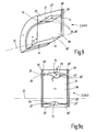
- Fig. 9 shows an embodiment of a deflection element 2, 3, 8 or 9 of the invention, wherein this consists of an inner electrode 24 and an outer electrode 25.
- the inner electrode 24 has frusto-conical surfaces 26, 26 'which are V-shaped and this "V" faces another "V” formed by the frusto-conical surfaces 27, 27' of the outer electrode 25.
- a rhomboid-shaped annular space (toroid - for calculation according to the SCOFF approximation) is formed which extends over the entire angular range of the arc angle ⁇ of the respective deflection element 2, 3, 8 or 9.
- the shielding plates which are arranged with a gap relative to the surfaces 36, 36 'of the deflecting elements 2, 3, 8, 9, which are aligned perpendicular to the axis E, ie to the deflection path 14.
- These shielding plates each have small holes in the region of the deflection path 14 as passage openings for the charged particle flow and are likewise at the extractor potential.
- These shielding plates can form box-shaped shields of the deflecting elements 2, 3, 8, 9 with the aforementioned plates.
- Fig. 9a shows a further embodiment of a deflecting 2, 3, 8 or 9, in which case the view perpendicular to the also in the Fig. 9 drawn surface 36 is directed.
- the surfaces 27, 27 'of the outer electrode 25 and the surfaces 26 and 26' of the inner electrode 24 are curved here.
- the x-, y- and z-axes of the curvilinear space coordinate system are shown, wherein the z-axis comes out perpendicular to the image plane and follows the course of the deflection path 14 here.
- the curved surfaces 26, 26 ', 27, 27' are symmetrical to the x-plane and always have the same distances and curvatures along the z-axis.
- the fact that the contour is deformed on the surface 36 'relative to the surface 36 comes only because the view of the surface 36 is perpendicular, the surface 36', however, extends obliquely backwards.
- Fig. 10a shows a schematic diagram of the cross section of a deflector 2, 3, 8, 9 with the formation of a hexapole.
- This cross section corresponds to the already in Fig. 9 cross section shown.
- the electrodes 24, 25 first form a dipole, which is sufficient to produce the desired deflection path 14. Only the required arcs have to be assembled with the corresponding bow angles ⁇ . However, such a composed of dipoles monochromator 1 would in turn generate image aberrations. These can be minimized by the use of multipole elements.
- Multipole elements in the sense used here are not pure multipole elements - if these are called those skilled in the art (see Kahl, supra) - but they are dipoles with an overlay by a multipole. Bending elements can be formed by their geometric shape to such superposed by multipoles dipoles.
- the Fig. 10a a schematic diagram of a possible geometric shape.
- a certain shaping of the equipotential lines 37, 37 ', 37 "occurs - According to the deflection path 14 - curved xz surface the zero potential 37 runs in the xy plane as a straight line through the electrodes 24, 25.
- Fig. 10b 2 shows another geometric shape of the surfaces 26, 26 ', 27, 27' of electrodes 24, 25. These have no symmetry with respect to the yz-section, whereby the equipotential line 37 of the extractor potential defined as zero potential is curved and also the other equipotential lines (FIG.
- the geometry shown by way of example can be used to form a dipole superimposed by a quadrupole, so that further variations of the different refractive powers in the xz and yz sections can be set Higher-order multipole elements possible if higher-order aberrations are to be corrected.
- the shapes of the deflection path 14 may also have other configurations, and it would of course also be possible to provide more than four deflection elements 2, 3, 8, 9.
- the shape of the electrodes 24 and 25 can be constructed in many different ways, instead of the surfaces 26, 26 ', 27, 27' could also find other various forms application. It is only important that they are far enough from the point symmetry of a spherical shape vary so that it does not come to point focuses within the deflection fields 2 ', 3', 8 ', 9'.
Applications Claiming Priority (1)
| Application Number | Priority Date | Filing Date | Title |
|---|---|---|---|
| DE102007024353A DE102007024353B4 (de) | 2007-05-24 | 2007-05-24 | Monochromator und Strahlquelle mit Monochromator |
Publications (3)
| Publication Number | Publication Date |
|---|---|
| EP1995758A2 true EP1995758A2 (fr) | 2008-11-26 |
| EP1995758A3 EP1995758A3 (fr) | 2010-06-30 |
| EP1995758B1 EP1995758B1 (fr) | 2012-06-20 |
Family
ID=39705187
Family Applications (1)
| Application Number | Title | Priority Date | Filing Date |
|---|---|---|---|
| EP08008712A Expired - Fee Related EP1995758B1 (fr) | 2007-05-24 | 2008-05-09 | Monochromateur et source de faisceau de particules chargées dotée d'un tel monochromateur |
Country Status (4)
| Country | Link |
|---|---|
| US (1) | US7745783B2 (fr) |
| EP (1) | EP1995758B1 (fr) |
| JP (1) | JP5441357B2 (fr) |
| DE (1) | DE102007024353B4 (fr) |
Families Citing this family (9)
| Publication number | Priority date | Publication date | Assignee | Title |
|---|---|---|---|---|
| US8013298B2 (en) * | 2008-07-14 | 2011-09-06 | National University Of Singapore | Electrostatic electron spectrometry apparatus |
| US8053725B2 (en) * | 2009-06-29 | 2011-11-08 | Fei Company | Beam quality in FIB systems |
| DE102010041813A1 (de) * | 2010-09-30 | 2012-04-05 | Carl Zeiss Nts Gmbh | Teilchenstrahlgerät und Verfahren zur Untersuchung und/oder Bearbeitung eines Objekts |
| EP2453461A1 (fr) | 2010-11-10 | 2012-05-16 | FEI Company | Source de particule chargée avec un filtre d'énergie électrostatique intégrée |
| KR101633978B1 (ko) | 2014-06-20 | 2016-06-28 | 한국표준과학연구원 | 모노크로메이터 및 이를 구비한 하전입자빔 장치 |
| DE102014019408B4 (de) * | 2014-12-22 | 2017-02-09 | MAX-PLANCK-Gesellschaft zur Förderung der Wissenschaften e.V. | Abbildende Energiefiltervorrichtung und Verfahren zu deren Betrieb |
| JP2018518005A (ja) * | 2016-05-20 | 2018-07-05 | 韓国標準科学研究院Korea Reserch Institute Of Standards And Science | モノクロメーターを備えた電子線装置 |
| KR101787379B1 (ko) * | 2016-05-25 | 2017-10-18 | 한국표준과학연구원 | 모노크로미터의 제조방법 |
| DE102022120496A1 (de) * | 2022-08-12 | 2024-02-15 | Carl Zeiss Multisem Gmbh | Teilchenoptische Anordnung, insbesondere Vielstrahl-Teilchenmikroskop, mit einer Magnetanordnung zum Separieren eines primären und eines sekundären teilchenoptischen Strahlenganges |
Citations (5)
| Publication number | Priority date | Publication date | Assignee | Title |
|---|---|---|---|---|
| EP0470299A1 (fr) | 1990-08-08 | 1992-02-12 | Koninklijke Philips Electronics N.V. | Filtre en énergie pour appareil à faisceau de particules chargées |
| DE10020382A1 (de) | 2000-04-26 | 2001-10-31 | Ceos Gmbh | Strahlerzeugungssystem für Elektronen oder Ionenstrahlen hoher Monochromasie oder hoher Stromdichte |
| DE10252129A1 (de) | 2002-11-04 | 2004-05-27 | Omicron Nano Technology Gmbh | Energiefilter für elektrisch geladene Teilchen und Verwendung des Energiefilters |
| DE102005031537A1 (de) | 2004-06-28 | 2006-01-19 | Grzelakowski, Krzysztof, Dr. | Abbildender Energiefilter für Elektronen und andere elektrisch geladene Teilchen und Methode der Energiefilterung der Elektronen und anderen elektrisch geladenen Teilchen mit dem abbildenden Energiefilter in elektrooptischen Geräten |
| DE19633496B4 (de) | 1996-08-20 | 2006-06-08 | Ceos Corrected Electron Optical Systems Gmbh | Monchromator für die Elektronenoptik, insbesondere Elketronenmikroskopie |
Family Cites Families (12)
| Publication number | Priority date | Publication date | Assignee | Title |
|---|---|---|---|---|
| US3863068A (en) * | 1972-07-27 | 1975-01-28 | Max Planck Gesellschaft | Time-of-flight mass spectrometer |
| JPS6269455A (ja) * | 1985-09-20 | 1987-03-30 | Nippon Telegr & Teleph Corp <Ntt> | 静電形集束偏向装置 |
| JP2856518B2 (ja) * | 1990-07-20 | 1999-02-10 | 日本電子株式会社 | E×b型エネルギーフィルタ |
| JPH0479139A (ja) * | 1990-07-20 | 1992-03-12 | Jeol Ltd | E×b型エネルギーフィルタ |
| JP3400284B2 (ja) * | 1997-02-27 | 2003-04-28 | 日本電子株式会社 | オメガ型エネルギーフィルタ及び該フィルタを組み込んだ電子顕微鏡 |
| JP3518271B2 (ja) * | 1997-08-28 | 2004-04-12 | 株式会社日立製作所 | エネルギーフィルタおよびこれを備えた電子顕微鏡 |
| JPH11233062A (ja) * | 1998-02-10 | 1999-08-27 | Jeol Ltd | ウィーンフィルタ及び直接写像型反射電子顕微鏡 |
| JP2001244186A (ja) * | 2000-03-01 | 2001-09-07 | Toshiba Corp | 電子ビーム描画装置及び方法 |
| JP2002025485A (ja) * | 2000-07-06 | 2002-01-25 | Jeol Ltd | エネルギーフィルタ |
| DE10061798A1 (de) * | 2000-12-12 | 2002-06-13 | Leo Elektronenmikroskopie Gmbh | Monochromator für geladene Teilchen |
| JP3696827B2 (ja) * | 2001-12-07 | 2005-09-21 | 日本電子株式会社 | エネルギーフィルタ |
| JP3867048B2 (ja) * | 2003-01-08 | 2007-01-10 | 株式会社日立ハイテクノロジーズ | モノクロメータ及びそれを用いた走査電子顕微鏡 |
-
2007
- 2007-05-24 DE DE102007024353A patent/DE102007024353B4/de not_active Expired - Fee Related
-
2008
- 2008-05-09 EP EP08008712A patent/EP1995758B1/fr not_active Expired - Fee Related
- 2008-05-20 US US12/153,455 patent/US7745783B2/en active Active
- 2008-05-23 JP JP2008135745A patent/JP5441357B2/ja active Active
Patent Citations (6)
| Publication number | Priority date | Publication date | Assignee | Title |
|---|---|---|---|---|
| EP0470299A1 (fr) | 1990-08-08 | 1992-02-12 | Koninklijke Philips Electronics N.V. | Filtre en énergie pour appareil à faisceau de particules chargées |
| EP0470299B1 (fr) | 1990-08-08 | 1996-06-26 | Koninklijke Philips Electronics N.V. | Filtre en énergie pour appareil à faisceau de particules chargées |
| DE19633496B4 (de) | 1996-08-20 | 2006-06-08 | Ceos Corrected Electron Optical Systems Gmbh | Monchromator für die Elektronenoptik, insbesondere Elketronenmikroskopie |
| DE10020382A1 (de) | 2000-04-26 | 2001-10-31 | Ceos Gmbh | Strahlerzeugungssystem für Elektronen oder Ionenstrahlen hoher Monochromasie oder hoher Stromdichte |
| DE10252129A1 (de) | 2002-11-04 | 2004-05-27 | Omicron Nano Technology Gmbh | Energiefilter für elektrisch geladene Teilchen und Verwendung des Energiefilters |
| DE102005031537A1 (de) | 2004-06-28 | 2006-01-19 | Grzelakowski, Krzysztof, Dr. | Abbildender Energiefilter für Elektronen und andere elektrisch geladene Teilchen und Methode der Energiefilterung der Elektronen und anderen elektrisch geladenen Teilchen mit dem abbildenden Energiefilter in elektrooptischen Geräten |
Also Published As
| Publication number | Publication date |
|---|---|
| US7745783B2 (en) | 2010-06-29 |
| US20080290273A1 (en) | 2008-11-27 |
| DE102007024353B4 (de) | 2009-04-16 |
| EP1995758A3 (fr) | 2010-06-30 |
| DE102007024353A1 (de) | 2008-11-27 |
| JP2008293977A (ja) | 2008-12-04 |
| JP5441357B2 (ja) | 2014-03-12 |
| EP1995758B1 (fr) | 2012-06-20 |
Similar Documents
| Publication | Publication Date | Title |
|---|---|---|
| EP1995758B1 (fr) | Monochromateur et source de faisceau de particules chargées dotée d'un tel monochromateur | |
| EP0617451B1 (fr) | Filtre en énergie d'électrons, produisant une image | |
| EP0218920B1 (fr) | Filtre d'énergie électronique de type Oméga | |
| EP0530640B1 (fr) | Système de formation d'images de faisceau de particules chargées avec miroir correcteur | |
| DE112013006811B4 (de) | Mehrfach reflektierendes Flugzeitmassenspektrometer | |
| DE60029041T2 (de) | Teilchenstrahlapparat mit Kompensation der chromatischen Aberration | |
| DE911878C (de) | Magnetische Elektronenlinse, insbesondere fuer Elektronenmikroskope | |
| DE112014003890B4 (de) | Mit einem Strahl geladener Teilchen arbeitende Vorrichtung | |
| DE102016009641B4 (de) | Detektor- und Schlitzkonfiguration in einem lsotopenverhältnis-Massenspektrometer | |
| DE3913965A1 (de) | Direkt abbildendes sekundaerionen-massenspektrometer mit laufzeit-massenspektrometrischer betriebsart | |
| DE102017000329B4 (de) | Quadrupol-Massenspektrometer | |
| EP1220292A2 (fr) | Monochromateur pour particules chargées | |
| DE1539660A1 (de) | Linsenkonstruktion fuer Einzelstrahlung und Mikroanalysevorrichtung,bestehend aus Mitteln zur Richtung eines Ionenstrahls auf einen gewaehlten Oberflaechenabschnitt einer Materialprobe | |
| EP3712924B1 (fr) | Dispositif et procédé de transfert d'électrons d'un échantillon à un analyseur d'énergie et dispositif spectromètre d'électrons | |
| DE2011491A1 (de) | Magnetischer Spektrograph | |
| DE1937482B2 (de) | Mikrostrahlsonde | |
| DE102020107738B3 (de) | Teilchenstrahl-System mit einer Multipol-Linsen-Sequenz zur unabhängigen Fokussierung einer Vielzahl von Einzel-Teilchenstrahlen, seine Verwendung und zugehöriges Verfahren | |
| DE102020123567A1 (de) | Vielzahl-Teilchenstrahl-System mit Kontrast-Korrektur-Linsen-System | |
| DE3123418C2 (de) | Doppelfokussierendes Massenspektrometer | |
| EP1559126B1 (fr) | Filtre d'energie generateur d'images pour particules chargees electriquement et utilisation de ce filtre | |
| EP1451847B1 (fr) | Correcteur en optique des particules | |
| DE2213208A1 (de) | Korpuskularstrahloptisches abbildungssystem | |
| DE10235981B9 (de) | Teilchenoptische Vorrichtung und Elektronenmikroskop | |
| EP1410416B1 (fr) | Systeme de lentilles a fentes pour faisceaux de particules | |
| EP1352410B1 (fr) | Correcteur electrostatique |
Legal Events
| Date | Code | Title | Description |
|---|---|---|---|
| PUAI | Public reference made under article 153(3) epc to a published international application that has entered the european phase |
Free format text: ORIGINAL CODE: 0009012 |
|
| AK | Designated contracting states |
Kind code of ref document: A2 Designated state(s): AT BE BG CH CY CZ DE DK EE ES FI FR GB GR HR HU IE IS IT LI LT LU LV MC MT NL NO PL PT RO SE SI SK TR |
|
| AX | Request for extension of the european patent |
Extension state: AL BA MK RS |
|
| PUAL | Search report despatched |
Free format text: ORIGINAL CODE: 0009013 |
|
| AK | Designated contracting states |
Kind code of ref document: A3 Designated state(s): AT BE BG CH CY CZ DE DK EE ES FI FR GB GR HR HU IE IS IT LI LT LU LV MC MT NL NO PL PT RO SE SI SK TR |
|
| AX | Request for extension of the european patent |
Extension state: AL BA MK RS |
|
| RIC1 | Information provided on ipc code assigned before grant |
Ipc: H01J 37/26 20060101ALI20100526BHEP Ipc: H01J 49/48 20060101ALI20100526BHEP Ipc: H01J 37/05 20060101AFI20080916BHEP Ipc: H01J 37/153 20060101ALI20100526BHEP |
|
| 17P | Request for examination filed |
Effective date: 20101207 |
|
| AKX | Designation fees paid |
Designated state(s): CZ DE GB NL |
|
| GRAP | Despatch of communication of intention to grant a patent |
Free format text: ORIGINAL CODE: EPIDOSNIGR1 |
|
| RIC1 | Information provided on ipc code assigned before grant |
Ipc: H01J 37/26 20060101ALI20111102BHEP Ipc: H01J 49/48 20060101ALI20111102BHEP Ipc: H01J 37/05 20060101AFI20111102BHEP Ipc: H01J 37/153 20060101ALI20111102BHEP |
|
| GRAS | Grant fee paid |
Free format text: ORIGINAL CODE: EPIDOSNIGR3 |
|
| RIN1 | Information on inventor provided before grant (corrected) |
Inventor name: UHLEMANN, STEPHAN, DR. |
|
| GRAA | (expected) grant |
Free format text: ORIGINAL CODE: 0009210 |
|
| AK | Designated contracting states |
Kind code of ref document: B1 Designated state(s): CZ DE GB NL |
|
| REG | Reference to a national code |
Ref country code: GB Ref legal event code: FG4D Free format text: NOT ENGLISH |
|
| REG | Reference to a national code |
Ref country code: DE Ref legal event code: R096 Ref document number: 502008007442 Country of ref document: DE Effective date: 20120816 |
|
| REG | Reference to a national code |
Ref country code: NL Ref legal event code: T3 |
|
| PLBE | No opposition filed within time limit |
Free format text: ORIGINAL CODE: 0009261 |
|
| STAA | Information on the status of an ep patent application or granted ep patent |
Free format text: STATUS: NO OPPOSITION FILED WITHIN TIME LIMIT |
|
| 26N | No opposition filed |
Effective date: 20130321 |
|
| REG | Reference to a national code |
Ref country code: DE Ref legal event code: R097 Ref document number: 502008007442 Country of ref document: DE Effective date: 20130321 |
|
| PGFP | Annual fee paid to national office [announced via postgrant information from national office to epo] |
Ref country code: CZ Payment date: 20220204 Year of fee payment: 15 |
|
| PGFP | Annual fee paid to national office [announced via postgrant information from national office to epo] |
Ref country code: NL Payment date: 20220519 Year of fee payment: 15 |
|
| PGFP | Annual fee paid to national office [announced via postgrant information from national office to epo] |
Ref country code: GB Payment date: 20220421 Year of fee payment: 15 Ref country code: DE Payment date: 20220127 Year of fee payment: 15 |
|
| REG | Reference to a national code |
Ref country code: DE Ref legal event code: R082 Ref document number: 502008007442 Country of ref document: DE Representative=s name: ALTMANN STOESSEL DICK PATENTANWAELTE PARTG MBB, DE |
|
| REG | Reference to a national code |
Ref country code: DE Ref legal event code: R119 Ref document number: 502008007442 Country of ref document: DE |
|
| REG | Reference to a national code |
Ref country code: NL Ref legal event code: MM Effective date: 20230601 |
|
| GBPC | Gb: european patent ceased through non-payment of renewal fee |
Effective date: 20230509 |
|
| PG25 | Lapsed in a contracting state [announced via postgrant information from national office to epo] |
Ref country code: CZ Free format text: LAPSE BECAUSE OF NON-PAYMENT OF DUE FEES Effective date: 20230509 |
|
| PG25 | Lapsed in a contracting state [announced via postgrant information from national office to epo] |
Ref country code: NL Free format text: LAPSE BECAUSE OF NON-PAYMENT OF DUE FEES Effective date: 20230601 |