EP1995508A2 - Flachbildschirm und Flachbildschirmgerät damit - Google Patents
Flachbildschirm und Flachbildschirmgerät damit Download PDFInfo
- Publication number
- EP1995508A2 EP1995508A2 EP08103137A EP08103137A EP1995508A2 EP 1995508 A2 EP1995508 A2 EP 1995508A2 EP 08103137 A EP08103137 A EP 08103137A EP 08103137 A EP08103137 A EP 08103137A EP 1995508 A2 EP1995508 A2 EP 1995508A2
- Authority
- EP
- European Patent Office
- Prior art keywords
- display
- flat
- combining
- main body
- receiving
- Prior art date
- Legal status (The legal status is an assumption and is not a legal conclusion. Google has not performed a legal analysis and makes no representation as to the accuracy of the status listed.)
- Granted
Links
Images


Classifications
-
- F—MECHANICAL ENGINEERING; LIGHTING; HEATING; WEAPONS; BLASTING
- F16—ENGINEERING ELEMENTS AND UNITS; GENERAL MEASURES FOR PRODUCING AND MAINTAINING EFFECTIVE FUNCTIONING OF MACHINES OR INSTALLATIONS; THERMAL INSULATION IN GENERAL
- F16M—FRAMES, CASINGS OR BEDS OF ENGINES, MACHINES OR APPARATUS, NOT SPECIFIC TO ENGINES, MACHINES OR APPARATUS PROVIDED FOR ELSEWHERE; STANDS; SUPPORTS
- F16M13/00—Other supports for positioning apparatus or articles; Means for steadying hand-held apparatus or articles
- F16M13/02—Other supports for positioning apparatus or articles; Means for steadying hand-held apparatus or articles for supporting on, or attaching to, an object, e.g. tree, gate, window-frame, cycle
-
- F—MECHANICAL ENGINEERING; LIGHTING; HEATING; WEAPONS; BLASTING
- F16—ENGINEERING ELEMENTS AND UNITS; GENERAL MEASURES FOR PRODUCING AND MAINTAINING EFFECTIVE FUNCTIONING OF MACHINES OR INSTALLATIONS; THERMAL INSULATION IN GENERAL
- F16M—FRAMES, CASINGS OR BEDS OF ENGINES, MACHINES OR APPARATUS, NOT SPECIFIC TO ENGINES, MACHINES OR APPARATUS PROVIDED FOR ELSEWHERE; STANDS; SUPPORTS
- F16M11/00—Stands or trestles as supports for apparatus or articles placed thereon ; Stands for scientific apparatus such as gravitational force meters
- F16M11/02—Heads
- F16M11/04—Means for attachment of apparatus; Means allowing adjustment of the apparatus relatively to the stand
- F16M11/06—Means for attachment of apparatus; Means allowing adjustment of the apparatus relatively to the stand allowing pivoting
- F16M11/08—Means for attachment of apparatus; Means allowing adjustment of the apparatus relatively to the stand allowing pivoting around a vertical axis, e.g. panoramic heads
-
- G—PHYSICS
- G06—COMPUTING OR CALCULATING; COUNTING
- G06F—ELECTRIC DIGITAL DATA PROCESSING
- G06F1/00—Details not covered by groups G06F3/00 - G06F13/00 and G06F21/00
- G06F1/16—Constructional details or arrangements
- G06F1/1601—Constructional details related to the housing of computer displays, e.g. of CRT monitors, of flat displays
-
- G—PHYSICS
- G06—COMPUTING OR CALCULATING; COUNTING
- G06F—ELECTRIC DIGITAL DATA PROCESSING
- G06F2200/00—Indexing scheme relating to G06F1/04 - G06F1/32
- G06F2200/16—Indexing scheme relating to G06F1/16 - G06F1/18
- G06F2200/161—Indexing scheme relating to constructional details of the monitor
Definitions
- the present general inventive concept relates to a flat display and a flat display apparatus having the same, and more particularly, to a flat display which has an improved display combining structure and a flat display apparatus having the same.
- a flat display is a term collectively mentioning a TV, a computer monitor and other known displays in the art.
- the flat display has a display main body, a display panel which forms an image, and/or a backlight unit which is provided at the back side of the display panel.
- the flat display has a small thickness from front to rear compared to a cathode ray tube (CRT) monitor, and has been used in many fields.
- CTR cathode ray tube
- the display panel forms the image using digital light processing (DLP), a liquid crystal display (LCD), a plasma display panel (PDP) or other known display panels in the art.
- DLP digital light processing
- LCD liquid crystal display
- PDP plasma display panel
- a flat display apparatus where one large screen is formed by disposing a number of displays to be adjacent therebetween.
- a flat display apparatus having a 4x4 array of the displays that is, 4 displays in a row and 4 displays in a column
- the present general inventive concept provides a flat display and a flat display apparatus having the same where a combination between flat displays can be made quickly and easily.
- the present general inventive concept also provides the flat display and flat display apparatus having the same where a combining structure of the flat displays can be easily changed.
- the present general inventive concept also provides the flat display and flat display apparatus having the same whose external appearance and reliability can be improved.
- a flat display including a display main body to receive a display panel to display an image and a receiving member which is formed with receiving holes disposed at opposite lateral sides of the display main body.
- the receiving holes may penetrate along the opposite lateral sides of the display main body.
- the receiving hole may have a shape of a circle or a rectangle.
- the receiving holes may be formed at upper and lower portions of the opposite lateral sides of the display main body respectively to have the same axis therethrough.
- the receiving holes may also face each other at the opposite lateral sides of the display main body and are spaced apart from a projection area of the display panel at a back side of the display panel.
- the receiving holes may face each other at the opposite lateral sides of the display main body and are spaced apart from a projection area of the display panel at a back side of the display panel.
- the flat display may further include a reinforcing member to correspond to a shape of the receiving member and to be combined to the receiving member.
- the flat display may further include a combining member to correspond to a shape of the receiving member or the reinforcing member and to be combined to the receiving member or the reinforcing member.
- the combining member may have an inserting portion which is combined to the receiving member or the reinforcing member, and a protruding member having a circumference larger than a circumference of the inserting portion.
- the flat display may further include an engaged portion which is formed in one of the reinforcing member and the combining member, and an engaging portion which is formed in an other of the reinforcing member and the combining member to be engaged with the engaged portion.
- a flat display apparatus including a stand, a display which has a display main body to receive a display panel to display an image, and a receiving member that is formed with receiving holes disposed at opposite lateral sides of the display main body, a combining member which is combined to the receiving member to form a display column by laying the display on the stand in a vertical direction and a rotating member which is combined with the combining member so that at least one display column can be rotated with respect to at least an other display column.
- the receiving holes may face each other at the opposite lateral sides of the display main body and are spaced apart from a projection area of the display panel at a back side of the display panel.
- the flat display apparatus may further include a reinforcing member to correspond to a shape of the receiving member and to be combined to the receiving member.
- the combining member may have an inserting portion which is combined to the receiving member or the reinforcing member, and a protruding member having a circumference larger than a circumference of the inserting portion.
- a displaying apparatus usable with a plurality of flat panels including a first combining member to couple a first set of adjacent flat displays to form a first display column, a second combining member to couple a second set of adjacent flat displays to form a second display column and a rotating member to rotatably couple the first combining member and the second combining member to allow the first display column to rotate with respect to the second display column.
- a method of displaying a plurality of flat panels including forming a first display column by coupling a first set of adjacent flat displays through a first combining member, forming a second display column by coupling a second set of adjacent flat displays through a second combining member to form a second display column and rotatably coupling the first combining member and the second combining member through a rotating member to allow the first display column to rotate with respect to the second display column.
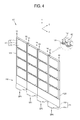
- a flat display 120 As illustrated in FIGS. 1 to 10 , a flat display 120 according to various embodiments of the present general inventive concept has a display main body 121 ( FIG. 2 ) and a receiving member 151. As illustrated in FIGS. 4 to 10 , a flat display apparatus 100 according to various embodiments of the present general inventive concept includes a stand 110, displays 120, combining members 157 and rotating members 160.
- the display columns are referred to as a first display column DP1, a second display column DP2, a third display column DP3 and a fourth display column DP4 in order from left to right thereof(refer to an axis direction "X" in FIG. 4 ). That is, in the first display column DP1, four flat displays 120 of reference numerals DP11, DP21, DP31 and DP41 are disposed in a vertical direction (refer to an axis direction "Y" in FIG. 4 ).
- four flat displays 120 of reference numerals DP12, DP22, DP32 and DP42 are disposed in the vertical direction in the second display column DP2
- four flat displays 120 of reference numerals DP13, DP23, DP33 and DP43 are disposed in the vertical direction in the third display column DP3
- four flat displays 120 of reference numerals DP14, DP24, DP34 and DP44 are disposed in the vertical direction in the fourth display column DP4, respectively.
- reference numerals Y1 to Y8 in FIG. 4 are lines, which vertically extend from a center axis of the combining member 157 in each display column DP, and are substantially parallel with the axis direction Y.
- i means a row number and "j” means a column number.
- the display column may be indicated as only “DP” if there is no need to divide the display column.
- the stand 110 supports the flat display 120 against an installation surface.
- the stand 110 includes a stand main body 111, a rolling member 117 and a securing member 119.
- the stand main body 111 includes a vertical member 113 which is combined with the flat display 120 in the vertical direction, and a horizontal member 115 which is combined with a lower end portion of the vertical member 113 in a transverse direction of the vertical member 113. Accordingly, the display column DP can be stably supported by the stand main body 111.
- the rolling member 117 is combined to a lower portion of the horizontal member 115 so that the stand main body 111 can be rotated with respect to the installation surface.
- the rolling member 117 includes a caster.
- Such a rolling member 117 may include a unit or portion to move to a predetermined position with respect to the installation surface and fixing its position with respect to the installation surface, for example, the caster with a brake mounted thereon.
- the securing member 119 is combined to a lower portion of the stand main body 111 so that the stand main body 111 can be prevented from moving with respect to the installation surface and a height of the stand main body 111 can be adjusted.
- four securing members 119 may be disposed at a lower end portion of the horizontal member 115 in the lower portion of the stand main body 111 to be separated therebetween as distantly as possible. Accordingly, the height of the flat displays 120 can be adjusted to be uniform by adjusting the height of the securing member 119 even if the installation surface is uneven or inclined. Therefore, each display column DP can be stably supported, and a stability and reliability of the flat display apparatus 100 can be improved.
- the display column DP is disposed vertically (that is, the axis Y direction in FiG. 4 ) by combining the flat display 120 with the stand 110. Each screen surface 125 of the flat displays 120 in the display column DP is disposed to form a same plane surface.
- the display column DP is formed by vertically combining the stand 110 and the flat displays 120 using the combining unit 150 ( FIG. 1 ), thus forming a large multi-screen.
- the display column DP is exemplarily embodied by combining four flat displays 120 and a stand 110.
- the display column DP may also be formed by vertically disposing two flat displays 120, five flat displays 120 or other number of the flat displays 120.
- four display columns DP are horizontally combined therebetween.
- three or five or other number of the display columns DP may be horizontally combined therebetween.
- the flat display 120 includes the display main body 121 which has a display opening 123, and a display panel 127 which includes a screen surface 125 which forms an image and is disposed in the display opening 123.
- the display main body 121 has the display opening 123 in its central area, where the display opening receives the screen surface 125 forming the image.
- the display main body 121 includes the receiving member 151 at opposite lateral areas thereof.
- the display main body 121 receives a display panel 127 ( FIG. 2 ), and may be formed by combining a front cover (not illustrated) and a rear cover (not illustrated).
- a combining unit 150 includes the receiving member 151, the combining member 157 and a rotating member 160.
- the combining unit 150 may include a reinforcing member 155.
- the receiving member 151 is formed at opposite lateral areas of the display main body 121 in the axis Y direction, and includes a receiving hole 151a.
- the receiving member 151 is sufficiently strong enough to receive and solidly support a combining member 157 which vertically combines the display main body 121.
- a reinforcing member 155 may be combined to the receiving member 151 in consideration of a size of the flat display 120, a number of the flat displays 120 that are disposed in the vertical direction and other factors.
- the receiving hole 151a is penetratingly formed to be apart from a projection area of the display panel 127 ( FIG. 2 ). Also, as illustrated in FIG. 3 , another exemplary embodiment of the receiving hole 151a is formed to be apart from the projection area of the display panel 127 not penetratingly but in upper and lower portions of the opposite lateral sides of the display main body 121 to have the same axis respectively. That is, center left side of the display main body 121 coincides with the axis Y1, and the center line of the upper and lower receiving holes 151a2 at the right side of the display main body 121 coincides with the axis Y2.
- the receiving hole 151a is distant apart from end portions of the opposite lateral sides of the display panel 127 in a predetermined distance (refer to "X" in FIG. 2 ) and is distant apart from an end portion of a back side of the display panel 127 in a predetermined distance (refer to "Y” in FIG. 2 ).
- the distances X and Y are determined in consideration of material of the display main body 121, the number of the flat displays 120 that are disposed in the vertical direction, the size of the flat display 120 and others.
- the reinforcing member 155 can be combined to the receiving member 151.
- the reinforcing member 155 reinforces a strength of the combining member 157 and may have a shape of a rectangle or a circle.
- the shape of the reinforcing member 155 is not limited to the rectangle and the circle but may also be any other shape.
- the reinforcing member 155 may be made of metal so that it can support the strength of the display main bodies 121 that are disposed in the vertical direction.
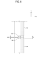
- the combining member 157 is provided between the display main bodies 121 and combined with the reinforcing member 155.
- the combining member 157 includes an inserting portion 157a and a protruding portion 157b.
- the inserting portion 157a extends upwards and downwards from the protruding portion 157b respectively to be combined with the reinforcing member 155.
- the inserting portion 157a is received within the reinforcing member 155 having the shape of a rectangular tube, and has a shape of a rectangular member to correspond to the shape of the reinforcing member 155.
- the inserting portion 157a and the receiving member 151 are provided to have a rectangular shape, so that they cannot be rotated with respect to the display main body 121.
- the inserting portion 157a or the receiving member 151 may also be provided to have a cylindrical shape, so that they can be rotated with respect to the display main body 121.
- the protruding portion 157b is provided at a central area of the combining member 157 and has a circular shape.
- a rotating hole 163 of the rotating member 160 is combined to the protruding portion 157b, thus enabling the rotating member 160 to be rotatable with respect to the protruding portion 157b. Accordingly, while rotating, the display column DP can be integrally rotated by the combining unit 150.
- an external appearance of the display main body 121 can be improved. Also, a comparably improved outer appearance can be maintained while the display main body 121 is combined.
- the rotating member 160 is combined to the combining member 157 so that at least one adjacent display column DP can be rotated with respect to at least one display column DP.
- the rotating member 160 may have a shape of a metal plate.
- the rotating member 160 includes a rotating main body 161 and a rotating hole 163.
- the rotating main body 161 is provided to have a shape of a plate and maintains enough strength while the display column DP is rotated.
- the rotating main body 161 may have a shape such that it can maintain a comparably favorable outer appearance while the flat display 120 is combined.
- the rotating hole 163 is penetratingly formed at both lateral portions of the rotating main body 161.
- the rotating hole 163 is combined with the combining member 157 so that it can be rotated with respect to the combining member 157 while the display column DP is rotated.
- the combining member 157 and the rotating member 160 may combine the flat displays 120 so that there is no gap between the flat displays 120 when the display column DP is seen from a front side.
- height (refer to "H” in FIG. 6 ) of the protruding portion 157b may be adjusted so that the gap between the upper and lower flat displays 120 or the gap between the flat display 120 and the stand 110 can be minimized (refer to "GAP1" in FIG. 6 ).
- pitch or distance of the rotating hole 163 of the rotating member 160 may be adjusted so that the gap (refer to "GAP2" in FIG. 7 ) between horizontally adjacent displays 120 can be minimized.
- the display column DP can be conveniently rotated with respect to an adjacent display column DP.
- the combining unit 150 can be easily assembled or installed.
- an engaged portion 170 is depressively formed in an inner portion of the reinforcing member 155 to be engaged with an engaging portion 180.
- the engaged portion 170 may be formed in the combining member 157.
- the engaging portion 180 elastically protrudes to an outer side of the combining member 157 to be engaged with the engaged portion 170.
- the engaging portion 180 may be formed in the reinforcing member 155.
- the engaging portion 180 is engages with the engaged portion 170, and the reinforcing member 155 and the combining member 157 maintain a stably combined state. Therefore, the rotating member 160 can be maintained to be stably rotated while it is rotated, so that reliability of the apparatus according to the present general inventive concept can be improved.
- the combining member 253 according to an exemplary embodiment of the present general inventive concept has a different shape from the previous exemplary embodiment illustrated in FIG. 5 .
- the combining member 253 according to the exemplary embodiment of FIGS. 8 and 9 may also perform functions of the reinforcing member 155 of the previous exemplary embodiment at the same time. That is, the combining member 253 includes an integrated receiving portion 253a which is received in the receiving member 251, and an integrated protruding portion 253b which extends from the integrated receiving portion 253a to be combined with a rotating member 260. In this case, a lower end portion of the integrated receiving portion 253a has a stopper 257.
- the combining unit 250 includes the receiving member 251, the combining member 253 and the rotating member 260.
- the combining unit 250 according to the exemplary embodiment of FIGS. 8 and 9 has a structure simpler than the combining unit 150 according to the exemplary embodiment as illustrated in FIG. 1 .
- the first display column DP can be rotated clockwise by 90 degrees around the axis Y3 with regard to the second display column DP2 and the third display column DP3, and the fourth display column DP4 can be rotated counterclockwise by 90 degrees around the axis Y6. Accordingly, a plan view of the display columns DP of the flat display apparatus 100 has a shape of " ".
- the third display column DP3 and the fourth display column DP4 can be rotated counterclockwise around the axis Y4 with regard to the second display column DP2. Accordingly, as illustrated in FIG. 11B , the plan view of the display columns DP of the flat display apparatus 100 has a shape of " ⁇ ".
- the shape in FIG. 11B may also be obtained by rotating the first display column DP1 and the second display column DP2 clockwise around the axis Y5 with regard to the third display column DP3.
- a rotating operation of the combining unit 150 is described as follows with reference to FIG. 11C .
- the third display column DP3 is supposed to be rotated with respect to the second display column DP2.
- the third display column DP3 can be rotated unitil the screen surface 125 of the second display column DP2 is perpendicular to that of the third display column DP3.
- the rotating main body 161 is rotated counterclockwise around the axis Y4 of the second display column DP2. That is, an outer surface of the protruding portion 157b contacts an inner surface of the rotating hole 163 and is rotated therebetween.
- the schematic plan view of the display columns DP of the flat display apparatus 100 may have various shapes including " ⁇ ", " “ and others. Also, it is easy to variously change the shape of the display column DP, thus enabling to easily respond to spaces with various shapes. Also, the combined structure of the display 120 or the display column DP may be easily and quickly changed.
- each display 120 is supposed to display an area of an entire image by dividing the entire image into 16 equal areas.
- Each display 120 displays one sixteenth of the entire image respectively by adjusting a size and a position of the entire image.
- Each display 120 displays a partial area of the entire image by adjusting a size variable which is provided to adjust the size of the image displayed on the screen and a position variable which is provided to adjust the position of the image displayed on the screen into a predetermined size variable and position variable.
- a video signal input into the display DP11 (hereinafter, called as "first display") that is located at an upper portion of the first display column DP1 is the upper left corner region of an image where the size of the entire image is increased horizontally and vertically by four times respectively to display the entire image "TEST".
- first display a video signal input into the display DP11 (hereinafter, called as "first display") that is located at an upper portion of the first display column DP1 is the upper left corner region of an image where the size of the entire image is increased horizontally and vertically by four times respectively to display the entire image "TEST".
- a partial area of the entire image is displayed on each of the remaining displays 120, and a combination of the images displayed on each display 120 may correspond to the entire image.
- each display column DP may also be easily changed by a controlling unit (not illustrated).
- Fig. 13 is a flowchart illustrating a method of displaying a plurality of flat panels according to another embodiment of the present general inventive concept.
- a first display column is formed by coupling a first set of adjacent flat displays through a first combining member.
- a second display column is formed by coupling a second set of adjacent flat displays through a second combining member to form a second display column.
- the first combining member and the second combining member is rotatably coupled through a rotating member to allow the first display column to rotate with respect to the second display column.
- the flat display apparatus 100 may include various control methods to display a large screen image.
- a combining of the displays can be accomplished quickly and easily.
- a combined structure of display columns can be easily changed.
- an outer appearance and reliability can be improved.
Landscapes
- Engineering & Computer Science (AREA)
- General Engineering & Computer Science (AREA)
- Mechanical Engineering (AREA)
- Theoretical Computer Science (AREA)
- Devices For Indicating Variable Information By Combining Individual Elements (AREA)
- Computer Hardware Design (AREA)
- Human Computer Interaction (AREA)
- Physics & Mathematics (AREA)
- General Physics & Mathematics (AREA)
Applications Claiming Priority (1)
| Application Number | Priority Date | Filing Date | Title |
|---|---|---|---|
| KR1020070049626A KR101062201B1 (ko) | 2007-05-22 | 2007-05-22 | 평판 디스플레이 및 이를 갖는 평판 디스플레이장치 |
Publications (3)
| Publication Number | Publication Date |
|---|---|
| EP1995508A2 true EP1995508A2 (de) | 2008-11-26 |
| EP1995508A3 EP1995508A3 (de) | 2011-07-06 |
| EP1995508B1 EP1995508B1 (de) | 2014-05-14 |
Family
ID=39523695
Family Applications (1)
| Application Number | Title | Priority Date | Filing Date |
|---|---|---|---|
| EP08103137.9A Ceased EP1995508B1 (de) | 2007-05-22 | 2008-03-28 | Flachbildschirmgerät |
Country Status (4)
| Country | Link |
|---|---|
| US (1) | US8042698B2 (de) |
| EP (1) | EP1995508B1 (de) |
| KR (1) | KR101062201B1 (de) |
| CN (1) | CN101311998B (de) |
Cited By (23)
| Publication number | Priority date | Publication date | Assignee | Title |
|---|---|---|---|---|
| WO2014110378A1 (en) * | 2013-01-11 | 2014-07-17 | Atomic Design, Inc. | Display system |
| WO2014179607A1 (en) * | 2013-05-01 | 2014-11-06 | Revolution Display, Inc. | Modular light emitting displays and arrays of same |
| USD723624S1 (en) | 2013-01-11 | 2015-03-03 | Atomic Design, Inc. | Rotating display connector |
| USD736858S1 (en) | 2013-01-11 | 2015-08-18 | Atomic Design, Inc. | Panel display plate |
| EP3029657A1 (de) * | 2014-12-01 | 2016-06-08 | Samsung Electronics Co., Ltd | Mehrsichtanzeigesystem |
| EP3057385A1 (de) * | 2013-01-09 | 2016-08-17 | Yanping Liu | Frei klappbarer flexibler led-schirm |
| US9506636B2 (en) | 2014-05-20 | 2016-11-29 | Atomic Design Inc. | Lighted display connector |
| USD797857S1 (en) | 2015-06-19 | 2017-09-19 | Atomic Design Inc. | Panel connector |
| US9788668B2 (en) | 2015-06-19 | 2017-10-17 | Atomic Design Inc. | Display system |
| USD800840S1 (en) | 2015-06-19 | 2017-10-24 | Atomic Design Inc. | Panel connector |
| USD800839S1 (en) | 2015-06-19 | 2017-10-24 | Atomic Design Inc. | Base panel connector |
| USD800838S1 (en) | 2015-06-19 | 2017-10-24 | Atomic Design Inc. | Base panel connector |
| EP3236457A1 (de) * | 2016-04-18 | 2017-10-25 | LG Electronics Inc. | Anzeigevorrichtung |
| EP3236454A1 (de) * | 2016-04-18 | 2017-10-25 | LG Electronics Inc. | Anzeigevorrichtung |
| EP3236453A1 (de) * | 2016-04-18 | 2017-10-25 | LG Electronics Inc. | Anzeigevorrichtung |
| USD801433S1 (en) | 2015-06-18 | 2017-10-31 | Atomic Design Inc. | Base panel connector |
| USD802054S1 (en) | 2015-06-18 | 2017-11-07 | Atomic Design Inc. | Support connector |
| USD815689S1 (en) | 2015-10-14 | 2018-04-17 | Atomic Design Inc. | Display panel assembly |
| US10226715B2 (en) | 2015-10-14 | 2019-03-12 | Atomic Design Inc. | Display panel system |
| US10327545B2 (en) | 2016-08-26 | 2019-06-25 | Atomic Design Inc. | Display support system |
| EP2709086B1 (de) * | 2012-09-14 | 2019-08-21 | LG Electronics, Inc. | Vorrichtung mit Mehrfachanzeige |
| US10431130B2 (en) | 2015-12-10 | 2019-10-01 | Atomic Design Inc. | Display system |
| US10473260B2 (en) | 2016-08-26 | 2019-11-12 | Atomic Design Inc. | Display support system |
Families Citing this family (17)
| Publication number | Priority date | Publication date | Assignee | Title |
|---|---|---|---|---|
| WO2010079588A1 (ja) * | 2009-01-06 | 2010-07-15 | Necディスプレイソリューションズ株式会社 | 多画面表示装置の固定構造及び固定方法 |
| US8286810B2 (en) * | 2010-02-10 | 2012-10-16 | Pro-Mart Industries, Inc | Laundry rack |
| TWM392602U (en) * | 2010-03-15 | 2010-11-21 | Aopen Inc | Display rack and electronic display apparatus |
| US8256443B2 (en) * | 2010-05-25 | 2012-09-04 | Dan Neal | Collapsible privacy shelter |
| US20120105734A1 (en) * | 2010-11-02 | 2012-05-03 | Zakiyaa Jada Johnson | Multi-Panel Display Device |
| JP5232886B2 (ja) * | 2011-03-10 | 2013-07-10 | シャープ株式会社 | スタンド装置 |
| US20140239139A1 (en) * | 2013-02-28 | 2014-08-28 | Tait Technologies Bvba | Video display system and method for assembling |
| CN103405076B (zh) * | 2013-08-08 | 2015-07-08 | 杭州高脚马科技有限公司 | 拼接组装的展示体 |
| CN107578714B (zh) * | 2017-10-17 | 2023-09-29 | 深圳市创显光电有限公司 | 一种智能led显示屏 |
| KR102464234B1 (ko) * | 2018-02-28 | 2022-11-07 | 삼성전자주식회사 | 디스플레이 장치 |
| DE102019120506B4 (de) * | 2018-08-03 | 2025-05-08 | Jürgen Peter Hlady | Modulare stellwand für den innenbereich, verfahren zur errichtung der modularen stellwand für den innenbereich und verwendung der modularen stellwand für den innenbereich |
| DE202018104489U1 (de) | 2018-08-03 | 2018-08-16 | Jürgen Peter Hlady | Modulare Stellwand und Verwendung der modularen Stellwand |
| TWM595944U (zh) * | 2019-01-22 | 2020-05-21 | 宏齊科技股份有限公司 | 移動式顯示裝置 |
| JP7226237B2 (ja) * | 2019-10-15 | 2023-02-21 | トヨタ自動車株式会社 | 映像表示装置 |
| CA3096633A1 (en) * | 2019-10-23 | 2021-04-23 | Cable Management Solutions, Inc. | Cable conveyance systems incorporating electronic visual displays |
| CN213716389U (zh) * | 2020-12-21 | 2021-07-16 | 深圳市光祥科技股份有限公司 | 一种led显示屏箱体 |
| US11814842B2 (en) * | 2021-07-16 | 2023-11-14 | Christian P. Corson | Building panels and method of building construction |
Citations (1)
| Publication number | Priority date | Publication date | Assignee | Title |
|---|---|---|---|---|
| JPH10198286A (ja) | 1996-12-29 | 1998-07-31 | Taimu World:Kk | 組立式多画面表示装置 |
Family Cites Families (47)
| Publication number | Priority date | Publication date | Assignee | Title |
|---|---|---|---|---|
| US2194238A (en) * | 1938-10-24 | 1940-03-19 | Weaver William Rutledge | Display device |
| US2923417A (en) * | 1957-09-23 | 1960-02-02 | Walter T Sonksen | Display rack |
| US3426913A (en) * | 1966-06-27 | 1969-02-11 | James S Abatiell Jr | Structural system and components |
| US3957159A (en) * | 1972-03-31 | 1976-05-18 | Ready Metal Manufacturing Co. | Rotary storage unit |
| US3924749A (en) * | 1974-07-22 | 1975-12-09 | Roy Bernard Weston | Display device |
| US3960273A (en) * | 1975-02-14 | 1976-06-01 | Roy Bernard Weston | Display device |
| US4030219A (en) * | 1976-06-01 | 1977-06-21 | Package Exhibit Programs, Inc. | Portable display apparatus |
| US4250676A (en) * | 1978-09-19 | 1981-02-17 | Knoll International Inc. | Panel interconnecting and upholstery-retaining connection for a tubular frame |
| NZ214578A (en) * | 1985-12-16 | 1989-05-29 | Tube Fab Ltd | Partition wall construction |
| US4723819A (en) * | 1986-06-12 | 1988-02-09 | Shoe Spa Inc. | Merchandizing device |
| US4998023A (en) * | 1989-06-22 | 1991-03-05 | Lakeside Manufacturing, Inc. | Portable utility cart |
| US5115855A (en) * | 1990-11-05 | 1992-05-26 | Skyline Displays, Inc. | Flat panel portable exhibit display and hinge |
| US5226548A (en) * | 1991-12-12 | 1993-07-13 | Gressco, Ltd. | I-frame support for a rotatable display tower |
| US5280840A (en) * | 1993-04-12 | 1994-01-25 | Terpening Harold R | Card display arrangement |
| US5537766A (en) * | 1994-02-17 | 1996-07-23 | Classic Exhibits Inc. | Trade show display panels and display panel systems and methods for interconnecting the display panel systems |
| US5494178A (en) * | 1994-07-25 | 1996-02-27 | Alu Inc. | Display and decorative fixture apparatus |
| US5544438A (en) * | 1995-04-03 | 1996-08-13 | Fazekas; James I. | Card and picture holder |
| US6202369B1 (en) * | 1996-08-21 | 2001-03-20 | Stanley E. Partee | Universal anchor system |
| US6010017A (en) * | 1997-07-02 | 2000-01-04 | Visual Marketing Incorporated | Modular dispenser and display system |
| US5975660A (en) * | 1998-06-02 | 1999-11-02 | Suncast Corporation | Cabinet |
| US6105292A (en) * | 1998-07-10 | 2000-08-22 | International Visual Corporation | Modular display sign |
| US6065407A (en) * | 1998-07-27 | 2000-05-23 | Alltrend Co., Ltd. | Locking sleeve assembly for a display shelf |
| ITMI990004A1 (it) * | 1999-01-04 | 2000-07-04 | Giancarlo Locatelli | Tappezzeria con sussidio didattico integrato |
| US6394292B1 (en) * | 1999-01-19 | 2002-05-28 | Pro-Mart Industries, Inc. | Laundry stand |
| HK1042981B (zh) * | 1999-01-29 | 2006-07-28 | 高超明智公司 | 小型盘支架和夹持器 |
| US6260296B1 (en) * | 1999-03-22 | 2001-07-17 | Edgar F. Carney, Jr. | Photograph display system |
| US6951068B1 (en) * | 2000-04-07 | 2005-10-04 | Pikture Klips Llc | Method and apparatus for displaying works of art |
| CN1172233C (zh) * | 2000-10-24 | 2004-10-20 | 惠普公司 | 用于便携式计算机的可变尺寸的多面板显示器 |
| US6340092B1 (en) * | 2000-12-28 | 2002-01-22 | Mcgrath, Jr. Donald L. | Space saver |
| US6594078B2 (en) * | 2001-03-27 | 2003-07-15 | Clarity Visual Systems, Inc. | Interlocking mounting package having separatable chassis for use in multiscreen projection displays |
| US6575314B2 (en) * | 2001-06-29 | 2003-06-10 | Bob Siemon Designs, Inc. | Apparatus and method for displaying goods |
| US6956541B2 (en) * | 2001-10-08 | 2005-10-18 | Imagearray, Ltd. | Integrated electronic display |
| US6729054B1 (en) * | 2001-12-19 | 2004-05-04 | Daktronics, Inc. | Articulated continuous electronic display |
| US20050219807A1 (en) * | 2002-01-29 | 2005-10-06 | Kim Si H | Portable multi-display device |
| JP3682467B2 (ja) * | 2002-02-26 | 2005-08-10 | 典一 佐藤 | マルチディスプレイ装置 |
| US6926375B2 (en) * | 2002-05-24 | 2005-08-09 | Toshiba Transport Engineering Inc. | Unit connecting mechanism and image display device |
| US7373746B1 (en) * | 2002-07-17 | 2008-05-20 | Technalink, Inc. | Sign assembly with mounting assembly |
| JP3665063B2 (ja) * | 2003-01-09 | 2005-06-29 | シャープ株式会社 | 薄型表示装置及び表示部の抜脱方法 |
| GB0308957D0 (en) * | 2003-04-17 | 2003-05-28 | Lillishall Plastics And Engine | Tolerance ring assembly |
| DE602005011567D1 (de) * | 2005-01-13 | 2009-01-22 | Metallurg Gallina S P A | Befestigungsvorrichtung für Betätigungsgriff eines Wasserhahnes |
| US20070000849A1 (en) * | 2005-01-25 | 2007-01-04 | Daktronics, Inc. | Modular display system |
| US7878476B2 (en) * | 2005-03-29 | 2011-02-01 | Xybix Systems, Inc. | Apparatus for mounting a plurality of monitors having adjustable distance to a viewer |
| US8102333B2 (en) | 2005-04-28 | 2012-01-24 | Sony Corporation | Display device securing mechanism and display system that rotates display devices around a rotational axis |
| JP4778732B2 (ja) * | 2005-06-03 | 2011-09-21 | Idec株式会社 | 光照射装置 |
| JP4806215B2 (ja) * | 2005-06-07 | 2011-11-02 | Nec液晶テクノロジー株式会社 | 表示装置 |
| CN2864782Y (zh) | 2005-12-31 | 2007-01-31 | 联想(北京)有限公司 | 具有双屏幕结构的笔记本电脑 |
| JP3128970U (ja) * | 2006-11-14 | 2007-02-01 | 船井電機株式会社 | 表示画面旋回装置 |
-
2007
- 2007-05-22 KR KR1020070049626A patent/KR101062201B1/ko not_active Expired - Fee Related
- 2007-11-02 US US11/934,227 patent/US8042698B2/en active Active
-
2008
- 2008-03-28 EP EP08103137.9A patent/EP1995508B1/de not_active Ceased
- 2008-04-18 CN CN200810093666.0A patent/CN101311998B/zh not_active Expired - Fee Related
Patent Citations (1)
| Publication number | Priority date | Publication date | Assignee | Title |
|---|---|---|---|---|
| JPH10198286A (ja) | 1996-12-29 | 1998-07-31 | Taimu World:Kk | 組立式多画面表示装置 |
Cited By (31)
| Publication number | Priority date | Publication date | Assignee | Title |
|---|---|---|---|---|
| EP2709086B1 (de) * | 2012-09-14 | 2019-08-21 | LG Electronics, Inc. | Vorrichtung mit Mehrfachanzeige |
| EP3057385A1 (de) * | 2013-01-09 | 2016-08-17 | Yanping Liu | Frei klappbarer flexibler led-schirm |
| US11085183B2 (en) | 2013-01-11 | 2021-08-10 | Atomic Design Inc. | Display system |
| USD723624S1 (en) | 2013-01-11 | 2015-03-03 | Atomic Design, Inc. | Rotating display connector |
| USD736858S1 (en) | 2013-01-11 | 2015-08-18 | Atomic Design, Inc. | Panel display plate |
| US9254051B2 (en) | 2013-01-11 | 2016-02-09 | Atomic Design, Inc. | Display system |
| WO2014110378A1 (en) * | 2013-01-11 | 2014-07-17 | Atomic Design, Inc. | Display system |
| US10458115B2 (en) | 2013-01-11 | 2019-10-29 | Atomic Design, Inc. | Display system |
| WO2014179607A1 (en) * | 2013-05-01 | 2014-11-06 | Revolution Display, Inc. | Modular light emitting displays and arrays of same |
| JP2016520867A (ja) * | 2013-05-01 | 2016-07-14 | レボリューション ディスプレイ,エルエルシー | モジュラ発光ディスプレイ及びそのアレイ |
| US9506636B2 (en) | 2014-05-20 | 2016-11-29 | Atomic Design Inc. | Lighted display connector |
| EP3029657A1 (de) * | 2014-12-01 | 2016-06-08 | Samsung Electronics Co., Ltd | Mehrsichtanzeigesystem |
| US9854701B2 (en) | 2014-12-01 | 2017-12-26 | Samsung Electronics Co., Ltd. | Multivision display system |
| USD801433S1 (en) | 2015-06-18 | 2017-10-31 | Atomic Design Inc. | Base panel connector |
| USD802054S1 (en) | 2015-06-18 | 2017-11-07 | Atomic Design Inc. | Support connector |
| USD800839S1 (en) | 2015-06-19 | 2017-10-24 | Atomic Design Inc. | Base panel connector |
| USD800838S1 (en) | 2015-06-19 | 2017-10-24 | Atomic Design Inc. | Base panel connector |
| USD800840S1 (en) | 2015-06-19 | 2017-10-24 | Atomic Design Inc. | Panel connector |
| US9788668B2 (en) | 2015-06-19 | 2017-10-17 | Atomic Design Inc. | Display system |
| USD797857S1 (en) | 2015-06-19 | 2017-09-19 | Atomic Design Inc. | Panel connector |
| US10226715B2 (en) | 2015-10-14 | 2019-03-12 | Atomic Design Inc. | Display panel system |
| USD815689S1 (en) | 2015-10-14 | 2018-04-17 | Atomic Design Inc. | Display panel assembly |
| US10431130B2 (en) | 2015-12-10 | 2019-10-01 | Atomic Design Inc. | Display system |
| US10327349B2 (en) | 2016-04-18 | 2019-06-18 | Lg Electronics Inc. | Display device |
| US10390446B2 (en) | 2016-04-18 | 2019-08-20 | Lg Electronics Inc. | Display device |
| US10390445B2 (en) | 2016-04-18 | 2019-08-20 | Lg Electronics Inc. | Display device |
| EP3236453A1 (de) * | 2016-04-18 | 2017-10-25 | LG Electronics Inc. | Anzeigevorrichtung |
| EP3236454A1 (de) * | 2016-04-18 | 2017-10-25 | LG Electronics Inc. | Anzeigevorrichtung |
| EP3236457A1 (de) * | 2016-04-18 | 2017-10-25 | LG Electronics Inc. | Anzeigevorrichtung |
| US10327545B2 (en) | 2016-08-26 | 2019-06-25 | Atomic Design Inc. | Display support system |
| US10473260B2 (en) | 2016-08-26 | 2019-11-12 | Atomic Design Inc. | Display support system |
Also Published As
| Publication number | Publication date |
|---|---|
| KR20080102763A (ko) | 2008-11-26 |
| EP1995508A3 (de) | 2011-07-06 |
| US20080291611A1 (en) | 2008-11-27 |
| KR101062201B1 (ko) | 2011-09-05 |
| CN101311998B (zh) | 2014-02-26 |
| US8042698B2 (en) | 2011-10-25 |
| EP1995508B1 (de) | 2014-05-14 |
| CN101311998A (zh) | 2008-11-26 |
Similar Documents
| Publication | Publication Date | Title |
|---|---|---|
| EP1995508B1 (de) | Flachbildschirmgerät | |
| US7738245B1 (en) | Display mount | |
| TWI524771B (zh) | 顯示器支撐模組 | |
| US8508432B2 (en) | Multi-display apparatus | |
| KR101911795B1 (ko) | 접합 후 화소가 풀 커버된 전체적 제로-멀리온 비디오 월 시스템 | |
| US6918562B2 (en) | Device for combining electronic appliances and displaying apparatuses employing the same | |
| US20110163052A1 (en) | Supporting device of display apparatus | |
| US8390996B2 (en) | Display device | |
| JP4499771B2 (ja) | 二重画面ディスプレイパネル | |
| US20100158299A1 (en) | Position and directionality adjustable multi-range surround-sound speaker cabinet | |
| CN103389582A (zh) | 一种显示装置及其显示方法 | |
| US20080165991A1 (en) | Display device with sound module | |
| JP2001312219A (ja) | フラットディスプレイ用架台装置 | |
| US20050031144A1 (en) | Flat display apparatus | |
| US8066234B2 (en) | Image display apparatus | |
| KR100920154B1 (ko) | 영상장치용 레일식 브라켓 | |
| US20210195304A1 (en) | Display mount interfaces | |
| US12085223B1 (en) | Adjustable display panel rail connector | |
| WO2009107432A1 (ja) | 照明装置、表示装置、及びテレビ受信装置 | |
| JP2016219885A (ja) | ビューファインダ支持機構及びこれを備えたカメラ拡張装置 | |
| US20070091554A1 (en) | Display device | |
| EP1694064A1 (de) | Flachbildschirm Befestigungssystem | |
| KR20070116466A (ko) | 디스플레이유닛의 마운팅장치 | |
| KR20140123806A (ko) | 디스플레이장치용 지지장치 | |
| CA2711326C (en) | Multi-position mount for electronic display |
Legal Events
| Date | Code | Title | Description |
|---|---|---|---|
| PUAI | Public reference made under article 153(3) epc to a published international application that has entered the european phase |
Free format text: ORIGINAL CODE: 0009012 |
|
| AK | Designated contracting states |
Kind code of ref document: A2 Designated state(s): AT BE BG CH CY CZ DE DK EE ES FI FR GB GR HR HU IE IS IT LI LT LU LV MC MT NL NO PL PT RO SE SI SK TR |
|
| AX | Request for extension of the european patent |
Extension state: AL BA MK RS |
|
| PUAL | Search report despatched |
Free format text: ORIGINAL CODE: 0009013 |
|
| AK | Designated contracting states |
Kind code of ref document: A3 Designated state(s): AT BE BG CH CY CZ DE DK EE ES FI FR GB GR HR HU IE IS IT LI LT LU LV MC MT NL NO PL PT RO SE SI SK TR |
|
| AX | Request for extension of the european patent |
Extension state: AL BA MK RS |
|
| 17P | Request for examination filed |
Effective date: 20120105 |
|
| AKX | Designation fees paid |
Designated state(s): DE GB NL |
|
| 17Q | First examination report despatched |
Effective date: 20120614 |
|
| RAP1 | Party data changed (applicant data changed or rights of an application transferred) |
Owner name: SAMSUNG ELECTRONICS CO., LTD. |
|
| REG | Reference to a national code |
Ref country code: DE Ref legal event code: R079 Ref document number: 602008032225 Country of ref document: DE Free format text: PREVIOUS MAIN CLASS: F16M0013020000 Ipc: F16M0011080000 |
|
| RIC1 | Information provided on ipc code assigned before grant |
Ipc: F16M 13/02 20060101ALI20131029BHEP Ipc: F16M 11/08 20060101AFI20131029BHEP |
|
| GRAP | Despatch of communication of intention to grant a patent |
Free format text: ORIGINAL CODE: EPIDOSNIGR1 |
|
| INTG | Intention to grant announced |
Effective date: 20131210 |
|
| GRAS | Grant fee paid |
Free format text: ORIGINAL CODE: EPIDOSNIGR3 |
|
| GRAA | (expected) grant |
Free format text: ORIGINAL CODE: 0009210 |
|
| AK | Designated contracting states |
Kind code of ref document: B1 Designated state(s): DE GB NL |
|
| REG | Reference to a national code |
Ref country code: GB Ref legal event code: FG4D |
|
| REG | Reference to a national code |
Ref country code: DE Ref legal event code: R096 Ref document number: 602008032225 Country of ref document: DE Effective date: 20140626 |
|
| REG | Reference to a national code |
Ref country code: NL Ref legal event code: T3 |
|
| REG | Reference to a national code |
Ref country code: DE Ref legal event code: R097 Ref document number: 602008032225 Country of ref document: DE |
|
| PLBE | No opposition filed within time limit |
Free format text: ORIGINAL CODE: 0009261 |
|
| STAA | Information on the status of an ep patent application or granted ep patent |
Free format text: STATUS: NO OPPOSITION FILED WITHIN TIME LIMIT |
|
| 26N | No opposition filed |
Effective date: 20150217 |
|
| REG | Reference to a national code |
Ref country code: DE Ref legal event code: R097 Ref document number: 602008032225 Country of ref document: DE Effective date: 20150217 |
|
| PGFP | Annual fee paid to national office [announced via postgrant information from national office to epo] |
Ref country code: DE Payment date: 20200220 Year of fee payment: 13 Ref country code: GB Payment date: 20200225 Year of fee payment: 13 Ref country code: NL Payment date: 20200221 Year of fee payment: 13 |
|
| REG | Reference to a national code |
Ref country code: DE Ref legal event code: R119 Ref document number: 602008032225 Country of ref document: DE |
|
| REG | Reference to a national code |
Ref country code: NL Ref legal event code: MM Effective date: 20210401 |
|
| GBPC | Gb: european patent ceased through non-payment of renewal fee |
Effective date: 20210328 |
|
| PG25 | Lapsed in a contracting state [announced via postgrant information from national office to epo] |
Ref country code: DE Free format text: LAPSE BECAUSE OF NON-PAYMENT OF DUE FEES Effective date: 20211001 Ref country code: GB Free format text: LAPSE BECAUSE OF NON-PAYMENT OF DUE FEES Effective date: 20210328 Ref country code: NL Free format text: LAPSE BECAUSE OF NON-PAYMENT OF DUE FEES Effective date: 20210401 |