EP1994987A2 - Mikrofluidische Vorrichtung mit einem mikrofluidischen Chip sowie mikrofluidische Vorrichtung mit einem biomolekularen Mikroarray-Chip - Google Patents
Mikrofluidische Vorrichtung mit einem mikrofluidischen Chip sowie mikrofluidische Vorrichtung mit einem biomolekularen Mikroarray-Chip Download PDFInfo
- Publication number
- EP1994987A2 EP1994987A2 EP08156341A EP08156341A EP1994987A2 EP 1994987 A2 EP1994987 A2 EP 1994987A2 EP 08156341 A EP08156341 A EP 08156341A EP 08156341 A EP08156341 A EP 08156341A EP 1994987 A2 EP1994987 A2 EP 1994987A2
- Authority
- EP
- European Patent Office
- Prior art keywords
- microfluidic
- chip
- biomolecule
- platform
- chamber
- Prior art date
- Legal status (The legal status is an assumption and is not a legal conclusion. Google has not performed a legal analysis and makes no representation as to the accuracy of the status listed.)
- Withdrawn
Links
Images


Classifications
-
- G—PHYSICS
- G01—MEASURING; TESTING
- G01N—INVESTIGATING OR ANALYSING MATERIALS BY DETERMINING THEIR CHEMICAL OR PHYSICAL PROPERTIES
- G01N35/00—Automatic analysis not limited to methods or materials provided for in any single one of groups G01N1/00 - G01N33/00; Handling materials therefor
- G01N35/10—Devices for transferring samples or any liquids to, in, or from, the analysis apparatus, e.g. suction devices, injection devices
-
- B—PERFORMING OPERATIONS; TRANSPORTING
- B01—PHYSICAL OR CHEMICAL PROCESSES OR APPARATUS IN GENERAL
- B01L—CHEMICAL OR PHYSICAL LABORATORY APPARATUS FOR GENERAL USE
- B01L3/00—Containers or dishes for laboratory use, e.g. laboratory glassware; Droppers
- B01L3/50—Containers for the purpose of retaining a material to be analysed, e.g. test tubes
- B01L3/502—Containers for the purpose of retaining a material to be analysed, e.g. test tubes with fluid transport, e.g. in multi-compartment structures
- B01L3/5027—Containers for the purpose of retaining a material to be analysed, e.g. test tubes with fluid transport, e.g. in multi-compartment structures by integrated microfluidic structures, i.e. dimensions of channels and chambers are such that surface tension forces are important, e.g. lab-on-a-chip
- B01L3/502738—Containers for the purpose of retaining a material to be analysed, e.g. test tubes with fluid transport, e.g. in multi-compartment structures by integrated microfluidic structures, i.e. dimensions of channels and chambers are such that surface tension forces are important, e.g. lab-on-a-chip characterised by integrated valves
-
- G—PHYSICS
- G01—MEASURING; TESTING
- G01N—INVESTIGATING OR ANALYSING MATERIALS BY DETERMINING THEIR CHEMICAL OR PHYSICAL PROPERTIES
- G01N35/00—Automatic analysis not limited to methods or materials provided for in any single one of groups G01N1/00 - G01N33/00; Handling materials therefor
-
- B—PERFORMING OPERATIONS; TRANSPORTING
- B01—PHYSICAL OR CHEMICAL PROCESSES OR APPARATUS IN GENERAL
- B01L—CHEMICAL OR PHYSICAL LABORATORY APPARATUS FOR GENERAL USE
- B01L2200/00—Solutions for specific problems relating to chemical or physical laboratory apparatus
- B01L2200/02—Adapting objects or devices to another
- B01L2200/025—Align devices or objects to ensure defined positions relative to each other
-
- B—PERFORMING OPERATIONS; TRANSPORTING
- B01—PHYSICAL OR CHEMICAL PROCESSES OR APPARATUS IN GENERAL
- B01L—CHEMICAL OR PHYSICAL LABORATORY APPARATUS FOR GENERAL USE
- B01L2200/00—Solutions for specific problems relating to chemical or physical laboratory apparatus
- B01L2200/06—Fluid handling related problems
- B01L2200/0621—Control of the sequence of chambers filled or emptied
-
- B—PERFORMING OPERATIONS; TRANSPORTING
- B01—PHYSICAL OR CHEMICAL PROCESSES OR APPARATUS IN GENERAL
- B01L—CHEMICAL OR PHYSICAL LABORATORY APPARATUS FOR GENERAL USE
- B01L2200/00—Solutions for specific problems relating to chemical or physical laboratory apparatus
- B01L2200/16—Reagents, handling or storing thereof
-
- B—PERFORMING OPERATIONS; TRANSPORTING
- B01—PHYSICAL OR CHEMICAL PROCESSES OR APPARATUS IN GENERAL
- B01L—CHEMICAL OR PHYSICAL LABORATORY APPARATUS FOR GENERAL USE
- B01L2300/00—Additional constructional details
- B01L2300/04—Closures and closing means
-
- B—PERFORMING OPERATIONS; TRANSPORTING
- B01—PHYSICAL OR CHEMICAL PROCESSES OR APPARATUS IN GENERAL
- B01L—CHEMICAL OR PHYSICAL LABORATORY APPARATUS FOR GENERAL USE
- B01L2300/00—Additional constructional details
- B01L2300/06—Auxiliary integrated devices, integrated components
- B01L2300/0627—Sensor or part of a sensor is integrated
- B01L2300/0636—Integrated biosensor, microarrays
-
- B—PERFORMING OPERATIONS; TRANSPORTING
- B01—PHYSICAL OR CHEMICAL PROCESSES OR APPARATUS IN GENERAL
- B01L—CHEMICAL OR PHYSICAL LABORATORY APPARATUS FOR GENERAL USE
- B01L2300/00—Additional constructional details
- B01L2300/08—Geometry, shape and general structure
- B01L2300/0803—Disc shape
- B01L2300/0806—Standardised forms, e.g. compact disc [CD] format
-
- B—PERFORMING OPERATIONS; TRANSPORTING
- B01—PHYSICAL OR CHEMICAL PROCESSES OR APPARATUS IN GENERAL
- B01L—CHEMICAL OR PHYSICAL LABORATORY APPARATUS FOR GENERAL USE
- B01L2400/00—Moving or stopping fluids
- B01L2400/04—Moving fluids with specific forces or mechanical means
- B01L2400/0403—Moving fluids with specific forces or mechanical means specific forces
- B01L2400/0409—Moving fluids with specific forces or mechanical means specific forces centrifugal forces
-
- B—PERFORMING OPERATIONS; TRANSPORTING
- B01—PHYSICAL OR CHEMICAL PROCESSES OR APPARATUS IN GENERAL
- B01L—CHEMICAL OR PHYSICAL LABORATORY APPARATUS FOR GENERAL USE
- B01L2400/00—Moving or stopping fluids
- B01L2400/06—Valves, specific forms thereof
- B01L2400/0677—Valves, specific forms thereof phase change valves; Meltable, freezing, dissolvable plugs; Destructible barriers
-
- B—PERFORMING OPERATIONS; TRANSPORTING
- B01—PHYSICAL OR CHEMICAL PROCESSES OR APPARATUS IN GENERAL
- B01L—CHEMICAL OR PHYSICAL LABORATORY APPARATUS FOR GENERAL USE
- B01L3/00—Containers or dishes for laboratory use, e.g. laboratory glassware; Droppers
- B01L3/50—Containers for the purpose of retaining a material to be analysed, e.g. test tubes
- B01L3/502—Containers for the purpose of retaining a material to be analysed, e.g. test tubes with fluid transport, e.g. in multi-compartment structures
- B01L3/5027—Containers for the purpose of retaining a material to be analysed, e.g. test tubes with fluid transport, e.g. in multi-compartment structures by integrated microfluidic structures, i.e. dimensions of channels and chambers are such that surface tension forces are important, e.g. lab-on-a-chip
- B01L3/502707—Containers for the purpose of retaining a material to be analysed, e.g. test tubes with fluid transport, e.g. in multi-compartment structures by integrated microfluidic structures, i.e. dimensions of channels and chambers are such that surface tension forces are important, e.g. lab-on-a-chip characterised by the manufacture of the container or its components
-
- B—PERFORMING OPERATIONS; TRANSPORTING
- B01—PHYSICAL OR CHEMICAL PROCESSES OR APPARATUS IN GENERAL
- B01L—CHEMICAL OR PHYSICAL LABORATORY APPARATUS FOR GENERAL USE
- B01L7/00—Heating or cooling apparatus; Heat insulating devices
- B01L7/52—Heating or cooling apparatus; Heat insulating devices with provision for submitting samples to a predetermined sequence of different temperatures, e.g. for treating nucleic acid samples
-
- B—PERFORMING OPERATIONS; TRANSPORTING
- B01—PHYSICAL OR CHEMICAL PROCESSES OR APPARATUS IN GENERAL
- B01L—CHEMICAL OR PHYSICAL LABORATORY APPARATUS FOR GENERAL USE
- B01L9/00—Supporting devices; Holding devices
- B01L9/52—Supports specially adapted for flat sample carriers, e.g. for plates, slides, chips
- B01L9/527—Supports specially adapted for flat sample carriers, e.g. for plates, slides, chips for microfluidic devices, e.g. used for lab-on-a-chip
-
- Y—GENERAL TAGGING OF NEW TECHNOLOGICAL DEVELOPMENTS; GENERAL TAGGING OF CROSS-SECTIONAL TECHNOLOGIES SPANNING OVER SEVERAL SECTIONS OF THE IPC; TECHNICAL SUBJECTS COVERED BY FORMER USPC CROSS-REFERENCE ART COLLECTIONS [XRACs] AND DIGESTS
- Y10—TECHNICAL SUBJECTS COVERED BY FORMER USPC
- Y10T—TECHNICAL SUBJECTS COVERED BY FORMER US CLASSIFICATION
- Y10T436/00—Chemistry: analytical and immunological testing
- Y10T436/15—Inorganic acid or base [e.g., hcl, sulfuric acid, etc. ]
Definitions
- Apparatuses consistent with the present invention relate to a microfluidic device, and more particularly, to a microfluidic device in which a process using a microfluidic chip can be automatically performed in a microfluidic structure formed in a platform, specifically, wherein an immune serum examination can be automatically performed using a biomolecule microarray chip.
- a microfluidic structure of a microfluidic device includes a chamber storing a small amount of a fluid, a channel through which the fluid flows, a valve which can control flow of the fluid, and various functional units performing predetermined functions using the fluid.
- a lab-on-a chip is structured such that the microfluidic structure is formed in a chip-shaped substrate to perform a biochemical reaction examination including many treating and manipulating processes.
- the microfluidic structure may require an operating pressure to transport a fluid.
- the operating pressure can be a capillary pressure or a pressure produced using a separate pump.
- disk-type microfluidic devices including disk-type microfluidic structures in which a fluid is transported using a centrifugal force for processes to be performed have been developed. Such a technique is called a lab compact disk (CD) or a lab-on a disk.
- CD lab compact disk
- a lab-on a disk the application range of the disk-type microfluidic devices is limited.
- a biomolecule microarray chip technique a plurality of biomolecule capture probes which can be specifically combined to different target materials are integrally bound to a chip-shaped substrate to detect a target material from a sample.
- the biomolecule capture probes may include a deoxyribonucleic acid (DNA) having a known base sequence, an antibody specifically binding to a target antigen, and the like.
- DNA deoxyribonucleic acid
- the biomolecule microarray chip is used in diagnosis or experiments, manual operations such as spotting or washing of a sample, are required to be performed by skilled technicians.
- a method of forming a microarray on a compact disk to detect a target material is disclosed in US Patent Publication No. US 2002/0177144 titled "Detection and/or qauntification of a target molecule by a binding with a capture molecule fixed on the surface of a disk.”
- US Patent Publication No. US 2002/0177144 titled "Detection and/or qauntification of a target molecule by a binding with a capture molecule fixed on the surface of a disk.”
- the present invention provides a microfluidic device using a microfluidic chip.
- the microfluidic device operations using various microfluidic chips formed in a platform can be automatically performed.
- various kinds of biomolecule microarray chips can be used, and at the same time, the number of manual processes required for experiments or diagnosis using a microarray chip can be reduced significantly.
- the present invention also provides an immune serum examination device in which an immune serum examination can be automatically performed using a protein microarray chip.
- a microfluidic device using a biomolecule microarray chip including: a platform which is rotatable; a microfluidic structure disposed in the platform, including: a plurality of chambers; a plurality of channels connecting the chambers each other; and a plurality of valves controlling flow of a fluid through the channels, wherein the microfluidic structure controls flow of a fluid sample using rotation of the platform and the valves, and a biomolecule microarray chip mounted in the platform such that biomolecule capture probes bound to the surface of the biomolecule microarray chip contact the fluid sample in the microfluidic structure.
- the microfluidic structure includes a reagent chamber storing a reagent which selectively binds a target biomolecule in the fluid sample and emits an optical indication, and a blend of the reagent and the fluid sample contacts the biomolecule microarray chip.
- the microfluidic structure includes a buffer solution chamber storing a buffer solution, and the microarray chip is washed with different parts of the buffer solution in a plurality of washing processes.
- the microfluidic structure includes a centrifugation unit separating a sample having particles into a fluid and particles using a centrifugal force generated due to rotation of the platform, wherein the fluid separated contacts the microarray chip.
- the microfluidic structure includes a reaction chamber and the biomolecule microarray chip forms one of inner walls of the reaction chamber.
- the microfluidic structure includes: a reagent chamber storing a reagent which selectively binds a target biomolecule in the fluid sample and emits an optical indication; a buffer solution chamber storing a buffer solution; and a centrifugation unit separating a sample having particles into a fluid and particles using a centrifugal force generated due to rotation of the platform, wherein the centrifugation unit, the reaction chamber, and the buffer solution chamber are connected to the reaction chamber.
- the microarray chip can be mounted in a platform using various methods.
- the platform includes a top plate and a bottom plate, wherein the microfluidic structure is formed in facing surfaces of the top plate and bottom plate, an opening corresponding to the reaction chamber is formed in the bottom plate, and the opening is covered by the biomolecule microarray chip so that the reaction chamber is formed between a front surface of the biomolecule microarray chip and the top plate.
- the platform includes a top plate and a bottom plate, wherein the microfluidic structure is formed in facing surfaces of the top plate and bottom plate, an opening corresponding to the reaction chamber is formed in the top plate, the biomolecule microarray chip is attached to the bottom plate exposed by the opening, and the opening is covered by a cover so that the reaction chamber is formed between a front surface of the biomolecule microarray chip and the cover.
- the platform includes a top plate and a bottom plate, wherein the microfluidic structure is formed in facing surfaces of the top plate and bottom plate, the biomolecule microarray chip is attached to an inner surface of the top plate or the bottom plate, and the reaction chamber is formed between the biomolecule microarray chip and another plate to which the microarray chip is not attached.
- Each biomolecule capture probe is selected from a nucleic acid, a protein, a cell, or a biochemical material, which specifically binds to a target material in a biomolecule sample.
- a microfluidic device using a biomolecule microarray chip including: a platform which is rotatable; a microfluidic structure disposed in the platform, including: a plurality of chambers; a plurality of channels connecting the chambers each other; and a plurality of valves controlling flow of a fluid through the channels, wherein the microfluidic structure controls flow of a fluid sample using rotation of the platform and the valves, and a biomolecule microarray chip mounted in the platform such that biomolecule capture probes bound to the surface of the biomolecule microarray chip contact the fluid sample in the microfluidic structure, wherein the microfluidic structure includes: a centrifugation unit separating a sample having particles into a fluid and particles using a centrifugal force generated due to rotation of the platform; a reagent chamber storing a reagent which selectively binds a target biomolecule in the fluid sample and emits an optical indication; a buffer solution chamber storing a buffer solution
- the valves includes a valve material having heat generating particles dispersed in a phase transition material dispersion medium, and includes a phase transition valve which is melted by heat generated due to an electromagnetic wave irradiated from an external energy source and thus opens or closes the channels.
- Each heat dissipating particle has a core that absorbs an electromagnetic wave from the outside to be converted into a thermal energy, and a shell surrounding the core.
- the microarray chip can be mounted in the platform using various methods.
- the platform includes a top plate and a bottom plate, wherein the microfluidic structure is formed in facing surfaces of the top plate and bottom plate, an opening corresponding to the reaction chamber is formed in the bottom plate, and the opening is covered by the biomolecule microarray chip so that the reaction chamber is formed between a front surface of the biomolecule microarray chip and the top plate.
- the platform includes a top plate and a bottom plate, wherein the microfluidic structure is formed in facing surfaces of the top plate and bottom plate, an opening corresponding to the reaction chamber is formed in the top plate, the biomolecule microarray chip is attached to the bottom plate exposed by the opening, and the opening is covered by a cover so that the reaction chamber is formed between a front surface of the biomolecule microarray chip and the cover.
- the platform includes a top plate and a bottom plate, wherein the microfluidic structure is formed in facing surfaces of the top plate and bottom plate, the biomolecule microarray chip is attached to an inner surface of the top plate or the bottom plate, and the reaction chamber is formed between the biomolecule microarray chip and another plate to which the microarray chip is not attached.
- a immune serum examination device using a protein microarray chip including: a platform that is rotatable; a microfluidic structure disposed in the platform, including: a plurality of chambers; a plurality of channels connecting the chambers each other; and a plurality of valves controlling flow of a fluid through the channels, wherein the microfluidic structure controls flow of a fluid sample using rotation of the platform and the valves, and a protein microarray chip mounted in the platform such that protein capture probes bound to the surface of the protein microarray chip contact the fluid sample in the microfluidic structure.
- a microfluidic device using a protein microarray chip including: a platform which is rotatable; a microfluidic structure disposed in the platform, including: a plurality of chambers; a plurality of channels connecting the chambers each other; and a plurality of valves controlling flow of a fluid through the channels, wherein the microfluidic structure controls flow of a fluid sample using rotation of the platform and the valves, and a protein microarray chip mounted in the platform such that protein capture probes bound to the surface of the protein microarray chip contact the fluid sample in the microfluidic structure, wherein the microfluidic structure includes: a centrifugation unit separating a sample having particles into a fluid and particles using a centrifugal force generated due to rotation of the platform; a reagent chamber storing a reagent which selectively binds a target protein in the fluid sample and emits an optical indication; a buffer solution chamber storing a buffer solution; a reaction chamber
- a microfluidic device including: a platform which is rotatable; a microfluidic structure disposed in the platform, including: a plurality of chambers; a plurality of channels connecting the chambers each other; and a plurality of valves controlling flow of a fluid through the channels, wherein the microfluidic structure controls flow of a fluid sample using rotation of the platform and the valves, and a microfluidic chip-receiving unit which is disposed in a portion of the microfluidic structure and includes an inlet through which a fluid is supplied to a biomolecule microfluidic chip comprised in the microfluidic chip-receiving unit and an outlet through which a fluid that has contacted the microfluidic chip is discharged.
- the inlet of the microfluidic chip-receiving unit is disposed closer to a rotation axis of the platform than the outlet.
- the microfluidic chip-receiving unit can be provided using various methods. If the microfluidic chip is a microarray chip requiring a space to contact a fluid in front of the microarry chip, the microfluidic chip-receiving unit may have the following structures.
- the platform includes a top plate and a bottom plate, wherein the microfluidic structure is formed in facing surfaces of the top plate and bottom plate, an opening exposing the microfluidic chip-receiving unit is formed in the bottom plate, and the opening is covered by the microfluidic chip so as to form a chamber between a front surface of the microfluidic chip and the top plate.
- the platform includes a top plate and a bottom plate, wherein the microfluidic structure is formed in facing surfaces of the top plate and bottom plate, an opening exposing the microfluidic chip-receiving unit is formed in the top plate, the microfluidic chip is attached to the bottom plate exposed by the opening, and the opening is covered by a cover so as to form a chamber between a front surface of the microfluidic chip and the cover.
- the platform includes a top plate and a bottom plate, wherein the microfluidic structure is formed in facing surfaces of the top plate and bottom plate, the microfluidic chip-receiving unit is formed in a chamber-like form between the top plate and the bottom plate, the microfluidic chip is attached to one of inner walls of the chamber, the microfluidic chip and the other inner walls of the chamber form a space.
- the microfluidic chip can be selected from a group comprising a microarray chip, a polymerase chain reaction (PCR) chip, a hexane nucleic acid refinement chip, and a sample separation chip.
- PCR polymerase chain reaction
- FIG. 1 is a plan view of a disk-type microfluidic device according to an exemplary embodiment of the present invention
- FIG. 2 is a plan view of a disk-type microfluidic device according to another exemplary embodiment of the present invention.
- FIG. 3 is a plan view of a disk-type microfluidic device according to another exemplary embodiment of the present invention.
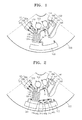
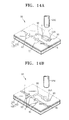
- FIG. 4 is a bottom perspective view illustrating a process of mounting a biomolecule microarray chip in a disk-type microfluidic device according to an exemplary embodiment of the present invention
- FIG. 5 is a front perspective view illustrating a process of mounting a biomolecule microarray chip in a disk-type microfluidic device according to another exemplary embodiment of the present invention
- FIG. 6 is a front perspective view illustrating a process of mounting a biomolecule microarray chip in a disk-type microfluidic device according to another exemplary embodiment of the present invention
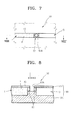
- FIG. 7 is a plan view of an opening valve used in the microfluidic devices of FIGS. 1 through 3 , according to an exemplary embodiment of the present invention.
- FIG. 8 is a sectional view of the opening valve taken along line VIII-VIII' of FIG. 7 , according to an exemplary embodiment of the present invention.
- FIG. 9 is a plan view of a closing valve of the microfluidic device of FIG. 2 , according to an exemplary embodiment of the present invention.
- FIG. 10 is a sectional view of the closing valve taken a long line X-X' of FIG. 9 , according to an exemplary embodiment of the present invention.
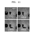
- FIG. 11 illustrates high-speed photos showing operation of the closing valve of FIG. 9 , according to an exemplary embodiment of the present invention
- FIG. 12 is a graph of volume fraction of a ferrofluid contained in a valve plug in the opening valve of FIG. 7 with respect to a valve response time, according to an exemplary embodiment of the present invention
- FIG. 13 is a graph of power of a laser light source that is an external energy source to operate the opening valve of FIG. 7 with respect to a valve response time, according to an exemplary embodiment of the present invention.
- FIG. 14A through FIG. 14f are perspective views sequentially illustrating an operation process of an open and close type valve of the microfluidic device of FIG. 3 , according to an exemplary embodiment of the present invention.
- micro- used in a micro chip or a microfluidic device is used to only have the opposite meaning to the term “macro-,” and is not limited to a unit of micro.
- FIG. 1 is a plan view of a disk-type microfluidic device according to an exemplary embodiment of the present invention.
- a microfluidic structure including a plurality of chambers 111, 120, 130, 140, and 150, channels (shown but not denoted with designated numbers) connecting the chambers to each other, and a plurality of valves 31, 32, and 33, and 34 controlling the flow of fluids through the channels is formed in a disk-type platform 100.
- multiple microfluidic structures may be formed in the disk-type platform 100.
- a biomolecule microarray chip 190 may be further mounted in the disk-type platform 100.
- the biomolecule microarray chip 190 includes a plurality of biomolecule capture probes 191n bound to its surface, and the biomolecule capture probes 191n are configured to contact a sample (not shown) which passes a portion of the microfluidic structure.
- the shape of the disk-type platform 100 is not limited to a disk shape that can rotate itself
- the disk-type platform 100 can have a fan shape that can rotate on a rotatable frame.
- the disk-type platform 100 can be formed of a plastic material that can be easily changed into a desired form and has a biologically inactive surface.
- the plastic material can be an acrylic such as polymethylmethacrylate (PMMA), polydimethylsiloxane (PDMS), polycarbonate (PC), etc.
- a material used to form the disk-type platform 100 is not limited thereto. That is, the disk-type platform 100 can be formed of other materials that are chemically and biologically stable and optically transparent, and that can be mechanically processed.
- the disk-type platform 100 can be a multi-layered panel.
- the disk-type platform 100 can have an inner space or an inner passage if the disk-type platform 100 is formed by combining panels having recessed structures corresponding to a chamber or a channel.
- the panels may be combined together using various methods. For example, panels can be combined together using a double-sided adhesive tape, or panels can be fused together by using ultrasonic waves.
- the microfluidic structure formed in the disk-type platform 100 may include a sample chamber 111 storing a sample, such as blood, sputum, or urine, a centrifugation unit 180 which is connected to the sample chamber 111 and separates the sample into a fluid, a cell, etc, a reagent chamber 130 storing a reagent, and a buffer solution chamber 120 storing a buffer solution.
- a sample chamber 111 storing a sample, such as blood, sputum, or urine
- a centrifugation unit 180 which is connected to the sample chamber 111 and separates the sample into a fluid, a cell, etc
- a reagent chamber 130 storing a reagent
- a buffer solution chamber 120 storing a buffer solution.
- the reagent chamber 130 stores a reagent containing a material that is selectively bound to a target biomolecule in a sample and emits an optical indication, such as fluorescence, adsorption, or emission.
- the buffer solution chamber 120 stores a buffer solution to be used to dilute the sample or wash the surface of the microarray chip 190 contacting the sample.
- the centrifugation unit 180, the reagent chamber 130, and the buffer solution chamber 120 are connected to a reaction chamber 140 through opening valves 31, 32, and 33 disposed at respective outlets in which the reaction chamber 140 is formed further from a rotation axis of the disk-type platform 100 than the respective outlets.
- the opening valves 31, 32, and 33 can be phase-transition type valves (refer to FIGS. 7 and 8 ) which are closed by valve plugs (not shown) formed of a valve material that is a solid-phase transition material containing heat generating particles dispersed therein and which are actively opened when operation energy is supplied by an external energy source.
- the reaction chamber 140 may include the microarray chip 190 forming a wall of the reaction chamber 140 and provides a space located before the microarray chip 190, in which various biomolecule capture probes 191 n may contact a fluid sample.
- the microarray chip 190 can be mounted in the disk-type platform 100 using various methods, which will be described in detail with reference to FIGS. 4 through 6 .
- a waste chamber 150 is disposed further from the rotation axis of the disk-type platform 100 than the reaction chamber 140.
- the waste chamber 150 stores a fluid discharged from the reaction chamber 140 through an outlet of the reaction chamber 140.
- An opening valve (normally closing valve) 34 is disposed at the outlet of the reaction chamber 140 and allows the fluid to stay only in the reaction chamber 140 when the reaction occurs.
- the centrifugation unit 180 includes a supernatant separation member 182 extending from an outlet of the sample chamber 111 in a direction opposite to the rotation axis, and includes a particle separation member 181 connected to the supernatant separation member 182 through a channel.
- One side of the supernatant separation member 182 is connected to the reaction chamber 140 through the opening valve 31 and a channel.
- the particle separation member 181 and the supernatant separation member 182 can be connected to each other through a detour channel 183.
- the detour channel 183 may act as a vent of the particle separation member 181.
- the detour channel 183 is connected to an excess sample chamber 184 at one side so that even when an excess amount of a sample is loaded to the sample chamber 111, a supernatant can be provided to the reaction chamber 140 in a constant amount.
- the buffer solution chamber 120 may be connected to the reaction chamber 140 through a plurality of channels.
- the channels are connected to different locations of the buffer solution chamber 120 according to levels of the buffer solution stored therein.
- the channels may include valves 32a, 32b, and 32c.
- the valves 32a, 32b, and 32c can be opening valves that can independently operate.
- the valves 32a, 32b, and 32c may control the amount of a buffer solution contained in the buffer solution chamber 120 so that a predetermined amount of the buffer solution is supplied to the reaction chamber 140 so as to wash the surface of the biomolecule microarray chip 190 several times when reactions are completed.
- the biomolecule microarray chip 190 can be any kind of a chip that includes various capture probes 191n capable of capturing a target biomolecule bound to a chip-shaped substrate in an array.
- the chip-shaped substrate can be glass, silicon, or plastic material
- the capture probe capable of capturing a target biomolecule can be proteins, nucleic acids, cells, or other biochemical molecules.
- a method of detecting a target biomolecule using the disk-type microfluidic device according to the present exemplary embodiment will now be described in detail. Specifically, an immune serum examination is performed using a protein microarray chip including protein capture probes bound to the surface of the protein microarray chip that is the biomolecule microarray chip 190 and blood that is a sample.
- the disk-type microfluidic device according to an exemplary embodiment of the present invention and a disk-type immune serum examination device can be more fully understood on the basis of following description.
- the protein microarray chip is denoted with the designation number of 190 since the protein microarray chip is an example of the biomolecule microarray chip 190.
- a particle separation member 181 collects heavy hemocytes, and a supernatant separation member 182 is mainly filled with a serum.
- an opening valve 31 of a channel connected to a reaction chamber 140 is opened, the serum located in a portion of the supernatant separation member 182 closer to a rotation axis than a portion of the supernatant separation member 182 connected to the channel is transferred to the reaction chamber 140. Therefore, elements that can inhibit precise detection can be removed in advance.
- the reagent can be a material that can be used to provide optical indication, such as a detection probe material used in an enzyme-linked immunoserological assay (ELISA).
- ELISA enzyme-linked immunoserological assay
- the reagent may include a secondary antibody which when bound to horseradish peroxidase (HRP) results in optical indication.
- HRP horseradish peroxidase
- the reagent may include a substrate or enzyme that emits a specific color when it reacts with the HRP.
- capture probes 191n corresponding to a target protein in a sample may capture the target protein, and a secondary antibody, that is, a material which can be used to provide optical indication, included in the reagent is bound to the target protein before or after the target protein is captured by the capture probes 191n.
- an opening valve 34 located at an outlet of the reaction chamber 140 is opened and then, the fluid in the reaction chamber 150 is discharged to a waste chamber 150 using a centrifugal force. Then, opening valves 32a, 32b, and 32c corresponding to various levels of the buffer solution chamber 120 are sequentially opened. Whenever the opening valves 32a, 32b, and 32c are opened, a predetermined amount of a buffer solution is transferred to the reaction chamber 140 using a centrifugal force to wash the surface of the protein microarray chip 190. The buffer solution that has been used to wash the surface of the microarray chip 190 is discharged to the waste chamber 150.
- FIG. 2 is a plan view of a disk-type microfluidic device according to another exemplary embodiment of the present invention.
- the current exemplary embodiment described with reference to FIG. 2 is the same as in the previous exemplary embodiment described with reference to FIG. 1 , except that the reaction chamber 140 is connected to the waste chamber 150 through four channels. Three out of the four channels include opening valves 34a, 34b, and 34c and closing valves 44a, 44b, and 44c respectively paired, and the other channel includes an opening valve 34d.
- the reaction chamber 140 can contain and discharge the fluid four times. Specifically, initially, the reaction chamber 140 can contain and discharge the blend of the sample and the reagent once. Then, the reaction chamber 140 can contain and discharge the buffer solution three times. The number of channels may be varied as required.
- FIG. 3 is a plan view of a disk-type microfluidic device according to another exemplary embodiment of the present invention.
- the current exemplary embodiment described with reference to FIG. 3 is the same as in the previous exemplary embodiment described with reference to FIG. 1 , except that an open and close type valve 50 that can be opened and closed several times is disposed in a channel connecting the reaction chamber 140 to the waste chamber 150.
- the reaction chamber 140 can contain and discharge a fluid several times using the open and close type valve 50. That is, initially, the blend of the sample and the reagent is contained and discharged in the reaction chamber 140, and then, the buffer solution is contained and discharged several times.
- the open and close type valve 50 can be opened and closed several times. The structure and operational principal of the open and close type valve 50 will be described with reference to FIGS. 15A through 15F.
- a disk-type platform 100 includes a top plate 101 and a bottom plate 102, a microfluidic structure is mounted in a recessed portion between the top plate 101 and the bottom plate 102, and the top plate 101 is combined with the bottom plate 102, excluding the microfluidic structure.
- the microfluidic structure excluding the reaction chamber 140 can be formed in a concave pattern in the bottom plate 102.
- the location of the microfluidic structure is not limited thereto.
- FIG. 4 is a bottom perspective view illustrating a process of mounting a biomolecule microarray chip 190a in a disk-type microfluidic device according to an exemplary embodiment of the present invention.
- FIG. 4 is a bottom view of a disk-type microfluidic device according to an exemplary embodiment of the present invention.
- a bottom plate 102 has an opening 102a corresponding to a reaction chamber.
- a groove 140a which is to form the reaction chamber with the biomolecule microarray chip 190a is formed in the opening 102a.
- the groove 140a may pass through the bottom plate 102 and extend to a portion of the top plate 101.
- the biomolecule microarray chip 190a covers the opening 140a such that a surface of the biomolecule microarray chip 190a to which various biomolecule capture probes are bound faces the groove 140a, thereby sealing the disk-type platform 100.
- the biomolecule microarray chip 190a can be fixed to the bottom plate 102 using various methods. For example, the fixing can be achieved using screws, pieces of double-sided tape, or adhesive materials.
- an open surface of the groove 140a is covered by the biomolecule microarray chip 190a to form a fluid-containable space, that is, the reaction chamber.
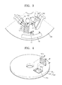
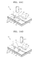
- FIG. 5 is a front perspective view illustrating a process of mounting a biomolecule microarray chip 190b in a disk-type microfluidic device according to another exemplary embodiment of the present invention.
- FIG. 5 is a top view of a disk-type microfluidic device according to an exemplary embodiment of the present invention (refer to FIGS. 1 through 3 .)
- a top plate 101 of the disk-type platform 100 includes an opening 101 a corresponding to a reaction chamber.
- a portion of a bottom plate 102 exposed by the opening 101a includes a groove 140b.
- the biomolecule microarray chip 190b is disposed at the bottom of the groove 140b, and the opening 101a is covered and sealed by a cover 101c.
- the depth of the groove 140b is greater than the thickness of the biomolecule microarray chip 190b so that a fluid-containable space can be formed between the biomolecule microarray chip 190b and the cover 101c, that is, such that the reaction chamber can be formed.
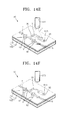
- FIG. 6 is a front perspective view illustrating a process of mounting a biomolecule microarray chip 190b in a disk-type microfluidic device according to another exemplary embodiment of the present invention.
- FIG. 6 is a view of a disk-type platform 100a including a top plate 101 1 and a bottom plate 102 before the top plate 101 and the bottom plate 102 are combined each other.
- the bottom plate 102 has a groove 140c corresponding to a reaction chamber.
- the biomolecule microarray chip 190b is disposed at the bottom of the groove 140c.
- the depth of the groove 140c may be greater than the thickness of the biomolecule microarray chip 190b so that a fluid-containable space, that is, the reaction chamber can be formed between the top plate 101 and the biomolecule microarray chip 190b.
- the chip mounting methods described with reference to FIGS. 4 through 6 may be suitable for mounting of a microarray chip that is a microfluidic chip.
- the microfluidic structures illustrated in FIGS. 1 through 3 may be suitable for an immune serum examination or a gene test using a microarray chip.
- the disk-type microfluidic device according to the exemplary embodiments of the present invention is not limited thereto.
- a disk-type microfluidic device according to another aspect of the present invention may include a microfluidic chip-receiving unit including various microfluidic chips, disposed in a portion of a microfluidic structure of a disk-type platform.
- the microfluidic chip-receiving unit may include an inlet through which a fluid is supplied to a microfluidic chip contained therein and an outlet through which the fluid that has contacted the microfluidic chip is discharged.
- Other kinds of microfluidic chips, in addition to the microarray chip, can also be mounted in a portion of a microfluidic structure of a disk-type platform using the methods described with reference to FIGS. 4 through 6 .
- the microfluidic chip can be selected from the group consisting of a microarray chip, a polymerase chain reaction (PCR) chip, a hexane nucleic acid refinement chip, and a sample separation chip.
- the microarray chip can be a protein microarray chip used for the immune serum examination as described above, a nucleic acid microarray chip, or a cell microarray chip.
- the PCR chip amplifies a gene through thermal cycling.
- the nucleic acid refinement chip refines a nucleic acid using a filter structure included in the chip.
- the sample separation chip separates a specific material from a sample containing various materials on the basis of a material transmission principle of diffusion or electrophoresis.
- FIG. 7 is a plan view of an opening valve 30 used as at least one of the opening valves included in the microfluidic devices of FIGS. 1 through 3 .
- FIG. 8 is a sectional view of the opening valve 30 taken along the line VIII-VIII' of FIG. 7 .
- the opening valve 30 may include a valve material that exists in a solid phase at room temperature.
- the valve material can be a dispersion medium composed of a phase transition material that exists in a solid phase at room temperature in which heat dissipating materials are dispersed.
- the valve plug 83 completely plugs an opening 83A of a channel 43 at room temperature to block a fluid F flowing from an inlet I to an outlet O.
- the valve plug 83 is melted at high temperature and moves to the channel 43, and then returns to a solid phase and the channel 43 for the fluid F is opened.
- the opening 83A may act as a valve material inlet through which the valve material melted is loaded to form a valve plug in a process of fabricating a microfluidic device.
- the valve plug 83 may be heated by an external energy source 300 (see FIGS. 14A through 14F ) outside the disk-type platform 100.
- the external energy source 300 may irradiate an electromagnetic wave to the valve plug 83 formed in an initial location, that is, to the opening 83A and an adjacent area to the opening 83A.
- the external energy source 300 can be, for example, a laser light source irradiating a laser beam.
- the laser light source irradiating a laser beam may include at least one laser diode.
- each laser pulse may have the energy of 1 mJ/pulse or more.
- the pulse laser may have the output energy of 10 mW or more.
- the laser light source is not limited thereto. That is, the external energy source 300 can be any laser light source irradiating a wavelength from 400 to 1300 nm.
- the channel 43 can be provided using a relief pattern formed in an inner surface of the top plate 101 or bottom plate 102 of the disk-type platform 100.
- the top plate 101 may be formed of an optically transparent material so that an electromagnetic wave irradiated from the external energy source 300 can be incident on the valve plug 83, and the flow of the fluid F can be observed outside.
- a suitable material for the top plate 101 can be glass or a transparent plastic substance in terms of optical transparency and manufacturing costs.
- the heat generating particles dispersed in the valve plug 83 may have a width of a few thousands of micrometers ( ⁇ m) and a diameter from 1 nm to 100 ⁇ m so that the heat generating particles can flow easily in the channel 43.
- ⁇ m micrometers
- the heat generating particles may be uniformly dispersed in wax.
- the heat generating particles may be structured such that each dissipating particle includes a core including a metal and a shell having a hydrophobic property.
- each dissipating particle may include a core formed of Fe that is a ferromagnetic material and a shell formed of surfactants binding and surrounding the Fe.
- heat generating particles are stored being dispersed in a carrier oil.
- Heat generating particles dispersed in a carrier oil is called a ferrofluid.
- the carrier oil may have a hydrophobic property to uniformly disperse heat generating particles having a hydrophobic surface.
- the heat generating particles dispersed in a carrier oil is mixed with wax to prepare a material to be used to form the valve plug 83.
- Heat generating particles are not limited thereto.
- heat generating particles can be polymerization beads, quantum dots, gold nanoparticles, silver nanoparticles, beads with metal composition, carbon particles, or magnetic beads.
- the carbon particles can be graphite particles.
- the phase transition material forming the valve plug 83 can be wax.
- the wax forming the valve plug 83 may have an appropriate melting point.
- the melting point of the wax is too high, the response time from when a laser is irradiated to when the wax melts is too long so that the timing for opening cannot be precisely controlled.
- the melting point of the wax is too low, the wax may be partly melted even before the laser irradiation so that the fluid F may leak.
- the wax can be a paraffin wax, a microcrystalline wax, a synthetic wax, or a natural wax.
- the phase transition material can be gel or a thermoplastic resin.
- the gel can be polyacrylamide, polyacrylates, polymethacrylates, polyvinylamides, or the like.
- the thermoplastic resin can be copolymer (COC), polymethylmethacrylate (PMMA), polycarbonate (PC), polystyrene (PS), polyoxymethylene (POM), perfluoralkoxy (PFA), polyvinylchloride (PVC), polypropylene (PP), polyethylene terephthalate (PET), polyetheretherketone (PEEK), polyamide (PA), polysulfone (PSU), or polyvinylidene fluoride (PVDF).
- COC copolymer
- PMMA polymethylmethacrylate
- PC polycarbonate
- PS polystyrene
- POM polyoxymethylene
- PFA perfluoralkoxy
- PVC polyvinylchloride
- PP polypropylene
- PET polyethylene terephthalate
- FIG. 9 is a plan view of a closing valve 40 used as at least one of the opening valves included in the microfluidic device of FIG. 2 .
- FIG. 10 is a sectional view of the closing valve 40 taken a long line X-X' of FIG. 9 .
- the closing valves 40 include a channel 433 having an inlet I and an outlet O, a valve material container 85 connected to a central portion of the channel 433 through a valve connecting channel, and a valve material V.
- the valve material V initially exists in a solid phase at room temperature filling the valve material container 85. However, when heated, the valve material V melts, expands and flows to the channel 433 through the valve connecting channel 86. Then, the valve material V in a liquid phase returned to the solid phase blocking the channel 433.
- the closing valve 40 can be formed using a steric pattern formed in an inner surface of a top plate 101 or bottom plate 102 of a disk-type platform 100 of a microfluidic device.
- the top plate 101 may be formed of an optically transparent material so that an electromagnetic wave irradiated from an external energy source can be penetrate therethrough, and a fluid F can be externally observed.
- the top plate 101 may include an opening 85A corresponding to the valve material container 85 so that an electromagnetic wave, such as a laser beam, can easily contact the valve material V.
- the opening 85A may act as a valve material inlet through which the valve material V melted is loaded in a process of fabricating a microfluidic device.
- phase transition material P and heat generating particles M forming the valve material V are the same as the description described with reference to the opening valve 30.
- the description of the external energy source providing an electromagnetic wave to the valve material V is the same as described above.
- valve material V When a laser beam is irradiated to the valve material V existing in a solid phase in the valve material container 85, heat generating particles M absorb energy and heat a phase transition material P. As a result, the valve material V melts, expands, and then flows to the channel 433 through the valve connecting channel 86. When the valve material V contacts the fluid F in the channel 433, the valve material V is converted into a solid phase. The valve material V in a solid phase blocks the fluid L flowing through the channel 433.
- the ferrofluid includes magnetic beads acting as heat generating particles dispersed in a carrier oil
- the response time from when a laser beam is irradiated to a valve plug of the opening valve to when the valve plug is melted and a channel is opened is 0.012 seconds.
- FIG. 11 illustrates high-speed photos showing operation of the closing valve of FIG. 9 .
- the response time from when a laser beam is irradiated to a valve material container of a closing valve to when the valve material is melted and expands, and a channel is closed is 0.444 seconds. Such a response time is much shorter than a response time of a related art wax valve from around 2 to 10 seconds.
- FIG. 12 is a graph of volume fraction of a ferrofluid contained in a valve plug in the opening valve of FIG. 7 with respect to a valve response time.
- the volume fraction of the ferrofluid increases, the response time decreases.
- the volume fraction of the ferrofluid is 70% or more, the maximum hold-up pressure of the valve plug is decreased. Accordingly, the volume fraction of the ferrofluid to be included in a valve plug of a valve unit may be determined in consideration of a desired response time and a maximum hold-up pressure.
- FIG. 13 is a graph of power of a laser light source that is an external energy source to operate the opening valve of FIG. 7 with respect to a valve response time.
- the response time is reduced.
- the power of the laser light source is closer to 1.5 W, a change of the response time is reduced.
- the power of the laser light source is 1.5 W or more, the response time approaches the minimum response time since there is a limit on thermal conductivity of a paraffin wax, which is not shown in FIG. 13 . Therefore, in the current experiment, the energy of the laser light source used is 1.5 W.
- the external energy source used according to the exemplary embodiment of the present invention is not limited thereto.
- FIG. 14A through FIG. 14F are perspective views sequentially illustrating an operation process of an open and close type valve 50 of the microfluidic device of FIG. 3 .
- the open and close type valve 50 of the microfluidic device illustrated in FIG. 3 is a phase transition valve that independently operates by an external energy source.
- the open and close type valve 50 includes a valve material container 95, a valve material V loaded to the valve material container 95, a channel 46 through which a fluid F flows, a valve connecting channel 96 connecting the valve material container 95 to the channel 46, a pair of drain chambers 92 disposed in the channel 46 such that the valve connecting channel 96 is connected to a portion of the channel 46 between the pair of drain chambers.
- An external energy source 300 supplying energy to the valve material V can be a laser light source.
- the laser light source irradiates a laser L that is an electromagnetic wave.
- the external energy source 300 used according to an exemplary embodiment of the present invention is not limited to the laser light source.
- an infra-red (IR) ray or a microwave that is an electromagnetic wave can be locally irradiated to provide energy to the valve material V.
- the valve material container 95, the channel 46, the valve connecting channel 96, and the pair of drain chambers 92 may be formed in a disk-type platform 100 including a top plate 101 and a bottom plate 102 bound to the top plate 101.
- the top plate 101 and the bottom plate 102 can be bound to each other using an adhesive or a double-sided adhesive tape or using an ultrasonic fusing method.
- the valve material container 95, the channel 46, the valve connecting channel 96, and the pair of drain chambers 92 are formed in concave patterns in the bottom plate 102.
- the top plate 101 may include an opening 95A to load the valve material V to the valve material container 95.
- Each of the channel 46 and the valve connecting channel 96 may have a width of about 1 mm and a depth of about 0.1 mm.
- the drain chamber 92 may have a depth of about 3 mm.
- the depth of the valve material container 95 may be smaller than the depth of the pair of drain chambers 92.
- the depth of the valve material container 95 can be 1mm.
- valve material V when the external energy source 300 irradiates a laser beam L to the valve material V which exists in a solid state in the valve material container 95 for a brief period of time, the valve material V is melted and significantly expands so that the valve material V flows to the channel 46 through the valve connecting channel 96.
- FIG. 14B some of the valve material V that flows to the channel 46 is contained in the pair of drain chambers 92 according to a capillary phenomenon, and the rest of the valve material V that has flowed to the channel 46 and that remains in a portion of the channel 46 between the pair of drain chambers 92 is hardened to form a valve plug plugging the channel 46. Accordingly, a fluid F cannot flow through the channel 46.
- the valve material V when the external energy source 300 irradiates a laser beam L to the valve material V which remains in the valve material container 95 and the valve connecting channel 96 for a brief period of time, the valve material V existing in a solid phase is melted and significantly expands to flow into the channel 46. As illustrated in FIG. 14F , the valve material V that does not flow into the pair of drain chambers 92 and remains in the channel 46 returns to a solid phase and blocks the channel 46. As such, the channel 46 can be repeatedly opened and closed until almost all of the valve material V flows into the drain chambers 92 by repeatedly irradiating a laser beam L.
- a disk-type microfluidic device using a microfluidic chip according to the exemplary embodiments of the present invention is suitable for automatically performing various processes using a microfluidic chip in a disk-type platform microfluidic chip.
- a disk-type microfluidic device using a biomolecule microarray chip uses various kinds of biomolecule microarray chips and requires few manual processes to be performed for experiments and diagnosis using a microarray chip.
- an immune serum examination device using a protein microarray chip can use various protein microarray chips, and automatically performs the entire immune serum examination from a blood separating process to a chip washing process.
Landscapes
- Chemical & Material Sciences (AREA)
- Health & Medical Sciences (AREA)
- General Health & Medical Sciences (AREA)
- Analytical Chemistry (AREA)
- Physics & Mathematics (AREA)
- Hematology (AREA)
- Clinical Laboratory Science (AREA)
- Chemical Kinetics & Catalysis (AREA)
- Dispersion Chemistry (AREA)
- Life Sciences & Earth Sciences (AREA)
- Biochemistry (AREA)
- General Physics & Mathematics (AREA)
- Immunology (AREA)
- Pathology (AREA)
- Automatic Analysis And Handling Materials Therefor (AREA)
- Apparatus Associated With Microorganisms And Enzymes (AREA)
- Physical Or Chemical Processes And Apparatus (AREA)
Applications Claiming Priority (1)
| Application Number | Priority Date | Filing Date | Title |
|---|---|---|---|
| KR1020070050266A KR101228308B1 (ko) | 2007-05-23 | 2007-05-23 | 미세유동 칩을 이용한 디스크형 미세유동장치 및 생체물질마이크로어레이 칩을 이용한 디스크형 미세유동장치 |
Publications (2)
| Publication Number | Publication Date |
|---|---|
| EP1994987A2 true EP1994987A2 (de) | 2008-11-26 |
| EP1994987A3 EP1994987A3 (de) | 2014-06-18 |
Family
ID=39731147
Family Applications (1)
| Application Number | Title | Priority Date | Filing Date |
|---|---|---|---|
| EP08156341.3A Withdrawn EP1994987A3 (de) | 2007-05-23 | 2008-05-16 | Mikrofluidische Vorrichtung mit einem mikrofluidischen Chip sowie mikrofluidische Vorrichtung mit einem biomolekularen Mikroarray-Chip |
Country Status (3)
| Country | Link |
|---|---|
| US (2) | US7988915B2 (de) |
| EP (1) | EP1994987A3 (de) |
| KR (1) | KR101228308B1 (de) |
Cited By (7)
| Publication number | Priority date | Publication date | Assignee | Title |
|---|---|---|---|---|
| CN102688787A (zh) * | 2011-03-23 | 2012-09-26 | 罗姆股份有限公司 | 圆盘式分析芯片 |
| US20130142697A1 (en) * | 2011-12-05 | 2013-06-06 | Samsung Electronics Co., Ltd. | Microfluidic device and microfluidic system including the same |
| WO2014009379A1 (fr) * | 2012-07-10 | 2014-01-16 | Commissariat A L'energie Atomique Et Aux Energies Alternatives | Procede et dispositif d'analyse micro-fluidique, notamment d'uranium et de plutonium dans des echantillons radioactifs. |
| EP2474360A3 (de) * | 2011-01-10 | 2014-11-26 | Samsung Electronics Co., Ltd. | Mikrofluidische Vorrichtung und Analytbestimmungsverfahren damit |
| WO2015193478A1 (en) * | 2014-06-19 | 2015-12-23 | Spinchip Diagnostics As | Method of transferring beads |
| CN106783514A (zh) * | 2016-12-20 | 2017-05-31 | 王海燕 | 基于高通量飞行时间质谱仪的数据采集方法 |
| JP2017122618A (ja) * | 2016-01-06 | 2017-07-13 | 信越ポリマー株式会社 | 分析用基板およびその製造方法 |
Families Citing this family (47)
| Publication number | Priority date | Publication date | Assignee | Title |
|---|---|---|---|---|
| KR101228308B1 (ko) * | 2007-05-23 | 2013-01-31 | 삼성전자주식회사 | 미세유동 칩을 이용한 디스크형 미세유동장치 및 생체물질마이크로어레이 칩을 이용한 디스크형 미세유동장치 |
| KR101435942B1 (ko) * | 2007-10-10 | 2014-09-02 | 삼성전자 주식회사 | 미세유동시스템을 위한 자동 검사 방법 및 장치 |
| DE102008003979B3 (de) * | 2008-01-11 | 2009-06-10 | Hahn-Schickard-Gesellschaft für angewandte Forschung e.V. | Fluidikvorrichtung, Fluidikmodul und Verfahren zum Handhaben einer Flüssigkeit |
| JP2009286387A (ja) | 2008-05-27 | 2009-12-10 | Hyundai Motor Co Ltd | 電動式パワーステアリング装置の騒音低減装置 |
| KR101563687B1 (ko) * | 2008-09-02 | 2015-11-09 | 삼성전자주식회사 | 표적 분자 분리를 위한 미세유동 카트리지, 분리장치, 및 이를 이용한 표적 분자 분리 방법 |
| US8834792B2 (en) * | 2009-11-13 | 2014-09-16 | 3M Innovative Properties Company | Systems for processing sample processing devices |
| USD667561S1 (en) * | 2009-11-13 | 2012-09-18 | 3M Innovative Properties Company | Sample processing disk cover |
| WO2011084481A1 (en) * | 2009-12-15 | 2011-07-14 | Massachusetts Institute Of Technology | Electrically and/or thermally conductive suspensions including graphite microfluids |
| US8192643B2 (en) * | 2009-12-15 | 2012-06-05 | Massachusetts Institute Of Technology | Graphite microfluids |
| US20110220841A1 (en) * | 2010-03-09 | 2011-09-15 | Massachusetts Institute Of Technology | Thermal and/or electrical conductivity control in suspensions |
| MX336651B (es) | 2011-05-18 | 2016-01-27 | 3M Innovative Properties Co | Sistemas y metodos de distribucion en dispositivo de procesamiento de muestra. |
| KR20140022399A (ko) | 2011-05-18 | 2014-02-24 | 쓰리엠 이노베이티브 프로퍼티즈 컴파니 | 샘플 처리 장치 상의 체적 계량을 위한 시스템 및 방법 |
| USD672467S1 (en) | 2011-05-18 | 2012-12-11 | 3M Innovative Properties Company | Rotatable sample processing disk |
| JP6235462B2 (ja) | 2011-05-18 | 2017-11-22 | スリーエム イノベイティブ プロパティズ カンパニー | 試料処理装置内で材料の選択された体積の存在を検出するためのシステム及び方法 |
| USD672050S1 (en) * | 2012-01-13 | 2012-12-04 | Samsung Electronics Co., Ltd. | Disk for a medical testing machine |
| TWI456196B (zh) | 2012-04-24 | 2014-10-11 | Ind Tech Res Inst | 檢體免疫分析檢測裝置 |
| WO2013172003A1 (ja) * | 2012-05-16 | 2013-11-21 | パナソニック株式会社 | 生体検出チップおよびこれを備えた生体検出装置 |
| KR20140142624A (ko) * | 2013-06-04 | 2014-12-12 | 삼성전자주식회사 | 미세유동장치 |
| KR101398764B1 (ko) * | 2013-08-29 | 2014-05-27 | 강릉원주대학교산학협력단 | 입자의 이동에 의해 분석물질을 검출하는 장치 및 방법 |
| US20150166326A1 (en) * | 2013-12-18 | 2015-06-18 | Berkeley Lights, Inc. | Capturing Specific Nucleic Acid Materials From Individual Biological Cells In A Micro-Fluidic Device |
| US10195610B2 (en) | 2014-03-10 | 2019-02-05 | Click Diagnostics, Inc. | Cartridge-based thermocycler |
| US9993819B2 (en) | 2014-12-30 | 2018-06-12 | Stmicroelectronics S.R.L. | Apparatus for actuating and reading a centrifugal microfluidic disk for biological and biochemical analyses, and use of the apparatus |
| EP4029606A1 (de) | 2014-12-31 | 2022-07-20 | Visby Medical, Inc. | Molekulardiagnostischen analyse |
| US10797567B2 (en) * | 2015-07-23 | 2020-10-06 | Life Technologies Corporation | Rotor assembly including a housing for a sensor array component and methods for using same |
| US10987674B2 (en) | 2016-04-22 | 2021-04-27 | Visby Medical, Inc. | Printed circuit board heater for an amplification module |
| WO2017197040A1 (en) | 2016-05-11 | 2017-11-16 | Click Diagnostics, Inc. | Devices and methods for nucleic acid extraction |
| EP3478857A1 (de) | 2016-06-29 | 2019-05-08 | Click Diagnostics, Inc. | Vorrichtungen und verfahren zur detektion von molekülen unter verwendung einer durchflusszelle |
| USD800331S1 (en) | 2016-06-29 | 2017-10-17 | Click Diagnostics, Inc. | Molecular diagnostic device |
| WO2018005870A1 (en) * | 2016-06-30 | 2018-01-04 | Click Diagnostics, Inc. | Devices and methods for nucleic acid extraction |
| USD800914S1 (en) | 2016-06-30 | 2017-10-24 | Click Diagnostics, Inc. | Status indicator for molecular diagnostic device |
| USD800913S1 (en) | 2016-06-30 | 2017-10-24 | Click Diagnostics, Inc. | Detection window for molecular diagnostic device |
| KR102013819B1 (ko) * | 2016-10-07 | 2019-08-23 | 울산과학기술원 | 나노 입자 검출 장치 및 이를 이용한 나노 입자 검출 방법 |
| CN107702973B (zh) * | 2017-09-08 | 2024-07-26 | 深圳市太赫兹科技创新研究院有限公司 | 一种全血血浆分离系统及方法 |
| US11162130B2 (en) | 2017-11-09 | 2021-11-02 | Visby Medical, Inc. | Portable molecular diagnostic device and methods for the detection of target viruses |
| FR3073974B1 (fr) * | 2017-11-23 | 2019-12-20 | Schneider Electric Industries Sas | Disjoncteur multipolaire a basse tension |
| CN108982892B (zh) * | 2018-05-18 | 2023-08-04 | 福州大学 | 一种基于纳米磁流体的纸基分析芯片及其使用方法 |
| CN109030813A (zh) * | 2018-07-19 | 2018-12-18 | 东莞东阳光科研发有限公司 | 一种化学发光免疫检测微流控芯片、检测仪及检测方法 |
| CN116273223A (zh) * | 2018-12-14 | 2023-06-23 | 塞弗德公司 | 诊断检测芯片装置以及制造和组装方法 |
| CN113009136B (zh) * | 2020-08-21 | 2024-04-05 | 东莞东阳光医疗智能器件研发有限公司 | 小型多指标检测样本分析装置 |
| USD1064314S1 (en) | 2021-08-13 | 2025-02-25 | Visby Medical, Inc. | Molecular diagnostic device |
| CN115715992B (zh) * | 2021-08-27 | 2025-04-25 | 基蛋生物科技股份有限公司 | 一种微流控芯片及检测装置 |
| CN113769800B (zh) * | 2021-09-13 | 2022-05-27 | 大连理工大学 | 一种用于离心式微流控芯片的试剂隔离结构及制作方法 |
| US12252678B2 (en) | 2021-12-01 | 2025-03-18 | Microfluidx Ltd | Systems and methods for bioprocessing |
| CN116966940B (zh) * | 2022-09-30 | 2025-12-16 | 北京京东方知微生物科技有限公司 | 微流控芯片和检测装置 |
| KR20240059058A (ko) * | 2022-10-27 | 2024-05-07 | 주식회사 클리노믹스 | 원심분리장치용 카트리지 및 이를 포함하는 원심분리 장치 |
| KR20240059057A (ko) * | 2022-10-27 | 2024-05-07 | 주식회사 클리노믹스 | 미세유체 분리 및 분석용 통합카트리지 |
| CN119771623B (zh) * | 2024-12-31 | 2026-01-30 | 中国科学院重庆绿色智能技术研究院 | 基于离心微流控无堵塞多级微塑料颗粒分级分选装置及检测方法 |
Citations (1)
| Publication number | Priority date | Publication date | Assignee | Title |
|---|---|---|---|---|
| US20020177144A1 (en) | 1997-12-30 | 2002-11-28 | Jose Remacle | Detection and/or quantification method of a target molecule by a binding with a capture molecule fixed on the surface of a disc |
Family Cites Families (9)
| Publication number | Priority date | Publication date | Assignee | Title |
|---|---|---|---|---|
| RO119751B1 (ro) * | 1997-02-28 | 2005-02-28 | Burstein Laboratories, Inc. | Disc optic, aparat pentru efectuarea unui control optic, metodă pentru detectarea prezenţei sau absenţei unui analit într-o probă şi metodă de control al unei probe bioligice, chimice sau biochimice |
| US6706519B1 (en) * | 1999-06-22 | 2004-03-16 | Tecan Trading Ag | Devices and methods for the performance of miniaturized in vitro amplification assays |
| US6818435B2 (en) | 2000-05-15 | 2004-11-16 | Tecan Trading Ag | Microfluidics devices and methods for performing cell based assays |
| US20030156991A1 (en) * | 2001-10-23 | 2003-08-21 | William Marsh Rice University | Optomechanically-responsive materials for use as light-activated actuators and valves |
| US20050074784A1 (en) * | 2003-10-07 | 2005-04-07 | Tuan Vo-Dinh | Integrated biochip with continuous sampling and processing (CSP) system |
| WO2005093388A1 (en) * | 2004-03-26 | 2005-10-06 | Infectio Recherche Inc. | Removable microfluidic flow cell |
| US7378259B2 (en) * | 2004-07-15 | 2008-05-27 | Applera Corporation | Fluid processing device |
| FR2881363B1 (fr) * | 2005-02-02 | 2008-03-14 | Commissariat Energie Atomique | Dispositif d'analyses biologiques avec detecteur integre |
| KR101228308B1 (ko) * | 2007-05-23 | 2013-01-31 | 삼성전자주식회사 | 미세유동 칩을 이용한 디스크형 미세유동장치 및 생체물질마이크로어레이 칩을 이용한 디스크형 미세유동장치 |
-
2007
- 2007-05-23 KR KR1020070050266A patent/KR101228308B1/ko active Active
-
2008
- 2008-05-06 US US12/115,572 patent/US7988915B2/en active Active
- 2008-05-16 EP EP08156341.3A patent/EP1994987A3/de not_active Withdrawn
-
2011
- 2011-06-24 US US13/168,298 patent/US8333935B2/en active Active
Patent Citations (1)
| Publication number | Priority date | Publication date | Assignee | Title |
|---|---|---|---|---|
| US20020177144A1 (en) | 1997-12-30 | 2002-11-28 | Jose Remacle | Detection and/or quantification method of a target molecule by a binding with a capture molecule fixed on the surface of a disc |
Cited By (23)
| Publication number | Priority date | Publication date | Assignee | Title |
|---|---|---|---|---|
| EP2474360A3 (de) * | 2011-01-10 | 2014-11-26 | Samsung Electronics Co., Ltd. | Mikrofluidische Vorrichtung und Analytbestimmungsverfahren damit |
| CN102688787B (zh) * | 2011-03-23 | 2016-01-27 | 罗姆股份有限公司 | 圆盘式分析芯片 |
| CN102688787A (zh) * | 2011-03-23 | 2012-09-26 | 罗姆股份有限公司 | 圆盘式分析芯片 |
| US9267940B2 (en) | 2011-03-23 | 2016-02-23 | Rohm Co., Ltd. | Disc-like assay chip |
| US20130142697A1 (en) * | 2011-12-05 | 2013-06-06 | Samsung Electronics Co., Ltd. | Microfluidic device and microfluidic system including the same |
| WO2014009379A1 (fr) * | 2012-07-10 | 2014-01-16 | Commissariat A L'energie Atomique Et Aux Energies Alternatives | Procede et dispositif d'analyse micro-fluidique, notamment d'uranium et de plutonium dans des echantillons radioactifs. |
| FR2993184A1 (fr) * | 2012-07-10 | 2014-01-17 | Commissariat Energie Atomique | Procede et dispositif d'analyse micro-fluidique, notamment d'uranium et de plutonium dans des echantillons radioactifs |
| KR20170020891A (ko) * | 2014-06-19 | 2017-02-24 | 스핀칩 다이아그노스틱스 에이에스 | 분석 방법 |
| JP2017518502A (ja) * | 2014-06-19 | 2017-07-06 | スピンチップ・ディグノスティックス・アーエス | ビーズを移送する方法 |
| WO2015193474A1 (en) * | 2014-06-19 | 2015-12-23 | Spinchip Diagnostics As | Method of separating beads in a fluidic chip |
| WO2015193478A1 (en) * | 2014-06-19 | 2015-12-23 | Spinchip Diagnostics As | Method of transferring beads |
| KR20170020892A (ko) * | 2014-06-19 | 2017-02-24 | 스핀칩 다이아그노스틱스 에이에스 | 유체칩 중의 비드의 분리 방법 |
| KR20170020893A (ko) * | 2014-06-19 | 2017-02-24 | 스핀칩 다이아그노스틱스 에이에스 | 비드의 이송 방법 |
| US10408713B2 (en) | 2014-06-19 | 2019-09-10 | Spinchip Diagnostics As | Analytical method |
| WO2015193471A1 (en) * | 2014-06-19 | 2015-12-23 | Spinchip Diagnostics As | Analytical method |
| JP2017518503A (ja) * | 2014-06-19 | 2017-07-06 | スピンチップ・ディグノスティックス・アーエス | 流体チップにおいてビーズを分離する方法 |
| KR102006555B1 (ko) | 2014-06-19 | 2019-08-01 | 스핀칩 다이아그노스틱스 에이에스 | 유체칩 중의 비드의 분리 방법 |
| US9927328B2 (en) | 2014-06-19 | 2018-03-27 | Spinchip Diagnostics As | Method of separating beads in a fluidic chip |
| US10228308B2 (en) | 2014-06-19 | 2019-03-12 | Spinchip Diagnostics As | Method of transferring beads |
| KR102006556B1 (ko) | 2014-06-19 | 2019-08-01 | 스핀칩 다이아그노스틱스 에이에스 | 비드의 이송 방법 |
| KR102006554B1 (ko) | 2014-06-19 | 2019-08-01 | 스핀칩 다이아그노스틱스 에이에스 | 분석 방법 |
| JP2017122618A (ja) * | 2016-01-06 | 2017-07-13 | 信越ポリマー株式会社 | 分析用基板およびその製造方法 |
| CN106783514A (zh) * | 2016-12-20 | 2017-05-31 | 王海燕 | 基于高通量飞行时间质谱仪的数据采集方法 |
Also Published As
| Publication number | Publication date |
|---|---|
| US20090143250A1 (en) | 2009-06-04 |
| KR101228308B1 (ko) | 2013-01-31 |
| KR20080103232A (ko) | 2008-11-27 |
| US8333935B2 (en) | 2012-12-18 |
| US7988915B2 (en) | 2011-08-02 |
| EP1994987A3 (de) | 2014-06-18 |
| US20110257037A1 (en) | 2011-10-20 |
Similar Documents
| Publication | Publication Date | Title |
|---|---|---|
| US8333935B2 (en) | Microfluidic device using microfluidic chip and microfluidic device using biomolecule microarray chip | |
| EP2028496B1 (de) | Mikrofluidische Vorrichtung auf Zentrifugalkraftbasis zur Blutanalyse | |
| EP2002895B1 (de) | Mikrofluidische Vorrichtung zur gleichzeitigen Durchführung mehrerer Analysen | |
| EP1897617B1 (de) | Mikrofluidische Vorrichtung auf Zentrifugalkraftbasis zur Proteinerkennung und mikrofluidisches System damit | |
| US7951333B2 (en) | Centrifugal force-based microfluidic device for protein detection and microfluidic system including the same | |
| US9289765B2 (en) | Micro-fluidic device and sample testing apparatus using the same | |
| EP2295142B1 (de) | Mikrofluidisches Gerät mit Flüssigkeitsbehälter | |
| US20080058192A1 (en) | Centrifugal force based microfluidic device having thermal activation unit, microfluidic system including the same and method of operating the microfluidic system | |
| KR100883658B1 (ko) | 원심력 기반의 미세유동장치 및 이를 포함하는미세유동시스템 | |
| US20080274015A1 (en) | Microfluidic device and microfluidic system with the same | |
| US8834812B2 (en) | Microfluidic device | |
| KR20130029277A (ko) | 미세유동장치 및 그 제어방법 | |
| US20140287524A1 (en) | Microfluidic device and control method thereof | |
| KR20140115912A (ko) | 미세유동장치 및 그 제어방법 | |
| KR101528154B1 (ko) | 콜레스테롤 측정장치 및 이를 이용한 측정방법 |
Legal Events
| Date | Code | Title | Description |
|---|---|---|---|
| PUAI | Public reference made under article 153(3) epc to a published international application that has entered the european phase |
Free format text: ORIGINAL CODE: 0009012 |
|
| AK | Designated contracting states |
Kind code of ref document: A2 Designated state(s): AT BE BG CH CY CZ DE DK EE ES FI FR GB GR HR HU IE IS IT LI LT LU LV MC MT NL NO PL PT RO SE SI SK TR |
|
| AX | Request for extension of the european patent |
Extension state: AL BA MK RS |
|
| RAP1 | Party data changed (applicant data changed or rights of an application transferred) |
Owner name: SAMSUNG ELECTRONICS CO., LTD. |
|
| PUAL | Search report despatched |
Free format text: ORIGINAL CODE: 0009013 |
|
| AK | Designated contracting states |
Kind code of ref document: A3 Designated state(s): AT BE BG CH CY CZ DE DK EE ES FI FR GB GR HR HU IE IS IT LI LT LU LV MC MT NL NO PL PT RO SE SI SK TR |
|
| AX | Request for extension of the european patent |
Extension state: AL BA MK RS |
|
| RIC1 | Information provided on ipc code assigned before grant |
Ipc: B01L 3/00 20060101AFI20140513BHEP |
|
| 17P | Request for examination filed |
Effective date: 20141218 |
|
| RBV | Designated contracting states (corrected) |
Designated state(s): AT BE BG CH CY CZ DE DK EE ES FI FR GB GR HR HU IE IS IT LI LT LU LV MC MT NL NO PL PT RO SE SI SK TR |
|
| AKX | Designation fees paid |
Designated state(s): CH DE GB LI |
|
| AXX | Extension fees paid |
Extension state: BA Extension state: AL Extension state: MK Extension state: RS |
|
| 17Q | First examination report despatched |
Effective date: 20170309 |
|
| STAA | Information on the status of an ep patent application or granted ep patent |
Free format text: STATUS: THE APPLICATION HAS BEEN WITHDRAWN |
|
| 18W | Application withdrawn |
Effective date: 20170629 |