EP1994875B1 - Living body observation device - Google Patents
Living body observation device Download PDFInfo
- Publication number
- EP1994875B1 EP1994875B1 EP07714591.0A EP07714591A EP1994875B1 EP 1994875 B1 EP1994875 B1 EP 1994875B1 EP 07714591 A EP07714591 A EP 07714591A EP 1994875 B1 EP1994875 B1 EP 1994875B1
- Authority
- EP
- European Patent Office
- Prior art keywords
- spectral
- light
- image
- color
- signal
- Prior art date
- Legal status (The legal status is an assumption and is not a legal conclusion. Google has not performed a legal analysis and makes no representation as to the accuracy of the status listed.)
- Expired - Fee Related
Links
- 230000003595 spectral effect Effects 0.000 claims abstract description 215
- 230000003287 optical effect Effects 0.000 claims abstract description 30
- 238000005286 illumination Methods 0.000 claims abstract description 27
- 238000012545 processing Methods 0.000 claims description 64
- 230000035945 sensitivity Effects 0.000 claims description 14
- 230000007274 generation of a signal involved in cell-cell signaling Effects 0.000 claims description 4
- 230000001678 irradiating effect Effects 0.000 claims description 3
- 230000005540 biological transmission Effects 0.000 abstract description 9
- 238000003780 insertion Methods 0.000 abstract description 9
- 230000037431 insertion Effects 0.000 abstract description 9
- 238000010586 diagram Methods 0.000 description 86
- 239000011159 matrix material Substances 0.000 description 43
- 210000001519 tissue Anatomy 0.000 description 29
- 239000010410 layer Substances 0.000 description 20
- 239000000758 substrate Substances 0.000 description 14
- 230000004907 flux Effects 0.000 description 13
- 238000000034 method Methods 0.000 description 13
- 230000014509 gene expression Effects 0.000 description 11
- 239000003550 marker Substances 0.000 description 9
- 238000012937 correction Methods 0.000 description 7
- 210000004204 blood vessel Anatomy 0.000 description 6
- 238000004364 calculation method Methods 0.000 description 5
- 230000008859 change Effects 0.000 description 5
- 230000000295 complement effect Effects 0.000 description 5
- 238000004040 coloring Methods 0.000 description 4
- 238000013500 data storage Methods 0.000 description 4
- 210000000056 organ Anatomy 0.000 description 4
- 238000002310 reflectometry Methods 0.000 description 4
- 230000002159 abnormal effect Effects 0.000 description 3
- 238000003384 imaging method Methods 0.000 description 3
- 210000004877 mucosa Anatomy 0.000 description 3
- 238000010422 painting Methods 0.000 description 3
- 230000008569 process Effects 0.000 description 3
- 239000002344 surface layer Substances 0.000 description 3
- 239000013598 vector Substances 0.000 description 3
- 238000006243 chemical reaction Methods 0.000 description 2
- 239000003086 colorant Substances 0.000 description 2
- 238000012790 confirmation Methods 0.000 description 2
- 230000007423 decrease Effects 0.000 description 2
- 230000005284 excitation Effects 0.000 description 2
- 230000009545 invasion Effects 0.000 description 2
- 230000005855 radiation Effects 0.000 description 2
- 230000002792 vascular Effects 0.000 description 2
- 239000006096 absorbing agent Substances 0.000 description 1
- 238000010521 absorption reaction Methods 0.000 description 1
- 230000004075 alteration Effects 0.000 description 1
- 238000005452 bending Methods 0.000 description 1
- 238000005034 decoration Methods 0.000 description 1
- 238000011161 development Methods 0.000 description 1
- 238000003745 diagnosis Methods 0.000 description 1
- 238000009826 distribution Methods 0.000 description 1
- 230000031700 light absorption Effects 0.000 description 1
- 239000013307 optical fiber Substances 0.000 description 1
- 238000005457 optimization Methods 0.000 description 1
- 238000000513 principal component analysis Methods 0.000 description 1
- 238000005070 sampling Methods 0.000 description 1
- 238000012216 screening Methods 0.000 description 1
- 238000000926 separation method Methods 0.000 description 1
- 238000001228 spectrum Methods 0.000 description 1
- 230000003068 static effect Effects 0.000 description 1
- 238000003860 storage Methods 0.000 description 1
- 230000009466 transformation Effects 0.000 description 1
Images


Classifications
-
- A—HUMAN NECESSITIES
- A61—MEDICAL OR VETERINARY SCIENCE; HYGIENE
- A61B—DIAGNOSIS; SURGERY; IDENTIFICATION
- A61B1/00—Instruments for performing medical examinations of the interior of cavities or tubes of the body by visual or photographical inspection, e.g. endoscopes; Illuminating arrangements therefor
- A61B1/00002—Operational features of endoscopes
- A61B1/00004—Operational features of endoscopes characterised by electronic signal processing
- A61B1/00009—Operational features of endoscopes characterised by electronic signal processing of image signals during a use of endoscope
- A61B1/000094—Operational features of endoscopes characterised by electronic signal processing of image signals during a use of endoscope extracting biological structures
-
- A—HUMAN NECESSITIES
- A61—MEDICAL OR VETERINARY SCIENCE; HYGIENE
- A61B—DIAGNOSIS; SURGERY; IDENTIFICATION
- A61B1/00—Instruments for performing medical examinations of the interior of cavities or tubes of the body by visual or photographical inspection, e.g. endoscopes; Illuminating arrangements therefor
- A61B1/06—Instruments for performing medical examinations of the interior of cavities or tubes of the body by visual or photographical inspection, e.g. endoscopes; Illuminating arrangements therefor with illuminating arrangements
- A61B1/0638—Instruments for performing medical examinations of the interior of cavities or tubes of the body by visual or photographical inspection, e.g. endoscopes; Illuminating arrangements therefor with illuminating arrangements providing two or more wavelengths
-
- A—HUMAN NECESSITIES
- A61—MEDICAL OR VETERINARY SCIENCE; HYGIENE
- A61B—DIAGNOSIS; SURGERY; IDENTIFICATION
- A61B1/00—Instruments for performing medical examinations of the interior of cavities or tubes of the body by visual or photographical inspection, e.g. endoscopes; Illuminating arrangements therefor
- A61B1/06—Instruments for performing medical examinations of the interior of cavities or tubes of the body by visual or photographical inspection, e.g. endoscopes; Illuminating arrangements therefor with illuminating arrangements
- A61B1/0646—Instruments for performing medical examinations of the interior of cavities or tubes of the body by visual or photographical inspection, e.g. endoscopes; Illuminating arrangements therefor with illuminating arrangements with illumination filters
-
- A—HUMAN NECESSITIES
- A61—MEDICAL OR VETERINARY SCIENCE; HYGIENE
- A61B—DIAGNOSIS; SURGERY; IDENTIFICATION
- A61B1/00—Instruments for performing medical examinations of the interior of cavities or tubes of the body by visual or photographical inspection, e.g. endoscopes; Illuminating arrangements therefor
- A61B1/06—Instruments for performing medical examinations of the interior of cavities or tubes of the body by visual or photographical inspection, e.g. endoscopes; Illuminating arrangements therefor with illuminating arrangements
- A61B1/0655—Control therefor
-
- G—PHYSICS
- G02—OPTICS
- G02B—OPTICAL ELEMENTS, SYSTEMS OR APPARATUS
- G02B23/00—Telescopes, e.g. binoculars; Periscopes; Instruments for viewing the inside of hollow bodies; Viewfinders; Optical aiming or sighting devices
- G02B23/24—Instruments or systems for viewing the inside of hollow bodies, e.g. fibrescopes
-
- H—ELECTRICITY
- H04—ELECTRIC COMMUNICATION TECHNIQUE
- H04N—PICTORIAL COMMUNICATION, e.g. TELEVISION
- H04N23/00—Cameras or camera modules comprising electronic image sensors; Control thereof
- H04N23/56—Cameras or camera modules comprising electronic image sensors; Control thereof provided with illuminating means
-
- H—ELECTRICITY
- H04—ELECTRIC COMMUNICATION TECHNIQUE
- H04N—PICTORIAL COMMUNICATION, e.g. TELEVISION
- H04N7/00—Television systems
- H04N7/18—Closed-circuit television [CCTV] systems, i.e. systems in which the video signal is not broadcast
-
- A—HUMAN NECESSITIES
- A61—MEDICAL OR VETERINARY SCIENCE; HYGIENE
- A61B—DIAGNOSIS; SURGERY; IDENTIFICATION
- A61B1/00—Instruments for performing medical examinations of the interior of cavities or tubes of the body by visual or photographical inspection, e.g. endoscopes; Illuminating arrangements therefor
- A61B1/04—Instruments for performing medical examinations of the interior of cavities or tubes of the body by visual or photographical inspection, e.g. endoscopes; Illuminating arrangements therefor combined with photographic or television appliances
- A61B1/044—Instruments for performing medical examinations of the interior of cavities or tubes of the body by visual or photographical inspection, e.g. endoscopes; Illuminating arrangements therefor combined with photographic or television appliances for absorption imaging
-
- A—HUMAN NECESSITIES
- A61—MEDICAL OR VETERINARY SCIENCE; HYGIENE
- A61B—DIAGNOSIS; SURGERY; IDENTIFICATION
- A61B1/00—Instruments for performing medical examinations of the interior of cavities or tubes of the body by visual or photographical inspection, e.g. endoscopes; Illuminating arrangements therefor
- A61B1/06—Instruments for performing medical examinations of the interior of cavities or tubes of the body by visual or photographical inspection, e.g. endoscopes; Illuminating arrangements therefor with illuminating arrangements
- A61B1/063—Instruments for performing medical examinations of the interior of cavities or tubes of the body by visual or photographical inspection, e.g. endoscopes; Illuminating arrangements therefor with illuminating arrangements for monochromatic or narrow-band illumination
-
- H—ELECTRICITY
- H04—ELECTRIC COMMUNICATION TECHNIQUE
- H04N—PICTORIAL COMMUNICATION, e.g. TELEVISION
- H04N23/00—Cameras or camera modules comprising electronic image sensors; Control thereof
- H04N23/50—Constructional details
- H04N23/555—Constructional details for picking-up images in sites, inaccessible due to their dimensions or hazardous conditions, e.g. endoscopes or borescopes
Definitions
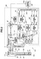
- the luminance signal processing system of the main body processing device 43 includes a contour correction portion 432, being connected to the CCD 21, for correcting a contour of an image pickup signal from the CCD 21, and a luminance signal processing portion 434 for generating a luminance signal from data corrected by the contour correction portion 432.
- the color signal processing system of the main body processing device 43 also includes sample hold circuits (S/H circuits) 433a to 433c, being connected to the CCD 21, for sampling an image pickup signal obtained by the CCD 21, for example, to generate an RGB signal, and a color signal processing portion 435, being connected to outputs of the S/H circuits 433a to 433c, for generating a color signal.
- S/H circuits sample hold circuits
- Spectral image generation has two generation modes.
- a first spectral image generation mode is a mode to prevent light flux from the lamp 15 from being transmitted through the light quantity limiting filter 16 similarly to the normal image generation.
- a second spectral image generation mode is a mode to cause light flux from the lamp 15 to transmit through the light quantity limiting filter 16.
- the control portion 42 sets a spectral image generation mode to the first spectral image generation mode.
- the control portion 42 controls driving of the filter insertion/removal driving portion 17, arranges the filter insertion/removal driving portion 17 on an optical path of light flux from the lamp 15, and sets the generation mode to the second spectral image generation mode.
- the second spectral image generation mode the light flux from the lamp 15 will be transmitted through the light quantity limiting filter 16.
- an invasion depth of light in a depth direction into the tissue in the body cavity 51 depends on a wavelength of the light.
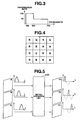
- short wavelength light like blue (B) light as shown in Fig. 8 only invades near a surface layer due to absorption characteristics and scattering characteristics in living tissue, is absorbed and scattered in that depth range, and light emitted from the surface is observed.
- Green (G) light of a longer wavelength than blue (B) light invades deeper than the range in which blue (B) light invades, is absorbed and scattered in that range, and light emitted from the surface is observed.
- Red (R) light of a longer wavelength than green (G) light reaches a deeper range.
- the above matrix processing in the matrix operation portion 436 is to create a spectral image signal by using a quasi-bandpass filter (matrix) previously generated as the above for a color image signal.
- the spectral image signals F1 to F3 are obtained using the quasi-bandpass filters F1 to F3 with discrete and narrowband spectral characteristics that can extract the desired deep layer tissue information as shown in Fig. 6 . Since respective wavelength regions of the quasi-bandpass filters F1 to F3 do not overlap as shown in Fig. 6 ,
- the color adjustment portion 440 assigns the spectral image signal F3 to the spectral color channel image signal Rch, the spectral image signal F2 to the spectral color channel image signal Gch, and the spectral image signal F1 to the spectral color channel image signal Bch, as an example of simplest color conversion, and outputs the signals to the RGB color channels R-(ch), G-(ch) and B-(ch) of the display monitor 106 via the display image generation portion 439.
- the spectral image signals F1 to F3 are generated through matrices corresponding to the quasi-bandpass filters F1 to F3, while the quasi-bandpass filters F1 to F3 are characterized by center wavelengths ⁇ 1, ⁇ 2 and ⁇ 3. That is, the main body processing device 43 sets one center wavelength ⁇ to decide one quasi-bandpass filter F, and generates a spectral image signal F based on the quasi-bandpass filter F.
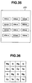
- the main body processing device 43 can simultaneously display a normal light observation image 210 and a colored color spectral image 211 on the observation monitor 106 by the display image generation portion 439, as shown in Fig. 21 .
- the display image generation portion 439 can display thumbnail images 221 to 226 of spectral images with the six center wavelengths being set in, for example, the above setting screen available to be used in coloring the color spectral image 211 in addition to the normal light observation image 210 and the color spectral image 211.
- FIG. 21 shows a state of the color spectral image 211 being generated through three spectral images with the center the wavelengths ⁇ 11, ⁇ 12 and ⁇ 13.
- Fig. 22 shows a state of the color spectral image 211 being generated through three spectral images with the center wavelengths ⁇ 12, ⁇ 21 and ⁇ 23.
- the thumbnail images of the three spectral images configuring the freeze color spectral image 241 are displayed in a different display form (for example, different luminance or color tone) from other thumbnail images.
- three spectral images configuring the freeze color spectral image 241 can be arbitrarily changed by selecting the thumbnail images 221 to 226 using the touch-sensitive panel function and operating a selection decision button 243 as shown in Fig. 27 .
- the color spectral image 241 of a moving image of the three spectral images selected from the thumbnail images 221 to 226 can be displayed by operating a confirmation button 244 using the touch-sensitive panel function.
- the color spectral image 241 of the moving image of the three spectral images selected from the thumbnail images 221 to 226 can also be automatically displayed only by an operation of the selection decision button 243, instead of providing the confirmation button 244.
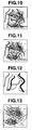
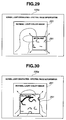
- the main body processing device 43 designates a spectral image display frame 281 on the normal light observation image 210 as shown in Fig. 29 , so that the device 43 can display a spectral image of the region by superposition in a region of the designated spectral image display frame 281.
- a size and position of the spectral image display frame 281 can be arbitrarily changed by the touch-sensitive panel function, as shown in Fig. 30 .
- configuration of a spectral image is set using a wavelength as a setting parameter, but the present invention is not limited thereto. Instead, the designation can be done using depth information being an invasion depth of light as a setting parameter, or the designation can be done using a function name such as blood vessel highlighting as a setting parameter.
- the main body 105 of the endoscope device according to the present embodiment is provided with a plurality of board slots 300 on a back surface into which function expansion substrates for function expansion can be inserted, as shown in Fig. 31 .
- the control portion 44 displays a menu window 260 as shown in Fig. 32 on the touch-sensitive panel 106a to deploy executable functions.
- default functions of the control portion 44 without a function expansion substrate being inserted can be classified to four basic functions, for example, the functions are switchable using tags 261 of menus 1, 2, 3 and 4 on the menu window 260.
- the menu window 260 includes menu tags 262 for a plurality of function expansion substrates in addition to the tags 261 of menus 1, 2, 3 and 4.
- the menu tags 262 are for empty menus, as shown in Fig. 33 .
- the control portion 44 can deploy an additional function menu window of functions of the inserted function expansion substrate from the menu window 260 through a tag 262a of a menu 5, as shown in Fig. 34 .
- a wavelength setting function can be assigned to a function key of a general keyboard.
- the light quantity limiting filter 16 is configured to be insertably removable on an optical path.
- the filter 16 can also be permanently provided on an optical path.
- a color filter provided for the CCD 21 can have similar spectral characteristics to a light quantity limiting filter, thereby omitting the light quantity limiting filter 16.
- the present embodiment differs from the first embodiment mainly in the light source portion 41 and the CCD 21.
- the CCD 21 is provided with the color filter shown in Fig. 4 , and a so-called simultaneous type is used in which the color filter generates a color signal.
- so-called frame sequential type is used for illuminating illumination light in an RGB order to generate a color signal.
- the light source portion 41 in the light source portion 41 according to the present embodiment, light via the lamp 15, the infrared cut filter 15a and the light quantity limiting filter 16 is transmitted through an RGB filter 23.
- the light quantity limiting filter 16 is insertably removable on an optical path.
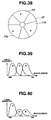
- the RGB rotating filter 23 is configured with an R filter portion 23r for transmitting R band light, a G filter portion 23g for transmitting G band light, and a B filter portion 23b for transmitting B band light, as shown in Fig. 38.
- Fig. 39 shows spectral characteristics of light transmitting the RGB rotating filter 23 in the first spectral image generation mode, i.e., when the light quantity limiting filter 16 is not on an optical path.
- Fig. 40 shows spectral characteristics of light being transmitted through the RGB rotating filter 23 in the second spectral image generation mode, i.e., when the light quantity limiting filter 16 is on an optical path.
- unnecessary infrared components of light flux outputted from the lamp 15 are cut in the infrared cut filter 15a, and light flux being transmitted through the infrared cut filter 15a selectively passes through the light quantity limiting filter 16 and is transmitted through the RGB rotating filter 23, so that the light flux is outputted from the light source portion as R, G and B illumination lights at each pre-determined time.
- the respective illumination lights reflect in a subject and received by the CCD 21.
- Signals obtained by the CCD 21 are distributed by a switch portion (not shown) provided for the main body 105 of the endoscope device depending on radiation time, and inputted to the S/H circuits 433a to 433c, respectively. That is, if illumination light is radiated from the light source portion 41 via an R filter, the signals obtained by the CCD 21 are inputted to the S/H circuit 433a.
- the other operation is similar to the first embodiment and will not be described.
- the rotating filter 23 is configured in a disc shape and has a double structure centering on a rotation axis as shown in Fig. 42 .
- an R filter portion 23r1 On an outside diameter part of the filter 23, an R filter portion 23r1, the G filter portion 23g1 and the B filter portion 23b1 are arranged that configure a first filter set to output frame sequential light with the spectral characteristics as shown in Fig. 39 .
- an R' filter portion 23r2, a G' filter portion 23g2 and a B filter portion 23b2 are arranged that configure a second filter set to output frame sequential light with the spectral characteristics as shown in Fig. 40 .
Landscapes
- Health & Medical Sciences (AREA)
- Life Sciences & Earth Sciences (AREA)
- Surgery (AREA)
- Engineering & Computer Science (AREA)
- Physics & Mathematics (AREA)
- Optics & Photonics (AREA)
- Biomedical Technology (AREA)
- Veterinary Medicine (AREA)
- Biophysics (AREA)
- Pathology (AREA)
- Radiology & Medical Imaging (AREA)
- Nuclear Medicine, Radiotherapy & Molecular Imaging (AREA)
- Public Health (AREA)
- Heart & Thoracic Surgery (AREA)
- Medical Informatics (AREA)
- Molecular Biology (AREA)
- Animal Behavior & Ethology (AREA)
- General Health & Medical Sciences (AREA)
- Signal Processing (AREA)
- Multimedia (AREA)
- Astronomy & Astrophysics (AREA)
- General Physics & Mathematics (AREA)
- Endoscopes (AREA)
- Instruments For Viewing The Inside Of Hollow Bodies (AREA)
- Closed-Circuit Television Systems (AREA)
Applications Claiming Priority (2)
| Application Number | Priority Date | Filing Date | Title |
|---|---|---|---|
| JP2006073183A JP4951256B2 (ja) | 2006-03-16 | 2006-03-16 | 生体観測装置 |
| PCT/JP2007/053088 WO2007108270A1 (ja) | 2006-03-16 | 2007-02-20 | 生体観測装置 |
Publications (3)
| Publication Number | Publication Date |
|---|---|
| EP1994875A1 EP1994875A1 (en) | 2008-11-26 |
| EP1994875A4 EP1994875A4 (en) | 2010-04-28 |
| EP1994875B1 true EP1994875B1 (en) | 2013-12-18 |
Family
ID=38522306
Family Applications (1)
| Application Number | Title | Priority Date | Filing Date |
|---|---|---|---|
| EP07714591.0A Expired - Fee Related EP1994875B1 (en) | 2006-03-16 | 2007-02-20 | Living body observation device |
Country Status (7)
| Country | Link |
|---|---|
| US (1) | US8581970B2 (ja) |
| EP (1) | EP1994875B1 (ja) |
| JP (1) | JP4951256B2 (ja) |
| KR (1) | KR101022585B1 (ja) |
| CN (1) | CN101400294B (ja) |
| BR (1) | BRPI0709580A2 (ja) |
| WO (1) | WO2007108270A1 (ja) |
Families Citing this family (45)
| Publication number | Priority date | Publication date | Assignee | Title |
|---|---|---|---|---|
| JP4849985B2 (ja) * | 2006-07-21 | 2012-01-11 | 富士フイルム株式会社 | 電子内視鏡システム |
| JP2009125411A (ja) * | 2007-11-27 | 2009-06-11 | Fujinon Corp | 内視鏡画像処理方法および装置ならびにこれを用いた内視鏡システム |
| JP5246643B2 (ja) * | 2007-12-19 | 2013-07-24 | 富士フイルム株式会社 | 撮像システムおよびプログラム |
| JP5039621B2 (ja) * | 2008-03-25 | 2012-10-03 | 富士フイルム株式会社 | 電子内視鏡装置 |
| JP2009240354A (ja) * | 2008-03-28 | 2009-10-22 | Fujinon Corp | 電子内視鏡装置 |
| JP5098030B2 (ja) * | 2008-04-02 | 2012-12-12 | 富士フイルム株式会社 | 撮像装置、撮像方法、およびプログラム |
| EP3501384A3 (en) | 2008-05-20 | 2019-10-16 | University Health Network | Method for fluorescence-based imaging and monitoring |
| JP5483522B2 (ja) * | 2008-08-12 | 2014-05-07 | 富士フイルム株式会社 | 画像取得装置 |
| JP2010051602A (ja) * | 2008-08-29 | 2010-03-11 | Fujifilm Corp | 電子内視鏡装置および方法並びにプログラム |
| JP5127639B2 (ja) | 2008-09-10 | 2013-01-23 | 富士フイルム株式会社 | 内視鏡システム、およびその作動方法 |
| JP5203861B2 (ja) * | 2008-09-10 | 2013-06-05 | 富士フイルム株式会社 | 内視鏡システム、およびその作動方法 |
| EP2345359A4 (en) * | 2008-10-17 | 2012-04-04 | Olympus Corp | Image generation device, endoscope system and image generation method |
| WO2010044432A1 (ja) * | 2008-10-17 | 2010-04-22 | オリンパスメディカルシステムズ株式会社 | 内視鏡システムおよび内視鏡画像処理装置 |
| JP2010213746A (ja) * | 2009-03-13 | 2010-09-30 | Fujifilm Corp | 内視鏡画像処理装置および方法ならびにプログラム |
| EP2386239A4 (en) | 2009-05-12 | 2012-08-15 | Olympus Medical Systems Corp | IN VIVO IMAGING SYSTEM OF THE SUBJECT AND IN VIVO INTRODUCTION DEVICE IN THE FIELD |
| JP2010279579A (ja) * | 2009-06-05 | 2010-12-16 | Fujifilm Corp | 画像取得方法および内視鏡装置 |
| JP5460506B2 (ja) | 2009-09-24 | 2014-04-02 | 富士フイルム株式会社 | 内視鏡装置の作動方法及び内視鏡装置 |
| JP5460507B2 (ja) * | 2009-09-24 | 2014-04-02 | 富士フイルム株式会社 | 内視鏡装置の作動方法及び内視鏡装置 |
| JP5541914B2 (ja) | 2009-12-28 | 2014-07-09 | オリンパス株式会社 | 画像処理装置、電子機器、プログラム及び内視鏡装置の作動方法 |
| DE112011100495T5 (de) * | 2010-02-10 | 2013-01-03 | Hoya Corporation | Elektronisches Endoskopsystem |
| US9420153B2 (en) | 2010-02-10 | 2016-08-16 | Hoya Corporation | Electronic endoscope system |
| JP5393534B2 (ja) * | 2010-02-26 | 2014-01-22 | Hoya株式会社 | 電子内視鏡装置 |
| JP5385188B2 (ja) * | 2010-03-26 | 2014-01-08 | 富士フイルム株式会社 | 電子内視鏡システム |
| JP5507376B2 (ja) * | 2010-07-28 | 2014-05-28 | 三洋電機株式会社 | 撮像装置 |
| JP5133386B2 (ja) * | 2010-10-12 | 2013-01-30 | 富士フイルム株式会社 | 内視鏡装置 |
| JP5639464B2 (ja) * | 2010-12-21 | 2014-12-10 | 富士フイルム株式会社 | 光計測システムおよび光計測システムの作動方法 |
| JP5649947B2 (ja) * | 2010-12-21 | 2015-01-07 | 富士フイルム株式会社 | 光計測システムおよび光計測システムの作動方法 |
| JP5550574B2 (ja) * | 2011-01-27 | 2014-07-16 | 富士フイルム株式会社 | 電子内視鏡システム |
| JP5274591B2 (ja) * | 2011-01-27 | 2013-08-28 | 富士フイルム株式会社 | 内視鏡システム、内視鏡システムのプロセッサ装置、及び内視鏡システムの作動方法 |
| JP5554253B2 (ja) * | 2011-01-27 | 2014-07-23 | 富士フイルム株式会社 | 電子内視鏡システム |
| US20130113904A1 (en) * | 2011-11-08 | 2013-05-09 | Capso Vision, Inc. | System and Method for Multiple Viewing-Window Display of Computed Spectral Images |
| JP5863435B2 (ja) * | 2011-12-15 | 2016-02-16 | Hoya株式会社 | 画像信号処理装置 |
| JP5872916B2 (ja) * | 2012-01-25 | 2016-03-01 | 富士フイルム株式会社 | 内視鏡システム、内視鏡システムのプロセッサ装置、及び内視鏡システムの作動方法 |
| JP5959987B2 (ja) * | 2012-08-15 | 2016-08-02 | Hoya株式会社 | 内視鏡システム |
| JP2014128394A (ja) * | 2012-12-28 | 2014-07-10 | Hoya Corp | 内視鏡装置 |
| KR101941907B1 (ko) * | 2013-01-03 | 2019-01-24 | 삼성전자주식회사 | 깊이 정보를 이용하는 내시경 및 깊이 정보를 이용하는 내시경에 의한 용종 검출 방법 |
| CN103284681A (zh) * | 2013-05-24 | 2013-09-11 | 中国科学院苏州生物医学工程技术研究所 | 一种血管内双光谱成像装置 |
| JP5930474B2 (ja) | 2013-09-27 | 2016-06-08 | 富士フイルム株式会社 | 内視鏡システム及びその作動方法 |
| WO2015151703A1 (ja) * | 2014-03-31 | 2015-10-08 | 富士フイルム株式会社 | 内視鏡システム及びその作動方法 |
| ES2894912T3 (es) | 2014-07-24 | 2022-02-16 | Univ Health Network | Recopilación y análisis de datos con fines de diagnóstico |
| JP6606817B2 (ja) * | 2014-09-26 | 2019-11-20 | セイコーエプソン株式会社 | 測定装置 |
| WO2016151062A1 (en) * | 2015-03-26 | 2016-09-29 | Koninklijke Philips N.V. | Device, system and method for illuminating a structure of interest inside a human or animal body |
| CN105306896B (zh) * | 2015-10-27 | 2018-07-10 | 杭州永控科技有限公司 | 基于光定位的案件卷宗移交方法及系统 |
| JP6133474B2 (ja) * | 2016-06-21 | 2017-05-24 | Hoya株式会社 | 内視鏡システム |
| WO2019171703A1 (ja) * | 2018-03-05 | 2019-09-12 | オリンパス株式会社 | 内視鏡システム |
Family Cites Families (11)
| Publication number | Priority date | Publication date | Assignee | Title |
|---|---|---|---|---|
| GB2068537B (en) * | 1980-02-04 | 1984-11-14 | Energy Conversion Devices Inc | Examining biological materials |
| US5751672A (en) | 1995-07-26 | 1998-05-12 | Sony Corporation | Compact disc changer utilizing disc database |
| US7892169B2 (en) * | 2000-07-21 | 2011-02-22 | Olympus Corporation | Endoscope apparatus |
| JP3583731B2 (ja) * | 2000-07-21 | 2004-11-04 | オリンパス株式会社 | 内視鏡装置および光源装置 |
| US6678398B2 (en) * | 2000-09-18 | 2004-01-13 | Sti Medical Systems, Inc. | Dual mode real-time screening and rapid full-area, selective-spectral, remote imaging and analysis device and process |
| JP2003093336A (ja) * | 2001-09-26 | 2003-04-02 | Toshiba Corp | 電子内視鏡装置 |
| US7252633B2 (en) * | 2002-10-18 | 2007-08-07 | Olympus Corporation | Remote controllable endoscope system |
| JP4294440B2 (ja) | 2003-10-30 | 2009-07-15 | オリンパス株式会社 | 画像処理装置 |
| JP4598178B2 (ja) * | 2003-12-25 | 2010-12-15 | Hoya株式会社 | 電子内視鏡用プロセッサ、及び電子内視鏡システム |
| JP2005198750A (ja) * | 2004-01-14 | 2005-07-28 | Pentax Corp | プロセッサおよび電子内視鏡システム |
| JP2005296200A (ja) * | 2004-04-08 | 2005-10-27 | Olympus Corp | 内視鏡用画像処理装置 |
-
2006
- 2006-03-16 JP JP2006073183A patent/JP4951256B2/ja active Active
-
2007
- 2007-02-20 BR BRPI0709580-5A patent/BRPI0709580A2/pt not_active IP Right Cessation
- 2007-02-20 WO PCT/JP2007/053088 patent/WO2007108270A1/ja active Application Filing
- 2007-02-20 EP EP07714591.0A patent/EP1994875B1/en not_active Expired - Fee Related
- 2007-02-20 KR KR1020087022311A patent/KR101022585B1/ko not_active IP Right Cessation
- 2007-02-20 CN CN2007800084664A patent/CN101400294B/zh active Active
-
2008
- 2008-09-15 US US12/210,672 patent/US8581970B2/en active Active
Also Published As
| Publication number | Publication date |
|---|---|
| KR101022585B1 (ko) | 2011-03-16 |
| US8581970B2 (en) | 2013-11-12 |
| US20090040298A1 (en) | 2009-02-12 |
| EP1994875A4 (en) | 2010-04-28 |
| JP2007244681A (ja) | 2007-09-27 |
| JP4951256B2 (ja) | 2012-06-13 |
| CN101400294A (zh) | 2009-04-01 |
| EP1994875A1 (en) | 2008-11-26 |
| WO2007108270A1 (ja) | 2007-09-27 |
| KR20080095280A (ko) | 2008-10-28 |
| CN101400294B (zh) | 2011-03-02 |
| BRPI0709580A2 (pt) | 2011-07-19 |
Similar Documents
| Publication | Publication Date | Title |
|---|---|---|
| EP1994875B1 (en) | Living body observation device | |
| EP1880658B9 (en) | Signal processing device for biological observation apparatus | |
| EP3437542B1 (en) | Image processing device, operation method for image processing device, and image processing program | |
| JP4504324B2 (ja) | 生体観測装置 | |
| JP6785948B2 (ja) | 医療用画像処理装置及び内視鏡システム並びに医療用画像処理装置の作動方法 | |
| RU2381737C2 (ru) | Устройство для наблюдения биологических объектов | |
| JP5977772B2 (ja) | 内視鏡システム、内視鏡システムのプロセッサ装置、内視鏡システムの作動方法、プロセッサ装置の作動方法 | |
| KR100988113B1 (ko) | 생체 관측 장치 | |
| JP5789280B2 (ja) | プロセッサ装置、内視鏡システム、及び内視鏡システムの作動方法 | |
| EP2775450B1 (en) | Image processing device and method for operating endoscope system | |
| JP7335399B2 (ja) | 医用画像処理装置及び内視鏡システム並びに医用画像処理装置の作動方法 | |
| CN111343898A (zh) | 内窥镜系统及其工作方法 | |
| US20170340273A1 (en) | Image processing device, living-body observation device, and image processing method | |
| US10003774B2 (en) | Image processing device and method for operating endoscope system | |
| US10285631B2 (en) | Light source device for endoscope and endoscope system | |
| JP6054806B2 (ja) | 画像処理装置及び内視鏡システムの作動方法 | |
| JP2018051364A (ja) | 内視鏡システム、内視鏡システムのプロセッサ装置、内視鏡システムの作動方法、プロセッサ装置の作動方法 | |
| US20200060531A1 (en) | Endoscope system, endoscope apparatus, light source apparatus, and method of operating endoscope system | |
| JP6616071B2 (ja) | 内視鏡用のプロセッサ装置、内視鏡用のプロセッサ装置の作動方法、内視鏡用の制御プログラム | |
| JP6669539B2 (ja) | 画像処理装置、画像処理装置の作動方法、および画像処理プログラム | |
| JP6272956B2 (ja) | 内視鏡システム、内視鏡システムのプロセッサ装置、内視鏡システムの作動方法、プロセッサ装置の作動方法 | |
| JP2006341076A (ja) | 生体観測装置用信号処理装置 | |
| CN114786560A (zh) | 内窥镜装置及观察方法 |
Legal Events
| Date | Code | Title | Description |
|---|---|---|---|
| PUAI | Public reference made under article 153(3) epc to a published international application that has entered the european phase |
Free format text: ORIGINAL CODE: 0009012 |
|
| 17P | Request for examination filed |
Effective date: 20080915 |
|
| AK | Designated contracting states |
Kind code of ref document: A1 Designated state(s): DE FR GB |
|
| DAX | Request for extension of the european patent (deleted) | ||
| RBV | Designated contracting states (corrected) |
Designated state(s): DE FR GB |
|
| A4 | Supplementary search report drawn up and despatched |
Effective date: 20100329 |
|
| 17Q | First examination report despatched |
Effective date: 20100714 |
|
| GRAP | Despatch of communication of intention to grant a patent |
Free format text: ORIGINAL CODE: EPIDOSNIGR1 |
|
| INTG | Intention to grant announced |
Effective date: 20130712 |
|
| GRAS | Grant fee paid |
Free format text: ORIGINAL CODE: EPIDOSNIGR3 |
|
| GRAA | (expected) grant |
Free format text: ORIGINAL CODE: 0009210 |
|
| AK | Designated contracting states |
Kind code of ref document: B1 Designated state(s): DE FR GB |
|
| REG | Reference to a national code |
Ref country code: GB Ref legal event code: FG4D |
|
| REG | Reference to a national code |
Ref country code: DE Ref legal event code: R096 Ref document number: 602007034311 Country of ref document: DE Effective date: 20140213 |
|
| REG | Reference to a national code |
Ref country code: DE Ref legal event code: R097 Ref document number: 602007034311 Country of ref document: DE |
|
| PLBE | No opposition filed within time limit |
Free format text: ORIGINAL CODE: 0009261 |
|
| STAA | Information on the status of an ep patent application or granted ep patent |
Free format text: STATUS: NO OPPOSITION FILED WITHIN TIME LIMIT |
|
| REG | Reference to a national code |
Ref country code: FR Ref legal event code: ST Effective date: 20141031 |
|
| 26N | No opposition filed |
Effective date: 20140919 |
|
| GBPC | Gb: european patent ceased through non-payment of renewal fee |
Effective date: 20140318 |
|
| REG | Reference to a national code |
Ref country code: DE Ref legal event code: R097 Ref document number: 602007034311 Country of ref document: DE Effective date: 20140919 |
|
| PG25 | Lapsed in a contracting state [announced via postgrant information from national office to epo] |
Ref country code: FR Free format text: LAPSE BECAUSE OF NON-PAYMENT OF DUE FEES Effective date: 20140228 Ref country code: GB Free format text: LAPSE BECAUSE OF NON-PAYMENT OF DUE FEES Effective date: 20140318 |
|
| REG | Reference to a national code |
Ref country code: DE Ref legal event code: R082 Ref document number: 602007034311 Country of ref document: DE Representative=s name: WUESTHOFF & WUESTHOFF, PATENTANWAELTE PARTG MB, DE Ref country code: DE Ref legal event code: R081 Ref document number: 602007034311 Country of ref document: DE Owner name: OLYMPUS CORPORATION, JP Free format text: FORMER OWNER: OLYMPUS MEDICAL SYSTEMS CORP., TOKYO, JP |
|
| PGFP | Annual fee paid to national office [announced via postgrant information from national office to epo] |
Ref country code: DE Payment date: 20190219 Year of fee payment: 13 |
|
| REG | Reference to a national code |
Ref country code: DE Ref legal event code: R119 Ref document number: 602007034311 Country of ref document: DE |
|
| PG25 | Lapsed in a contracting state [announced via postgrant information from national office to epo] |
Ref country code: DE Free format text: LAPSE BECAUSE OF NON-PAYMENT OF DUE FEES Effective date: 20200901 |