EP1994868A2 - Düsenanordnung für Staubsauger - Google Patents
Düsenanordnung für Staubsauger Download PDFInfo
- Publication number
- EP1994868A2 EP1994868A2 EP08001203A EP08001203A EP1994868A2 EP 1994868 A2 EP1994868 A2 EP 1994868A2 EP 08001203 A EP08001203 A EP 08001203A EP 08001203 A EP08001203 A EP 08001203A EP 1994868 A2 EP1994868 A2 EP 1994868A2
- Authority
- EP
- European Patent Office
- Prior art keywords
- nozzle assembly
- brush
- cleaned
- assembly body
- air inlet
- Prior art date
- Legal status (The legal status is an assumption and is not a legal conclusion. Google has not performed a legal analysis and makes no representation as to the accuracy of the status listed.)
- Granted
Links
- 239000000428 dust Substances 0.000 claims abstract description 35
- 230000008859 change Effects 0.000 claims abstract description 4
- 239000000463 material Substances 0.000 claims description 5
- 239000004033 plastic Substances 0.000 claims description 5
- 238000004140 cleaning Methods 0.000 description 8
- 239000002245 particle Substances 0.000 description 5
- 238000010276 construction Methods 0.000 description 3
- 230000004048 modification Effects 0.000 description 2
- 238000012986 modification Methods 0.000 description 2
- 210000004081 cilia Anatomy 0.000 description 1
- 239000004744 fabric Substances 0.000 description 1
- 238000013021 overheating Methods 0.000 description 1
- 230000002265 prevention Effects 0.000 description 1
- 230000008439 repair process Effects 0.000 description 1
- 238000007790 scraping Methods 0.000 description 1
Images


Classifications
-
- A—HUMAN NECESSITIES
- A47—FURNITURE; DOMESTIC ARTICLES OR APPLIANCES; COFFEE MILLS; SPICE MILLS; SUCTION CLEANERS IN GENERAL
- A47L—DOMESTIC WASHING OR CLEANING; SUCTION CLEANERS IN GENERAL
- A47L9/00—Details or accessories of suction cleaners, e.g. mechanical means for controlling the suction or for effecting pulsating action; Storing devices specially adapted to suction cleaners or parts thereof; Carrying-vehicles specially adapted for suction cleaners
- A47L9/02—Nozzles
- A47L9/04—Nozzles with driven brushes or agitators
- A47L9/0461—Dust-loosening tools, e.g. agitators, brushes
- A47L9/0488—Combinations or arrangements of several tools, e.g. edge cleaning tools
-
- A—HUMAN NECESSITIES
- A47—FURNITURE; DOMESTIC ARTICLES OR APPLIANCES; COFFEE MILLS; SPICE MILLS; SUCTION CLEANERS IN GENERAL
- A47L—DOMESTIC WASHING OR CLEANING; SUCTION CLEANERS IN GENERAL
- A47L9/00—Details or accessories of suction cleaners, e.g. mechanical means for controlling the suction or for effecting pulsating action; Storing devices specially adapted to suction cleaners or parts thereof; Carrying-vehicles specially adapted for suction cleaners
- A47L9/02—Nozzles
- A47L9/04—Nozzles with driven brushes or agitators
- A47L9/0494—Height adjustment of dust-loosening tools
-
- A—HUMAN NECESSITIES
- A47—FURNITURE; DOMESTIC ARTICLES OR APPLIANCES; COFFEE MILLS; SPICE MILLS; SUCTION CLEANERS IN GENERAL
- A47L—DOMESTIC WASHING OR CLEANING; SUCTION CLEANERS IN GENERAL
- A47L9/00—Details or accessories of suction cleaners, e.g. mechanical means for controlling the suction or for effecting pulsating action; Storing devices specially adapted to suction cleaners or parts thereof; Carrying-vehicles specially adapted for suction cleaners
- A47L9/02—Nozzles
- A47L9/06—Nozzles with fixed, e.g. adjustably fixed brushes or the like
-
- A—HUMAN NECESSITIES
- A47—FURNITURE; DOMESTIC ARTICLES OR APPLIANCES; COFFEE MILLS; SPICE MILLS; SUCTION CLEANERS IN GENERAL
- A47L—DOMESTIC WASHING OR CLEANING; SUCTION CLEANERS IN GENERAL
- A47L9/00—Details or accessories of suction cleaners, e.g. mechanical means for controlling the suction or for effecting pulsating action; Storing devices specially adapted to suction cleaners or parts thereof; Carrying-vehicles specially adapted for suction cleaners
- A47L9/24—Hoses or pipes; Hose or pipe couplings
Definitions
- the present disclosure relates to a vacuum cleaner. More particularly, the present disclosure relates to a nozzle assembly of a vacuum cleaner, which comes in contact with a surface to be cleaned to draw in dust or dirt with air from the surface to be cleaned.
- a vacuum cleaner is provided with a nozzle assembly capable of drawing in dust or dirt from a surface to be cleaned.
- a nozzle assembly draws in the dirt or the dust from the surface to be cleaned by a suction force generated from a suction motor mounted in a cleaner body in a state where it comes in contact with the surface to be cleaned.
- Such a conventional nozzle assembly has a drum brush disposed in an air inlet to scrape off the dust or dirt adhered to the surface to be cleaned thus to efficiently brush away the dust or dirt therefrom.
- the drum brush is rotated by a motor mounted in the nozzle assembly or by a kinetic energy of drawn-in air.
- a brush member or blade projected from an outer circumferential surface of the drum brush scrapes against the surface to be cleaned while coming in rotation contact therewith.
- the conventional nozzle assembly is provided with a connecting unit to join or separate an extended tube of a cleaner body to or from the nozzle assembly.
- One of such conventional connecting units include a ring connector installed in the extended tube, and a connecting pipe formed on the nozzle assembly to have a diameter larger than that of the extended tube thus to accommodate the extended tube.
- the ring connector has a fixing protrusion projected outward from an outer circumferential surface of the extended tube through an inserting hole of the extended tube, and the connecting pipe has a fixing hole formed in a position corresponding to the inserting hole of the extended tube to accommodate the fixing protrusion. Accordingly, if a user wants to join the extended tube of the cleaner body to the nozzle assembly, she or he inserts the extended tube into the connecting pipe.
- the fixing protrusion is locked in the fixing hole and thus the extended tube and the nozzle assembly are joined to each other.
- she or he pushes the fixing protrusion with one hand.
- the ring connector is deformed to allow the fixing protrusion to push in toward the inside of the connecting pipe, and thus the locking connection between the extended tube and the nozzle assembly is released. Under this state, when the user pulls the extended tube with the other hand, the extended tube is separated from the connecting pipe.
- the conventional nozzle assembly is configured, so that a nozzle assembly body is formed as a single body of plastic material. Accordingly, a problem may occur, in that in cleaning, the nozzle assembly body is easily damaged or scratched when it comes in collision with an external structure, such as an obstacle.
- an aspect of the present disclosure is to address at least the above problems and/or disadvantages and to provide at least the advantages described below. Accordingly, an aspect of the present disclosure is to provide a nozzle assembly of a vacuum cleaner capable of more efficiently cleaning dust or dirt, which is firmly stuck to a surface to be cleaned.
- Another aspect of the present disclosure is to provide a nozzle assembly of a vacuum cleaner having a connecting unit capable of being easily joined to and separated from a connecting part of a cleaner body.
- Another aspect of the present disclosure is to provide a nozzle assembly of a vacuum cleaner having various additional functions, thereby allowing the nozzle assembly to be easily used.
- a nozzle assembly of a vacuum cleaner includes a nozzle assembly body having an air inlet and an air outlet, a drum brush unit disposed in the nozzle assembly body in the vicinity of the air inlet, and having a drum brush disposed to brush away dirt or dust adhered to a surface to be cleaned while coming in rotation contact therewith, and a movable brush unit disposed in at least one of the front and the rear of the air inlet on an undersurface of the nozzle assembly body to pivot in an opposite direction to a moving direction of the nozzle assembly body thus to change a contacting angle to the surface to be cleaned in the range of a predetermined angle and then to brush away dirt or dust adhered to the surface to be cleaned, in moving of the nozzle assembly body.
- the movable brush unit may include a first movable brush member disposed in front of the air inlet, and a second movable brush member disposed in the rear of the air inlet.
- Each of the first and the second movable brush members may include a supporting part rotatably supported in a first or a second mounting groove formed in the undersurface of the nozzle assembly body adjacent to the front or the rear of the air inlet and having a brush attached to an undersurface thereof, and at least one contact rotating part disposed on the undersurface of the supporting part to come in contact with the surface to be cleaned thus to rotate the supporting part in the opposite direction to the moving direction of the nozzle assembly body, in the moving of the nozzle assembly body.
- the supporting part may have a plurality of rotation supporting surfaces rotatably supported in a spaced-apart relation to each other by a plurality of hinge brackets disposed in the first or the second mounting groove.
- the contact rotating part may include a cam fixed on the undersurface of the supporting part, so that a rotating angle thereof is restricted in the predetermined angle by a front wall surface and a rear wall surface of the first or the second mounting groove.
- the cam is formed in a V-lettered shape having first and second contacting surfaces formed, so that when one is rotated coming in contact with the surface to be cleaned, the other comes in contact with the front wall surface or the rear wall surface of the corresponding first or second mounting groove to restrict a rotation of the cam.
- the predetermined angle is an angle of 30 degrees.
- both ends of the supporting part of the first movable brush member may be bent and extended toward both sides of the air inlet.
- the nozzle assembly body at both sides thereof has guide grooves formed to guide the both ends of the supporting part to rotate in the predetermined angle.
- the nozzle assembly body may have a drum brush casing formed of one of a rubber and a plastic material of PVC series to surround the drum brush in a front thereof.
- the drum brush casing may have a transparent window to expose the drum brush to the outside thus to perceive a condition of the drum brush.
- the nozzle assembly may further include a connecting unit.
- the connecting unit includes a connecting pipe connected with an air passage of the nozzle assembly body and projected upward from an upper surface of the nozzle assembly body, a push lever rotatably supported on a fixing mount formed on one side of the connecting pipe and urged to come in contact with the connecting pipe by an elastic spring, and a locking pin formed on one surface of the push lever opposed to the connecting pipe and inserted into locking holes of the connecting pipe and the connecting part.
- the nozzle assembly may further include a height adjusting unit.
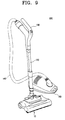
- FIG. 9 is a perspective view exemplifying an example of a vacuum cleaner 100 to which a nozzle assembly 10 according to an exemplary embodiment of the present disclosure is applied
- the vacuum cleaner 100 includes a nozzle assembly 10 to draw in air laid with dust or dirt, a telescopically extended tube 120 connected to the nozzle assembly 10, an operating handle 130, a suction hose 140 connected to the operating handle 130, and a cleaner body 150 connected to the suction hose 140 and divided into a dust separating chamber (not illustrated) and a motor chamber (not illustrated).
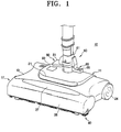
- FIGS. 1 , 2 and 3 are a perspective view, a top plan view and a bottom view exemplifying the nozzle assembly 10 of the vacuum cleaner according to the exemplary embodiment of the present disclosure.
- the nozzle assembly 10 of the according to the exemplary embodiment of the present disclosure includes a nozzle assembly body 11, a drum brush unit 17, a movable brush unit 40, a connecting unit 60, and a height adjusting unit 80.
- the nozzle assembly body 11 is made up of upper and lower casings 13 and 14.
- the upper and the lower casings 13 and 14 are joined with each other by screws and the like.
- an air passage (not illustrated), which is connected to an air inlet 18 (see FIG. 3 ) formed in the drum brush unit 17. Accordingly, when a vacuum motor (not illustrated) mounted in the cleaner body 150 generates a suction force, dust or dirt along with air is drawn in through the air inlet 18, and flown into the cleaner body 150 through an air outlet of the connecting unit 60 located in the rear of the nozzle assembly body 11 via the air passage of the upper and the lower casings 13 and 14.
- a driving motor (not illustrated), which drives a drum brush 19, is disposed in the upper and the lower casings 13 and 14 of the nozzle assembly body 11.
- a turbine which is rotated by the drawn-in air, can be disposed in the upper and the lower casings 13 and 14.
- a lamp 21 is disposed in the middle of the upper casing 13, and to easily move the nozzle assembly 10, a pair of wheels 24 are installed in the rear of the upper and the lower casings 13 and 14.
- the drum brush unit 17 includes a drum brush casing 26, and a drum brush 19.
- the drum brush casing 26 has the drum brush 19 disposed therein.
- the drum brush casing 26 is made up of a member separately formed from the upper casing 13 of the nozzle assembly body 11. To prevent the drum brush casing 26 from being damaged or scratched in collision with an external structure, such as an obstacle, it is formed of a rubber or a plastic material of PVC series. At this time, preferably, but not necessarily, the drum brush casing 26 has a transparent window 27 formed in a longitudinal direction in an upper surface thereof to expose the drum brush 19 to the outside thus to allow a user to perceive a condition of the drum brush 19.
- the air inlet 18 is formed in the lower casing 14 of the nozzle assembly body 11 joined with the drum brush casing 26, so that it can draw in the dust or dirt and the air.
- a plurality of ribs 25 is formed to cross the air inlet 18.
- the drum brush 19 strikes a surface to be cleaned in a tangential direction while coming in rotation contact with the surface to be cleaned and thus brushes away the dust or dirt adhered to the surface to be cleaned.
- the drum brush 19 is formed in the form of a drum, and has a plurality of furs or blade members 19a implanted in an approximately spiral shape on an outer circumferential surface thereof.
- the drum brush 19 is rotatably disposed in the lower casing 14.
- the drum brush 19 may be connected to the driving motor described above.
- the movable brush unit 40 pivots in an opposite direction to a moving direction of the nozzle assembly body 11 thus to change a contacting angle to the surface to be cleaned in the range of a predetermined angle and then brushes away dirt or dust adhered to the surface to be cleaned.
- the movable brush unit 40 includes first and second movable brush members 41 and 43 disposed in the vicinity of the air inlet 18 of the lower casing 14 of the nozzle assembly body 11.
- the first movable brush member 41 is located in front of the air inlet 18, and the second movable brush member 43 is located in the rear of the air inlet 18.
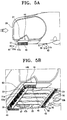
- the first movable brush member 41 which brushes or scrapes away the dust or dirt, such as particles, a hair, fur of pet or the like, adhered to the surface to be cleaned, is made up of a supporting part 44 and two contact rotating parts 50.
- the supporting part 44 is formed in the form of an elongated bar having a brush 45 attached on an undersurface thereof.
- the brush 45 is formed of a rubber plate having a plurality of protrusions.
- the supporting part 44 is rotatably supported in a first mounting groove 47 formed in an undersurface of the lower casing 14 of the nozzle assembly body 11 adjacent to the front of the air inlet 18.
- the supporting part 44 has four rotation supporting surfaces 48 formed in a spaced-apart relation to each other.
- the four rotation supporting surfaces 48 are rotatably supported by four hinge brackets 49 disposed in the first mounting groove 47, respectively. At this time, spaces above the rotation supporting surfaces 48 form spaces through which due to the suction force of the suction motor of the cleaner body 150, relatively dust or dirt draws in and passes, respectively.
- the rotation supporting surfaces 48 can be rotatably supported by four hinge protrusions (not illustrated) projected inside the first mounting groove 47 from an upper part of a front wall surface 47a or a rear wall surface 47b of the first mounting groove 47, instead of the hinge brackets 49.
- Both ends 44a and 44b of the supporting part 44 are bent and extended toward both sides of the air inlet 18 to brush or scrape away the dust or dirt adhered to the surface to be cleaned on the both sides of the air inlet 18.
- guide grooves 31 are formed on both sides of the drum brush casings 26 of the nozzle assembly body 11.
- the two contact rotating parts 50 are fixed to an undersurface of the supporting part 44 adjacent to the rotation supporting surfaces 48 located in the vicinity of the both ends 44a and 44b of the supporting part 44, so that in the moving of the nozzle assembly body 11, they come in contact with the surface to be cleaned thus to rotate the supporting part 44 in the opposite direction to the moving direction of the nozzle assembly body 11.
- Each of the two contact rotating parts 50 can be formed of a cam 51 fixed on the undersurface of the supporting part 44, so that a rotating angle thereof is restricted in the predetermined angle, that is, the angle of approximately 30 degrees, by the front wall surface 47a and the rear wall surface 47b of the first mounting groove 47.
- the cam 51 is formed of a rubber member of a V-lettered shape having first and second contacting surfaces 51 a and 51 b formed, so that when one is rotated coming in contact with the surface to be cleaned, the other comes in contact with the corresponding front or the rear wall surface 47a or 47b of the first mounting groove 47 to restrict a rotation of the cam 51.
- an elastic force of the first and the second contacting surfaces 51a and 51b, an angle between the first and the second contacting surfaces 51a and 51 b, and distances between the first and the second contacting surfaces 51a and 51 b and the front and the rear wall surfaces 47a and 47b are set, so that the cam 51 of the contact rotating parts 50 is moved in the range of the predetermined angle, that is, the angle of 30 approximately degrees when it is rotated in contact with the surface to be cleaned.
- the second movable brush member 43 has the same construction as that of the first movable brush member 41, except that it is installed in a second mounting groove 53 formed on the undersurface of the lower casing 14 of the nozzle assembly body 11 adjacent to the rear of the air inlet 18 and both ends of the supporting part 44 are not bent and extended toward both sides of the drum brush 19, but formed in an I-lettered shape. Accordingly, a detailed description on the construction of the second movable brush member 43 will be omitted.
- the connecting unit 60 is provided with a connecting pipe 61 projected upward from an upper surface of the upper casing 13 of the nozzle assembly body 11 in the middle of the rear of the upper casing 13.
- the connecting pipe 61 is connected with the air passage of the upper and the lower casings 13 and 14 of the nozzle assembly body 11 to form an air outlet, and has a wire (not illustrated) disposed therein so as not to be exposed to the outside.
- the wire is connected between the driving motor of the nozzle assembly body 11 and a terminal of a female socket (not illustrated) formed in an upper end of the connecting pipe 61.
- the female socket is joined with a male socket 123 formed in a lower end 120a of the extended tube 120 when the lower end 120a of the extended tube 120 is inserted into and assembled with the connecting pipe 61.
- a locking part 65 On one side of the connecting pipe 61 is disposed a locking part 65 to lock the lower end 120a of the extended tube 120 to the connecting pipe 61.
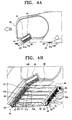
- the locking part 65 is provided with an L-lettered push lever 66 rotatably supported on an axis 64 (see FIG. 6 ) of a fixing mount 62 formed on the one side of the connecting pipe 61.
- the push lever 66 is urged in a direction where an upper end 66a thereof comes in contact with the connecting pipe 61, by an elastic spring, such as a torsion spring, installed on the axis 64.
- a locking pin 67 is formed on one surface of the upper end 66a of the push lever 66 opposed to the connecting pipe 61, and is inserted into a locking hole 61 a of the connecting pipe 61 and a locking hole 120b (see FIG. 7A ) of the lower end 120a of the extended tube 120.
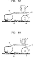
- a user wants to join the lower end 120a of the extended tube 120 to the connecting pipe 61, she or he inserts the male socket 123 formed in the lower end 120a of the extended tube 120 into the female socket formed in the upper end of the connecting pipe 61 in a direction of arrow B, as illustrated in 6, in a state where she or he pushes the push lever 66 in a direction of arrow A of FIG. 6 with her or his foot, as illustrated in FIG. 7A . And then, the user takes away her or his foot from the push lever 66 to remove a force applied on the push lever 66.
- the locking pin 67 of the push lever 66 is inserted in turn into the locking hole 61 a of the connecting pipe 61 and the locking hole 120b of the lower end 120a of the extended tube 120, so that it locks the lower end 120a of the extended tube 120 in the upper end of the connecting pipe 61, as illustrated in FIG. 7B .
- the nozzle assembly 10 of the present disclosure further includes a height adjusting unit 80.
- the height adjusting unit 80 is provided with a height adjusting button 81, a lifting and lowering part (not illustrated) and a display part 83.
- the height adjusting button 81 is projected upward from the upper casing 13 in the vicinity of the connecting pipe 61 of the connecting unit 60, so that the user can push it with her or his foot.
- the lifting and lowering part lifts or lowers a wheel shaft 87 to which subsidiary wheels 23 are rotatably joined, in a plurality of steps, for example, four heights of high (HI), medium (MED), low (LO) and extra low (XLO), through a power transmitting part (not illustrated) according to the operation of the height adjusting button 81 by the user.
- the display part 83 displays the plurality of steps, that is, the four heights of high (HI), medium (MED), low (LO) and extra low (XLO), to which the wheel shaft 87 is lifted or lowered by the lifting and lowering part according to the operation of the height adjusting button 81. Since constructions and operations of the height adjusting unit 80 described above are the same as those of the conventional ones, detailed descriptions thereof will be omitted.
- a reset switch 96 for overheating prevention.
- the reset switch 96 is used for re-operating the driving motor after the large dirt is removed.
- the surface to be cleaned is, for example, a flat floor.
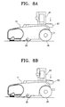
- the user pushes the height adjusting button 81 with her or his foot, and thus adjusts a height of the drum brush unit 17 of the nozzle assembly 10 to a height of extra low (XLO) or low (LO) adapted to clean the flat floor, as illustrated in FIGS. 8A and 8B .
- XLO extra low
- LO low
- the user moves the nozzle assembly 10 along the surface to be cleaned.
- the first contact surfaces 51a of the cams 51 of the first and the second movable brush members 41 and 43 come in contact with the surface to be cleaned and rotates by a predetermined angle, for example, an angle of approximately 30 degrees, in a counterclockwise direction due to a friction force thereof to the surface to be cleaned, until the second contact surfaces 51 b are pushed no longer coming in contact with the rear wall surfaces 47b and 53b of the first and the second mounting grooves 47 and 53, respectively.
- the supporting parts 44 of the first and the second movable brush members 41 and 43 which fix the cams 51, are also rotated by the angle of approximately 30 degrees in the counterclockwise direction.
- the both ends 44a and 44b of the supporting part 44 of the first movable brush member 41 bent and extended toward the both sides of the air inlet 18 are additionally restrained from moving, by the guide groove 31. Accordingly, the brushes 45 of the first and the second movable brush members 41 and 43 come in contact with the surface to be cleaned in a state where it is inclined rearward by the angle of approximately 30 degrees.
- the brushes 45 do not push out dust or dirt, such as particles, adhered to the surface to be cleaned toward the outside of the nozzle assembly body 11, but scrape off only dirt, such as a hair or fur of a pet, stuck to the surface to be cleaned.
- large dust or dirt adhered to the surface to be cleaned is drawn in toward the air inlet 18 through the spaces above the rotation supporting surfaces 48 of the supporting parts 44 of the first and the second movable brush members 41 and 43 by the suction force of the driving motor of the cleaner body 150.
- the supporting part 44 of the second movable brush member 43 is rotated by the predetermined angle, that is, the angle of approximately 30 degrees, in the clockwise direction until the first contact surfaces 51 a are pushed no longer coming in contact with the front wall surface 53a of the second mounting grooves 53.
- the brush 45 of the supporting part 44 of the second movable brush members 43 comes in contact with the surface to be cleaned in a state where it is inclined forward by the angle of approximately 30 degrees and thus scrapes off only dirt, such as a hair or fur of a pet, stuck to the surface to be cleaned.
- the dust or dirt, such as the particles, the hair or the fur of a pet, firstly brushed or scraped away from the surface to be cleaned by the first and the second movable brush members 41 and 43 as described above are flowed into the cleaner body 150 through the air inlet 18, the extended tube 120 and the suction hose 140 by the suction force of the suction motor in the cleaner body 150, together with dust or dirt, such as particles, a hair or fur of a pet, secondly brushed or scraped away from the surface to be cleaned by the drum brush 19 rotating by the driving motor.
- the air flowed into the cleaner body 150 separates the dust or dirt therefrom in the dust separating chamber and then discharges to the outside through the motor chamber.
- the user wants to adjust the height of the drum brush unit 17 of the nozzle assembly 10 to a height of medium (MED) or high (HI) adapted to clean a carpet as illustrated in FIGS. 8C and 8D , she or he pushes the height adjusting button 81 with her or his foot, and thus adjusts the height of the drum brush unit 17 to the height of height of medium (MED) or high (HI).
- MED medium
- HI high
- the user wants to separate the nozzle assembly 10 from the extended tube 120, she or he pushes the push lever 66 in a direction of arrow A of FIG. 6 with her or his foot, and then pulls the lower end 120a of the extended tube 120 in a direction of arrow C of FIG. 7A , as described with reference to FIG. 6 through 7B . As a result, the nozzle assembly 10 is separated from the extended tube 120.
- the user After repairing the nozzle assembly 10, if the user wants to join the nozzle assembly 10 to the extended tube 120 again, she or he inserts the lower end 120a of the extended tube 120 into the upper end of the connecting pipe 61 in a direction of arrow B of FIG. 7A , in a state where she or he pushes the push lever 66 in the direction of arrow A of FIG. 6 with her or his foot. And then, the user takes away her or his foot from the push lever 66 to remove a force applied on the push lever 66. As a result, the locking pin 67 of the push lever 66 is inserted in turn into the locking holes 61 a and 120b, and thus the lower end 120a of the extended tube 120 is locked in the upper end of the connecting pipe 61.
- the nozzle assembly of the vacuum cleaner has the movable brush unit installed in the front and the rear of the air inlet, that is, the drum brush. Accordingly, the nozzle assembly of the vacuum cleaner according to the exemplary embodiment of the present disclosure can firstly scrape off the dust or dirt, particularly, the hair or the fur of a pet, which is not separate from the surface to be cleaned well, through the movable brush unit and secondly brush away and scatter the scraped dust or dirt through the drum brush to be drawn into the nozzle assembly, thereby improving cleaning efficiency for the dust or dirt.
- the nozzle assembly of the vacuum cleaner according to the exemplary embodiment of the present disclosure has the connecting unit configured, so that the user can join or separate the nozzle assembly body to or from the connecting part, that is, the lower end of the extended tube of the cleaner body only by inserting or pulling out the extended tube into or from the connecting pipe in the state where she or he pushes the push lever with her or his foot. Accordingly, the nozzle assembly of the vacuum cleaner according to the exemplary embodiment of the present disclosure is advantageous in that the user can easily assemble or disassemble the nozzle assembly body to or from the extended tube of the cleaner body.
- the nozzle assembly of the vacuum cleaner according to the exemplary embodiment of the present disclosure adjusts the height of the drum brush unit only by pushing the height adjusting button, it is convenient to use.
- the nozzle assembly of the vacuum cleaner according to the exemplary embodiment of the present disclosure can smoothly rotate the drum brush in concert with the state or the kind of the surface to be cleaned, thereby maximizing the cleaning efficiency.
- the nozzle assembly of the vacuum cleaner according to the exemplary embodiment of the present disclosure is configured, so that the nozzle assembly body has the drum brush casing formed of the rubber or the plastic material of the PVC series. Accordingly, the nozzle assembly of the vacuum cleaner according to the exemplary embodiment of the present disclosure can prevent the nozzle assembly body from being damaged or scratched in a collision with the external structure, such as the obstacle during the cleaning operation.
Landscapes
- Engineering & Computer Science (AREA)
- Mechanical Engineering (AREA)
- Nozzles For Electric Vacuum Cleaners (AREA)
Applications Claiming Priority (1)
| Application Number | Priority Date | Filing Date | Title |
|---|---|---|---|
| KR1020070050388A KR101349202B1 (ko) | 2007-05-23 | 2007-05-23 | 진공청소기용 노즐조립체 |
Publications (3)
| Publication Number | Publication Date |
|---|---|
| EP1994868A2 true EP1994868A2 (de) | 2008-11-26 |
| EP1994868A3 EP1994868A3 (de) | 2009-12-30 |
| EP1994868B1 EP1994868B1 (de) | 2010-12-22 |
Family
ID=39646903
Family Applications (1)
| Application Number | Title | Priority Date | Filing Date |
|---|---|---|---|
| EP08001203A Expired - Fee Related EP1994868B1 (de) | 2007-05-23 | 2008-01-23 | Düsenanordnung für Staubsauger |
Country Status (6)
| Country | Link |
|---|---|
| US (1) | US7549190B2 (de) |
| EP (1) | EP1994868B1 (de) |
| KR (1) | KR101349202B1 (de) |
| CN (1) | CN101310666B (de) |
| AU (1) | AU2008200517B2 (de) |
| DE (1) | DE602008004007D1 (de) |
Cited By (8)
| Publication number | Priority date | Publication date | Assignee | Title |
|---|---|---|---|---|
| CN106793900A (zh) * | 2014-10-13 | 2017-05-31 | 阿尔弗雷德·凯驰两合公司 | 表面清洁机 |
| CN107142885A (zh) * | 2017-06-13 | 2017-09-08 | 浙江工业大学 | 适用于多类型路面的自动清扫机构 |
| US10349797B2 (en) | 2014-10-13 | 2019-07-16 | Alfred Kärcher SE & Co. KG | Surface-cleaning machine |
| US10786130B2 (en) | 2013-12-12 | 2020-09-29 | Alfred Kärcher SE & Co. KG | Floor cleaning machine |
| US10881258B2 (en) | 2014-10-13 | 2021-01-05 | Alfred Kärcher SE & Co. KG | Surface cleaning machine and method for operating a surface cleaning machine |
| WO2021016024A1 (en) * | 2019-07-19 | 2021-01-28 | Techtronic Cordless Gp | Floor cleaner |
| US10959590B2 (en) | 2015-10-12 | 2021-03-30 | Alfred Kärcher SE & Co. KG | Surface cleaning machine |
| US11058274B2 (en) | 2016-03-09 | 2021-07-13 | Alfred Kärcher SE & Co. KG | Surface cleaning machine |
Families Citing this family (30)
| Publication number | Priority date | Publication date | Assignee | Title |
|---|---|---|---|---|
| JP4680704B2 (ja) * | 2005-07-19 | 2011-05-11 | パナソニック株式会社 | 基板クリーニング装置、及び基板搬送装置 |
| US10117553B2 (en) | 2008-03-17 | 2018-11-06 | Aktiebolaget Electrolux | Cleaning nozzle for a vacuum cleaner |
| CN103549921B (zh) | 2008-03-17 | 2017-01-11 | 伊莱克斯家用产品有限公司 | 具有清洁部件的搅拌器 |
| US9820626B2 (en) | 2008-03-17 | 2017-11-21 | Aktiebolaget Electrolux | Actuator mechanism for a brushroll cleaner |
| WO2010093073A1 (ko) * | 2009-02-12 | 2010-08-19 | 엘지전자 주식회사 | 진공 청소기 |
| CN102188191B (zh) * | 2010-03-10 | 2015-11-18 | 乐金电子(天津)电器有限公司 | 吸尘器 |
| US9072415B2 (en) | 2010-11-05 | 2015-07-07 | Bissell Homecare, Inc. | Bare floor vacuum cleaner |
| EP2747626B1 (de) * | 2011-08-23 | 2017-05-03 | Koninklijke Philips N.V. | Reinigungsvorrichtung zur reinigung einer oberfläche mit einer bürste und rakelelement |
| AU2012216246B2 (en) | 2011-08-23 | 2014-03-27 | Bissell Inc. | Auxiliary suction nozzle and port for vacuum cleaner |
| US9314140B2 (en) | 2011-10-26 | 2016-04-19 | Aktiebolaget Electrolux | Cleaning nozzle for a vacuum cleaner |
| US9993847B2 (en) | 2012-02-02 | 2018-06-12 | Aktiebolaget Electrolux | Cleaning arrangement for a nozzle of a vacuum cleaner |
| KR101354675B1 (ko) * | 2012-04-23 | 2014-01-27 | 주식회사코네트인더스트리 | 진공청소기의 흡입장치 |
| US9345371B2 (en) | 2012-12-12 | 2016-05-24 | Electrolux Home Care Products, Inc. | Vacuum cleaner base assembly |
| US20140157543A1 (en) | 2012-12-12 | 2014-06-12 | Electrolux Home Care Products, Inc. | Vacuum cleaner base assembly |
| US10045672B2 (en) | 2012-12-21 | 2018-08-14 | Aktiebolaget Electrolux | Cleaning arrangement for a rotatable member of a vacuum cleaner, cleaner nozzle, vacuum cleaner and cleaning unit |
| AU2014100004A4 (en) * | 2013-01-11 | 2014-01-30 | Bissell Inc. | Vacuum cleaner |
| US9072416B2 (en) | 2013-03-15 | 2015-07-07 | Aktiebolaget Electrolux | Vacuum cleaner agitator cleaner with brushroll lifting mechanism |
| EP3289946B1 (de) | 2013-05-02 | 2021-03-31 | Aktiebolaget Electrolux | Reinigungsdüse für einen staubsauger |
| GB201313707D0 (en) * | 2013-07-31 | 2013-09-11 | Dyson Technology Ltd | Cleaner head for a vacuum cleaner |
| US9622631B2 (en) * | 2013-09-18 | 2017-04-18 | Techtronic Floor Care Technology Limited | Surface cleaning nozzle adjustment apparatus with adjustable blade assembly |
| CN103465699B (zh) * | 2013-09-25 | 2016-05-11 | 温州大学 | 基于圆柱滚刷和气旋集尘装置的黑板清洁方法及黑板擦 |
| CN107049152B (zh) * | 2017-03-31 | 2022-07-29 | 苏州爱普电器有限公司 | 用于地面清洁装置的搅动刷 |
| DE102017112794A1 (de) * | 2017-06-09 | 2018-12-13 | Vorwerk & Co. Interholding Gmbh | Verfahren zum Betrieb eines sich selbsttätig fortbewegenden Bodenbearbeitungsgerätes |
| EP3524111A1 (de) * | 2018-02-08 | 2019-08-14 | Koninklijke Philips N.V. | Staubsaugerdüse |
| CN108577669B (zh) * | 2018-06-01 | 2023-12-19 | 追觅科技(苏州)有限公司 | 吸尘器及其地刷 |
| JP6993055B2 (ja) * | 2018-07-10 | 2022-01-13 | 新東工業株式会社 | 金型成形面処理装置 |
| KR102267510B1 (ko) * | 2019-12-03 | 2021-06-18 | 엘지전자 주식회사 | 진공 청소기 |
| WO2022062562A1 (zh) * | 2020-09-22 | 2022-03-31 | 追觅创新科技(苏州)有限公司 | 转接头及清洁装置 |
| CN112315392B (zh) * | 2020-10-27 | 2021-12-17 | 江苏美的清洁电器股份有限公司 | 地刷以及清洁设备 |
| CN114224235A (zh) * | 2022-01-06 | 2022-03-25 | 帝舍智能科技(武汉)有限公司 | 一种拖扫一体清洁工具及控制方法 |
Citations (1)
| Publication number | Priority date | Publication date | Assignee | Title |
|---|---|---|---|---|
| EP0649625A2 (de) | 1993-10-22 | 1995-04-26 | Sharp Kabushiki Kaisha | Elektrischer Staubsauger |
Family Cites Families (16)
| Publication number | Priority date | Publication date | Assignee | Title |
|---|---|---|---|---|
| US3220043A (en) * | 1962-03-19 | 1965-11-30 | Electrolux Corp | Self propelled floor treating machine |
| US4700429A (en) * | 1986-10-23 | 1987-10-20 | Whirlpool Corporation | Quick release wand for cannister vacuum cleaner |
| SE505115C2 (sv) * | 1995-10-27 | 1997-06-30 | Electrolux Ab | Dammsugarmunstycke innefattande ett borstmunstycke och förfarande för att åstadkomma sugning utefter borstmunstyckets, i rörelseriktningen sett, främre kant |
| KR200203882Y1 (ko) * | 1998-11-21 | 2000-12-01 | 송영소 | 진공청소기용 흡인구 |
| US6289552B1 (en) * | 1999-07-16 | 2001-09-18 | Matsushita Electric Corporation Of America | Vacuum cleaner with dual agitator windows |
| GB0023732D0 (en) * | 2000-09-28 | 2000-11-08 | Notetry Ltd | A floor tool |
| GB0225618D0 (en) * | 2002-11-02 | 2002-12-11 | Grey Nicholas G | Surface cleaning apparatus |
| DE10301113B4 (de) * | 2002-03-04 | 2006-04-13 | Schneiderfilz Schneider Gmbh & Co. Kg | Staubsaugerdüse |
| US7150068B1 (en) * | 2002-08-12 | 2006-12-19 | Gary Dean Ragner | Light-weight self-propelled vacuum cleaner |
| US7200893B2 (en) * | 2003-01-10 | 2007-04-10 | The Hoover Company | Brush assembly for a floor cleaning unit |
| KR100556811B1 (ko) * | 2004-06-12 | 2006-03-10 | 엘지전자 주식회사 | 진공청소기의 흡입헤드 |
| JP2006020895A (ja) | 2004-07-09 | 2006-01-26 | Hitachi Home & Life Solutions Inc | 電気掃除機 |
| CN1768673A (zh) * | 2004-10-27 | 2006-05-10 | 乐金电子(天津)电器有限公司 | 真空吸尘器的吸头 |
| CN1768664A (zh) * | 2004-11-05 | 2006-05-10 | 乐金电子(天津)电器有限公司 | 真空吸尘器吸头 |
| US20060277713A1 (en) * | 2005-06-08 | 2006-12-14 | Randall Sandlin | Vacuum turbo nozzle with movable visor |
| KR100662642B1 (ko) * | 2005-06-22 | 2007-01-02 | 삼성광주전자 주식회사 | 물청소 기능을 갖는 진공청소기 |
-
2007
- 2007-05-23 KR KR1020070050388A patent/KR101349202B1/ko not_active IP Right Cessation
- 2007-10-18 US US11/975,286 patent/US7549190B2/en not_active Expired - Fee Related
-
2008
- 2008-01-23 DE DE602008004007T patent/DE602008004007D1/de active Active
- 2008-01-23 EP EP08001203A patent/EP1994868B1/de not_active Expired - Fee Related
- 2008-02-04 AU AU2008200517A patent/AU2008200517B2/en not_active Ceased
- 2008-02-15 CN CN2008100099543A patent/CN101310666B/zh not_active Expired - Fee Related
Patent Citations (1)
| Publication number | Priority date | Publication date | Assignee | Title |
|---|---|---|---|---|
| EP0649625A2 (de) | 1993-10-22 | 1995-04-26 | Sharp Kabushiki Kaisha | Elektrischer Staubsauger |
Cited By (13)
| Publication number | Priority date | Publication date | Assignee | Title |
|---|---|---|---|---|
| US10786130B2 (en) | 2013-12-12 | 2020-09-29 | Alfred Kärcher SE & Co. KG | Floor cleaning machine |
| US11457790B2 (en) | 2013-12-12 | 2022-10-04 | Alfred Kärcher SE & Co. KG | Floor cleaning machine |
| US10349797B2 (en) | 2014-10-13 | 2019-07-16 | Alfred Kärcher SE & Co. KG | Surface-cleaning machine |
| CN106793900A (zh) * | 2014-10-13 | 2017-05-31 | 阿尔弗雷德·凯驰两合公司 | 表面清洁机 |
| US10362920B2 (en) | 2014-10-13 | 2019-07-30 | Alfred Kärcher Gmbh & Co. Kg | Surface cleaning machine |
| CN106793900B (zh) * | 2014-10-13 | 2020-02-11 | 阿尔弗雷德·卡赫欧洲两合公司 | 表面清洁机 |
| US10327619B2 (en) | 2014-10-13 | 2019-06-25 | Alfred Kärcher SE & Co. KG | Surface cleaning machine |
| US10881258B2 (en) | 2014-10-13 | 2021-01-05 | Alfred Kärcher SE & Co. KG | Surface cleaning machine and method for operating a surface cleaning machine |
| US10959590B2 (en) | 2015-10-12 | 2021-03-30 | Alfred Kärcher SE & Co. KG | Surface cleaning machine |
| US11058274B2 (en) | 2016-03-09 | 2021-07-13 | Alfred Kärcher SE & Co. KG | Surface cleaning machine |
| CN107142885A (zh) * | 2017-06-13 | 2017-09-08 | 浙江工业大学 | 适用于多类型路面的自动清扫机构 |
| CN107142885B (zh) * | 2017-06-13 | 2022-11-25 | 浙江工业大学 | 适用于多类型路面的自动清扫机构 |
| WO2021016024A1 (en) * | 2019-07-19 | 2021-01-28 | Techtronic Cordless Gp | Floor cleaner |
Also Published As
| Publication number | Publication date |
|---|---|
| KR101349202B1 (ko) | 2014-01-10 |
| DE602008004007D1 (de) | 2011-02-03 |
| CN101310666A (zh) | 2008-11-26 |
| KR20080103284A (ko) | 2008-11-27 |
| US7549190B2 (en) | 2009-06-23 |
| CN101310666B (zh) | 2010-09-15 |
| US20080289141A1 (en) | 2008-11-27 |
| AU2008200517B2 (en) | 2010-02-18 |
| EP1994868A3 (de) | 2009-12-30 |
| EP1994868B1 (de) | 2010-12-22 |
| AU2008200517A1 (en) | 2008-12-11 |
Similar Documents
| Publication | Publication Date | Title |
|---|---|---|
| EP1994868B1 (de) | Düsenanordnung für Staubsauger | |
| US7594296B2 (en) | Convertible vacuum cleaner | |
| US7937802B2 (en) | Vacuum cleaner for use in both upright form and canister form | |
| EP1911387B1 (de) | Düsenanordnung mit untergeordneter Bürsteneinheit | |
| US20090000054A1 (en) | Vacuum Cleaner Cleanout System | |
| US20100205768A1 (en) | Brush assembly of vacuum cleaner | |
| CN100459921C (zh) | 吸尘器 | |
| EP3576588B1 (de) | Werkzeug für eine oberflächenreinigungsvorrichtung | |
| JP2018521707A (ja) | デュアル回転アジテータを備える表面清掃ヘッド | |
| CN101242773A (zh) | 立式真空吸尘器用的抽吸软管的安装结构 | |
| US8220108B2 (en) | Cleaner apparatus | |
| CN109381117A (zh) | 电吸尘器 | |
| CN105361801A (zh) | 抽吸件及使用该抽吸件的电动吸尘器 | |
| JP2004358212A (ja) | 真空掃除機の吸込ユニット | |
| JP4749263B2 (ja) | 電気掃除機用吸込具 | |
| CN101242769A (zh) | 真空吸尘器 | |
| JP5150704B2 (ja) | 電気掃除機用吸込具 | |
| KR20090100176A (ko) | 브러시 조립체 및 이를 포함하는 진공청소기 | |
| JP2010035604A (ja) | 掃除機用床ノズル及び電気掃除機 | |
| KR200273961Y1 (ko) | 진공 청소기의 연장관과 흡입구체와의 연결구조 | |
| CN113040649A (zh) | 用于扫地机器人的集尘站 | |
| KR20240012031A (ko) | 청소기 | |
| KR20010105448A (ko) | 진공 청소기용 흡입구체 | |
| JP2007185546A (ja) | 床用吸込具 | |
| KR20060057753A (ko) | 진공청소기의 흡입노즐 |
Legal Events
| Date | Code | Title | Description |
|---|---|---|---|
| PUAI | Public reference made under article 153(3) epc to a published international application that has entered the european phase |
Free format text: ORIGINAL CODE: 0009012 |
|
| AK | Designated contracting states |
Kind code of ref document: A2 Designated state(s): AT BE BG CH CY CZ DE DK EE ES FI FR GB GR HR HU IE IS IT LI LT LU LV MC MT NL NO PL PT RO SE SI SK TR |
|
| AX | Request for extension of the european patent |
Extension state: AL BA MK RS |
|
| PUAL | Search report despatched |
Free format text: ORIGINAL CODE: 0009013 |
|
| AK | Designated contracting states |
Kind code of ref document: A3 Designated state(s): AT BE BG CH CY CZ DE DK EE ES FI FR GB GR HR HU IE IS IT LI LT LU LV MC MT NL NO PL PT RO SE SI SK TR |
|
| AX | Request for extension of the european patent |
Extension state: AL BA MK RS |
|
| 17P | Request for examination filed |
Effective date: 20100323 |
|
| RIC1 | Information provided on ipc code assigned before grant |
Ipc: A47L 9/04 20060101AFI20100429BHEP |
|
| GRAP | Despatch of communication of intention to grant a patent |
Free format text: ORIGINAL CODE: EPIDOSNIGR1 |
|
| AKX | Designation fees paid |
Designated state(s): DE GB |
|
| RTI1 | Title (correction) |
Free format text: NOZZLE ASSEMBLY FOR A VACUUM CLEANER |
|
| GRAS | Grant fee paid |
Free format text: ORIGINAL CODE: EPIDOSNIGR3 |
|
| GRAA | (expected) grant |
Free format text: ORIGINAL CODE: 0009210 |
|
| AK | Designated contracting states |
Kind code of ref document: B1 Designated state(s): DE GB |
|
| REG | Reference to a national code |
Ref country code: GB Ref legal event code: FG4D |
|
| REF | Corresponds to: |
Ref document number: 602008004007 Country of ref document: DE Date of ref document: 20110203 Kind code of ref document: P |
|
| REG | Reference to a national code |
Ref country code: DE Ref legal event code: R096 Ref document number: 602008004007 Country of ref document: DE Effective date: 20110203 |
|
| PLBE | No opposition filed within time limit |
Free format text: ORIGINAL CODE: 0009261 |
|
| STAA | Information on the status of an ep patent application or granted ep patent |
Free format text: STATUS: NO OPPOSITION FILED WITHIN TIME LIMIT |
|
| 26N | No opposition filed |
Effective date: 20110923 |
|
| REG | Reference to a national code |
Ref country code: DE Ref legal event code: R097 Ref document number: 602008004007 Country of ref document: DE Effective date: 20110923 |
|
| PGFP | Annual fee paid to national office [announced via postgrant information from national office to epo] |
Ref country code: DE Payment date: 20150122 Year of fee payment: 8 |
|
| PGFP | Annual fee paid to national office [announced via postgrant information from national office to epo] |
Ref country code: GB Payment date: 20150122 Year of fee payment: 8 |
|
| REG | Reference to a national code |
Ref country code: DE Ref legal event code: R119 Ref document number: 602008004007 Country of ref document: DE |
|
| GBPC | Gb: european patent ceased through non-payment of renewal fee |
Effective date: 20160123 |
|
| PG25 | Lapsed in a contracting state [announced via postgrant information from national office to epo] |
Ref country code: DE Free format text: LAPSE BECAUSE OF NON-PAYMENT OF DUE FEES Effective date: 20160802 Ref country code: GB Free format text: LAPSE BECAUSE OF NON-PAYMENT OF DUE FEES Effective date: 20160123 |