EP1994316B2 - Système de coussinet pour un arbre de direction en deux parties - Google Patents
Système de coussinet pour un arbre de direction en deux parties Download PDFInfo
- Publication number
- EP1994316B2 EP1994316B2 EP07721875.8A EP07721875A EP1994316B2 EP 1994316 B2 EP1994316 B2 EP 1994316B2 EP 07721875 A EP07721875 A EP 07721875A EP 1994316 B2 EP1994316 B2 EP 1994316B2
- Authority
- EP
- European Patent Office
- Prior art keywords
- bearing sleeve
- sealing
- steering shaft
- sealing element
- sleeve system
- Prior art date
- Legal status (The legal status is an assumption and is not a legal conclusion. Google has not performed a legal analysis and makes no representation as to the accuracy of the status listed.)
- Not-in-force
Links
Images
Classifications
-
- F—MECHANICAL ENGINEERING; LIGHTING; HEATING; WEAPONS; BLASTING
- F16—ENGINEERING ELEMENTS AND UNITS; GENERAL MEASURES FOR PRODUCING AND MAINTAINING EFFECTIVE FUNCTIONING OF MACHINES OR INSTALLATIONS; THERMAL INSULATION IN GENERAL
- F16J—PISTONS; CYLINDERS; SEALINGS
- F16J15/00—Sealings
- F16J15/16—Sealings between relatively-moving surfaces
- F16J15/32—Sealings between relatively-moving surfaces with elastic sealings, e.g. O-rings
- F16J15/3204—Sealings between relatively-moving surfaces with elastic sealings, e.g. O-rings with at least one lip
- F16J15/3232—Sealings between relatively-moving surfaces with elastic sealings, e.g. O-rings with at least one lip having two or more lips
- F16J15/3236—Sealings between relatively-moving surfaces with elastic sealings, e.g. O-rings with at least one lip having two or more lips with at least one lip for each surface, e.g. U-cup packings
-
- B—PERFORMING OPERATIONS; TRANSPORTING
- B62—LAND VEHICLES FOR TRAVELLING OTHERWISE THAN ON RAILS
- B62D—MOTOR VEHICLES; TRAILERS
- B62D1/00—Steering controls, i.e. means for initiating a change of direction of the vehicle
- B62D1/02—Steering controls, i.e. means for initiating a change of direction of the vehicle vehicle-mounted
- B62D1/16—Steering columns
- B62D1/18—Steering columns yieldable or adjustable, e.g. tiltable
- B62D1/185—Steering columns yieldable or adjustable, e.g. tiltable adjustable by axial displacement, e.g. telescopically
-
- F—MECHANICAL ENGINEERING; LIGHTING; HEATING; WEAPONS; BLASTING
- F16—ENGINEERING ELEMENTS AND UNITS; GENERAL MEASURES FOR PRODUCING AND MAINTAINING EFFECTIVE FUNCTIONING OF MACHINES OR INSTALLATIONS; THERMAL INSULATION IN GENERAL
- F16C—SHAFTS; FLEXIBLE SHAFTS; ELEMENTS OR CRANKSHAFT MECHANISMS; ROTARY BODIES OTHER THAN GEARING ELEMENTS; BEARINGS
- F16C33/00—Parts of bearings; Special methods for making bearings or parts thereof
- F16C33/72—Sealings
- F16C33/74—Sealings of sliding-contact bearings
-
- F—MECHANICAL ENGINEERING; LIGHTING; HEATING; WEAPONS; BLASTING
- F16—ENGINEERING ELEMENTS AND UNITS; GENERAL MEASURES FOR PRODUCING AND MAINTAINING EFFECTIVE FUNCTIONING OF MACHINES OR INSTALLATIONS; THERMAL INSULATION IN GENERAL
- F16J—PISTONS; CYLINDERS; SEALINGS
- F16J15/00—Sealings
- F16J15/16—Sealings between relatively-moving surfaces
- F16J15/32—Sealings between relatively-moving surfaces with elastic sealings, e.g. O-rings
- F16J15/3248—Sealings between relatively-moving surfaces with elastic sealings, e.g. O-rings provided with casings or supports
- F16J15/3252—Sealings between relatively-moving surfaces with elastic sealings, e.g. O-rings provided with casings or supports with rigid casings or supports
-
- F—MECHANICAL ENGINEERING; LIGHTING; HEATING; WEAPONS; BLASTING
- F16—ENGINEERING ELEMENTS AND UNITS; GENERAL MEASURES FOR PRODUCING AND MAINTAINING EFFECTIVE FUNCTIONING OF MACHINES OR INSTALLATIONS; THERMAL INSULATION IN GENERAL
- F16J—PISTONS; CYLINDERS; SEALINGS
- F16J15/00—Sealings
- F16J15/56—Other sealings for reciprocating rods
-
- F—MECHANICAL ENGINEERING; LIGHTING; HEATING; WEAPONS; BLASTING
- F16—ENGINEERING ELEMENTS AND UNITS; GENERAL MEASURES FOR PRODUCING AND MAINTAINING EFFECTIVE FUNCTIONING OF MACHINES OR INSTALLATIONS; THERMAL INSULATION IN GENERAL
- F16C—SHAFTS; FLEXIBLE SHAFTS; ELEMENTS OR CRANKSHAFT MECHANISMS; ROTARY BODIES OTHER THAN GEARING ELEMENTS; BEARINGS
- F16C2326/00—Articles relating to transporting
- F16C2326/20—Land vehicles
- F16C2326/24—Steering systems, e.g. steering rods or columns
Definitions
- the invention relates to a bearing bushing system for a two-part steering shaft for the axially movable and sealing connection of an outer steering shaft to an inner steering shaft, which system comprises a bearing bushing, static and dynamic sealing means and a cover cap.
- a known two-part steering shaft for commercial vehicles comprises an outer steering shaft consisting of an outer tube with a bearing bush integrated into its free end, in which an inner steering shaft designed as an inner tube is axially movably guided in order to compensate for vibrations which occur during vehicle operation and which are transmitted to the steering shaft or to allow length compensation of the steering shaft when tilting the driver's cab.
- the bearing bushing should not only allow a slight and vibration-damping sliding movement, but also ensure a good external seal between the two concentrically arranged parts, namely against spray and washing water as well as dirt, dust and sand particles.
- U.S. 4,261,583 discloses a bearing bushing system according to the preamble of claim 1.
- a bearing bush arrangement with a Simmerring placed on the outer end face of the bearing bush, the circumferential sealing lip of which rests against the surface of the inner steering shaft, has already been proposed.
- the Simmerring is fixed with a cranked holding sleeve.
- the static seal between the bearing bushing and the steering shaft is carried out with an O-ring arranged between the holding sleeve and the end face of the outer steering shaft.
- the proposed solution is disadvantageous in that the manufacturing costs and the assembly effort for the bearing bushing, which consists of a total of four individual parts, are high.
- the O-ring can be compressed too much by the holding sleeve and thereby loses its elasticity and the sealing effect based on it.
- the invention is based on the object of developing a bearing bush for a two-part steering shaft that can be manufactured and assembled with little effort and also has an improved sliding and sealing effect.
- the basic idea of the invention consists in the positive connection of the hard plastic bearing bush, which is held on the outer steering shaft by means of a stop collar and a sealing element molded in one piece from a flexible plastic, which has both a dynamic lip seal against the inner steering shaft and a includes static sealing ring for frontal sealing on the outer steering shaft.
- a watchtower-like, interlocking rib toothing is formed on both sides, which also absorbs the pretensioning force of the holding bush and which is also clawed into one another due to the shrinkage during cooling.
- the molded-on static sealing ring extends over the height of the side surface of the stop collar and therefore has a high elastic sealing effect.
- the bearing bush which is combined in this way from two plastics and forms a single part, can be manufactured and assembled with little effort and ensures reliable static and dynamic sealing.
- the static seal comprises two sealing lips running around one another at a distance with a lubricant reservoir formed between them. This improves both the sliding properties and the dynamic sealing.
- longitudinal ribs and / or transverse ribs are formed on the outer surface of the bearing bush for stiffening.
- the one-piece sealing element consists of a thermoplastic elastomer which is supported on or in the toothed ribs of the bearing bushing, which is preferably made of polyamide, and is thus prevented from flowing.
- a lubricant for example Teflon or molybdenum dioxide, is preferably incorporated into the polyamide.
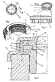
- an outer steering shaft 1 is attached to a bearing bushing 3 held on the end face of a stop collar 2 for axially moveable accommodation of an inner steering shaft (not shown).
- the bearing bush 3 consists of a hard first plastic - in the present embodiment made of polyamide - with a chemically embedded lubricant, for example Teflon or molybdenum dioxide.
- longitudinal ribs 4 with a semicircular cross section and / or transverse ribs 5 lying between these are formed at regular intervals.
- first toothed ribs 6 are formed on the end face of the stop collar 2 and the bearing bush 3.
- a sealing element 7 that overlaps the side face of the stop collar 2 is fastened in a form-fitting manner, with the aid of second toothed ribs 8 formed on the underside of the sealing element 7 and engaging in the spaces between the first toothed ribs 6.
- the sealing element 7 consists of a soft second plastic, that is, a thermoplastic elastomer (TPE, technical rubber), which shrinks when it cools on the bearing bush made of the hard plastic, so that its (second) toothed ribs 8 fit into the (first) Toothed ribs 6 of the bearing bush 3 claw and thus a firm, intimate - but not rubberized adhesive - connection between the bearing bush 3 and the sealing element 7 is established.
- TPE thermoplastic elastomer
- the pressure acting on the sealing element 7 made of soft thermoplastic elastomer is absorbed by the bearing bush 3 and the toothed ribs 6 made of hard polyamide.
- the reduced material proportion of thermoplastic elastomer due to the rib structure also provides direct support for the sealing element 7 and thus avoids its tendency to flow away at high pressure.
- the sealing element 7 has an inner leg 9 (lip sealing ring) with two sealing lips running around one another at a distance, that is, a first sealing lip 10 and a second sealing lip 11 with a lubricant reservoir 12 formed between them.
- a circumferential outer leg rests on the side surface of the stop collar 2 and, with its bulge 13 protruding slightly over the side surface of the stop collar 2 and resting on the end face of the outer steering shaft 1, forms as a whole a static sealing ring 14 with a large spring travel corresponding to the large leg length.
- This static seal retains its elastic sealing effect even at very high pressure.
- a groove 15 is formed in the sealing element 8 at the transition to this sealing lip 10.
- the bearing bush arrangement thus consists of only two easy-to-assemble components with five functions, that is, plain bearings, static sealing, dynamic sealing including lubricating effect and fastening.
- the manufacturing and assembly outlay for such a bearing bush arrangement is therefore low.
- a one-piece sealing element with excellent sealing properties against pressure or spray water, steam, dirt, dust and sand is provided.
- the two plastic components of the first component are positively connected to one another in such a way that the soft sealing material is prevented from flowing away under the action of pressure.
Landscapes
- Engineering & Computer Science (AREA)
- General Engineering & Computer Science (AREA)
- Mechanical Engineering (AREA)
- Chemical & Material Sciences (AREA)
- Combustion & Propulsion (AREA)
- Transportation (AREA)
- Sealing Of Bearings (AREA)
- Sliding-Contact Bearings (AREA)
- Sealing Devices (AREA)
- Steering Controls (AREA)
- Steering Devices For Bicycles And Motorcycles (AREA)
- Shafts, Cranks, Connecting Bars, And Related Bearings (AREA)
- Support Of The Bearing (AREA)
Claims (8)
- Système de coussinet pour un arbre de direction en deux parties pour la liaison axialement mobile et étanchéifiante d'un arbre de direction extérieur (1) avec un arbre de direction intérieur, qui comprend un coussinet (3), des moyens d'étanchéité statiques et dynamiques et un couvercle (16), caractérisé en ce que le coussinet (3) composé d'une matière plastique dure, doté d'un collet de butée (2) est relié en face avant par une denture rétractable (6, 8) interférant par conformité de forme à un élément d'étanchéité (7) composé de matière plastique élastique souple, à étanchéification statique et dynamique, constitué en une pièce et soutient à cet effet le matériau élastique souple, sachant que la denture rétractable est composée de premières et deuxièmes cannelures de denture (6, 8) constituées respectivement comme une structure de mirador sur l'élément d'étanchéité et sur le coussinet (3), qui sont mécaniquement accrochées l'une dans l'autre en raison d'un retrait se produisant au refroidissement de la matière plastique, sachant qu'une branche intérieure (9) périphérique de l'élément d'étanchéité (7) comporte une première lèvre d'étanchéité (10) prévue pour l'étanchéification dynamique et une branche extérieure périphérique de l'élément d'étanchéité (7) venant en prise sur la face latérale du collet de butée (2) est en contact en face avant avec l'arbre de direction extérieur (1) et se comporte comme une bague d'étanchéité statique (14).
- Système de coussinet selon la revendication 1, caractérisé en ce qu'à distance de la première lèvre d'étanchéité périphérique (10) est constituée une deuxième lèvre d'étanchéité périphérique (11), qui contient un réservoir de lubrifiant (12).
- Système de coussinet selon la revendication 1, caractérisé en ce qu'une rainure (15) périphérique est conformé dans l'élément d'étanchéité (7) à la transition avec la branche intérieure (9) formant les lèvres d'étanchéité.
- Système de coussinet selon la revendication 1, caractérisé en ce que la bague d'étanchéité statique (14) de l'élément d'étanchéité (7) comporte sur sa face avant libre un bombement (13) dépassant au-dessus de la surface latérale du collet de butée (2), en contact avec l'arbre de direction (1).
- Système de coussinet selon la revendication 1, caractérisé en ce que les nervures longitudinales (4) et/ou nervures transversales (5) semi-circulaires en section sont conformées sur la surface extérieure du coussinet (1).
- Système de coussinet selon la revendication 1, caractérisé en ce que la matière plastique utilisée pour le coussinet (3) est du polyamide avec un agent de glissement chimiquement incorporé.
- Système de coussinet selon la revendication 7, caractérisé en ce que l'agent de glissement est du Téflon ou du dioxyde de molybdène.
- Système de coussinet selon la revendication 1, caractérisé en ce que la matière plastique utilisée pour l'élément d'étanchéité (7) est un élastomère thermoplastique.
Applications Claiming Priority (2)
| Application Number | Priority Date | Filing Date | Title |
|---|---|---|---|
| DE102006012057A DE102006012057A1 (de) | 2006-03-08 | 2006-03-08 | Lagerbuchsensystem für eine zweiteilige Lenkwelle |
| PCT/DE2007/000203 WO2007101414A1 (fr) | 2006-03-08 | 2007-01-31 | Système de coussinet pour un arbre de direction en deux parties |
Publications (3)
| Publication Number | Publication Date |
|---|---|
| EP1994316A1 EP1994316A1 (fr) | 2008-11-26 |
| EP1994316B1 EP1994316B1 (fr) | 2010-02-24 |
| EP1994316B2 true EP1994316B2 (fr) | 2021-03-10 |
Family
ID=38017260
Family Applications (1)
| Application Number | Title | Priority Date | Filing Date |
|---|---|---|---|
| EP07721875.8A Not-in-force EP1994316B2 (fr) | 2006-03-08 | 2007-01-31 | Système de coussinet pour un arbre de direction en deux parties |
Country Status (5)
| Country | Link |
|---|---|
| US (1) | US7988362B2 (fr) |
| EP (1) | EP1994316B2 (fr) |
| AT (1) | ATE458943T1 (fr) |
| DE (2) | DE102006012057A1 (fr) |
| WO (1) | WO2007101414A1 (fr) |
Families Citing this family (15)
| Publication number | Priority date | Publication date | Assignee | Title |
|---|---|---|---|---|
| DE102009000432A1 (de) * | 2009-01-27 | 2010-07-29 | Zf Lenksysteme Gmbh | Teleskopierbare Lenkwelle |
| DE102010028297B4 (de) | 2010-04-28 | 2023-08-24 | Robert Bosch Gmbh | Lagerbuchsen-Anordnung für eine teleskopartige Lenkwelle und damit ausgestattetes Lenksystem |
| ITTO20110581A1 (it) * | 2011-07-01 | 2013-01-02 | Skf Ab | Complesso anulare di tenuta, in particolare per l'interposizione tra elementi soggetti a disassamento |
| ITTO20130460A1 (it) * | 2013-06-04 | 2014-12-05 | Skf Ab | Complesso di tenuta inseribile tra due organi relativamente scorrevoli |
| DE102013108421A1 (de) | 2013-08-05 | 2015-02-05 | Dr. Walter Hunger Beteiligungs GmbH & Co. Besitz KG | Abstreifereinheit sowie hydraulische Arbeitsvorrichtung mit einer Abstreifereinheit |
| CN204511431U (zh) * | 2014-01-03 | 2015-07-29 | 刘素华 | 采掘装载机密封浮动套浮动密封往复冲击装置 |
| DE102014209127A1 (de) * | 2014-05-14 | 2015-11-19 | Schaeffler Technologies AG & Co. KG | Dichtringträger für einen Radialwellendichtring |
| DE102014110077B4 (de) * | 2014-07-17 | 2016-02-18 | Dionex Softron Gmbh | Dichtungssystem und Verfahren zu seiner Montage |
| DE202014103932U1 (de) | 2014-08-21 | 2014-09-19 | Ford Global Technologies, Llc | Lagerbuchse sowie schwingungsdämpfende Verbindungsanordnung |
| DE102014216670B4 (de) | 2014-08-21 | 2016-05-19 | Ford Global Technologies, Llc | Lagerbuchse |
| DE102014216672A1 (de) | 2014-08-21 | 2016-02-25 | Ford Global Technologies, Llc | Lagerbuchse sowie schwingungsdämpfende Verbindungsanordnung |
| DE102015008987B4 (de) * | 2014-12-12 | 2016-08-11 | Carl Freudenberg Kg | Stoßdämpfer und dessen Verwendung |
| DE102016114678A1 (de) | 2016-08-08 | 2018-02-08 | Thyssenkrupp Ag | Drehlageranordnung für eine Lenksäule eines Kraftfahrzeugs |
| US11465670B2 (en) * | 2019-04-18 | 2022-10-11 | Zf Active Safety And Electronics Us Llc | Steering shaft support assembly |
| DE102020121886A1 (de) | 2020-08-20 | 2022-02-24 | Woco Industrietechnik Gmbh | KFZ-Lenksäulenlagerung |
Citations (5)
| Publication number | Priority date | Publication date | Assignee | Title |
|---|---|---|---|---|
| DE69101303T2 (de) † | 1990-11-28 | 1994-10-06 | Ecia Equip Composants Ind Auto | Elastisches Gleitlager und seine Verwendung für Automobillenkungen. |
| DE19615157A1 (de) † | 1996-04-17 | 1997-10-23 | Lucas Ind Plc | Ringförmiges Dichtelement |
| DE10010524A1 (de) † | 2000-03-07 | 2001-09-27 | Freudenberg Carl Fa | Abstreifer mit integrierter Dichtung |
| DE10329893A1 (de) † | 2003-07-03 | 2005-02-03 | Carl Freudenberg Kg | Dichtung |
| WO2006007822A1 (fr) † | 2004-07-20 | 2006-01-26 | Zf Friedrichshafen Ag | Ensemble palier |
Family Cites Families (22)
| Publication number | Priority date | Publication date | Assignee | Title |
|---|---|---|---|---|
| US2512098A (en) * | 1945-10-24 | 1950-06-20 | Gratzmuller Jean Louis | Sealing packing |
| FR1357192A (fr) * | 1963-03-26 | 1964-04-03 | Simmerwerke Simmer Kg | Joint d'étanchéité radial annulaire rapporté sur un coussinet par vulcanisation ou collage |
| DE6910130U (de) | 1969-03-10 | 1969-10-16 | Fendt & Co Xaver | Anhaengerkupplung |
| DE2948248A1 (de) * | 1979-11-30 | 1981-06-04 | Bertrams Ag, 5900 Siegen | Wandelement fuer laermschutzwaende |
| US4261583A (en) * | 1979-12-10 | 1981-04-14 | Vries Jr Donald S De | Unitary rod gland assembly |
| JPS58100884U (ja) * | 1981-12-28 | 1983-07-08 | 株式会社昭和製作所 | 二輪車等のフロントフオ−クのシ−ル装置 |
| DE3246349A1 (de) * | 1982-12-15 | 1984-06-20 | FAG Kugelfischer Georg Schäfer KGaA, 8720 Schweinfurt | Geberzylinder |
| DE3501334C1 (de) * | 1985-01-17 | 1986-04-10 | Fa. Carl Freudenberg, 6940 Weinheim | Dichtung |
| US4934668A (en) * | 1988-08-19 | 1990-06-19 | Chicago Rawhide Manufacturing Co. | Unitary seal for gas pressure spring assembly |
| US5421591A (en) * | 1990-02-26 | 1995-06-06 | Zahnradfabrik Friedrichshafen Ag | Sealing arrangement |
| JPH0914452A (ja) * | 1995-04-26 | 1997-01-14 | Nippon Seiko Kk | オイルシールリップの潤滑構造 |
| FR2741316B1 (fr) * | 1995-11-17 | 1998-01-02 | Nacam | Dispositif d'articulation d'une colonne de direction de vehicule automobile |
| US6203022B1 (en) * | 1996-04-17 | 2001-03-20 | Lucas Industries Public Limited | Annular sealing element |
| US6065292A (en) * | 1997-03-14 | 2000-05-23 | Lucas Industries Plc | Master cylinder |
| DE19839597A1 (de) * | 1998-08-31 | 2000-03-02 | Continental Teves Ag & Co Ohg | Dichtungseinsatz, insbesondere für einen Kolben einer hydraulischen Fahrzeugbremsanlage |
| DE19917006A1 (de) * | 1999-04-15 | 2000-10-19 | Mannesmann Sachs Ag | Zylinder für eine hydraulische Anlage |
| DE10108775B4 (de) * | 2001-02-23 | 2006-04-06 | Lucas Automotive Gmbh | Hauptzylinder |
| US6681885B2 (en) * | 2001-09-19 | 2004-01-27 | Trw Inc. | Rack and pinion steering gear with powdered metal bushing |
| JP2004237760A (ja) * | 2003-02-03 | 2004-08-26 | Advics:Kk | シール構造およびそのシール構造を用いた入力ロッド引張り式ブレーキ倍力装置 |
| US6896110B2 (en) * | 2003-09-25 | 2005-05-24 | Tenneco Automotive Operating Company Inc. | Temperature compensated dual acting slip |
| WO2005068277A1 (fr) * | 2004-01-15 | 2005-07-28 | Nsk Ltd. | Capuchon d'axe de direction |
| JP5078338B2 (ja) * | 2006-12-12 | 2012-11-21 | ルネサスエレクトロニクス株式会社 | 半導体記憶装置 |
-
2006
- 2006-03-08 DE DE102006012057A patent/DE102006012057A1/de not_active Withdrawn
-
2007
- 2007-01-31 US US12/224,702 patent/US7988362B2/en not_active Expired - Fee Related
- 2007-01-31 EP EP07721875.8A patent/EP1994316B2/fr not_active Not-in-force
- 2007-01-31 WO PCT/DE2007/000203 patent/WO2007101414A1/fr active Application Filing
- 2007-01-31 AT AT07721875T patent/ATE458943T1/de active
- 2007-01-31 DE DE502007002926T patent/DE502007002926D1/de active Active
Patent Citations (5)
| Publication number | Priority date | Publication date | Assignee | Title |
|---|---|---|---|---|
| DE69101303T2 (de) † | 1990-11-28 | 1994-10-06 | Ecia Equip Composants Ind Auto | Elastisches Gleitlager und seine Verwendung für Automobillenkungen. |
| DE19615157A1 (de) † | 1996-04-17 | 1997-10-23 | Lucas Ind Plc | Ringförmiges Dichtelement |
| DE10010524A1 (de) † | 2000-03-07 | 2001-09-27 | Freudenberg Carl Fa | Abstreifer mit integrierter Dichtung |
| DE10329893A1 (de) † | 2003-07-03 | 2005-02-03 | Carl Freudenberg Kg | Dichtung |
| WO2006007822A1 (fr) † | 2004-07-20 | 2006-01-26 | Zf Friedrichshafen Ag | Ensemble palier |
Also Published As
| Publication number | Publication date |
|---|---|
| US7988362B2 (en) | 2011-08-02 |
| DE102006012057A1 (de) | 2007-09-13 |
| DE502007002926D1 (de) | 2010-04-08 |
| US20090028479A1 (en) | 2009-01-29 |
| WO2007101414A1 (fr) | 2007-09-13 |
| EP1994316A1 (fr) | 2008-11-26 |
| ATE458943T1 (de) | 2010-03-15 |
| EP1994316B1 (fr) | 2010-02-24 |
Similar Documents
| Publication | Publication Date | Title |
|---|---|---|
| EP1994316B2 (fr) | Système de coussinet pour un arbre de direction en deux parties | |
| DE4037966C2 (de) | Elastisches Gleitlager für Fahrwerksteile | |
| DE4036051C1 (fr) | ||
| EP0485696B1 (fr) | Palier élastique | |
| DE102010028297B4 (de) | Lagerbuchsen-Anordnung für eine teleskopartige Lenkwelle und damit ausgestattetes Lenksystem | |
| EP1769168B1 (fr) | Ensemble palier | |
| WO2008068179A2 (fr) | Palier de jambe de suspension | |
| DE102014206658B4 (de) | Federbeinlager mit einer Zweikomponenten Kappe | |
| EP1612066A1 (fr) | Rondelle pour un palier à contact lisse | |
| DE4120772C2 (de) | Radial und axial belastbares Drehgleitlager für Fahrwerksteile in Kraftfahrzeugen | |
| DE2542085C2 (de) | Dichtanordnung | |
| EP1132642B1 (fr) | Support en gomme | |
| DE102015209776A1 (de) | Federbeinlager | |
| DE102010035188A1 (de) | Federbeingleitlager | |
| WO2007085323A2 (fr) | Partie de tête d'une suspension à jambe de suspension et suspension à jambe de suspension | |
| DE102004031559B4 (de) | Elastomeres Buchsenlager mit verbessertem Torsionsverhalten | |
| DE19834678C2 (de) | Abgedichtetes, Schwenkbewegungen ausführendes Gelenklager | |
| DE1111957B (de) | Aus elastischem Werkstoff bestehende Lagerung zur Aufnahme von in radialer Richtung auftretenden Kraeften, vorzugsweise Lagerung fuer Torsionsfederstaebe an Kraftfahrzeugen | |
| DE102014219858B4 (de) | Kreuzgelenk | |
| DE102022207218A1 (de) | Aufhängungslagereinheit mit Versteifungseinsatz | |
| DE102015209335A1 (de) | Federbeinstützlageranordnung sowie Federbein einer Radaufhängung eines Kraftfahrzeuges | |
| DE102016208720A1 (de) | Federbeinlager | |
| DE8235995U1 (de) | Federnder Träger für einen Stoßdämpfer einer vorderen Federung eines Fahrzeugs | |
| DE102008028914A1 (de) | Scheibenbremse für ein Nutzfahrzeug | |
| DE3437247A1 (de) | Dichtung, insbesondere fuer laufwerksketten |
Legal Events
| Date | Code | Title | Description |
|---|---|---|---|
| PUAI | Public reference made under article 153(3) epc to a published international application that has entered the european phase |
Free format text: ORIGINAL CODE: 0009012 |
|
| 17P | Request for examination filed |
Effective date: 20081001 |
|
| AK | Designated contracting states |
Kind code of ref document: A1 Designated state(s): AT BE BG CH CY CZ DE DK EE ES FI FR GB GR HU IE IS IT LI LT LU LV MC NL PL PT RO SE SI SK TR |
|
| GRAP | Despatch of communication of intention to grant a patent |
Free format text: ORIGINAL CODE: EPIDOSNIGR1 |
|
| GRAS | Grant fee paid |
Free format text: ORIGINAL CODE: EPIDOSNIGR3 |
|
| GRAA | (expected) grant |
Free format text: ORIGINAL CODE: 0009210 |
|
| STAA | Information on the status of an ep patent application or granted ep patent |
Free format text: STATUS: THE PATENT HAS BEEN GRANTED |
|
| AK | Designated contracting states |
Kind code of ref document: B1 Designated state(s): AT BE BG CH CY CZ DE DK EE ES FI FR GB GR HU IE IS IT LI LT LU LV MC NL PL PT RO SE SI SK TR |
|
| REG | Reference to a national code |
Ref country code: GB Ref legal event code: FG4D Free format text: NOT ENGLISH |
|
| REG | Reference to a national code |
Ref country code: CH Ref legal event code: EP |
|
| REG | Reference to a national code |
Ref country code: IE Ref legal event code: FG4D Free format text: LANGUAGE OF EP DOCUMENT: GERMAN |
|
| REF | Corresponds to: |
Ref document number: 502007002926 Country of ref document: DE Date of ref document: 20100408 Kind code of ref document: P |
|
| REG | Reference to a national code |
Ref country code: NL Ref legal event code: VDEP Effective date: 20100224 |
|
| LTIE | Lt: invalidation of european patent or patent extension |
Effective date: 20100224 |
|
| PG25 | Lapsed in a contracting state [announced via postgrant information from national office to epo] |
Ref country code: PT Free format text: LAPSE BECAUSE OF FAILURE TO SUBMIT A TRANSLATION OF THE DESCRIPTION OR TO PAY THE FEE WITHIN THE PRESCRIBED TIME-LIMIT Effective date: 20100625 Ref country code: IS Free format text: LAPSE BECAUSE OF FAILURE TO SUBMIT A TRANSLATION OF THE DESCRIPTION OR TO PAY THE FEE WITHIN THE PRESCRIBED TIME-LIMIT Effective date: 20100624 Ref country code: LT Free format text: LAPSE BECAUSE OF FAILURE TO SUBMIT A TRANSLATION OF THE DESCRIPTION OR TO PAY THE FEE WITHIN THE PRESCRIBED TIME-LIMIT Effective date: 20100224 |
|
| PG25 | Lapsed in a contracting state [announced via postgrant information from national office to epo] |
Ref country code: PL Free format text: LAPSE BECAUSE OF FAILURE TO SUBMIT A TRANSLATION OF THE DESCRIPTION OR TO PAY THE FEE WITHIN THE PRESCRIBED TIME-LIMIT Effective date: 20100224 Ref country code: FI Free format text: LAPSE BECAUSE OF FAILURE TO SUBMIT A TRANSLATION OF THE DESCRIPTION OR TO PAY THE FEE WITHIN THE PRESCRIBED TIME-LIMIT Effective date: 20100224 Ref country code: SI Free format text: LAPSE BECAUSE OF FAILURE TO SUBMIT A TRANSLATION OF THE DESCRIPTION OR TO PAY THE FEE WITHIN THE PRESCRIBED TIME-LIMIT Effective date: 20100224 Ref country code: LV Free format text: LAPSE BECAUSE OF FAILURE TO SUBMIT A TRANSLATION OF THE DESCRIPTION OR TO PAY THE FEE WITHIN THE PRESCRIBED TIME-LIMIT Effective date: 20100224 |
|
| REG | Reference to a national code |
Ref country code: IE Ref legal event code: FD4D |
|
| PG25 | Lapsed in a contracting state [announced via postgrant information from national office to epo] |
Ref country code: CY Free format text: LAPSE BECAUSE OF FAILURE TO SUBMIT A TRANSLATION OF THE DESCRIPTION OR TO PAY THE FEE WITHIN THE PRESCRIBED TIME-LIMIT Effective date: 20100224 Ref country code: RO Free format text: LAPSE BECAUSE OF FAILURE TO SUBMIT A TRANSLATION OF THE DESCRIPTION OR TO PAY THE FEE WITHIN THE PRESCRIBED TIME-LIMIT Effective date: 20100224 Ref country code: IE Free format text: LAPSE BECAUSE OF FAILURE TO SUBMIT A TRANSLATION OF THE DESCRIPTION OR TO PAY THE FEE WITHIN THE PRESCRIBED TIME-LIMIT Effective date: 20100224 Ref country code: SE Free format text: LAPSE BECAUSE OF FAILURE TO SUBMIT A TRANSLATION OF THE DESCRIPTION OR TO PAY THE FEE WITHIN THE PRESCRIBED TIME-LIMIT Effective date: 20100224 Ref country code: EE Free format text: LAPSE BECAUSE OF FAILURE TO SUBMIT A TRANSLATION OF THE DESCRIPTION OR TO PAY THE FEE WITHIN THE PRESCRIBED TIME-LIMIT Effective date: 20100224 Ref country code: ES Free format text: LAPSE BECAUSE OF FAILURE TO SUBMIT A TRANSLATION OF THE DESCRIPTION OR TO PAY THE FEE WITHIN THE PRESCRIBED TIME-LIMIT Effective date: 20100604 Ref country code: GR Free format text: LAPSE BECAUSE OF FAILURE TO SUBMIT A TRANSLATION OF THE DESCRIPTION OR TO PAY THE FEE WITHIN THE PRESCRIBED TIME-LIMIT Effective date: 20100525 Ref country code: NL Free format text: LAPSE BECAUSE OF FAILURE TO SUBMIT A TRANSLATION OF THE DESCRIPTION OR TO PAY THE FEE WITHIN THE PRESCRIBED TIME-LIMIT Effective date: 20100224 |
|
| PLBI | Opposition filed |
Free format text: ORIGINAL CODE: 0009260 |
|
| PG25 | Lapsed in a contracting state [announced via postgrant information from national office to epo] |
Ref country code: BG Free format text: LAPSE BECAUSE OF FAILURE TO SUBMIT A TRANSLATION OF THE DESCRIPTION OR TO PAY THE FEE WITHIN THE PRESCRIBED TIME-LIMIT Effective date: 20100524 Ref country code: SK Free format text: LAPSE BECAUSE OF FAILURE TO SUBMIT A TRANSLATION OF THE DESCRIPTION OR TO PAY THE FEE WITHIN THE PRESCRIBED TIME-LIMIT Effective date: 20100224 Ref country code: CZ Free format text: LAPSE BECAUSE OF FAILURE TO SUBMIT A TRANSLATION OF THE DESCRIPTION OR TO PAY THE FEE WITHIN THE PRESCRIBED TIME-LIMIT Effective date: 20100224 |
|
| 26 | Opposition filed |
Opponent name: ZF LENKSYSTEME GMBH Effective date: 20101124 |
|
| PLAX | Notice of opposition and request to file observation + time limit sent |
Free format text: ORIGINAL CODE: EPIDOSNOBS2 |
|
| PG25 | Lapsed in a contracting state [announced via postgrant information from national office to epo] |
Ref country code: DK Free format text: LAPSE BECAUSE OF FAILURE TO SUBMIT A TRANSLATION OF THE DESCRIPTION OR TO PAY THE FEE WITHIN THE PRESCRIBED TIME-LIMIT Effective date: 20100224 |
|
| PLBB | Reply of patent proprietor to notice(s) of opposition received |
Free format text: ORIGINAL CODE: EPIDOSNOBS3 |
|
| BERE | Be: lapsed |
Owner name: DITTMANN, LUDWIG Effective date: 20110131 |
|
| PG25 | Lapsed in a contracting state [announced via postgrant information from national office to epo] |
Ref country code: MC Free format text: LAPSE BECAUSE OF NON-PAYMENT OF DUE FEES Effective date: 20110131 |
|
| REG | Reference to a national code |
Ref country code: CH Ref legal event code: PL |
|
| PG25 | Lapsed in a contracting state [announced via postgrant information from national office to epo] |
Ref country code: LI Free format text: LAPSE BECAUSE OF NON-PAYMENT OF DUE FEES Effective date: 20110131 Ref country code: CH Free format text: LAPSE BECAUSE OF NON-PAYMENT OF DUE FEES Effective date: 20110131 |
|
| PG25 | Lapsed in a contracting state [announced via postgrant information from national office to epo] |
Ref country code: BE Free format text: LAPSE BECAUSE OF NON-PAYMENT OF DUE FEES Effective date: 20110131 |
|
| REG | Reference to a national code |
Ref country code: AT Ref legal event code: MM01 Ref document number: 458943 Country of ref document: AT Kind code of ref document: T Effective date: 20120131 |
|
| PG25 | Lapsed in a contracting state [announced via postgrant information from national office to epo] |
Ref country code: LU Free format text: LAPSE BECAUSE OF NON-PAYMENT OF DUE FEES Effective date: 20110131 |
|
| PG25 | Lapsed in a contracting state [announced via postgrant information from national office to epo] |
Ref country code: AT Free format text: LAPSE BECAUSE OF NON-PAYMENT OF DUE FEES Effective date: 20120131 |
|
| PG25 | Lapsed in a contracting state [announced via postgrant information from national office to epo] |
Ref country code: TR Free format text: LAPSE BECAUSE OF FAILURE TO SUBMIT A TRANSLATION OF THE DESCRIPTION OR TO PAY THE FEE WITHIN THE PRESCRIBED TIME-LIMIT Effective date: 20100224 |
|
| PG25 | Lapsed in a contracting state [announced via postgrant information from national office to epo] |
Ref country code: HU Free format text: LAPSE BECAUSE OF FAILURE TO SUBMIT A TRANSLATION OF THE DESCRIPTION OR TO PAY THE FEE WITHIN THE PRESCRIBED TIME-LIMIT Effective date: 20100224 |
|
| RDAF | Communication despatched that patent is revoked |
Free format text: ORIGINAL CODE: EPIDOSNREV1 |
|
| APBM | Appeal reference recorded |
Free format text: ORIGINAL CODE: EPIDOSNREFNO |
|
| APBP | Date of receipt of notice of appeal recorded |
Free format text: ORIGINAL CODE: EPIDOSNNOA2O |
|
| APAH | Appeal reference modified |
Free format text: ORIGINAL CODE: EPIDOSCREFNO |
|
| APBQ | Date of receipt of statement of grounds of appeal recorded |
Free format text: ORIGINAL CODE: EPIDOSNNOA3O |
|
| PGFP | Annual fee paid to national office [announced via postgrant information from national office to epo] |
Ref country code: GB Payment date: 20140123 Year of fee payment: 8 |
|
| PLAB | Opposition data, opponent's data or that of the opponent's representative modified |
Free format text: ORIGINAL CODE: 0009299OPPO |
|
| R26 | Opposition filed (corrected) |
Opponent name: ROBERT BOSCH AUTOMOTIVE STEERING GMBH Effective date: 20101124 |
|
| GBPC | Gb: european patent ceased through non-payment of renewal fee |
Effective date: 20150131 |
|
| PG25 | Lapsed in a contracting state [announced via postgrant information from national office to epo] |
Ref country code: GB Free format text: LAPSE BECAUSE OF NON-PAYMENT OF DUE FEES Effective date: 20150131 |
|
| REG | Reference to a national code |
Ref country code: FR Ref legal event code: PLFP Year of fee payment: 10 |
|
| REG | Reference to a national code |
Ref country code: FR Ref legal event code: PLFP Year of fee payment: 11 |
|
| APBU | Appeal procedure closed |
Free format text: ORIGINAL CODE: EPIDOSNNOA9O |
|
| REG | Reference to a national code |
Ref country code: FR Ref legal event code: PLFP Year of fee payment: 12 |
|
| PGFP | Annual fee paid to national office [announced via postgrant information from national office to epo] |
Ref country code: FR Payment date: 20180124 Year of fee payment: 12 |
|
| REG | Reference to a national code |
Ref country code: DE Ref legal event code: R082 Ref document number: 502007002926 Country of ref document: DE Representative=s name: ADARES PATENT- UND RECHTSANWAELTE REININGER & , DE |
|
| APAH | Appeal reference modified |
Free format text: ORIGINAL CODE: EPIDOSCREFNO |
|
| APBM | Appeal reference recorded |
Free format text: ORIGINAL CODE: EPIDOSNREFNO |
|
| APBP | Date of receipt of notice of appeal recorded |
Free format text: ORIGINAL CODE: EPIDOSNNOA2O |
|
| PG25 | Lapsed in a contracting state [announced via postgrant information from national office to epo] |
Ref country code: FR Free format text: LAPSE BECAUSE OF NON-PAYMENT OF DUE FEES Effective date: 20190131 |
|
| APBU | Appeal procedure closed |
Free format text: ORIGINAL CODE: EPIDOSNNOA9O |
|
| PUAH | Patent maintained in amended form |
Free format text: ORIGINAL CODE: 0009272 |
|
| STAA | Information on the status of an ep patent application or granted ep patent |
Free format text: STATUS: PATENT MAINTAINED AS AMENDED |
|
| 27A | Patent maintained in amended form |
Effective date: 20210310 |
|
| AK | Designated contracting states |
Kind code of ref document: B2 Designated state(s): AT BE BG CH CY CZ DE DK EE ES FI FR GB GR HU IE IS IT LI LT LU LV MC NL PL PT RO SE SI SK TR |
|
| REG | Reference to a national code |
Ref country code: DE Ref legal event code: R102 Ref document number: 502007002926 Country of ref document: DE |
|
| PGFP | Annual fee paid to national office [announced via postgrant information from national office to epo] |
Ref country code: IT Payment date: 20210129 Year of fee payment: 15 |
|
| PGFP | Annual fee paid to national office [announced via postgrant information from national office to epo] |
Ref country code: DE Payment date: 20210113 Year of fee payment: 15 |
|
| REG | Reference to a national code |
Ref country code: DE Ref legal event code: R119 Ref document number: 502007002926 Country of ref document: DE |
|
| PG25 | Lapsed in a contracting state [announced via postgrant information from national office to epo] |
Ref country code: DE Free format text: LAPSE BECAUSE OF NON-PAYMENT OF DUE FEES Effective date: 20220802 |
|
| PG25 | Lapsed in a contracting state [announced via postgrant information from national office to epo] |
Ref country code: IT Free format text: LAPSE BECAUSE OF NON-PAYMENT OF DUE FEES Effective date: 20220131 |