EP1992846B1 - Oil pump system for vehicle - Google Patents
Oil pump system for vehicle Download PDFInfo
- Publication number
- EP1992846B1 EP1992846B1 EP08009151A EP08009151A EP1992846B1 EP 1992846 B1 EP1992846 B1 EP 1992846B1 EP 08009151 A EP08009151 A EP 08009151A EP 08009151 A EP08009151 A EP 08009151A EP 1992846 B1 EP1992846 B1 EP 1992846B1
- Authority
- EP
- European Patent Office
- Prior art keywords
- pump
- oil pump
- hydraulic fluid
- electric power
- vane
- Prior art date
- Legal status (The legal status is an assumption and is not a legal conclusion. Google has not performed a legal analysis and makes no representation as to the accuracy of the status listed.)
- Active
Links
Images


Classifications
-
- F—MECHANICAL ENGINEERING; LIGHTING; HEATING; WEAPONS; BLASTING
- F04—POSITIVE - DISPLACEMENT MACHINES FOR LIQUIDS; PUMPS FOR LIQUIDS OR ELASTIC FLUIDS
- F04C—ROTARY-PISTON, OR OSCILLATING-PISTON, POSITIVE-DISPLACEMENT MACHINES FOR LIQUIDS; ROTARY-PISTON, OR OSCILLATING-PISTON, POSITIVE-DISPLACEMENT PUMPS
- F04C14/00—Control of, monitoring of, or safety arrangements for, machines, pumps or pumping installations
- F04C14/06—Control of, monitoring of, or safety arrangements for, machines, pumps or pumping installations specially adapted for stopping, starting, idling or no-load operation
-
- F—MECHANICAL ENGINEERING; LIGHTING; HEATING; WEAPONS; BLASTING
- F04—POSITIVE - DISPLACEMENT MACHINES FOR LIQUIDS; PUMPS FOR LIQUIDS OR ELASTIC FLUIDS
- F04C—ROTARY-PISTON, OR OSCILLATING-PISTON, POSITIVE-DISPLACEMENT MACHINES FOR LIQUIDS; ROTARY-PISTON, OR OSCILLATING-PISTON, POSITIVE-DISPLACEMENT PUMPS
- F04C14/00—Control of, monitoring of, or safety arrangements for, machines, pumps or pumping installations
- F04C14/02—Control of, monitoring of, or safety arrangements for, machines, pumps or pumping installations specially adapted for several machines or pumps connected in series or in parallel
-
- F—MECHANICAL ENGINEERING; LIGHTING; HEATING; WEAPONS; BLASTING
- F04—POSITIVE - DISPLACEMENT MACHINES FOR LIQUIDS; PUMPS FOR LIQUIDS OR ELASTIC FLUIDS
- F04C—ROTARY-PISTON, OR OSCILLATING-PISTON, POSITIVE-DISPLACEMENT MACHINES FOR LIQUIDS; ROTARY-PISTON, OR OSCILLATING-PISTON, POSITIVE-DISPLACEMENT PUMPS
- F04C2/00—Rotary-piston machines or pumps
- F04C2/08—Rotary-piston machines or pumps of intermeshing-engagement type, i.e. with engagement of co-operating members similar to that of toothed gearing
- F04C2/10—Rotary-piston machines or pumps of intermeshing-engagement type, i.e. with engagement of co-operating members similar to that of toothed gearing of internal-axis type with the outer member having more teeth or tooth-equivalents, e.g. rollers, than the inner member
- F04C2/102—Rotary-piston machines or pumps of intermeshing-engagement type, i.e. with engagement of co-operating members similar to that of toothed gearing of internal-axis type with the outer member having more teeth or tooth-equivalents, e.g. rollers, than the inner member the two members rotating simultaneously around their respective axes
-
- F—MECHANICAL ENGINEERING; LIGHTING; HEATING; WEAPONS; BLASTING
- F04—POSITIVE - DISPLACEMENT MACHINES FOR LIQUIDS; PUMPS FOR LIQUIDS OR ELASTIC FLUIDS
- F04C—ROTARY-PISTON, OR OSCILLATING-PISTON, POSITIVE-DISPLACEMENT MACHINES FOR LIQUIDS; ROTARY-PISTON, OR OSCILLATING-PISTON, POSITIVE-DISPLACEMENT PUMPS
- F04C2/00—Rotary-piston machines or pumps
- F04C2/30—Rotary-piston machines or pumps having the characteristics covered by two or more groups F04C2/02, F04C2/08, F04C2/22, F04C2/24 or having the characteristics covered by one of these groups together with some other type of movement between co-operating members
- F04C2/34—Rotary-piston machines or pumps having the characteristics covered by two or more groups F04C2/02, F04C2/08, F04C2/22, F04C2/24 or having the characteristics covered by one of these groups together with some other type of movement between co-operating members having the movement defined in groups F04C2/08 or F04C2/22 and relative reciprocation between the co-operating members
- F04C2/344—Rotary-piston machines or pumps having the characteristics covered by two or more groups F04C2/02, F04C2/08, F04C2/22, F04C2/24 or having the characteristics covered by one of these groups together with some other type of movement between co-operating members having the movement defined in groups F04C2/08 or F04C2/22 and relative reciprocation between the co-operating members with vanes reciprocating with respect to the inner member
- F04C2/3446—Rotary-piston machines or pumps having the characteristics covered by two or more groups F04C2/02, F04C2/08, F04C2/22, F04C2/24 or having the characteristics covered by one of these groups together with some other type of movement between co-operating members having the movement defined in groups F04C2/08 or F04C2/22 and relative reciprocation between the co-operating members with vanes reciprocating with respect to the inner member the inner and outer member being in contact along more than one line or surface
-
- F—MECHANICAL ENGINEERING; LIGHTING; HEATING; WEAPONS; BLASTING
- F16—ENGINEERING ELEMENTS AND UNITS; GENERAL MEASURES FOR PRODUCING AND MAINTAINING EFFECTIVE FUNCTIONING OF MACHINES OR INSTALLATIONS; THERMAL INSULATION IN GENERAL
- F16H—GEARING
- F16H61/00—Control functions within control units of change-speed- or reversing-gearings for conveying rotary motion ; Control of exclusively fluid gearing, friction gearing, gearings with endless flexible members or other particular types of gearing
- F16H61/0021—Generation or control of line pressure
- F16H61/0025—Supply of control fluid; Pumps therefore
- F16H61/0031—Supply of control fluid; Pumps therefore using auxiliary pumps, e.g. pump driven by a different power source than the engine
-
- F—MECHANICAL ENGINEERING; LIGHTING; HEATING; WEAPONS; BLASTING
- F04—POSITIVE - DISPLACEMENT MACHINES FOR LIQUIDS; PUMPS FOR LIQUIDS OR ELASTIC FLUIDS
- F04C—ROTARY-PISTON, OR OSCILLATING-PISTON, POSITIVE-DISPLACEMENT MACHINES FOR LIQUIDS; ROTARY-PISTON, OR OSCILLATING-PISTON, POSITIVE-DISPLACEMENT PUMPS
- F04C2240/00—Components
- F04C2240/45—Hybrid prime mover
-
- F—MECHANICAL ENGINEERING; LIGHTING; HEATING; WEAPONS; BLASTING
- F16—ENGINEERING ELEMENTS AND UNITS; GENERAL MEASURES FOR PRODUCING AND MAINTAINING EFFECTIVE FUNCTIONING OF MACHINES OR INSTALLATIONS; THERMAL INSULATION IN GENERAL
- F16H—GEARING
- F16H2312/00—Driving activities
- F16H2312/14—Going to, or coming from standby operation, e.g. for engine start-stop operation at traffic lights
Definitions
- the present invention relates to an oil pump system for a vehicle according to the preamble of claim 1.
- a vehicle such as an automobile is provided with an oil pump system for a vehicle which includes a hydraulic pump for supplying a hydraulic fluid to a hydraulic actuator of an automatic transmission or the like provided in a vehicle such as an automobile so as to serve as a generating source of hydraulic pressure required for the hydraulic actuator, as well as a controller for controlling the operation of the hydraulic pump.
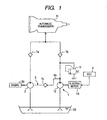
- the oil pump system for a vehicle is comprised of a hydraulic pump 5 which is driven by the torque of a rotating shaft (crankshaft) of an engine 50 and is adapted to supply to an automatic transmission 51 a hydraulic fluid for its speed ratio control through a piping with a check valve 7b provided therein.
- This system is further comprised of an electric power-driven oil pump (electric power-driven assist pump) 10 which is made up of a pump 12 and an electric motor 13 for driving the pump 12, so as to assist the hydraulic pressure of the hydraulic fluid during an idling stop of the automobile through a piping with a check valve 7b provided therein on the basis of a command from an engine control unit (ECU) 4 serving as the controller.
- This oil pump system for a vehicle is further comprised of a relief valve 7r disposed between a discharge portion of the pump 12 and the check valve 7b and adapted to relieve the hydraulic fluid into a drain when the discharge pressure of the electric power-driven oil pump 10 has assumed an overpressure state.
- Each of the hydraulic pump 5 and the electric power-driven oil pump 10 is adapted to suck the hydraulic fluid stored in an oil pan 52 provided below the engine 50 and supply (force feed) it to the automatic transmission 51.
- a so-called vane pump which is a kind of rotary volumetric pump, is frequently used since although it has a compact and simple structure, it has excellent characteristics of large capacity, low noise, and low pulsation (refer to JP-A-2000-18377 ).
- the aforementioned vane pump although not shown, includes a rotor, a plurality of vanes projecting retractably from a plurality of vane accommodating grooves provided in the rotor, and an elliptical cam ring surrounding the rotor. Further, as the rotor is rotated inside the cam ring, the vanes are adapted to project by the action of the centrifugal force due to the rotation of the rotor and by the hydraulic pressure on the discharge side of the vane pump so as to slide on a cam surface at the inner surface of the cam ring.
- a plurality of pump. chambers which are partitioned by the vanes and accommodate the hydraulic fluid, are formed between an outer periphery of the rotor and the cam surface. Among the pump chambers, those whose volume is large become high-pressure portions where the hydraulic fluid is set under high pressure, while those whose volume is small become low-pressure portions where the hydraulic fluid is set under low pressure.
- the hydraulic fluid is sucked from the oil pan 52 by the low-pressure portions, and the sucked hydraulic fluid is fed with pressure to the automatic transmission 51 by the high-pressure portions.
- the number of revolution of the electric motor 13 is controlled by the ECU 4, such that a total discharge rate, which is a total of a discharge rate of the vane pump and a discharge rate (auxiliary flow rate) of the electric power-driven oil pump 10, becomes a fixed rate irrespective of an engine speed (rotational speed of a rotating shaft of the engine 50).
- the discharge rate Qb' of the conventional vane pump exhibits a downwardly convex curve in the engine rotation range, and a power loss (corresponding to the area of So in Fig. 5 ) conventionally occurred.
- this power loss constitutes a hindrance to the smooth starting of the automobile. This also leads to a decline in the reliability of the vane pump as the hydraulic pump 5 for an automobile.
- the invention has been devised to overcome the above-described problems, and its object is to provide an oil pump system for a vehicle which allows the vehicle to be started smoothly when the engine is started from an idling stop state, without making a large structural change from a conventional oil pump system for a vehicle.
- an oil pump system for a vehicle comprising the features of claim 1.
- the check valve which opens when the hydraulic pressure of the hydraulic fluid delivered from the electric power-driven oil pump exceeds the hydraulic pressure of the hydraulic fluid in the vane accommodating grooves, is interposed in the communication oil passage allowing the discharge portion of the electric power-driven oil pump and the.vane accommodating grooves in the vane pump to communicate with each other.
- the check valve is closed by a simple configuration when the hydraulic pressure of the hydraulic fluid in the vane accommodating grooves exceeds the hydraulic pressure of the hydraulic fluid delivered from the electric power-driven oil pump. This avoids the trouble that, for example, a hindrance is caused to the rotation of the rotor, in a case where the vane accommodating grooves have assumed an overpressure state, and the pressing force with which the vanes press the cam surface has become excessively large.
- the hydraulic fluid is fed with pressure to the vane accommodating grooves accommodating the vanes in the vane pump, which serves as the hydraulic pump, by the operation of the electric power-driven oil pump assisting the hydraulic pressure of the transmission during the idling stop, so that the vanes are projected and are pressed against the cam surface.
- the start of the vane pump the low-pressure portions and the high-pressure portions are formed in the pump chambers between the outer periphery of the rotor and the cam surface, so that the hydraulic fluid is fed with pressure to the transmission.
- the electric power-driven oil pump has an internal gear pump and an electric motor for rotationally driving the pump and the number of revolution of the electric motor is controlled by the controller.
- the electric power-driven oil pump consists of the internal gear pump and the electric motor for rotational driving the pump, it is possible to realize an oil pump system for a vehicle which excels in the constant flow rate characteristic and in which the pulsation is small, with the result that the noise during operation is small.
- the oil pump system for a vehicle in accordance with the invention, it becomes possible to smoothly start the vehicle when the engine is started from an idling stop state, without making a large structural change from a conventional oil pump system for a vehicle.
- the oil pump system for a vehicle in accordance with this embodiment is provided in an automobile.having an automatic transmission.
- the oil pump system for a vehicle is comprised of a vane pump (hydraulic pump) 2 which is driven by the torque of a rotating shaft (crankshaft) (not shown) of an engine 50 and is adapted to supply to an automatic transmission 51 a hydraulic fluid for its operation (control) through a piping with a check valve 7a provided therein; and an electric power-driven oil pump (electric power-driven assist pump) 1 which is made up of an internal gear pump (pump) 12 and an electric motor 13 for driving the internal gear pump 12, so as to assist the hydraulic pressure of the hydraulic fluid during an idling stop of the automobile through a piping with a check valve 7b provided therein on the basis of a command from anECU 4 serving as a controller.
- a vane pump hydraulic pump
- electric power-driven assist pump electric power-driven assist pump
- This oil pump system for a vehicle is further comprised of a relief valve 7r disposed between a discharge portion of the internal gear pump 12 and the check valve 7b and adapted to relieve the hydraulic fluid into a drain when the discharge pressure of the electric power-driven oil pump 1 has assumed an overpressure state.
- Each of the hydraulic pump 2 and the electric power-driven oil pump 1 is adapted to suck the hydraulic fluid stored in an oil pan 52 provided below the engine 50 and supply (force feed) it to the automatic transmission 51.
- a check valve 7c which opens when the hydraulic pressure of the hydraulic fluid delivered from the electric power-driven oil pump 1 exceeds the hydraulic pressure of the hydraulic fluid in the aforementioned vane accommodating grooves, is interposed in the communication oil passage 6.
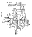
- the aforementioned vane pump includes a disk-shaped rotor 21; a plurality of vanes 23 respectively projecting retractably from a plurality of vane accommodating grooves 22 provided recessedly in the rotor 21 so as to extend radially from its inner side toward its outer periphery at substantially equal angular intervals; an elliptical cam ring 24 surrounding the rotor; a housing 26 for accommodating in its inner space 26a the cam ring 24 together with a disk-shaped pressure plate 25 in contact with one side surface thereof; and an end plate 27 which is joined to the housing 26 to close the inner space 26a and sandwich the cam ring 24 from its both side surface in cooperation with the housing 26.
- the rotor 21 is spline connected to a rotor shaft 28 which is passed through an axial portion of the pressure plate 25 and projects into the inner space 26a.
- a pivotal hole 28a which coaxially communicates with the inner space 26a, is penetratingly formed in the housing 26.
- the rotor shaft 28 has one end portion on a pivotal position side of the rotor 21 rotatably supported by a bearing bush 28b fixed to an axial position of the end plate 27 and by a rolling bearing 28c fitted in the pivotal hole 28a, and has its other end portion extended appropriately to an outer side of the pivotal hole 28a.
- the rotor shaft 28 is operatively connected to a driving source (not shown) of the engine 50 by means of a pulley 30 fitted to this extended end portion.
- the rotor 21 spline connected to the rotor shaft 28 is adapted to rotate on the inner side of the cam ring 24 by the driving force transmitted from the driving source.
- An annular hollow portion 27r which communicates with respective axial end portions 22b of cylindrical spaces 22a provided in radially inner end portions of the vane accommodating grooves 22 and extending in an axial direction, is provided in a joint surface 27s of the end plate 27 with respect to the cam ring 24. Further, a communication port 27p, which communicates with the annular hollow portion 27r and extends outwardly from a portion thereof to communicate with an external oil passage and the like, is penetratingly formed in the end plate 27.
- a plurality of pump chambers 24c which are partitioned by the vanes 23 and accommodate the hydraulic fluid, are formed between an outer periphery of the rotor 21 and the cam surface 24s.
- the aforementioned communication oil passage 6 is formed as an oil passage 6a on the discharge side of the electric power-driven pump 1 as well as the annular hollow portion 27r and the communication port 27p both formed in the end plate 27 are communicated with each other.
- the vanes 23 accommodated in the respective vane accommodating grooves 22 are projected radially outward by the pressure oil in the vane accommodating grooves 22, and are pressed against the cam surface 24s at the inner surface of the cam ring 24.
- the check valve 7c (see Fig. 1 ) interposed in the communication oil passage 6 closes when the hydraulic pressure of the hydraulic fluid in the vane accommodating grooves 22 exceeds the hydraulic pressure of the hydraulic fluid delivered from the electric power-driven oil pump 1. This avoids the trouble that, in a case where the vane accommodating grooves 22 is in an overpressure state, the pressing force with which the vanes 23 press the cam surface 24s becomes excessively large, causing a hindrance to the rotation of the rotor 21.
- the electric power-driven oil pump 1 has a housing body 11 having an accommodating space in its interior.
- the housing body 11 consists of a pump housing 111 for accommodating the internal gear pump 12 as well as a motor housing 112 for accommodating the electric motor 13, the motor housing 112 being communicatingly integrated with the pump housing 111.
- the internal gear pump 12 includes an inner rotor 121 having inner teeth 121a of the Parachoid (registered tradename) teeth type and an outer rotor 122 having internal teeth 122a of the same teeth type and inscribing and meshing with the inner rotor 121.
- the internal gear pump 12 sucks and discharges oil by the rotation of the rotors 121 and 122 in the pump housing 111.
- a cylindrical hollow portion of the pump housing 111 accommodating the inner rotor 121 and the outer rotor 122 is sealed by a pump plate 113 having thickness in the axial direction of the electric motor 13, to thereby form a pump accommodating space 123 for accommodating the internal gear pump 12.
- the electric motor 13 has a motor rotor 137 for axially supporting the inner rotor 121 at a leading end portion 137t thereof, as well as a stator core 132 which surrounds the outer periphery of the motor rotor 137 and rotates the motor rotor 137 by the electromagnetic force generated by being made electrically conductive with a coil 133.
- the motor rotor 137 is rotatably supported by the housing body 11 by means of a first rolling bearing 15a and a second rolling bearing 15b.
- the inner rotor 121 and the outer rotor 122 respectively rotate in the directions of arrows A1 and A2.
- circular arc-shaped pump chambers 125 are each formed between adjacent ones of the teeth grooves 121a and 122a of the both rotors 121 and 122.
- low-pressure portions are formed on the suction side and high-pressure portions are formed on the discharge side in .conjunction with the rotation of the both rotors 121 and 122.
- a first crescent-shaped port 113ra and a second crescent-shaped port 113rb are formed so as to communicate with the pump chambers 125, and a first port 113a and a second port 113b, which communicate with the respective ports 113ra and 113rb and are connected to external pipings, are further formed.
- the oil pump system for a vehicle in accordance with this embodiment is configured as described above, and to give a more specific description of its operation with reference to Fig. 5 , the discharge rate Q of the hydraulic fluid by the vane pump (hydraulic pump) 2 becomes greater substantially in proportion to the number of revolution of the engine 50, i.e., an engine speed N (min -1 ).
- the hydraulic fluid is fed with pressure to the vane accommodating grooves 22 of the vane pump 2 by the operation of the electric power-driven oil.pump 1 assisting the hydraulic pressure of the automatic transmission 51 during the idling stop, so that the vanes 23 are projected radially outward and are pressed against the cam surface 24s at the inner surface of the cam ring 24.
- a total discharge rate QT (Qa + Qb) (m 3 /min), which is a total of a discharge rate Qa (m 3 /min) of the vane pump 2 and a discharge rate (auxiliary flow rate) Qb (m 3 /min) of the electric power-driven oil pump 1, is enabled to become a fixed rate irrespective of the engine speed N.
- the electric power-driven oil pump 1 is comprised of the internal gear pump 12 and the electric motor 13 for rotationally driving the pump 12
- another type of pump e.g., an external gear pump, may be used instead of the internal gear pump 12.
- the communication oil passage 6 allowing the discharge side of the electric power-driven oil pump 1 and the vane accommodating grooves 22 of the vane pump 2 to communicate with each other is configured as the oil passage 6a on the discharge side of the electric power-driven pump 1 as well as the annular hollow portion 27r and the communication port 27p both formed in the end plate 27 are communicated with each other.
- the invention is not limited to the same, and the communication oil passage 6 may be configured by the oil passage 6a on the discharge side of the electric power-driven pump 1 and an oil passage of another shape formed in the end plate 27.
- the communication oil passage 6 may, of course, be configured by the oil passage 6a on the discharge side of the electric power-driven pump 1 and an oil passage provided in a member other than the end plate 27 by disposing the member in such a manner as to be contiguous to the rotor 21.
- the oil pump system for a vehicle wherein the communication oil passage is configured as an oil passage on the discharge side of the electric power-driven pump, an annular hollow portion communicating with inside-diameter side end portions of the vane accommodating grooves, and a communication port connecting the annular hollow portion and the outside are communicated with each other, both the annular hollow portion and the communication port being formed in an end plate for closing from one end side a space for accommodating the cam ring.
- the communication oil passage is formed in the end plate for closing from one end side the space for mainly accommodating the cam ring, it is possible to realize with a simple structure the fabrication of the communication oil passage which is essential for pressing the vanes against the cam surface with the vane accommodating grooves set in a pressurized state when the rotation of the engine is started again from an idling stop state. Furthermore, it becomes possible to uniformly apply the hydraulic pressure to the vane accommodating grooves by virtue of the annular hollow portion communicating with the inside-diameter side end portions of the vane accommodating grooves.
- the oil pump system for a vehicle wherein the number of revolution of the electric motor is controlled by the controller, and, in a rotation range of the engine at an idling speed or below, a total discharge rate, which is a total of a discharge rate of the vane pump and a discharge rate of the electric power-driven oil pump, is set to a fixed rate.
- the vane pump as the hydraulic pump serving as a hydraulic power source of an automatic transmission of the automobile can be made a compact hydraulic pump with a smaller discharge rate. This makes it possible to minimize the energy loss in the engine rotation range at the idling speed or below, as compared with a case where a conventional large-sized hydraulic pump is used.
Applications Claiming Priority (1)
| Application Number | Priority Date | Filing Date | Title |
|---|---|---|---|
| JP2007131911A JP2008286108A (ja) | 2007-05-17 | 2007-05-17 | 車両用オイルポンプシステム |
Publications (2)
| Publication Number | Publication Date |
|---|---|
| EP1992846A1 EP1992846A1 (en) | 2008-11-19 |
| EP1992846B1 true EP1992846B1 (en) | 2012-04-04 |
Family
ID=39591721
Family Applications (1)
| Application Number | Title | Priority Date | Filing Date |
|---|---|---|---|
| EP08009151A Active EP1992846B1 (en) | 2007-05-17 | 2008-05-16 | Oil pump system for vehicle |
Country Status (3)
| Country | Link |
|---|---|
| US (1) | US8403646B2 (ja) |
| EP (1) | EP1992846B1 (ja) |
| JP (1) | JP2008286108A (ja) |
Cited By (1)
| Publication number | Priority date | Publication date | Assignee | Title |
|---|---|---|---|---|
| CN107110333A (zh) * | 2015-01-13 | 2017-08-29 | 大众汽车有限公司 | 用于机动车的油泵装置 |
Families Citing this family (29)
| Publication number | Priority date | Publication date | Assignee | Title |
|---|---|---|---|---|
| JP4327756B2 (ja) * | 2005-03-22 | 2009-09-09 | トヨタ自動車株式会社 | 油圧回路装置及びそれを用いたハイブリッド駆動装置 |
| WO2010017794A1 (de) * | 2008-08-12 | 2010-02-18 | Ixetic Bad Homburg Gmbh | Anordnung und verfahren zur unterbrechungsfreien versorgung eines hvdrauliksvstems mit einem fluid |
| DE102008049217A1 (de) * | 2008-09-27 | 2010-04-08 | Hydac Filtertechnik Gmbh | Vorrichtung zum Abzweigen eines fluidischen Teilstroms |
| DE102009001110A1 (de) * | 2009-02-24 | 2010-08-26 | Zf Friedrichshafen Ag | Getriebehydrauliksystem |
| US8321101B2 (en) * | 2009-05-05 | 2012-11-27 | Ford Global Technologies, Llc | Temperature dependent minimum transmission input speed |
| DE102009046369A1 (de) * | 2009-11-04 | 2011-05-05 | Zf Friedrichshafen Ag | Einrichtung zur Verhinderung der Rückförderung von Öl durch die Konstantpumpe des Getriebes bei Parallelhybridfahrzeugen |
| US20110198141A1 (en) * | 2010-02-16 | 2011-08-18 | Genie Industries, Inc. | Hydraulic electric hybrid drivetrain |
| US20120023924A1 (en) * | 2010-07-30 | 2012-02-02 | Genie Industries, Inc. | Variable hydraulic system |
| JP5230703B2 (ja) * | 2010-09-03 | 2013-07-10 | ジヤトコ株式会社 | エンジン自動停止車両及びその制御方法 |
| US8662254B2 (en) * | 2011-03-09 | 2014-03-04 | General Electric Company | Hydraulic-assisted lubrication system and method |
| CN102536804B (zh) * | 2011-12-30 | 2015-04-29 | 浙江大学 | 一种柱形叶片液压泵 |
| IN2014DN06697A (ja) | 2012-01-11 | 2015-05-22 | Dev Effenco Inc | |
| CN104769334B (zh) * | 2012-10-31 | 2016-11-09 | 艾里逊变速箱公司 | 控制变速器的液压增压系统的方法 |
| JP5741563B2 (ja) * | 2012-12-06 | 2015-07-01 | トヨタ自動車株式会社 | 動力伝達装置 |
| US9556952B2 (en) * | 2013-03-12 | 2017-01-31 | Jatco Ltd | Vehicle control device and vehicle control method |
| CN105190108B (zh) * | 2013-03-21 | 2017-06-09 | 丰田自动车株式会社 | 车辆的油压控制装置 |
| DE102014111721A1 (de) * | 2014-08-18 | 2016-02-18 | Getrag Getriebe- Und Zahnradfabrik Hermann Hagenmeyer Gmbh & Cie Kg | Fluidbeaufschlagungsvorrichtung für ein Getriebe für ein Kraftfahrzeug |
| US9599108B2 (en) * | 2015-06-26 | 2017-03-21 | GM Global Technology Operations LLC | Two rotor vane pump |
| DE102015215982B4 (de) * | 2015-08-21 | 2017-03-16 | Magna Powertrain Bad Homburg GmbH | Pumpe sowie System zur Versorgung eines Verbrauchers |
| JP2017057738A (ja) * | 2015-09-14 | 2017-03-23 | トヨタ自動車株式会社 | 車両用油圧装置 |
| DE102015219771A1 (de) * | 2015-10-13 | 2017-04-13 | Continental Automotive Gmbh | Fördereinrichtung für ein Kraftfahrzeug |
| US10119540B2 (en) | 2015-12-08 | 2018-11-06 | Ford Global Technologies, Llc | Variable displacement vane pump |
| EP3416856A4 (en) | 2016-02-16 | 2019-10-09 | Developpement Effenco Inc. | EXPANSION-STARTING FUEL-SAVING FUEL SAVING SYSTEM FOR PROFESSIONAL VEHICLES |
| JP2018013180A (ja) * | 2016-07-21 | 2018-01-25 | ジヤトコ株式会社 | 自動変速機及び自動変速機の制御方法 |
| CN106224532A (zh) * | 2016-08-26 | 2016-12-14 | 哈尔滨东安汽车发动机制造有限公司 | 一种自动变速器启动停止控制系统 |
| JP6702117B2 (ja) * | 2016-09-23 | 2020-05-27 | ダイキン工業株式会社 | ベーンポンプ装置 |
| JP2018150886A (ja) * | 2017-03-14 | 2018-09-27 | ジヤトコ株式会社 | オイルポンプ |
| DE102018205207A1 (de) | 2017-04-19 | 2018-10-25 | Zf Friedrichshafen Ag | Getriebevorrichtung |
| DE102020204675B4 (de) * | 2020-04-14 | 2022-03-10 | Hanon Systems Efp Deutschland Gmbh | Pumpen-System mit Kupplungen |
Family Cites Families (10)
| Publication number | Priority date | Publication date | Assignee | Title |
|---|---|---|---|---|
| JPH02252988A (ja) * | 1988-12-02 | 1990-10-11 | Jidosha Kiki Co Ltd | オイルポンプ |
| JP3343660B2 (ja) * | 1992-12-10 | 2002-11-11 | 本田技研工業株式会社 | オイルポンプ駆動装置 |
| JP3565024B2 (ja) | 1998-06-30 | 2004-09-15 | 日産自動車株式会社 | 自動変速機のオイルポンプ制御装置 |
| WO2000039465A1 (de) * | 1998-12-24 | 2000-07-06 | Mannesmann Rexroth Ag | Pumpenanordnung mit zwei hydropumpen |
| JP3807145B2 (ja) | 1999-04-30 | 2006-08-09 | トヨタ自動車株式会社 | 車両のエンジン再始動の制御装置 |
| JP3827926B2 (ja) * | 1999-07-29 | 2006-09-27 | 本田技研工業株式会社 | エンジン自動停止車両の自動変速機用油圧回路及び油圧制御装置 |
| JP4207376B2 (ja) | 2000-10-06 | 2009-01-14 | トヨタ自動車株式会社 | 車両の油圧制御装置 |
| JP4552361B2 (ja) | 2001-06-14 | 2010-09-29 | トヨタ自動車株式会社 | 自動変速機のオイルポンプ制御装置 |
| DE102005013137A1 (de) * | 2005-03-22 | 2006-09-28 | Zf Friedrichshafen Ag | Verfahren und Vorrichtung zur Steuerung einer Ölversorgung für ein Automatgetriebe und ein Anfahrelement |
| DE102006036756A1 (de) | 2006-08-05 | 2008-02-07 | Zf Friedrichshafen Ag | Verfahren zur Verkürzung des Hochlaufes einer Flügelzellenpumpe und Flügelzellenpumpe, betreibbar nach dem Verfahren |
-
2007
- 2007-05-17 JP JP2007131911A patent/JP2008286108A/ja active Pending
-
2008
- 2008-05-16 US US12/153,346 patent/US8403646B2/en active Active
- 2008-05-16 EP EP08009151A patent/EP1992846B1/en active Active
Cited By (1)
| Publication number | Priority date | Publication date | Assignee | Title |
|---|---|---|---|---|
| CN107110333A (zh) * | 2015-01-13 | 2017-08-29 | 大众汽车有限公司 | 用于机动车的油泵装置 |
Also Published As
| Publication number | Publication date |
|---|---|
| US8403646B2 (en) | 2013-03-26 |
| JP2008286108A (ja) | 2008-11-27 |
| US20080286123A1 (en) | 2008-11-20 |
| EP1992846A1 (en) | 2008-11-19 |
Similar Documents
| Publication | Publication Date | Title |
|---|---|---|
| EP1992846B1 (en) | Oil pump system for vehicle | |
| CN211549977U (zh) | 两级泵组件、具有该两级泵组件的系统以及泵组件 | |
| EP2093426B1 (en) | Electric operated pump unit and electric operated oil pump | |
| JPH10169571A (ja) | 無限可変リングギアポンプ | |
| US20080247882A1 (en) | Split-Pressure Dual Pump Hydraulic Fluid Supply System for a Multi-Speed Transmission and Method | |
| JP4888158B2 (ja) | 電動ポンプユニット及び電動オイルポンプ | |
| EP1938000A2 (en) | Driving device | |
| JP4880817B2 (ja) | 2つのハイドロポンプを備えたポンプ装置 | |
| EP2348232A1 (en) | Vehicle hydraulic control unit | |
| CN102297130A (zh) | 高效固定排量叶片泵 | |
| EP1516105B1 (en) | Internal gear machine with variable capacity | |
| JP2005220910A (ja) | 自動車自動変速機用オイルポンプ | |
| JP5278775B2 (ja) | 油供給装置 | |
| JP2014231770A (ja) | オイルポンプ装置 | |
| US20180163543A1 (en) | Vane pump with one or more less restricted vanes | |
| GB2383611A (en) | Rotary vane-type machine | |
| EP0361716B1 (en) | Improvements relating to gerotor pumps | |
| JPH0921391A (ja) | スクロール型圧縮機 | |
| CN112513464B (zh) | 流体输送装置 | |
| US20020119065A1 (en) | Cartridge vane pump having enhanced cold start performance | |
| EP1504192B1 (en) | Variable-delivery rotary pump, in particular for oil | |
| JPH04255584A (ja) | 液圧流体のための内接歯車ポンプ | |
| JP2008274854A (ja) | 電動ポンプユニット及び電動オイルポンプ | |
| JP2022093844A (ja) | ポンプ制御装置及びポンプ制御方法 | |
| JPH0740704Y2 (ja) | ベーンポンプ |
Legal Events
| Date | Code | Title | Description |
|---|---|---|---|
| PUAI | Public reference made under article 153(3) epc to a published international application that has entered the european phase |
Free format text: ORIGINAL CODE: 0009012 |
|
| AK | Designated contracting states |
Kind code of ref document: A1 Designated state(s): AT BE BG CH CY CZ DE DK EE ES FI FR GB GR HR HU IE IS IT LI LT LU LV MC MT NL NO PL PT RO SE SI SK TR |
|
| AX | Request for extension of the european patent |
Extension state: AL BA MK RS |
|
| 17P | Request for examination filed |
Effective date: 20090514 |
|
| AKX | Designation fees paid |
Designated state(s): DE FR |
|
| GRAP | Despatch of communication of intention to grant a patent |
Free format text: ORIGINAL CODE: EPIDOSNIGR1 |
|
| RIC1 | Information provided on ipc code assigned before grant |
Ipc: F16H 61/00 20060101AFI20110916BHEP Ipc: F01C 21/08 20060101ALI20110916BHEP Ipc: F04C 2/10 20060101ALI20110916BHEP Ipc: F04C 14/06 20060101ALI20110916BHEP Ipc: F04C 2/344 20060101ALI20110916BHEP Ipc: F04C 14/02 20060101ALI20110916BHEP |
|
| RIN1 | Information on inventor provided before grant (corrected) |
Inventor name: YOSHINAMI, KOUDIC/O JTEKT CORPORATION |
|
| GRAS | Grant fee paid |
Free format text: ORIGINAL CODE: EPIDOSNIGR3 |
|
| GRAA | (expected) grant |
Free format text: ORIGINAL CODE: 0009210 |
|
| AK | Designated contracting states |
Kind code of ref document: B1 Designated state(s): DE FR |
|
| REG | Reference to a national code |
Ref country code: DE Ref legal event code: R096 Ref document number: 602008014556 Country of ref document: DE Effective date: 20120531 |
|
| PLBE | No opposition filed within time limit |
Free format text: ORIGINAL CODE: 0009261 |
|
| STAA | Information on the status of an ep patent application or granted ep patent |
Free format text: STATUS: NO OPPOSITION FILED WITHIN TIME LIMIT |
|
| 26N | No opposition filed |
Effective date: 20130107 |
|
| REG | Reference to a national code |
Ref country code: DE Ref legal event code: R097 Ref document number: 602008014556 Country of ref document: DE Effective date: 20130107 |
|
| REG | Reference to a national code |
Ref country code: FR Ref legal event code: PLFP Year of fee payment: 9 |
|
| REG | Reference to a national code |
Ref country code: FR Ref legal event code: PLFP Year of fee payment: 10 |
|
| REG | Reference to a national code |
Ref country code: FR Ref legal event code: PLFP Year of fee payment: 11 |
|
| REG | Reference to a national code |
Ref country code: FR Ref legal event code: PLFP Year of fee payment: 16 |
|
| PGFP | Annual fee paid to national office [announced via postgrant information from national office to epo] |
Ref country code: FR Payment date: 20230411 Year of fee payment: 16 Ref country code: DE Payment date: 20230331 Year of fee payment: 16 |