EP1990861A1 - Bloc-batteries - Google Patents
Bloc-batteries Download PDFInfo
- Publication number
- EP1990861A1 EP1990861A1 EP08008311A EP08008311A EP1990861A1 EP 1990861 A1 EP1990861 A1 EP 1990861A1 EP 08008311 A EP08008311 A EP 08008311A EP 08008311 A EP08008311 A EP 08008311A EP 1990861 A1 EP1990861 A1 EP 1990861A1
- Authority
- EP
- European Patent Office
- Prior art keywords
- metal strap
- end plate
- battery pack
- recited
- fitting
- Prior art date
- Legal status (The legal status is an assumption and is not a legal conclusion. Google has not performed a legal analysis and makes no representation as to the accuracy of the status listed.)
- Withdrawn
Links
Images


Classifications
-
- H—ELECTRICITY
- H01—ELECTRIC ELEMENTS
- H01M—PROCESSES OR MEANS, e.g. BATTERIES, FOR THE DIRECT CONVERSION OF CHEMICAL ENERGY INTO ELECTRICAL ENERGY
- H01M10/00—Secondary cells; Manufacture thereof
- H01M10/05—Accumulators with non-aqueous electrolyte
- H01M10/052—Li-accumulators
-
- H—ELECTRICITY
- H01—ELECTRIC ELEMENTS
- H01M—PROCESSES OR MEANS, e.g. BATTERIES, FOR THE DIRECT CONVERSION OF CHEMICAL ENERGY INTO ELECTRICAL ENERGY
- H01M10/00—Secondary cells; Manufacture thereof
- H01M10/05—Accumulators with non-aqueous electrolyte
- H01M10/058—Construction or manufacture
-
- H—ELECTRICITY
- H01—ELECTRIC ELEMENTS
- H01M—PROCESSES OR MEANS, e.g. BATTERIES, FOR THE DIRECT CONVERSION OF CHEMICAL ENERGY INTO ELECTRICAL ENERGY
- H01M50/00—Constructional details or processes of manufacture of the non-active parts of electrochemical cells other than fuel cells, e.g. hybrid cells
- H01M50/20—Mountings; Secondary casings or frames; Racks, modules or packs; Suspension devices; Shock absorbers; Transport or carrying devices; Holders
- H01M50/204—Racks, modules or packs for multiple batteries or multiple cells
- H01M50/207—Racks, modules or packs for multiple batteries or multiple cells characterised by their shape
- H01M50/209—Racks, modules or packs for multiple batteries or multiple cells characterised by their shape adapted for prismatic or rectangular cells
-
- H—ELECTRICITY
- H01—ELECTRIC ELEMENTS
- H01M—PROCESSES OR MEANS, e.g. BATTERIES, FOR THE DIRECT CONVERSION OF CHEMICAL ENERGY INTO ELECTRICAL ENERGY
- H01M50/00—Constructional details or processes of manufacture of the non-active parts of electrochemical cells other than fuel cells, e.g. hybrid cells
- H01M50/20—Mountings; Secondary casings or frames; Racks, modules or packs; Suspension devices; Shock absorbers; Transport or carrying devices; Holders
- H01M50/262—Mountings; Secondary casings or frames; Racks, modules or packs; Suspension devices; Shock absorbers; Transport or carrying devices; Holders with fastening means, e.g. locks
- H01M50/264—Mountings; Secondary casings or frames; Racks, modules or packs; Suspension devices; Shock absorbers; Transport or carrying devices; Holders with fastening means, e.g. locks for cells or batteries, e.g. straps, tie rods or peripheral frames
-
- H—ELECTRICITY
- H01—ELECTRIC ELEMENTS
- H01M—PROCESSES OR MEANS, e.g. BATTERIES, FOR THE DIRECT CONVERSION OF CHEMICAL ENERGY INTO ELECTRICAL ENERGY
- H01M50/00—Constructional details or processes of manufacture of the non-active parts of electrochemical cells other than fuel cells, e.g. hybrid cells
- H01M50/20—Mountings; Secondary casings or frames; Racks, modules or packs; Suspension devices; Shock absorbers; Transport or carrying devices; Holders
- H01M50/289—Mountings; Secondary casings or frames; Racks, modules or packs; Suspension devices; Shock absorbers; Transport or carrying devices; Holders characterised by spacing elements or positioning means within frames, racks or packs
-
- H—ELECTRICITY
- H01—ELECTRIC ELEMENTS
- H01M—PROCESSES OR MEANS, e.g. BATTERIES, FOR THE DIRECT CONVERSION OF CHEMICAL ENERGY INTO ELECTRICAL ENERGY
- H01M6/00—Primary cells; Manufacture thereof
- H01M6/42—Grouping of primary cells into batteries
-
- Y—GENERAL TAGGING OF NEW TECHNOLOGICAL DEVELOPMENTS; GENERAL TAGGING OF CROSS-SECTIONAL TECHNOLOGIES SPANNING OVER SEVERAL SECTIONS OF THE IPC; TECHNICAL SUBJECTS COVERED BY FORMER USPC CROSS-REFERENCE ART COLLECTIONS [XRACs] AND DIGESTS
- Y02—TECHNOLOGIES OR APPLICATIONS FOR MITIGATION OR ADAPTATION AGAINST CLIMATE CHANGE
- Y02E—REDUCTION OF GREENHOUSE GAS [GHG] EMISSIONS, RELATED TO ENERGY GENERATION, TRANSMISSION OR DISTRIBUTION
- Y02E60/00—Enabling technologies; Technologies with a potential or indirect contribution to GHG emissions mitigation
- Y02E60/10—Energy storage using batteries
-
- Y—GENERAL TAGGING OF NEW TECHNOLOGICAL DEVELOPMENTS; GENERAL TAGGING OF CROSS-SECTIONAL TECHNOLOGIES SPANNING OVER SEVERAL SECTIONS OF THE IPC; TECHNICAL SUBJECTS COVERED BY FORMER USPC CROSS-REFERENCE ART COLLECTIONS [XRACs] AND DIGESTS
- Y02—TECHNOLOGIES OR APPLICATIONS FOR MITIGATION OR ADAPTATION AGAINST CLIMATE CHANGE
- Y02T—CLIMATE CHANGE MITIGATION TECHNOLOGIES RELATED TO TRANSPORTATION
- Y02T10/00—Road transport of goods or passengers
- Y02T10/60—Other road transportation technologies with climate change mitigation effect
- Y02T10/70—Energy storage systems for electromobility, e.g. batteries
Definitions
- the present invention relates to a battery pack in which a plur ality of rectangular cells are layered and fixed by means of a fixture comp onent.
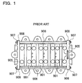
- a battery pack in which a plurality of rectangular cells are layered, is described in Japanese Utility Model Publication H3-32364-U ( 1991 ); and in such battery pack, a pair of end plates 905 are connected by means of a bolt 906 and the layered electric cells 901 are disposed between the end plates 905, as shown in Figure 1 .
- an auricular projection 908 is provided, at opposite sides of the end plate 905, for allowing the bolt 906 to be inserted through for connection of the bolt 906.
- the bolt 906 is inserted through the auricular projection 908, and a nut 907 is screwed onto a tip of the bolt to fix the end plate 905.
- Such structured battery pack suffers a drawback that a performance of the battery is lowered in accordance with its used state.
- a lithium-ion secondary cell is used as the rectangular cell in such structured battery pack, the battery pack suffers a drawback that an internal resistance of the cell increases in accordance with its used state, resulting in reduced output power. This is because the auricular projection is prone to be deformed, which makes it impossible to securely inhibit an outer casing of the cell from being expanded.
- an electrode expands at the time of an ordinary charging and discharging operations and at the time of overcharging operation, so that an interval between its positive and negative electrodes becomes widened.
- JP-H5-343105A ( 1993 ) describes a battery pack in which a metal bar is provided on opposite surfaces of layered rectangular cells, so that opposing ends of a metal strap are fixed to the metal bar by means of a set screw.
- an expansion of the rectangular cells is likely to deform the metal bar, and it is difficult to securely inhibit the expansion of the rectangular cells and securely inhibit a reduced performance of the cells.
- JP2001-507856T describes a battery pack in which a pair of end plates are provided on opposite surfaces of layered rectangular cells, so that a metal bar is fixed to the end plates by means of welding.
- Such battery pack suffers a drawback that it is difficult to adjust and fix the rectangular cells in an accurately compressed state, because the metal bar is fixed by means of welding.
- the present invention has been made with a view to overcome the drawbacks found in the conventional types of battery packs as described above. It is the primary object of the present invention to provide a battery pack in which layered rectangular cells are fixed in an ideal state so that a reduced performance of the cells in use can be prevented.
- the fixture component 4, 24, 34, 44, 54, 64, 74, 84, 94, 104 includes a pair of end plates 5, 25, 35, 45, 55, 65, 75, 85, 95, 105, disposed at opposite end faces of the layered rectangular cells, and a metal strap 6, 26, 36, 46, 56, 66, 76, 86, 96, 106 for fixing, in a compressed state, the layered rectangular cells to the end plates 5, 25, 35, 45, 55, 65, 75, 85, 95, 105 by connecting at an end of the metal strap.
- the metal strap 6, 26, 36, 46, 56, 66, 76, 106 has a folded portion at the end thereof, and the folded portion can be connected to an outer side of the end plate 5, 25, 35, 45, 55, 65, 75, 105.
- the rectangular cell can be so structured as to accommodate, in a casing, an electrode having positive and negative electrode plates layered, and the casing can be so structured as to seal an opening of an outer casing 1A by means of a sealing plate 1 B which has positive and negative electrode terminals 10 as well as having an opening 11 for a safety valve.
- the battery pack can be so constructed and arranged that the metal strap 6, 26, 36, 46, 56, 66, 76, 86, 96, 106 of the fixture component 4, 24, 34, 44, 54, 64, 74, 84, 94, 104 is disposed along opposite sides of the rectangular cells so as to connect the end of the strap to the end plate 5, 25, 35, 45, 55, 65, 75, 85, 95,105.
- the fixture component is not obstructive when gas coming out of an opened safety valve is exhausted outside, and is also not obstructive when a lead plate or a lead wire is connected to an output terminal. Therefore, while the layered rectangular cells are securely fixed by means of the fixture component, the gas coming out of the safety valve can be exhausted outside in an ideal state and also the lead plate or the lead wire can be electrically connected to the output terminal.
- the fixture component 4 includes a first metal strap 6A disposed along an upper end of the rectangular cell and a second metal strap 6B disposed along a lower end of the rectangular cell, so that the first metal strap 6A and the second metal strap 6B can have their ends connected to the upper and lower ends of the end plate 5.
- a rectangular cell is prone to expand at its center portion, and is less likely to expand at the upper end fixed to the sealing plate and at the lower end which is a bottom of the outer casing. This is because, while the center portion expands by the curving effect of a metal plate occupying the largest area in the outer casing, the upper and lower ends expands by the elongating effect of a metal plate in the sealing plate or in the outer casing bottom.
- the metal strap fixes, in a compressed state, the upper and lower ends of the rectangular cells having a smaller expansion.
- the metal strap 56, 66, 76, 86, 96 is in a folded state that the metal strap is folded into a rectangular shape so that a middle folded segment of the metal strap can be connected to one end plate 55A, 65A, 75A, 85A, 95A and both extremities of the metal strap can be connected to the other end plate 55B, 65B, 75B, 85B, 95B.
- the metal strap 6 can be a metal sheet that is processed into a grooved form.
- a fitting-in positioner 9, 29, 89, 99 can be provided at the side face of the end plate 5, 25, 35, 45, 55, 65, 75, 85, 95, 105 so as to allow the metal strap 6, 26, 36, 46, 56, 66, 76, 86, 96, 106 to be inserted therein and disposed in place.
- Such battery pack allows the metal strap to be connected to the end plate, without causing a positional displacement.
- the end of the metal strap 6, 26, 36, 46, 56, 66, 76, 86, 96, 106 can be connected to the end plate 5, 25, 35, 45, 55, 65, 75, 85, 95, 105 by any optional means of a bolt, nut, rivet or caulking structure.
- a spacer 2, 22 can be interposed between the rectangular cells for allowing an air-blowing duct 15 to be provided by using the spacer 2, 22.
- Such battery pack allows the electric cells to be efficiently cooled by sending air into the air-blowing duct.
- the air is blown, without being hampered by the metal strap, into the center portion of the rectangular cells where a temperature is easier to rise, so that such portion can be efficiently cooled.
- the battery pack of the present invention is suitable for a power supply unit that is mounted to an electric vehicle such as a hybrid car and an electric automobile so that electric power is supplied to a driving motor to drive the vehicle.
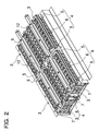
- FIGS. 1 through Figure 4 are views showing the battery pack in accordance with an embodiment of the present invention.
- Figure 2 and Figure 3 show a power supply unit provided with four units of battery packs, the power supply unit being used for a vehicle
- Figure 4 is a perspective view of the battery pack that is to be incorporated in such power supply units.
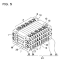
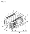
- Figure 5 through Figure 25 show the battery packs in accordance with alternative embodiments of the invention.
- a safety valve provided to the rectangular cells is not shown, for the purpose of simplifying the drawings.
- the battery packs shown in these drawings respectively include a battery block 3 in which a plurality of electric cells 1 being rectangular cells, and a fixture component 4, 24, 34, 44, 54, 64, 74, 84, 94, 104 for fixing the electric cells 1 constituting the battery block 3.
- the casing containing the layered rectangular cells is formed into a thin rectangular shape.
- the sealing plate 1 B as well is made of a metal sheet such as aluminum and aluminum alloy.
- positive and negative electrode terminals 10 are fixed through an insulation material to the opposite ends of the sealing plate.
- the positive and negative electrode terminals 10 are connected to the incorporated positive and negative electrode plates.
- the outer casing 1A made of the metal sheet is not connected through a lead wire to the electrodes. However, since the outer casing 1A is connected through an electrolytic solution to the electrode, the outer casing bears a midpoint potential with respect to the positive and negative electrodes.
- an opening for a safety value can also be provided at the bottom or side of the outer casing.
- an electrolytic solution is prone to be discharged when the safety valve is opened.
- the electrolytic solution is an electrically conductive liquid, and so when discharged, the solution is sometimes likely to cause a liquid-contacted portion to be short-circuited.
- the rectangular cell having the safety valve provided in the sealing plate 1 B at the casing can reduce the interior pressure by exhausting the gas through the safety valve being opened.
- a damage to be caused by the electrolytic solution can be reduced to minimum by limiting the exhaustion of the electrolytic solution.
- a vent duct 12 is provided atop of the battery pack so as to exhaust the gas, coming out of the safety valve, to the outside.
- the adjacent electrode terminals 10 are connected by means of a connector 13 so as to be interconnected in series. Further, a lead wire (not shown) is connected to the electrode terminal 10 in each of the rectangular cells. The lead wire is connected to a circuit board (not shown) on which a protection circuit is implemented for detecting a voltage of the cell. Although not shown, the circuit board is disposed superjacent to the battery pack, in Figure 4 .
- a spacer 2, 22 is interposed between the electric cells 1 being the rectangular cells.
- the spacer 2, 22 serves to insulate the outer casings 1 A of the adjacent rectangular cells, allowing an air-blowing duct 15 to be provided between the electric cells 1 so as to cool the cells. Therefore, the spacer 2, 22 is made by forming an insulation material such as plastics.
- the spacer 2, 22 is provided with a blower groove on opposite faces, and the air-blowing duct 15 is provided between the rectangular cells.
- the spacer 2, 22 is provided with the blower groove in a horizontal direction, namely such that the spacer is connected to the opposite sides of the rectangular cell.
- the air-blowing duct 15 provided in the spacer 2, 22 cools the rectangular cells by sending air in a horizontal direction.
- the electric cells 1, being the rectangular cells, which are layered through the spacer 2, 22 are fixed in place by using the fixture component 4, 24, 34, 44, 54, 64, 74, 84, 94, 104.
- the fixture component 4, 24, 34, 44, 54, 64, 74, 84, 94, 104 includes a pair of end plates 5, 25, 35, 45, 55, 65, 75, 85, 95, 105 disposed on the opposite end faces of the layered rectangular cells, and a metal strap 6, 26, 36, 46, 56, 66, 76, 86, 96, 106, the end of which is connected so as to fix the layered rectangular cells to the end plates 5, 25, 35, 45, 55, 65, 75, 85, 95, 105 in a compressed state.
- the end plate 5, 25, 35, 45, 55, 65, 75, 85, 95, 105 is made by forming a metal material such aluminum and aluminum alloy or by forming rigid plastics.
- the illustrated end plate 5, 25, 35, 45, 55, 65, 75, 85, 95, 105 is provided in an integral formation with stiffening ribs 16 extending vertically and horizontally on the outer side face.
- the end plate 5, 25, 35, 45, 55, 65, 75, 85, 95, 105 can be made greater in its bending strength by means of the stiffening ribs 16.
- the end plate with its excellent bending strength can effectively inhibit an expansion of the center portion of the rectangular cell. This is because, so long as the end plate connected to the metal strap is not deformed, the center portion of the rectangular cell does not expand.
- the end plate 5 25, 35, 45, 55, 65, 75, 85, 95, 105, its external contour is designed to be of a rectangular shape similar to the electric cell 1 being the rectangular cell so as to interpose the rectangular cell in a wide area.
- the rectangular end plate 5, 25, 35, 45, 55, 65, 75, 85, 95, 105 is designed to be of the same size as the rectangular cell or to be slightly larger than the rectangular cell.
- the illustrated end plate 5, 25, 35, 45, 55, 65, 75, 85, 95, 105 is provided with the blower groove on the surface opposite to the electric cell 1 and is provided with the air-blowing duct 15 with respect to the rectangular cells.
- the metal strap 6, 26, 36, 46, 56, 66, 76, 86, 96, 106 is connected through the set screw 7 to the end plate 5, 25, 45, 55, 75, 105, or is connected to the end plate 35, 65 by folding the strap end inwardly, or alternatively is connected to the end plate 85, 95 by screwing the nut 87 on the end of the metal strap 86 or by caulking the end of the metal strap 96.
- the end plate 5, 25, 45, 55, 75, 105, to which the metal strap 6, 26, 46, 56, 76, 106 is connected by means of the set screw 7, is formed of an internally threaded hole 8 into which the set screw 7 is screwed.
- the internally threaded hole 8 is defined on the outer surface of the end plate 5, 25, 45, 55, 75, 105, so that the metal strap 6, 26, 46, 56, 76, 106 is connected by screwing the set screw 7 which extends through the folded portion of the metal strap 6, 26, 46, 56, 76, 106.
- the first metal strap 6A disposed along the upper end of the rectangular cells and the second metal strap 6B disposed along the lower end of the rectangular cells are connected to the end plates 5.
- the internally threaded holes 8 are respectively defined on the upper and lower ends of the end plates, namely on the opposite sides of the outer surface.
- the upper and lower portions of the rectangular cells are respectively fixed by means of the metal straps 6.
- the battery pack may also be so designed as to dispose the metal strap 26, 36, 46, 56, 66, 76, 86, 96, 106 intermediate to the upper and lower portions, namely above and below the center portion.
- the end plate 25, 45, 55, 75, 105 for fixing the end of the metal strap 26, 46, 56, 76, 106 by means of the set screw 7 is formed of the internally threaded hole 8 defined at the connection point of the metal strap 26, 46, 56, 76, 106.
- the end plate 35 for fixing the end of metal strap 36 which is folded inwardly need not be formed of an internally threaded hole.
- a fitting-in positioner 9 for connecting the end of the metal strap 36 in place is provided on the side face of the end plate.
- the fitting-in positioner 9, being provided on the side face of the end plate 35, allows the metal strap 36 to be inserted through the fitting-in positioner by using the through hole which allows the metal strap 36 to be inserted through, so that the metal strap 36 is connected at the fitting-in positioner in place.
- the metal strap 36 inserted through has its end folded inwardly to be connected to the end plate 35.
- a caulking portion 96A provided at the tip of the metal strap 96 is inserted through the end plate, and the metal strap 96 is connected to the end plate 95 by caulking such that the opening tip of the caulking portion 96A is expanded.
- the end plate 95 is provided with a fitting-in positioner 99 for the through hole which is disposed in place by inserting the metal strap 96 through the hole, so that the caulking portion 96A protruding toward the outer side of the fitting-in positioner is caulked to connect the metal strap 96 to the end plate 95.
- fitting-in positioners 9, 29, 89, 99 are designed to be the fitting grooves for allowing the metal strap 26, 56 to be fitted in as shown in Figure 5 , Figure 6 , Figure 11 and Figure 12 , or are designed to be the through holes for allowing the metal strap 36, 46, 66, 76, 86, 96, 106 to be inserted through as shown in Figure 7 through Figure 10 and Figure 13 through Figure 25 , so that the metal strap 26, 36, 46, 56, 66, 76, 86, 96, 106 is disposed in place.
- the fitting-in positioner 9, 89, 99 for the through hole can fix the metal strap 36, 46, 66, 76, 86, 96, 106 in place in a manner that the metal strap is not displaced from the side face of the end plate 35, 45, 65, 75, 85, 95, 105. Therefore, the fitting-in positioner 9 for the through hole is suitable for the end plate 35, 65 being so structured as to fold the tip of the metal strap 36, 66 inwardly for connection. This is because the fitting-in positioner 9 can arrange the folded metal strap 36, 66 not to be displaced from the end plate 35, 65.
- the metal strap 6, 26, 36, 46, 56, 66, 76, 86, 96, 106 fixes the pair of end plates 5, 25, 35, 45, 55, 65, 75, 85, 95, 105 in a given size to fix the rectangular cells layered between them in a compressed state as predetermined.
- the metal strap 6, 26, 36, 46, 56, 66, 76, 86, 96, 106 is elongated under the effect of an expansion pressure of the rectangular cells, it becomes impossible to inhibit an expansion of the rectangular cells.
- the metal strap 6, 26, 36, 46, 56, 66, 76, 86, 96, 106 is made by processing a metal sheet of a strength that would not be elongated by the expansion pressure of the rectangular cells, i.e., a metal sheet like a stainless steel sheet and a steel sheet, including SUS304, to a width and thickness having a sufficient strength. Further, in the metal strap 6 shown in Figure 4 , a metal sheet is processed into a grooved form. The metal strap 6 thus formed has the feature that its bending strength can be made greater so that the layered rectangular cells, with its narrower width, can be securely fixed in a compressed state as predetermined.
- the metal strap 6, 26, 36, 46, 56, 66, 76, 86, 96, 106 is provided, at its end, with a folded portion, and the folded portion is connected to the end plate 5, 25, 35, 45, 55, 65, 75, 85, 95, 105.
- the folded portion is connected to the end plate 5, 25, 35, 45, 55, 65, 75, 85, 95, 105 by being formed of the through hole 17 for the set screw 7 or without being formed of such through hole.
- the folded portion defining the through hole 17 is connected by screwing the set screw 7, being inserted through the through hole 17, to the internally threaded hole 8 in the end plate 5, 25, 45, 55B, 75B, 105B.
- the metal strap 56, 66, 76, 86, 96 is folded into a rectangular shape so that the middle folded segment of the metal strap is connected to the outer surface of one end plate 55A, 65A, 75A, 85A, 95A and both extremities of the metal strap are connected to the other end plate 55B, 65B, 75B, 85B, 95B.
- the middle folded segment can be securely connected to the one end plate 55A, 65A, 75A, 85A, 95A.
- the metal strap 106 as shown in Figure 21 through Figure 25 , can also be fixed integrally with the end plate 105A. Such metal strap 106 can be connected to the one end plate 105A in the most firm manner.
- the above-described battery pack is assembled in the following procedure.
- the battery pack shown in Figure 2 through Figure 6 is assembled in the following procedure.
- the spacer 2, 22 is disposed between the electric cells 1 being the rectangular cells, then the spacer 2, 22 and the rectangular cells are layered to form the battery block 3, and the end plate 5, 25 is disposed on opposite sides of the battery block 3.
- the end plates 5, 25 on opposite sides are pressed by using a jig and are compressed until the interval of the end plates 5, 25 reaches a given size and is held in such state.
- the opposite ends of the metal strap 6, 26 are fixed to the end plate 5, 25.
- the illustrated metal strap 6, 26 is provided, at its opposite ends, with the folded portions defining the through hole 17.
- the metal strap 6, 26 is fixed to the end plate 5, 25 by screwing the set screw 7, being inserted through the through hole 17 at the folded portion, into the internally threaded hole 8 in the end plate 5, 25.
- the metal strap 26 is fitted in the fitting-in positioner 29 at the fitting-in groove provided on opposite sides of the end plate 25 and is disposed in place.
- All the metal straps 6, 26 are removed from the jig after being fixed to the end plate 5, 25.
- the layered rectangular cells are held in the compressed state by means of the pair of end plates 5, 25. Therefore, even when the rectangular cell tends to expand through an overcharging operation or the like, the interval between the opposite end plates 5, 25 remains unchanged, so that the expansion of the rectangular cells is inhibited by the end plates 5, 25.
- the metal strap 6, 26 since the opposite ends of the metal strap 6, 26 are fixed to the end plates 5, 25 by means of the set screw 7, the metal strap 6, 26 can be firmly fixed to the end plate 5, 25, and the metal strap 6, 26 allows the end plate 5, 25 to be held in a given size.
- the battery pack shown in Figure 7 through Figure 9 is assembled in the following procedure.
- the spacer 22 and the electric cells 1 being the rectangular cells are layered and the opposite end plates 35 are pressed by using a jig, being compressed until the interval of the end plates 35 reaches a given size and is held in such state.
- Process of Connecting the Metal Strap With the battery block 3 being held in its compressed state, the opposite ends of the metal strap 36 are fixed to the end plate 35.
- the illustrated metal strap 36 is provided, at its opposite ends, with the folded portions devoid of a through hole.
- the metal strap 36 is inserted through the fitting-in positioner 9 for the through hole defined on opposite sides of the end plate 35, with a folded portion being provided on one side only or without a folded portion being provided on the opposite sides.
- the end of the metal strap 36 thus inserted is folded inwardly, such folded portion is kept in close contact with the outer surface of the end plate 35, and the metal strap 36 is connected to the end plate 35.
- the folded portion is provided on one side, the tip of the metal strap 36 devoid of a folded portion is inserted through the fitting-in positioner 9 for the through hole, and the straight tip devoid of a folded portion is folded inwardly to be connected to the end plate 35.
- Process of Removing from the Jig The metal strap 36 is removed from the jig after being fixed to the end plate 35. Through the above procedures, the layered rectangular cells are held in a compressed state by means of the pair of end plates 35.
- the battery pack shown in Figure 10 is assembled in the same manner as the battery pack shown in Figure 7 through Figure 9 , except that, after the tip of the straight metal strap 46 devoid of a folded portion is inserted through the fitting-in positioner 9 for the through hole defined in the end plate 45, the strap is folded to form a folded portion, so that the set screw 7 is inserted through the through hole for such folded portion, the set screw 7 is screwed into the internally threaded hole 8 of the end plate 45, and the metal strap 46 is fixed to the end plate 45.
- the pair of end plates 55 is pressed by means of a jig to hold the battery block 3 in its compressed state, and the tip of the metal strap 56 is connected to one end plate 55B, for assembly.
- the metal strap 56 is folded in a manner where the metal strap is folded into a rectangular shape, and the metal strap is provided with the folded portion defining the through hole on opposite ends.
- the folded portion is disposed on the outer side of the other end plate 55A, while the portion is fitted in the fitting-in positioner 29 for the fitting groove being provided on the opposite sides of the end plate 55 to be disposed in place.
- the folded portion on the opposite ends is fixed to one end plate 55B by means of the set screw 7.
- the pair of end plates 55 can be firmly fixed by using two pieces of metal straps 56.
- the pair of end plates 65 are pressed by means of a jig to hold the battery block 3 in its compressed state, and the tip of the metal strap 66 is connected to one end plate 65B, for assembly.
- the metal strap 66 is folded in a manner where the metal strap is folded into a rectangular shape, but the opposite ends in a straight state devoid of a folded portion is connected to the end plate 65.
- the metal strap 66 is inserted through the through hole for the fitting-in positioner 9 being defined on the opposite sides of the end plate 65B, and the folded portion is disposed to the outer side of the other end plate 65A.
- the pair of end plate 75 is pressed by means of a jig to hold the battery block 3 in its compressed state, and the tip of the metal strap 76 is connected to one end plate 75B, for assembly.
- the metal strap 76 is folded in a manner where the metal strap is folded into a rectangular shape, but the opposite ends in a straight state devoid of a folded portion is connected to the end plate 75.
- the metal strap 76 is inserted through the through hole for the fitting-in positioner 9 being defined on the opposite sides of the end plate 75, and the folded portion is disposed to the outer side of the other end plate 75A.
- the straight tip of the metal strap 76 is allowed to protrude from the through hole for the fitting-in positioner 9, such protrusion is folded inwardly to form the folded portion, so that the set screw 7 is inserted through the through hole 17 (defined in advance) of this folded portion and the metal strap is fixed to one end plate 75B by means of the set screw 7.
- the pair of end plates 75 can be firmly fixed by two pieces of the metal strap 76.
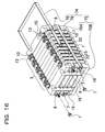
- the battery pack shown in Figure 17 and Figure 18 is assembled in the same manner as in the battery pack shown in Figure 13 through Figure 15 , except that the threaded portion 86A is provided at the tip of the metal strap 86 and the nut 87 is screwed onto the threaded portion 86A to connect the metal strap 86 to the end plate 85B. It should be noted, however, that the fitting-in positioner 89 for the through hole defined on the opposite sides of the end plate 85 is of an interior contour for allowing the tip of the metal strap 86 having the threaded portion 86A to be inserted through.
- the nut 87 is screwed onto the threaded portion 86A to fix the metal strap 86 to the end plate 85.
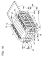
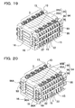
- the battery pack shown in Figure 19 and Figure 20 is assembled in the same manner as in the battery pack shown in Figure 13 through Figure 15 , except that a caulking portion 96A is provided at the tip of the metal strap 96, and the caulking portion 96A is caulked such that the opening tip of the caulking portion 96A is expanded to connect the metal strap 96 to the end plate 95.
- the fitting-in positioner 99 for the through hole defined on the opposite sides of the end plate 95 is of an interior contour for allowing the tip of the metal strap 96 having the caulking portion 96A to be inserted through. After the caulking portion 96A at the tip of the metal strap 96 is inserted through the through hole for the fitting-in positioner 99, the caulking portion 96A is caulked to connect the metal strap 96 to the end plate 95.
- the metal strap 106 is integrally connected to one end plate 105A. This battery pack is assembled in the following procedure.
- the spacer 22 is disposed between the electric cells 1 being the rectangular cells, the spacer 22 and the rectangular cells are layered to form the battery block 3, and the end plates 105 are disposed on the opposite sides of the battery block 3.
- the metal strap 106 connected to one end plate 105A is inserted through the through hole being the fitting-in positioner 9 for the other end plate 105B.
- the metal strap 106 connected to the end plate 105 is in a straight form without folding the tip.
- the end plates 105 on the opposite sides are pressed by means of a jig to hold the end plates in their compressed state until the interval between the end plates 105 reaches a given size.
- the tip of the metal strap 106 protruding from the through hole for the fitting-in positioner is folded inwardly, and such folded portion is allowed to be in close contact with the outer side of the end plate 105B.
- the through hole 17 is defined in advance so as to be positioned at the folded portion.
- the set screw 7 is inserted through the through hole 17 at the folded portion, and the set screw is screwed into the internally threaded hole 8 in the end plate 105B, so that the tip of the metal strap 106 is fixed to the end plate 105B.
- the opposite ends of the metal strap 106 are removed from the jig after being fixed to the end plate 105.
- the layered rectangular cells are held in their compressed state by means of the pair of end plates 105. Therefore, even if the rectangular cell tends to expand through an overcharging operation or the like, the interval between the opposite end plates 105 remains unchanged, so that the expansion of the rectangular cells is inhibited by the end plates 105.
- the metal strap 106 is firmly fixed to the end plate 105 for allowing the end plate 105 to be held by the metal strap in a given size.
Applications Claiming Priority (1)
| Application Number | Priority Date | Filing Date | Title |
|---|---|---|---|
| JP2007123686A JP2008282582A (ja) | 2007-05-08 | 2007-05-08 | 組電池 |
Publications (1)
| Publication Number | Publication Date |
|---|---|
| EP1990861A1 true EP1990861A1 (fr) | 2008-11-12 |
Family
ID=39717589
Family Applications (1)
| Application Number | Title | Priority Date | Filing Date |
|---|---|---|---|
| EP08008311A Withdrawn EP1990861A1 (fr) | 2007-05-08 | 2008-04-30 | Bloc-batteries |
Country Status (3)
| Country | Link |
|---|---|
| US (1) | US20080280194A1 (fr) |
| EP (1) | EP1990861A1 (fr) |
| JP (1) | JP2008282582A (fr) |
Cited By (18)
| Publication number | Priority date | Publication date | Assignee | Title |
|---|---|---|---|---|
| DE102009038404A1 (de) | 2009-08-24 | 2011-03-03 | Behr Gmbh & Co. Kg | Trägervorrichtung für eine elektrochemische Energiespeichereinheit |
| EP2323194A1 (fr) * | 2009-11-16 | 2011-05-18 | SB LiMotive Co., Ltd. | Module de batterie dotée d'une plaque terminale améliorée |
| EP2337113A1 (fr) * | 2009-12-18 | 2011-06-22 | SB LiMotive Co., Ltd. | Module de batterie dotée d'une retenue et procédé de fixation de la retenue |
| EP2339664A1 (fr) * | 2009-12-23 | 2011-06-29 | SB LiMotive Co., Ltd. | Bloc-batterie |
| WO2012028932A1 (fr) * | 2010-08-31 | 2012-03-08 | Toyota Jidosha Kabushiki Kaisha | Dispositif de stockage d'électricité |
| WO2012041588A1 (fr) * | 2010-09-30 | 2012-04-05 | Robert Bosch Gmbh | Procédé de serrage d'un accumulateur au lithium-ion, accumulateur au lithium-ion et véhicule automobile équipé d'un accumulateur au lithium-ion |
| US20120115004A1 (en) * | 2010-11-05 | 2012-05-10 | Shi-Dong Park | Battery module |
| DE102011003535A1 (de) * | 2011-02-02 | 2012-08-02 | Behr Gmbh & Co. Kg | Verspannungsvorrichtungen |
| CN102714292A (zh) * | 2010-01-27 | 2012-10-03 | 株式会社Lg化学 | 具有优良结构稳定性的电池组 |
| CN103703586A (zh) * | 2011-06-03 | 2014-04-02 | 丰田自动车株式会社 | 汇流条壳体、蓄电装置和车辆 |
| WO2014140060A1 (fr) * | 2013-03-12 | 2014-09-18 | Robert Bosch Gmbh | Logement constitué d'une structure métallique sous forme de cadre et d'une partie en plastique, destiné à contenir un paquet d'éléments de batterie |
| CN107026249A (zh) * | 2016-02-02 | 2017-08-08 | 北京长城华冠汽车科技股份有限公司 | 电池模块箱体及汽车 |
| RU2649315C1 (ru) * | 2015-12-18 | 2018-04-02 | Др. Инж. х.к. Ф. Порше Акциенгезелльшафт | Конструкция аккумуляторной батареи |
| EP3340340A4 (fr) * | 2016-07-25 | 2018-07-11 | LG Chem, Ltd. | Module de batterie et bloc-batterie le comprenant |
| EP3547390A1 (fr) * | 2018-03-30 | 2019-10-02 | Contemporary Amperex Technology Co., Limited | Plaque d'extrémité de module de batterie et module de batterie |
| WO2021022723A1 (fr) * | 2019-08-02 | 2021-02-11 | 深圳市雄韬锂电有限公司 | Ensemble élément de batterie, module de batterie, et bloc-batterie |
| CN112582725A (zh) * | 2019-09-12 | 2021-03-30 | 丰田自动车株式会社 | 电池模块和电池模块制造方法 |
| EP3790073A4 (fr) * | 2019-07-22 | 2021-03-31 | Jiangsu Contemporary Amperex Technology Limited | Bloc-batterie |
Families Citing this family (56)
| Publication number | Priority date | Publication date | Assignee | Title |
|---|---|---|---|---|
| CN2819483Y (zh) * | 2005-04-15 | 2006-09-20 | 金达时发展有限公司 | 薄板型锂电池的可组合连接架 |
| JP5261043B2 (ja) * | 2008-06-27 | 2013-08-14 | 三洋電機株式会社 | 車両用の組電池 |
| JP5340659B2 (ja) * | 2008-07-07 | 2013-11-13 | 三洋電機株式会社 | 車両用の組電池 |
| JP5272629B2 (ja) * | 2008-10-03 | 2013-08-28 | トヨタ自動車株式会社 | 組電池構造体の製造方法 |
| KR100906619B1 (ko) * | 2008-11-14 | 2009-07-10 | 한국에너지기술연구원 | 고체산화물형 연료전지용 금속분리판의 가열장치 및 이를 이용한 고체산화물 연료전지용 금속분리판의 열 플라즈마 코팅방법 |
| JP5405102B2 (ja) * | 2008-12-27 | 2014-02-05 | 三洋電機株式会社 | バッテリシステム |
| JP5490406B2 (ja) * | 2008-12-27 | 2014-05-14 | 三洋電機株式会社 | 車両用の電源装置 |
| AU2010208394A1 (en) * | 2009-01-27 | 2011-09-08 | Hologic, Inc. | Biomarkers for detection of neonatal sepsis in biological fluid |
| JP5442268B2 (ja) * | 2009-01-28 | 2014-03-12 | 三洋電機株式会社 | バッテリシステム |
| JP5428489B2 (ja) * | 2009-04-22 | 2014-02-26 | トヨタ自動車株式会社 | バッテリパック |
| EP2432044B1 (fr) * | 2009-05-14 | 2015-07-01 | GS Yuasa International Ltd. | Ensemble de batteries |
| JP5537111B2 (ja) * | 2009-09-30 | 2014-07-02 | 株式会社東芝 | 二次電池装置 |
| JP5649811B2 (ja) * | 2009-11-09 | 2015-01-07 | 三洋電機株式会社 | 車両用電源装置及びこれを備える車両並びに車両用電源装置の製造方法 |
| JP2011151006A (ja) * | 2009-12-25 | 2011-08-04 | Sanyo Electric Co Ltd | バッテリシステムおよびそれを備えた電動車両 |
| WO2011128949A1 (fr) * | 2010-04-16 | 2011-10-20 | トヨタ自動車株式会社 | Dispositif de stockage électrique |
| JP5516010B2 (ja) * | 2010-04-21 | 2014-06-11 | 日産自動車株式会社 | 組電池 |
| DE102010028194A1 (de) * | 2010-04-26 | 2011-10-27 | Robert Bosch Gmbh | Batterie mit einer Kühlplatte und Kraftfahrzeug mit einer entsprechenden Batterie |
| CN203300728U (zh) * | 2010-06-28 | 2013-11-20 | A123系统股份有限公司 | 具有保持带的电池组件 |
| JP5535794B2 (ja) * | 2010-06-30 | 2014-07-02 | 三洋電機株式会社 | 組電池 |
| US9203065B2 (en) * | 2010-08-10 | 2015-12-01 | Samsung Sdi Co., Ltd. | Battery module |
| KR101211336B1 (ko) * | 2010-09-20 | 2012-12-11 | 도요타지도샤가부시키가이샤 | 2차 전지용 조립 팔레트 및 2차 전지의 제조 방법 |
| US20130183571A1 (en) * | 2010-09-30 | 2013-07-18 | Sanyo Electric Co., Ltd. | Battery pack and vehicle including the same |
| AT510793B1 (de) * | 2010-11-17 | 2015-04-15 | Avl List Gmbh | Batterie |
| JP5813656B2 (ja) * | 2010-11-18 | 2015-11-17 | 三洋電機株式会社 | 組電池、組電池用セパレータ及びこれを備える車両 |
| JP5666274B2 (ja) * | 2010-12-04 | 2015-02-12 | 三洋電機株式会社 | 組電池及びこれを備える車両 |
| US9537190B2 (en) | 2011-01-06 | 2017-01-03 | Ford Global Technologies, Llc | Battery cell separators |
| US8709644B2 (en) | 2011-01-06 | 2014-04-29 | Ford Global Technologies, Llc | Battery cell separator |
| US8771864B2 (en) * | 2011-02-23 | 2014-07-08 | Samsung Sdi Co., Ltd. | Battery module |
| DE102011076575A1 (de) | 2011-05-27 | 2012-11-29 | Bmw Ag | Energiespeichermodul aus mehreren insbesondere prismatischen Speicherzellen und Verfahren zur Herstellung eines Energiespeichermoduls sowie Verfahren zur Herstellung einer Endplatte für ein Energiespeichermodul |
| DE102011076580A1 (de) | 2011-05-27 | 2012-11-29 | Bayerische Motoren Werke Aktiengesellschaft | Energiespeichermodul aus mehreren prismatischen Speicherzellen |
| DE102011076583A1 (de) | 2011-05-27 | 2012-11-29 | Bayerische Motoren Werke Aktiengesellschaft | Energiespeichermodul aus mehreren insbesondere prismatischen Speicherzellen und Verfahren zur Herstellung eines Energiespeichermoduls |
| US9634302B2 (en) | 2011-11-18 | 2017-04-25 | Hitachi Automotive Systems, Ltd. | Secondary battery module |
| EP2608309A1 (fr) * | 2011-12-21 | 2013-06-26 | Fortu Intellectual Property AG | Module de batterie doté d'un boîtier de module de batterie et de cellules de batterie |
| KR101285712B1 (ko) * | 2012-02-27 | 2013-07-12 | 세방전지(주) | 전지팩 케이스 |
| CN103373479B (zh) * | 2012-04-17 | 2015-12-02 | 上海航天测控通信研究所 | 一种宇航单机锁紧释放装置 |
| US9362536B2 (en) * | 2012-04-25 | 2016-06-07 | Robert Bosch Gmbh | Optimized module restraint system |
| KR101934396B1 (ko) | 2012-10-30 | 2019-01-02 | 삼성에스디아이 주식회사 | 배터리 조립체 |
| JP5761164B2 (ja) * | 2012-11-30 | 2015-08-12 | トヨタ自動車株式会社 | 組電池 |
| JP6224321B2 (ja) * | 2013-01-11 | 2017-11-01 | フタバ産業株式会社 | 組電池の拘束具、組電池の拘束部材、バッテリ |
| JP6174388B2 (ja) | 2013-06-19 | 2017-08-02 | 日立オートモティブシステムズ株式会社 | 電池モジュール |
| KR101794265B1 (ko) | 2013-07-18 | 2017-11-07 | 삼성에스디아이 주식회사 | 보강 비드부를 포함하는 배터리 팩 |
| CN105324866B (zh) | 2013-07-26 | 2017-12-19 | 新日铁住金株式会社 | 电池组用堆叠器和电池组 |
| JP6332725B2 (ja) * | 2013-09-27 | 2018-05-30 | 株式会社Gsユアサ | 蓄電装置 |
| JP6028231B2 (ja) | 2014-04-11 | 2016-11-16 | パナソニックIpマネジメント株式会社 | 組電池 |
| US9583747B2 (en) | 2015-01-08 | 2017-02-28 | Ford Global Technologies, Llc | Retention assembly for traction battery cell array |
| US11302973B2 (en) * | 2015-05-19 | 2022-04-12 | Ford Global Technologies, Llc | Battery assembly with multi-function structural assembly |
| WO2017057082A1 (fr) | 2015-10-02 | 2017-04-06 | 日立オートモティブシステムズ株式会社 | Batterie assemblée |
| DE102016202912A1 (de) * | 2016-02-25 | 2017-08-31 | Bayerische Motoren Werke Aktiengesellschaft | Zellmodul für eine Batterie eines Kraftfahrzeugs sowie Verfahren zum Herstellen eines solchen Zellmoduls |
| JP6565751B2 (ja) | 2016-03-15 | 2019-08-28 | 株式会社豊田自動織機 | 電池モジュール |
| JP6878975B2 (ja) * | 2017-03-17 | 2021-06-02 | 三洋電機株式会社 | 組電池 |
| KR102497037B1 (ko) * | 2017-12-06 | 2023-02-08 | 현대자동차주식회사 | 차량용 배터리팩 구조 |
| WO2019187316A1 (fr) * | 2018-03-30 | 2019-10-03 | 三洋電機株式会社 | Dispositif d'alimentation électrique et véhicule électrique pourvu d'un dispositif d'alimentation électrique |
| KR102580847B1 (ko) * | 2018-04-26 | 2023-09-19 | 에스케이온 주식회사 | 배터리 랙 |
| US10631429B2 (en) * | 2018-07-13 | 2020-04-21 | Ford Global Technologies, Llc | Vehicle power module assembly |
| US11502325B2 (en) * | 2019-12-19 | 2022-11-15 | Toyota Motor Engineering & Manufacturing North America, Inc. | Battery stack assemblies and methods for replacing a battery cell |
| CN212659640U (zh) | 2020-07-28 | 2021-03-05 | 厦门海辰新能源科技有限公司 | 电池模组固定组件及电池包 |
Citations (10)
| Publication number | Priority date | Publication date | Assignee | Title |
|---|---|---|---|---|
| JPH0332364U (fr) | 1989-08-03 | 1991-03-28 | ||
| JPH05343105A (ja) | 1992-06-08 | 1993-12-24 | Honda Motor Co Ltd | バッテリモジュール及びその温度調節用構造体 |
| EP0771037A1 (fr) * | 1995-10-24 | 1997-05-02 | Matsushita Electric Industrial Co., Ltd. | Accumulateur avec système de ventilation et de refroidissement |
| EP1081784A1 (fr) * | 1999-08-31 | 2001-03-07 | Matsushita Electronics Corporation | Bandes d'assemblage pour bloc de batterie |
| EP1091426A2 (fr) * | 1999-10-08 | 2001-04-11 | Matsushita Electric Industrial Co., Ltd. | Structure pour la connection d'une pluralité de batteries modulaires sous forme d'un bloc de batteries |
| EP1091438A2 (fr) * | 1999-10-08 | 2001-04-11 | Matsushita Electric Industrial Co., Ltd. | Bloc de batteries |
| JP2001507856A (ja) | 1997-01-13 | 2001-06-12 | オヴォニック バッテリー カンパニー インコーポレイテッド | 金属水素化物電池、該電池モジュール、並びに該電池パックにおける機械的、熱的改善 |
| EP1150364A2 (fr) * | 2000-04-28 | 2001-10-31 | Matsushita Electric Industrial Co., Ltd. | Batterie combinée |
| JP2004227788A (ja) * | 2003-01-20 | 2004-08-12 | Toyota Motor Corp | 車両用リチウムイオン組電池 |
| JP2007123686A (ja) | 2005-10-31 | 2007-05-17 | Canon Inc | 駆動装置及び方法、それを用いた位置検出装置及び露光装置並びにデバイス製造方法 |
Family Cites Families (16)
| Publication number | Priority date | Publication date | Assignee | Title |
|---|---|---|---|---|
| US118898A (en) * | 1871-09-12 | Improvement in confectionery-jars | ||
| US4020244A (en) * | 1975-02-18 | 1977-04-26 | Motorola, Inc. | Clamping structure for battery cells |
| FR2344133A1 (fr) * | 1976-03-09 | 1977-10-07 | Accumulateurs Fixes | Chassis pour batterie d'accumulateurs |
| JP3365577B2 (ja) * | 1994-05-27 | 2003-01-14 | 松下電器産業株式会社 | 密閉形ニッケル−水素蓄電池の単電池および単位電池 |
| JP3271494B2 (ja) * | 1995-10-24 | 2002-04-02 | 松下電器産業株式会社 | 積層密閉形アルカリ蓄電池 |
| US6146778A (en) * | 1997-07-25 | 2000-11-14 | 3M Innovative Properties Company | Solid-state energy storage module employing integrated interconnect board |
| JPH11120969A (ja) * | 1997-10-20 | 1999-04-30 | Matsushita Electric Ind Co Ltd | 集合型電池 |
| KR100497147B1 (ko) * | 2000-02-08 | 2005-06-29 | 주식회사 엘지화학 | 다중 중첩 전기화학 셀 및 그의 제조방법 |
| JP4581177B2 (ja) * | 2000-04-03 | 2010-11-17 | トヨタ自動車株式会社 | 電源装置 |
| JP2003045385A (ja) * | 2001-07-31 | 2003-02-14 | Yuasa Corp | 枠付二次電池および枠付組電池 |
| JP3934900B2 (ja) * | 2001-09-25 | 2007-06-20 | 矢崎総業株式会社 | 電源装置 |
| JP2005339932A (ja) * | 2004-05-26 | 2005-12-08 | Toyota Motor Corp | 組電池 |
| JP5113319B2 (ja) * | 2004-10-29 | 2013-01-09 | 富士重工業株式会社 | 蓄電体セルのパッケージ構造 |
| JP2006185815A (ja) * | 2004-12-28 | 2006-07-13 | Toyota Motor Corp | 電池パック |
| JP2006286547A (ja) * | 2005-04-04 | 2006-10-19 | Toyota Motor Corp | 蓄電モジュールとその支持ベルト |
| JP4915061B2 (ja) * | 2005-08-08 | 2012-04-11 | トヨタ自動車株式会社 | 電源パック構造 |
-
2007
- 2007-05-08 JP JP2007123686A patent/JP2008282582A/ja active Pending
-
2008
- 2008-04-30 EP EP08008311A patent/EP1990861A1/fr not_active Withdrawn
- 2008-05-01 US US12/149,436 patent/US20080280194A1/en not_active Abandoned
Patent Citations (12)
| Publication number | Priority date | Publication date | Assignee | Title |
|---|---|---|---|---|
| JPH0332364U (fr) | 1989-08-03 | 1991-03-28 | ||
| JPH05343105A (ja) | 1992-06-08 | 1993-12-24 | Honda Motor Co Ltd | バッテリモジュール及びその温度調節用構造体 |
| EP0771037A1 (fr) * | 1995-10-24 | 1997-05-02 | Matsushita Electric Industrial Co., Ltd. | Accumulateur avec système de ventilation et de refroidissement |
| JP2001507856A (ja) | 1997-01-13 | 2001-06-12 | オヴォニック バッテリー カンパニー インコーポレイテッド | 金属水素化物電池、該電池モジュール、並びに該電池パックにおける機械的、熱的改善 |
| EP1081784A1 (fr) * | 1999-08-31 | 2001-03-07 | Matsushita Electronics Corporation | Bandes d'assemblage pour bloc de batterie |
| EP1091426A2 (fr) * | 1999-10-08 | 2001-04-11 | Matsushita Electric Industrial Co., Ltd. | Structure pour la connection d'une pluralité de batteries modulaires sous forme d'un bloc de batteries |
| EP1091438A2 (fr) * | 1999-10-08 | 2001-04-11 | Matsushita Electric Industrial Co., Ltd. | Bloc de batteries |
| US20030118898A1 (en) * | 1999-10-08 | 2003-06-26 | Matsushita Electric Industrial Co., Ltd. | Battery pack |
| EP1619740A2 (fr) * | 1999-10-08 | 2006-01-25 | Matsushita Electric Industrial Co., Ltd. | Bloc de batteries |
| EP1150364A2 (fr) * | 2000-04-28 | 2001-10-31 | Matsushita Electric Industrial Co., Ltd. | Batterie combinée |
| JP2004227788A (ja) * | 2003-01-20 | 2004-08-12 | Toyota Motor Corp | 車両用リチウムイオン組電池 |
| JP2007123686A (ja) | 2005-10-31 | 2007-05-17 | Canon Inc | 駆動装置及び方法、それを用いた位置検出装置及び露光装置並びにデバイス製造方法 |
Cited By (34)
| Publication number | Priority date | Publication date | Assignee | Title |
|---|---|---|---|---|
| DE102009038404A1 (de) | 2009-08-24 | 2011-03-03 | Behr Gmbh & Co. Kg | Trägervorrichtung für eine elektrochemische Energiespeichereinheit |
| WO2011023515A1 (fr) | 2009-08-24 | 2011-03-03 | Behr Gmbh & Co. Kg | Dispositif de support pour unité électrochimique d'accumulation d'énergie |
| US8563153B2 (en) | 2009-11-16 | 2013-10-22 | Samsung Sdi Co., Ltd. | Battery module having improved end plate |
| EP2323194A1 (fr) * | 2009-11-16 | 2011-05-18 | SB LiMotive Co., Ltd. | Module de batterie dotée d'une plaque terminale améliorée |
| EP2337113A1 (fr) * | 2009-12-18 | 2011-06-22 | SB LiMotive Co., Ltd. | Module de batterie dotée d'une retenue et procédé de fixation de la retenue |
| EP2339664A1 (fr) * | 2009-12-23 | 2011-06-29 | SB LiMotive Co., Ltd. | Bloc-batterie |
| US9083029B2 (en) | 2009-12-23 | 2015-07-14 | Samsung Sdi Co., Ltd. | Battery pack |
| CN102714292A (zh) * | 2010-01-27 | 2012-10-03 | 株式会社Lg化学 | 具有优良结构稳定性的电池组 |
| EP2530765A2 (fr) * | 2010-01-27 | 2012-12-05 | LG Chem, Ltd. | Bloc-batteries présentant une stabilité structurelle remarquable |
| EP2530765A4 (fr) * | 2010-01-27 | 2013-07-03 | Lg Chemical Ltd | Bloc-batteries présentant une stabilité structurelle remarquable |
| US8808896B2 (en) | 2010-01-27 | 2014-08-19 | Lg Chem, Ltd. | Battery pack of excellent structural stability |
| CN102714292B (zh) * | 2010-01-27 | 2015-04-08 | 株式会社Lg化学 | 具有优良结构稳定性的电池组 |
| WO2012028932A1 (fr) * | 2010-08-31 | 2012-03-08 | Toyota Jidosha Kabushiki Kaisha | Dispositif de stockage d'électricité |
| WO2012041588A1 (fr) * | 2010-09-30 | 2012-04-05 | Robert Bosch Gmbh | Procédé de serrage d'un accumulateur au lithium-ion, accumulateur au lithium-ion et véhicule automobile équipé d'un accumulateur au lithium-ion |
| US10431784B2 (en) | 2010-09-30 | 2019-10-01 | Robert Bosch Gmbh | Method for clamping a lithium ion accumulator, lithium ion accumulator and motor vehicle having a lithium ion accumulator |
| US20120115004A1 (en) * | 2010-11-05 | 2012-05-10 | Shi-Dong Park | Battery module |
| US9455425B2 (en) * | 2010-11-05 | 2016-09-27 | Samsung Sdi Co., Ltd. | Battery module |
| DE102011003535A1 (de) * | 2011-02-02 | 2012-08-02 | Behr Gmbh & Co. Kg | Verspannungsvorrichtungen |
| CN103703586A (zh) * | 2011-06-03 | 2014-04-02 | 丰田自动车株式会社 | 汇流条壳体、蓄电装置和车辆 |
| WO2014140060A1 (fr) * | 2013-03-12 | 2014-09-18 | Robert Bosch Gmbh | Logement constitué d'une structure métallique sous forme de cadre et d'une partie en plastique, destiné à contenir un paquet d'éléments de batterie |
| US9947907B2 (en) | 2013-03-12 | 2018-04-17 | Robert Bosch Gmbh | Housing composed of a metal frame structure and a plastic component for accommodating a cell stack |
| DE102013204180B4 (de) | 2013-03-12 | 2021-07-08 | Robert Bosch Gmbh | Einhausung zum Aufnehmen eines Zellpakets, Batterie, Verfahren zum Herstellen einer Batterie und Verfahren zum Herstellen eines faserverstärkten Kunststoffbauteils für eine Einhausung einer Batterie |
| RU2649315C1 (ru) * | 2015-12-18 | 2018-04-02 | Др. Инж. х.к. Ф. Порше Акциенгезелльшафт | Конструкция аккумуляторной батареи |
| CN107026249A (zh) * | 2016-02-02 | 2017-08-08 | 北京长城华冠汽车科技股份有限公司 | 电池模块箱体及汽车 |
| EP3340340A4 (fr) * | 2016-07-25 | 2018-07-11 | LG Chem, Ltd. | Module de batterie et bloc-batterie le comprenant |
| US10608216B2 (en) | 2016-07-25 | 2020-03-31 | Lg Chem, Ltd. | Battery module and battery pack including same |
| US10720618B2 (en) | 2018-03-30 | 2020-07-21 | Contemporary Amperex Technology Co., Limited | End plate for battery module and battery module |
| EP3734686A1 (fr) * | 2018-03-30 | 2020-11-04 | Contemporary Amperex Technology Co., Limited | Plaque d'extrémité de module de batterie et module de batterie |
| EP3547390A1 (fr) * | 2018-03-30 | 2019-10-02 | Contemporary Amperex Technology Co., Limited | Plaque d'extrémité de module de batterie et module de batterie |
| EP3790073A4 (fr) * | 2019-07-22 | 2021-03-31 | Jiangsu Contemporary Amperex Technology Limited | Bloc-batterie |
| US11721869B2 (en) | 2019-07-22 | 2023-08-08 | Jiangsu Contemporary Amperex Technology Limited | Battery pack |
| WO2021022723A1 (fr) * | 2019-08-02 | 2021-02-11 | 深圳市雄韬锂电有限公司 | Ensemble élément de batterie, module de batterie, et bloc-batterie |
| CN112582725A (zh) * | 2019-09-12 | 2021-03-30 | 丰田自动车株式会社 | 电池模块和电池模块制造方法 |
| CN112582725B (zh) * | 2019-09-12 | 2023-04-07 | 丰田自动车株式会社 | 电池模块和电池模块制造方法 |
Also Published As
| Publication number | Publication date |
|---|---|
| JP2008282582A (ja) | 2008-11-20 |
| US20080280194A1 (en) | 2008-11-13 |
Similar Documents
| Publication | Publication Date | Title |
|---|---|---|
| EP1990861A1 (fr) | Bloc-batteries | |
| JP5405102B2 (ja) | バッテリシステム | |
| JP6117308B2 (ja) | 二次電池装置 | |
| US8828583B2 (en) | Battery module | |
| JP6032336B2 (ja) | 組電池及び組電池用セパレータ | |
| EP2226868B1 (fr) | Batterie rechargeable et module correspondant | |
| JP5490406B2 (ja) | 車両用の電源装置 | |
| EP1901368B1 (fr) | Module de batterie | |
| US8173288B2 (en) | Secondary battery | |
| US7951483B2 (en) | Assembled battery with inner and outer frames | |
| EP2416436B1 (fr) | Elément de détection de tension et module de batterie comprenant ledit élément | |
| US10629882B2 (en) | Battery module | |
| JP2013055070A (ja) | 組電池 | |
| EP1753058A2 (fr) | Module de batterie avec barrière cellulaire améliorée entre les cellules | |
| EP2838134A1 (fr) | Batterie, ensemble batterie, et véhicule | |
| US9112249B2 (en) | Power source apparatus having cooling path and gas discharge path | |
| JP2013020855A (ja) | 電源装置及び電源装置を備える車両 | |
| JP6862338B2 (ja) | 二次電池及び複数の二次電池を備えた組電池 | |
| KR101666876B1 (ko) | 이차 전지 및 그 모듈 | |
| CN110165099B (zh) | 电池组及电池组的制造方法 | |
| JP2013026191A (ja) | 電源装置 | |
| JP2004130910A (ja) | 電池モジュール | |
| JP2013055069A (ja) | 組電池の組立方法 | |
| KR101957403B1 (ko) | 셀 리드 연결 장치 및 이를 포함하는 배터리 모듈 | |
| JP4956937B2 (ja) | 鉛蓄電池 |
Legal Events
| Date | Code | Title | Description |
|---|---|---|---|
| PUAI | Public reference made under article 153(3) epc to a published international application that has entered the european phase |
Free format text: ORIGINAL CODE: 0009012 |
|
| AK | Designated contracting states |
Kind code of ref document: A1 Designated state(s): AT BE BG CH CY CZ DE DK EE ES FI FR GB GR HR HU IE IS IT LI LT LU LV MC MT NL NO PL PT RO SE SI SK TR |
|
| AX | Request for extension of the european patent |
Extension state: AL BA MK RS |
|
| 17P | Request for examination filed |
Effective date: 20081218 |
|
| AKX | Designation fees paid |
Designated state(s): DE FR IT |
|
| 17Q | First examination report despatched |
Effective date: 20140224 |
|
| STAA | Information on the status of an ep patent application or granted ep patent |
Free format text: STATUS: THE APPLICATION IS DEEMED TO BE WITHDRAWN |
|
| 18D | Application deemed to be withdrawn |
Effective date: 20140708 |