EP1990544A2 - Mehrstufen-Zentrifugalkompressor - Google Patents
Mehrstufen-Zentrifugalkompressor Download PDFInfo
- Publication number
- EP1990544A2 EP1990544A2 EP08008114A EP08008114A EP1990544A2 EP 1990544 A2 EP1990544 A2 EP 1990544A2 EP 08008114 A EP08008114 A EP 08008114A EP 08008114 A EP08008114 A EP 08008114A EP 1990544 A2 EP1990544 A2 EP 1990544A2
- Authority
- EP
- European Patent Office
- Prior art keywords
- suction passage
- annular suction
- shroud
- section area
- passage
- Prior art date
- Legal status (The legal status is an assumption and is not a legal conclusion. Google has not performed a legal analysis and makes no representation as to the accuracy of the status listed.)
- Granted
Links
Images


Classifications
-
- F—MECHANICAL ENGINEERING; LIGHTING; HEATING; WEAPONS; BLASTING
- F04—POSITIVE - DISPLACEMENT MACHINES FOR LIQUIDS; PUMPS FOR LIQUIDS OR ELASTIC FLUIDS
- F04D—NON-POSITIVE-DISPLACEMENT PUMPS
- F04D29/00—Details, component parts, or accessories
- F04D29/40—Casings; Connections of working fluid
- F04D29/42—Casings; Connections of working fluid for radial or helico-centrifugal pumps
- F04D29/44—Fluid-guiding means, e.g. diffusers
- F04D29/441—Fluid-guiding means, e.g. diffusers especially adapted for elastic fluid pumps
- F04D29/444—Bladed diffusers
-
- F—MECHANICAL ENGINEERING; LIGHTING; HEATING; WEAPONS; BLASTING
- F04—POSITIVE - DISPLACEMENT MACHINES FOR LIQUIDS; PUMPS FOR LIQUIDS OR ELASTIC FLUIDS
- F04D—NON-POSITIVE-DISPLACEMENT PUMPS
- F04D17/00—Radial-flow pumps, e.g. centrifugal pumps; Helico-centrifugal pumps
- F04D17/08—Centrifugal pumps
- F04D17/10—Centrifugal pumps for compressing or evacuating
- F04D17/12—Multi-stage pumps
- F04D17/122—Multi-stage pumps the individual rotor discs being, one for each stage, on a common shaft and axially spaced, e.g. conventional centrifugal multi- stage compressors
-
- F—MECHANICAL ENGINEERING; LIGHTING; HEATING; WEAPONS; BLASTING
- F04—POSITIVE - DISPLACEMENT MACHINES FOR LIQUIDS; PUMPS FOR LIQUIDS OR ELASTIC FLUIDS
- F04D—NON-POSITIVE-DISPLACEMENT PUMPS
- F04D29/00—Details, component parts, or accessories
- F04D29/40—Casings; Connections of working fluid
- F04D29/42—Casings; Connections of working fluid for radial or helico-centrifugal pumps
- F04D29/4206—Casings; Connections of working fluid for radial or helico-centrifugal pumps especially adapted for elastic fluid pumps
- F04D29/4213—Casings; Connections of working fluid for radial or helico-centrifugal pumps especially adapted for elastic fluid pumps suction ports
Definitions
- the present invention relates to a multistage centrifugal compressor, and more particularly, to a multistage centrifugal compressor including an annular suction passage upstream of a centrifugal impeller.
- Japanese Unexamined Patent Application Publication No. 2006-152994 discloses a multistage centrifugal compressor provided with an annular suction passage for guiding the flow at the outlet of the return channel in the former stage to the blade inlet, the centrifugal impeller, the diffuser disposed downstream of the centrifugal impeller, and the return channel for guiding the fluid at the outlet of the diffuser to the next stage.
- the annular suction passage has each shape at the hub side and the shroud side connected with a smooth curve, and has the passage cross-section area of the annular suction passage at the eye portion (where the radius of the passage at the shroud becomes minimum) set to be larger than that of the blade inlet so as to prevent deceleration of the flow passing from the eye portion to the blade inlet.
- the minimum radius of the suction passage at the hub side has to be reduced.
- the diameter of the rotary shaft has to be reduced to lower the critical speed of the rotary shaft system. The reduction in the critical speed may cause the problem of failing to increase the operation speed of the compressor.
- the minimum radius of the passage at the hub side may be increased to prevent reduction in the critical speed.
- the radius of the blade inlet is increased, and accordingly, the relative speed at the inlet is also increased to further bring the frictional loss against the impeller and the deceleration loss into the serious state. The efficiency of the compressor, thus, is deteriorated.
- a multistage centrifugal compressor includes a rotary shaft, a centrifugal impeller formed of a hub, a shroud, and blades in a radial cascade arrangement between the hub and shroud and attached to the rotary shaft in plural stages, an annular suction passage disposed upstream of the centrifugal impeller to guide a fluid flow from an inward radial direction to a blade inlet, a diffuser disposed downstream of the centrifugal impeller, and a return channel formed of a bend portion disposed downstream of the diffuser and a guide blade portion disposed downstream of the bend portion.
- An axial parallel portion is disposed in the annular suction passage at a hub side.
- the first aspect of the present invention provides the following preferred exemplary structures.
- a multistage centrifugal compressor includes a rotary shaft, a centrifugal impeller formed of a hub, a shroud, and blades in a radial cascade arrangement between the hub and shroud and attached to the rotary shaft in plural stages, an annular suction passage disposed upstream of the centrifugal impeller to guide a fluid flow from an inward radial direction to a blade inlet, a diffuser disposed downstream of the centrifugal impeller, and a return channel formed of a bend portion disposed downstream of the diffuser and a guide blade portion disposed downstream of the bend portion.
- a passage cross-section area of the annular suction passage at a position where a radius at a shroud side becomes minimum is made smaller than that of the blade inlet.
- the second aspect of the present invention provides the following preferred exemplary structure.
- the multistage centrifugal compressor according to the present invention is capable of improving the efficiency of the compressor without decreasing the critical speed of the rotary shaft system.
- FIG. 1 is a vertical section of an essential portion of the multistage centrifugal compressor according to the embodiment.
- Fig. 2 is a view showing the velocity vector derived from the viscous flow analysis on the cross-section of the impeller with the generally configured annular suction passage.
- Fig. 3 is a view showing the velocity vector derived from the viscous flow analysis on the cross-section of the impeller with the annular suction passage shown in Fig. 1 .
- the multistage centrifugal compressor 50 includes a rotary shaft 1, a centrifugal impeller 5b formed of a hub 4b, a shroud 3b, and blades 2b in a radial cascade arrangement between the plates 4b and 3b, an annular suction passage 6b disposed upstream of the centrifugal impeller 5b to guide the fluid flow from the inward radial direction to a blade inlet 14b, a diffuser 9b disposed downstream of the centrifugal impeller 5b, and a return channel 13b formed of a bend portion 10b disposed downstream of the diffuser 9b and a guide blade 11b disposed downstream of the bend portion 10b.
- Fig. 1 mainly shows the centrifugal impeller 5b at the second stage of the multistage centrifugal compressor 50, and each alphabet designated to the respective components, a, b, and c denotes the number of the stage in the order from the first stage.
- the respective components at the second stage will be described hereinafter.
- the rotary shaft 1 having both ends supported with bearings is connected to a drive source so as to be rotated at high speeds.
- the rotary shaft 1 is provided with the multistage centrifugal impellers 5b, 5c for accommodating the fluid from the axial direction so as to be discharged in the radial direction.
- a pair of partition plates 12b and 17b is provided at both sides of the centrifugal impeller 5b.
- the diffuser 9b defined by the pair of the partition plates 12b, 17b opposite with each other is disposed at the outer side of the impeller 5b in the radial direction.
- the bend portion 10b defined by the partition plate 12b and a casing 8 and the guide blade 11b defined by the partition plate 12b and a partition portion 8b of the casing 8 constitute the return channel 13b at the outlet of the diffuser 9b.
- the guide blade portion 11b is provided with plural guide blades.
- the annular suction passage 6b formed of the partition plate 12a in the former stage, a partition portion 8a in the former stage, a sleeve 7b at the hub side, the hub 4b, and the shroud 3b is formed between an outlet 19a of the return channel 13a in the former stage and the blade inlet 14b.
- the surface of the suction passage 6b at the shroud side has a smooth curve.
- the surface of the annular suction passage 6b at the hub side is formed by connecting a smooth curve portion at the inlet side, an axial parallel portion 15b from the middle of he smooth curve portion, and a smooth curve portion from the axial parallel portion 15b to the blade inlet 14b.
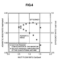
- the passage cross-section area of the annular suction passage 6b at an eye portion 16b (the position where the radius of the passage at the shroud side becomes minimum) is smaller than that at the blade inlet 14b, more specifically, approximately 70% to 95% of the passage cross-section area of the blade inlet 14b.
- the average flow velocity in the annular suction passage at the eye portion 16b is 1.45 to 1.05 times (1/0.7 to 1/0.95) higher than that at the blade inlet 14b.
- the flow at the outlet 19a of the return channel 13a in the former stage in the inward radial direction is guided through the annular suction passage 6b to the blade inlet 14b, and further to be accommodated into the blades 2b of the impeller 5b.
- the fluid with its pressure raised by the blades 2b of the impeller 5b is decelerated by the diffuser 9b such that the kinetic energy is converted into the pressure energy.
- the flow in the outward radial direction is changed to be directed to the inward radial direction through the return channel 13b, and is further guided to the annular suction passage 6c in the next stage.
- the fluid guided to the annular suction passage 6c in the next stage has its pressure raised by the centrifugal impeller 5c so as to be discharged to the diffuser 9c.
- the use of the axial parallel portion 15b on the surface of the annular suction passage 6b at the hub side makes it possible to increase the minimum radius of the surface of the passage at the hub side compared with the general case where the surface of the passage at the hub side is gently curved. Accordingly, the critical speed of the rotary shaft system may be increased, thus enhancing the compression performance by operating the compressor at high speeds.
- the diameter axial parallel portion 15b may further be enlarged to increase the number of stages of the multistage compressor.
- the radius of the blade inlet may be made smaller than the one in the conventional case.
- the relative speed at the blade inlet is reduced to decrease the impeller loss, the impeller efficiency, and further the compressor efficiency may be improved compared with the conventional machine.
- the turbulence in the fluid flow may occur.
- the cross-section area of the annular suction passage 6b at the eye portion 16b is made smaller than that of the blade inlet 14b, the flow velocity in the section with the reduced cross-section area may be decreased, thus increasing the loss.
- Figs. 2 and 3 show the velocity vector distributions on the cross-section of the impeller with respect to the generally configured annular suction passage, and the annular suction passage according to the embodiment, respectively.
- the velocity vector distribution is in good condition with substantially no large turbulence likewise the velocity vector of the generally configured annular suction passage.
- the passage cross-section area at the eye portion 16b is made smaller to be 70% to 95% of that of the blade inlet 14b. This makes it possible to increase the minimum radius of the surface of the passage at the hub side compared with the case where the annual suction passage is gently curved as in the conventional machine, or the axial parallel portion is formed simply on the surface of the annular suction passage at the hub side. This makes it possible to allow the compressor to be operated at high speeds, and to improve the efficiency of the compressor.
- the passage cross-section area at the eye portion 16b is made smaller to be 70% or less of that of the blade inlet, the flow may deviate from the wall surface of the annular suction passage at the shroud, thus deteriorating the performance of the compressor.
Applications Claiming Priority (1)
| Application Number | Priority Date | Filing Date | Title |
|---|---|---|---|
| JP2007125958A JP4910872B2 (ja) | 2007-05-10 | 2007-05-10 | 多段遠心圧縮機 |
Publications (3)
| Publication Number | Publication Date |
|---|---|
| EP1990544A2 true EP1990544A2 (de) | 2008-11-12 |
| EP1990544A3 EP1990544A3 (de) | 2009-06-17 |
| EP1990544B1 EP1990544B1 (de) | 2011-06-15 |
Family
ID=39577246
Family Applications (1)
| Application Number | Title | Priority Date | Filing Date |
|---|---|---|---|
| EP08008114A Expired - Fee Related EP1990544B1 (de) | 2007-05-10 | 2008-04-28 | Mehrstufen-Zentrifugalkompressor |
Country Status (3)
| Country | Link |
|---|---|
| US (1) | US8287236B2 (de) |
| EP (1) | EP1990544B1 (de) |
| JP (1) | JP4910872B2 (de) |
Cited By (2)
| Publication number | Priority date | Publication date | Assignee | Title |
|---|---|---|---|---|
| WO2011017857A1 (zh) * | 2009-08-13 | 2011-02-17 | Wang Hang | 旋转扩压壁式可调压气机装置 |
| CN110159595A (zh) * | 2019-05-29 | 2019-08-23 | 江苏大学 | 一种增高流道的多级泵反导叶以及流道增高方法 |
Families Citing this family (9)
| Publication number | Priority date | Publication date | Assignee | Title |
|---|---|---|---|---|
| DE102009052619A1 (de) * | 2009-11-11 | 2011-05-12 | Siemens Aktiengesellschaft | Zwischenboden für eine Radialturbomaschine |
| NO335019B1 (no) * | 2013-01-04 | 2014-08-25 | Typhonix As | Sentrifugalpumpe med koalescerende virkning, fremgangsmåte for utforming eller endring dertil, samt anvendelse |
| DE102015219556A1 (de) | 2015-10-08 | 2017-04-13 | Rolls-Royce Deutschland Ltd & Co Kg | Diffusor für Radialverdichter, Radialverdichter und Turbomaschine mit Radialverdichter |
| FR3087855B1 (fr) * | 2018-10-29 | 2020-11-13 | Danfoss As | Un turbocompresseur centrifuge ayant un trajet de flux de gaz comportant une chambre de detente |
| US11098730B2 (en) | 2019-04-12 | 2021-08-24 | Rolls-Royce Corporation | Deswirler assembly for a centrifugal compressor |
| US11286952B2 (en) | 2020-07-14 | 2022-03-29 | Rolls-Royce Corporation | Diffusion system configured for use with centrifugal compressor |
| US11441516B2 (en) | 2020-07-14 | 2022-09-13 | Rolls-Royce North American Technologies Inc. | Centrifugal compressor assembly for a gas turbine engine with deswirler having sealing features |
| US11578654B2 (en) | 2020-07-29 | 2023-02-14 | Rolls-Royce North American Technologies Inc. | Centrifical compressor assembly for a gas turbine engine |
| CN113107866B (zh) * | 2021-04-16 | 2023-04-21 | 山东天瑞重工有限公司 | 一种可调节轮背气压的真空泵 |
Citations (11)
| Publication number | Priority date | Publication date | Assignee | Title |
|---|---|---|---|---|
| FR644751A (fr) | 1926-12-13 | 1928-10-13 | Rateau Soc | Dispositif pour élever la vitesse critique d'un mobile de compresseur rotatif |
| GB460489A (en) | 1935-05-27 | 1937-01-28 | Escher Wyss Maschf Ag | Multistage centrifugal compressor or pump |
| GB690951A (en) | 1950-04-26 | 1953-04-29 | Carrier Engineering Co Ltd | Improvements in or relating to centrifugal compressors |
| FR1306368A (fr) | 1961-11-16 | 1962-10-13 | Laval Steam Turbine Co | Machine rotative à fluide |
| DE1428255A1 (de) | 1962-08-02 | 1969-01-09 | Alsacienne Constr Meca | Kreiselpumpe oder -verdichter |
| GB2181785A (en) | 1985-10-31 | 1987-04-29 | Proizv Ob Nevsky Z Im V I | Centrifugal compressor |
| EP0359514A2 (de) | 1988-09-14 | 1990-03-21 | Hitachi, Ltd. | Mehrstufiger Zentrifugalverdichter |
| DE3835341A1 (de) | 1988-10-19 | 1990-04-19 | Proizv Ob Nevskij Z Im V I | Kreiselverdichter mit horizontaler teilungsebene |
| EP0703368A2 (de) | 1994-09-20 | 1996-03-27 | Hitachi, Ltd. | Maschine für Fluidum |
| US6345503B1 (en) | 2000-09-21 | 2002-02-12 | Caterpillar Inc. | Multi-stage compressor in a turbocharger and method of configuring same |
| JP2006152994A (ja) | 2004-12-01 | 2006-06-15 | Mitsubishi Heavy Ind Ltd | 遠心圧縮機 |
Family Cites Families (5)
| Publication number | Priority date | Publication date | Assignee | Title |
|---|---|---|---|---|
| CH418137A (de) * | 1964-10-30 | 1966-07-31 | Sulzer Ag | Gehäuse einer mehrstufigen Zentrifugalpumpe |
| US5344285A (en) * | 1993-10-04 | 1994-09-06 | Ingersoll-Dresser Pump Company | Centrifugal pump with monolithic diffuser and return vane channel ring member |
| JPH11153097A (ja) * | 1997-11-21 | 1999-06-08 | Hitachi Ltd | 一軸多段遠心圧縮機及びターボ冷凍機 |
| JP4513432B2 (ja) * | 2004-07-07 | 2010-07-28 | 株式会社日立プラントテクノロジー | ターボ型流体機械及びこれに用いる段付シール装置 |
| JP4802786B2 (ja) * | 2006-03-20 | 2011-10-26 | 株式会社日立プラントテクノロジー | 遠心形ターボ機械 |
-
2007
- 2007-05-10 JP JP2007125958A patent/JP4910872B2/ja not_active Expired - Fee Related
-
2008
- 2008-04-28 EP EP08008114A patent/EP1990544B1/de not_active Expired - Fee Related
- 2008-05-08 US US12/117,288 patent/US8287236B2/en not_active Expired - Fee Related
Patent Citations (11)
| Publication number | Priority date | Publication date | Assignee | Title |
|---|---|---|---|---|
| FR644751A (fr) | 1926-12-13 | 1928-10-13 | Rateau Soc | Dispositif pour élever la vitesse critique d'un mobile de compresseur rotatif |
| GB460489A (en) | 1935-05-27 | 1937-01-28 | Escher Wyss Maschf Ag | Multistage centrifugal compressor or pump |
| GB690951A (en) | 1950-04-26 | 1953-04-29 | Carrier Engineering Co Ltd | Improvements in or relating to centrifugal compressors |
| FR1306368A (fr) | 1961-11-16 | 1962-10-13 | Laval Steam Turbine Co | Machine rotative à fluide |
| DE1428255A1 (de) | 1962-08-02 | 1969-01-09 | Alsacienne Constr Meca | Kreiselpumpe oder -verdichter |
| GB2181785A (en) | 1985-10-31 | 1987-04-29 | Proizv Ob Nevsky Z Im V I | Centrifugal compressor |
| EP0359514A2 (de) | 1988-09-14 | 1990-03-21 | Hitachi, Ltd. | Mehrstufiger Zentrifugalverdichter |
| DE3835341A1 (de) | 1988-10-19 | 1990-04-19 | Proizv Ob Nevskij Z Im V I | Kreiselverdichter mit horizontaler teilungsebene |
| EP0703368A2 (de) | 1994-09-20 | 1996-03-27 | Hitachi, Ltd. | Maschine für Fluidum |
| US6345503B1 (en) | 2000-09-21 | 2002-02-12 | Caterpillar Inc. | Multi-stage compressor in a turbocharger and method of configuring same |
| JP2006152994A (ja) | 2004-12-01 | 2006-06-15 | Mitsubishi Heavy Ind Ltd | 遠心圧縮機 |
Cited By (2)
| Publication number | Priority date | Publication date | Assignee | Title |
|---|---|---|---|---|
| WO2011017857A1 (zh) * | 2009-08-13 | 2011-02-17 | Wang Hang | 旋转扩压壁式可调压气机装置 |
| CN110159595A (zh) * | 2019-05-29 | 2019-08-23 | 江苏大学 | 一种增高流道的多级泵反导叶以及流道增高方法 |
Also Published As
| Publication number | Publication date |
|---|---|
| EP1990544A3 (de) | 2009-06-17 |
| JP4910872B2 (ja) | 2012-04-04 |
| US8287236B2 (en) | 2012-10-16 |
| US20080279680A1 (en) | 2008-11-13 |
| JP2008280924A (ja) | 2008-11-20 |
| EP1990544B1 (de) | 2011-06-15 |
Similar Documents
| Publication | Publication Date | Title |
|---|---|---|
| EP1990544B1 (de) | Mehrstufen-Zentrifugalkompressor | |
| EP2020509B1 (de) | Zentrifugalkompressor, Zentrifugallaufrad und Betriebsverfahren dafür | |
| JP5608062B2 (ja) | 遠心型ターボ機械 | |
| EP2138724B1 (de) | Zentrifugalkompressor mit schaufellosem Diffusor und entsprechender schaufelloser Diffusor | |
| RU2581686C2 (ru) | Радиальная диффузорная лопатка для центробежных компрессоров | |
| JP5879103B2 (ja) | 遠心式流体機械 | |
| JP5351941B2 (ja) | 遠心圧縮機とその羽根車およびその運転方法、羽根車の設計方法 | |
| JP2010144698A (ja) | 遠心圧縮機 | |
| JP4802786B2 (ja) | 遠心形ターボ機械 | |
| EP2149709A2 (de) | Mehrstufiger Rotationsverdichter | |
| JP2018135836A (ja) | 遠心圧縮機 | |
| JP6064003B2 (ja) | 遠心式流体機械 | |
| CN106662119B (zh) | 用于涡轮机的改进的涡管、包括所述涡管的涡轮机和操作的方法 | |
| JP5232721B2 (ja) | 遠心圧縮機 | |
| JP6860331B2 (ja) | ディフューザ、吐出流路、および遠心ターボ機械 | |
| KR20070095745A (ko) | 원심압축기 | |
| JPH1182389A (ja) | ターボ形流体機械 | |
| WO2022180902A1 (ja) | 多段遠心圧縮機 | |
| US20230375005A1 (en) | Centrifugal compressor | |
| WO2017170285A1 (ja) | 遠心羽根車、およびこれを備える遠心式流体機械 | |
| JP2023001450A (ja) | 多段遠心流体機械 | |
| JP6594019B2 (ja) | 入口案内羽根及び遠心圧縮機 | |
| JP2009264136A (ja) | 圧縮機のディフューザ | |
| JP2017172569A (ja) | 軸流圧縮機 |
Legal Events
| Date | Code | Title | Description |
|---|---|---|---|
| PUAI | Public reference made under article 153(3) epc to a published international application that has entered the european phase |
Free format text: ORIGINAL CODE: 0009012 |
|
| 17P | Request for examination filed |
Effective date: 20080428 |
|
| AK | Designated contracting states |
Kind code of ref document: A2 Designated state(s): AT BE BG CH CY CZ DE DK EE ES FI FR GB GR HR HU IE IS IT LI LT LU LV MC MT NL NO PL PT RO SE SI SK TR |
|
| AX | Request for extension of the european patent |
Extension state: AL BA MK RS |
|
| PUAL | Search report despatched |
Free format text: ORIGINAL CODE: 0009013 |
|
| AK | Designated contracting states |
Kind code of ref document: A3 Designated state(s): AT BE BG CH CY CZ DE DK EE ES FI FR GB GR HR HU IE IS IT LI LT LU LV MC MT NL NO PL PT RO SE SI SK TR |
|
| AX | Request for extension of the european patent |
Extension state: AL BA MK RS |
|
| RIC1 | Information provided on ipc code assigned before grant |
Ipc: F04D 29/42 20060101ALI20090512BHEP Ipc: F04D 17/12 20060101AFI20080714BHEP Ipc: F04D 29/54 20060101ALI20090512BHEP |
|
| AKX | Designation fees paid |
Designated state(s): DE IT |
|
| GRAP | Despatch of communication of intention to grant a patent |
Free format text: ORIGINAL CODE: EPIDOSNIGR1 |
|
| RIC1 | Information provided on ipc code assigned before grant |
Ipc: F04D 17/12 20060101AFI20101216BHEP Ipc: F04D 29/42 20060101ALI20101216BHEP |
|
| GRAS | Grant fee paid |
Free format text: ORIGINAL CODE: EPIDOSNIGR3 |
|
| GRAA | (expected) grant |
Free format text: ORIGINAL CODE: 0009210 |
|
| RIN1 | Information on inventor provided before grant (corrected) |
Inventor name: YAGI, MANABU Inventor name: KISHIBE, TADAHARU Inventor name: NISHIDA, HIDEO Inventor name: KUWANO, TETSUYA Inventor name: TANAKA, MASANORI Inventor name: KOBAYASHI, HIROMI |
|
| AK | Designated contracting states |
Kind code of ref document: B1 Designated state(s): DE IT |
|
| REG | Reference to a national code |
Ref country code: DE Ref legal event code: R096 Ref document number: 602008007537 Country of ref document: DE Effective date: 20110804 |
|
| PLBE | No opposition filed within time limit |
Free format text: ORIGINAL CODE: 0009261 |
|
| STAA | Information on the status of an ep patent application or granted ep patent |
Free format text: STATUS: NO OPPOSITION FILED WITHIN TIME LIMIT |
|
| 26N | No opposition filed |
Effective date: 20120316 |
|
| REG | Reference to a national code |
Ref country code: DE Ref legal event code: R097 Ref document number: 602008007537 Country of ref document: DE Effective date: 20120316 |
|
| REG | Reference to a national code |
Ref country code: DE Ref legal event code: R082 Ref document number: 602008007537 Country of ref document: DE Representative=s name: V. FUENER EBBINGHAUS FINCK HANO, DE |
|
| REG | Reference to a national code |
Ref country code: DE Ref legal event code: R082 Ref document number: 602008007537 Country of ref document: DE Representative=s name: V. FUENER EBBINGHAUS FINCK HANO, DE Effective date: 20140218 Ref country code: DE Ref legal event code: R081 Ref document number: 602008007537 Country of ref document: DE Owner name: HITACHI, LTD., JP Free format text: FORMER OWNER: HITACHI PLANT TECHNOLOGIES, LTD., TOKYO, JP Effective date: 20140218 |
|
| PGFP | Annual fee paid to national office [announced via postgrant information from national office to epo] |
Ref country code: DE Payment date: 20180417 Year of fee payment: 11 |
|
| PGFP | Annual fee paid to national office [announced via postgrant information from national office to epo] |
Ref country code: IT Payment date: 20180420 Year of fee payment: 11 |
|
| REG | Reference to a national code |
Ref country code: DE Ref legal event code: R119 Ref document number: 602008007537 Country of ref document: DE |
|
| PG25 | Lapsed in a contracting state [announced via postgrant information from national office to epo] |
Ref country code: DE Free format text: LAPSE BECAUSE OF NON-PAYMENT OF DUE FEES Effective date: 20191101 |
|
| PG25 | Lapsed in a contracting state [announced via postgrant information from national office to epo] |
Ref country code: IT Free format text: LAPSE BECAUSE OF NON-PAYMENT OF DUE FEES Effective date: 20190428 |