EP1989366B1 - Structure de toiture modulaire pour batiments - Google Patents
Structure de toiture modulaire pour batiments Download PDFInfo
- Publication number
- EP1989366B1 EP1989366B1 EP07713149A EP07713149A EP1989366B1 EP 1989366 B1 EP1989366 B1 EP 1989366B1 EP 07713149 A EP07713149 A EP 07713149A EP 07713149 A EP07713149 A EP 07713149A EP 1989366 B1 EP1989366 B1 EP 1989366B1
- Authority
- EP
- European Patent Office
- Prior art keywords
- edge portion
- panel
- edge portions
- edge
- adjacent
- Prior art date
- Legal status (The legal status is an assumption and is not a legal conclusion. Google has not performed a legal analysis and makes no representation as to the accuracy of the status listed.)
- Active
Links
- XLYOFNOQVPJJNP-UHFFFAOYSA-N water Substances O XLYOFNOQVPJJNP-UHFFFAOYSA-N 0.000 claims description 26
- 238000007789 sealing Methods 0.000 claims description 15
- 239000003795 chemical substances by application Substances 0.000 claims description 10
- 238000003780 insertion Methods 0.000 claims description 2
- 230000037431 insertion Effects 0.000 claims description 2
- 239000007788 liquid Substances 0.000 description 4
- 230000000295 complement effect Effects 0.000 description 2
- 239000000463 material Substances 0.000 description 2
- 239000002184 metal Substances 0.000 description 2
- 238000007493 shaping process Methods 0.000 description 2
- 238000004891 communication Methods 0.000 description 1
Images


Classifications
-
- E—FIXED CONSTRUCTIONS
- E04—BUILDING
- E04D—ROOF COVERINGS; SKY-LIGHTS; GUTTERS; ROOF-WORKING TOOLS
- E04D13/00—Special arrangements or devices in connection with roof coverings; Protection against birds; Roof drainage; Sky-lights
- E04D13/04—Roof drainage; Drainage fittings in flat roofs, balconies or the like
- E04D13/0404—Drainage on the roof surface
- E04D13/0445—Drainage channels
-
- E—FIXED CONSTRUCTIONS
- E04—BUILDING
- E04D—ROOF COVERINGS; SKY-LIGHTS; GUTTERS; ROOF-WORKING TOOLS
- E04D3/00—Roof covering by making use of flat or curved slabs or stiff sheets
- E04D3/36—Connecting; Fastening
- E04D3/361—Connecting; Fastening by specially-profiled marginal portions of the slabs or sheets
- E04D3/363—Connecting; Fastening by specially-profiled marginal portions of the slabs or sheets with snap action
-
- E—FIXED CONSTRUCTIONS
- E04—BUILDING
- E04D—ROOF COVERINGS; SKY-LIGHTS; GUTTERS; ROOF-WORKING TOOLS
- E04D13/00—Special arrangements or devices in connection with roof coverings; Protection against birds; Roof drainage; Sky-lights
- E04D13/04—Roof drainage; Drainage fittings in flat roofs, balconies or the like
- E04D13/0404—Drainage on the roof surface
- E04D13/0445—Drainage channels
- E04D2013/045—Drainage channels on inclined roofs
Definitions
- the present invention finds application in the field of building and particularly relates to a modular roof structure according to the preamble of claim 1.
- Modular roofing systems are known to be increasingly used for protection of buildings or other load-bearing structures, for both residential and industrial use, which systems are made of metal sheets having specially profiled edges, and are either pre-assembled or directly mounted to the roofing.
- European patent EP-B1-0964114 discloses a roof structure comprising a plurality of roofing panels to be anchored to the surface of a roof by means of suitable brackets. Each panel has a substantially planar middle portion and edge portions that can overlap and be stably sealably connected to edge portions of at least one adjacent panel to define a substantially continuous roofing.
- One object of the present invention is to overcome the above drawbacks, by providing a roof structure that is highly efficient and relatively cost-effective.
- a particular object is to provide a substantially flat roof structure, i.e. having no surface protrusion or unevenness.
- a further object is to provide a roof structure that allows to effectively drain water from its outer surface.
- the roof structure according to the present invention appears as a substantially continuous roof having no external unevenness or protrusion.
- the edge portions may be elastically deformable for snap fitting together and to the brackets.
- At least one deformable wall of an edge portion of a panel comprises at least one second protrusion which is designed for snap engagement into a corresponding recess or receptacle in the facing side wall of the other edge portion of an adjacent panel.
- the structure of the invention allows quick and effective connection of the panels with one another and with the brackets.
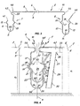
- the roof structure according to the invention which is generally designated by numeral 1, is particularly suitable as a roofing for both residential and industrial buildings.
- the first embodiment is shown in Figures 1 to 9
- the second embodiment is shown in Figures 10 to 19 .
- structure 1 comprises a plurality of roofing panels 2, generally made of metal, to be anchored to the surface of a roof T by means of suitable brackets 3.
- Panels 2 are substantially identical, except for any possible variation in length and/or width, wherefore they will be described hereinbelow with reference to one of them, there being understood that the same parts are present in all panels.
- adjacent panel elements will be designated by primed numerals 2, 2', 2" etc., and adjacent brackets will also be designated as 3, 3', 3". Unless otherwise stated, one of such parts may be only mentioned, by its unprimed numeral, there being understood that its designation and reference also extends to all corresponding parts.
- each panel 2 is formed of a substantially planar middle portion 4 with an upwardly facing outer side 5 and a downwardly facing inner side 6 and two edge portions, preferably provided at the longitudinal ends, which are generally designated by numerals 7, 8.
- the edge portions 7, 8 of each panel 2 extend transversly to the middle portion 4 only from the inner side 6, i.e. the one facing toward the roof T.
- edge portion 7 of one panel 2 can overlap and be stably connected with the edge portion 8' of the adjacent panel 2' to define a substantially continuous roofing surface, as viewed from the outside, i.e. on the side 5.
- the end portions 7, 8 may have complementary shapes to be snap fitted together and with the brackets 3, to provide stable anchorage and high wheatherproofness, such as rain water or the like, to prevent dangerous leakages into the building.
- the panels 2, 2', 2" may only contact the brackets 3, 3', 3" at the end edge portions 7, 7'; 8, 8'.
- the structure 1 may be solely composed of the panels 2, 2' and 2" and the brackets 3, 3', 3", with no additional elements, e.g. with no element interposed therebetween or with no element above the panels 2, 2', 2".
- one of the edge portions 8, 8' has a larger internal size than the other of the edge portions 7, 7' for accommodating the latter therein.
- the larger edge portion 8 has a free transverse margin 40 that is higher than the free transverse margin 41 of the other edge portion 7'.
- each of the edge portions 7, 7', 8, 8' of each panel 2, 2' may have snap engagement means 45 for easier and firmer connection.
- the snap engagement means 45 may be defined by deformable walls 9, 10; 12, 13 of each of the edge portions 7, 7', 8, 8'. Upon connection between the panels 2, 2' and/or between the latter and the brackets 3, the deformable walls 9, 10; 12, 13 will be deformed in response to a load stress P exerted on the panel, for optimized tightness. Nevertheless, it will be understood that only one of the deformable walls 9, 10; 12, 13 may be formed of a deformable material, without departure from the scope defined by the annexed claims.
- the edge portions 7, 8 may have first protrusions 43, 43 which are designed to be mutually opposed when the adjacent panels 2, 2' are connected to each other and to their respective bracket 3, as shown in Figures 4 and 13 .
- the structure 1 may include guide means 27 for guiding the mutual connection of the edge portions 7, 7', 8, 8' of adjacent panels 2, 2' and facilitating fixation thereof to the brackets 3.
- the guide means 27 may comprise a guide element 28 to be connected to an edge portion of a panel 2 and to a guide groove 30 in a corresponding bracket 3, and forming a predetermined angle with respect to the vertical axial plane ⁇ .
- the guide element 28 may have a substantially T-shaped cross section, with a transverse part 29 adapted to be slideably introduced in the guide groove 30 and a horizontal part 42.
- the latter may have a specially shaped step 32 for engaging a corresponding receptacle 33 formed at a first protrusion 43 of the edge portion 7', to have a retaining action thereon.
- the bracket 3 may include a prismatic member 50 having a base 51 and an inner axial cavity 25 which is designed to receive one of the edge portions 8, 8' of a panel 2, 2' for insertion and snap fit of the other smaller edge portion 7, 7' therein.
- the inner cavity 25 has side walls 23, 24 and a bottom wall 26 which are substantially symmetrical with respect to a vertical axial plane ⁇ , as shown in Figures 4 and 13 , and two upper edges 55, 56 as high as h 1 , h 2 .
- Bracket 3 may further have an upper protrusion 52 which is adapted to cooperate with a corresponding receptacle 53 formed in each panel 2 at the edge portion 8.
- each of the edge portions 7, 8 may be substantially U-shaped.
- the edge portion 7 may have side walls 9, 10 joined by a bottom portion 11, and the edge portion 8 may have side walls 12, 13 joined by a bottom portion 14.
- the side walls 9', 10' of the edge portion 7' of the panel 2' may have second transverse protrusions 15, 16 which are designed to stably cooperate with corresponding receptacles 17, 18 on the facing side walls 12, 13 of the edge portion 8 of the adjacent panel 2.
- the side walls 12, 13 of the edge portion 8 of the panel 2 may have a further pair of second transverse protrusions 19, 20 which are designed to stably cooperate with corresponding receptacles 21, 22 on the facing side walls 23, 24 of a complementary cavity 25 formed in the bracket 3.
- protrusions 19, 20 and the receptacles 17, 18 are actually coincident in the configuration as shown in Figures 1 to 9 , and formed by suitable modeling of the edge portion 8, it will be understood that, in practice, they may be also separate, i.e. one above the other, and the shapes and/or positions of the first and second protrusions, with their respective first and second receptacles, may be also different, even from each other, without departure from the scope as defined in the annexed claims.
- the bottom portions 11' and 14 and their respective side walls may define channels 60, 61 for drainage of liquids from the outer surface of the panels 2, 2' or liquids overflowing the edges 40, 41 thereof.
- the side walls 21, 22 and the bottom wall 26 of the cavity 25 may define a third drainage channel 62 for "capturing" water overflowing the first two channels.
- the collection capacity of the first channel 60 is determined by the height h 2 of the edge 41, and the capacity of the second channel 61 is determined by the height h 1 of the edge 40.
- the outer surface of the second protrusions 15', 16' may contact the inner surface of the first transverse recesses 17, 18 to define a sealing arrangement between the first channel 60 and the second channel 61.
- the edge portion 8 may be U-shaped, with the side walls 12 and 13 being joined together by the bottom portion 14, and the edge portion 7 may be J-shaped, with the side wall 10 being joined to the bottom wall.
- the side wall 10' of the edge portion 7' of the panel 2' may have a second transverse protrusion 65 which is designed to stably cooperate with a corresponding receptacle 66, which is formed on the side wall 13 of the edge portion 8 of the adjacent panel 2 by inward folding of the free edge 40.
- the bottom wall 9 is suitably shaped to stably cooperate with a corresponding receptacle 67 formed at the bottom portion 14 of the edge portion 8.
- bracket 3 may have an upper protrusion 52 which is adapted to cooperate with a corresponding receptacle 53 formed in each panel 2 at the edge portion 8, for the panel to be firmly held in position.
- the bottom portion 14 of the edge portion 8 has an underlying recess 70 which, in combination with the side walls 12 and 13, will define channels 71, 72 for drainage of liquids from the outer surface of the panels 2, 2' or liquids overflowing the edges 40, 41 thereof.
- the channels 71 and 72 are in communication with each other for better rain water drainage, and their collection capacity is defined by the height h 2 of the free edge 41.
- the recess 70 defines with the bottom wall 26 of the cavity 25 of the bracket 3, a third channel 73, whose collection capacity is defined by the height h 1 of the free edge 40.
- the outer surface of the bottom wall 9 may substantially contact the side wall 12 at the receptacle 67 to define a sealing arrangement between the first channel 72 and the second channel 71.
- the inner surface of the receptacle 66 of the edge portion 7 may substantially contact the outer surface of the protrusion 65 of the edge portion 8 to define a further sealing arrangement between the first and/or the second channel 71, 72 and the third channel 73.
- the upper protrusion 52 of the bracket 3 (and the corresponding receptacle 53) and the specially shaped step 32 of the horizontal part 42 of the guide element 28 (and the corresponding receptacle 33) will be so dimensioned as to allow the protrusions 43', 44 of the portions 7' and 8 of adjacent panels 2, 2' to be in mutual contact, to define a further sealing arrangement designed to prevent any leakage of rain water or similar agents into the underlying area.
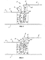
- the roof structure of the invention may be assembled by the operating steps that are shown in Figures 5 to 8 and 14 to 19 , relating to the first and second embodiments respectively.
- the bracket 3 is fixed to the roof, then the edge portion 8 of the panel 2 is anchored in the cavity 25 of the bracket 3, by exerting a substantially downwardly directed pressure P on the outer surface of the panel 2, preferably at the portion 8, until the walls 12, 13 coincide with the walls 23, 24, while stably connecting the protrusions 19, 20 to their respective receptacles 21, 22.
- the guide element 28 is fixed to the panel 2', by securing its end portion 32 in the corresponding receptacle 33 formed in the edge portion 7' of the panel 2'.
- the transverse part 29 is introduced in the groove 30 and the pressure P' is exerted on the panel 2', to first deform the wall 9', as shown in FIG. 6 , and then deform the wall 10', as shown in FIG. 7 , until the panels 2 and 2' are stably connected.
- the walls 9', 10' and the walls 12 and 13 of the panels 2 and 2' respectively coincide, and the protrusions 15, 16 stably fit in the receptacles 17, 18.
- the bottom portions 11' and 14 lie over each other.
- the structure may be disassembled by executing the above steps in the reverse order.
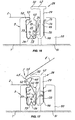
- the tool 34 as schematically shown in FIG. 9 may be used to facilitate disassembly. It comprises an L-shaped arm 35, which pivots at A 1 on a support element 36, and has a hook-like member 37 at its end, which is adapted to fit below the protrusion 33 to release the protrusions 15, 16 from the receptacles 17, 18 and disconnect the panel 2' from the panel 2.
- a force F 1 has to be exerted on the arm 35, as shown in FIG. 9 , so that the hook 37 translates upwards, in the direction of arrow F 2 so as to move with it the portion 7' of the panel 2', together with the plate 28.
- Figures 14 to 19 show various operating steps for assembling the second embodiment of the inventive roof structure.
- the panel 2 will be fixed to the bracket 3, and the edge portion 8 will be simultaneously introduced in the cavity 25.
- a pressure P needs simply be exerted on the outer side 5 of the panel, while causing the deformation of the walls 12 and/or 13 until the upper protrusion 52 of the bracket 3 fits in its respective receptacle 53, as shown in Figures 14 and 15 .
- the wall 12 of the edge portion 8 of the panel 2 will contact the side wall 23 of the cavity 25 of the bracket 3, the wall 13 will contact the lower portion of the wall 24 and the bottom portion 14 will face toward the bottom portion 26 of the bracket 3.
- the recess 70 of the bottom portion 14 and the bottom wall 26 of the bracket 3 will define the channel 73.
- the same recess 70 and the side wall 13 of the edge portion 8 will define the drainage channel 71.
- the wall 24 may have an inclined upper portion to define a lead-in surface for the side wall 13 of the edge portion 8 and help it to fit into the cavity 25.
- the guide element 28 will have to be positioned with the part 29 in the groove 30.
- the transverse part 29 may have a cog 75 at its bottom, which is designed to fit in a corresponding counter-shaped receptacle 76.
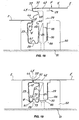
- the element 28 may be held in position with the part 42 in a substantially horizontal orientation and at a predetermined height, to facilitate later fixation of the panel 2'. The latter will be fixed to the element 28 with the step 32 fitting in the receptacle 33' and the edge portion 7' of the panel 2' also fitting in the cavity 25, as shown in Figures 17 and 18 .
- a pressure P' need simply be exerted on the outer side 5' of the panel 2', to cause the wall/s 9' and/or 10' to be deformed and translated downwards, to the final position as shown in Figure 19 .
- the bottom wall 9 of the edge portion 7' of the panel 2' will be introduced in the receptacle 67 until it coincides with the wall 12 and defines the channel 72, whereas the protrusion 65' of the side wall 10' will fit in the corresponding receptacle 66.
- the bottom wall 95 of the transverse part 29 contacts an abutment step 96 of the groove 30, which stops its downward translation. Also, in this position the protrusions 43' and 44 are in contact with each other, and thereby prevent atmospheric agent leakages.
- this second embodiment has various sealing arrangements against leakages of rain water or similar agents.
- a first sealing arrangement 100 defined by the contacting protrusions 43' and 44
- a second sealing arrangement 101 is defined by the bottom wall 9' of the edge portion 7' of the panel 2' and the wall 12 of the edge portion 8 of the panel 2
- a third sealing arrangement 102 is defined between the protrusion 65' of the edge portion 7' and the side wall 13 of the edge portion 8.
- the second channel 71 will cooperate with the first channel 72 for water drainage.
- the third channel 73 will cooperate with the first and the second channels 71, 72 for water drainage, thereby making it actually impossible for water to contact the slab of the roof T.
- appropriate shaping of the upper portion 97 of wall 24 is highly important, to provide an inclined surface for water to be conveyed into the third channel 73 and prevent it from contacting the roof T.
- the roof structure of the invention fulfills the intended objects and particularly meets the requirement of providing a substantially flat roof structure, i.e. having no surface protrusion or unevenness.
- the roofing has a substantially continuous appearance, having no external unevenness or protrusion, and further allows quick and effective assembly of the structure.
- edge portions 7, 8 By shaping the edge portions 7, 8 in such a manner that, with adjacent panels in operating positions and their edge portions in mutual contact, they can define drainage channels and sealing points, the structure is waterproofed in a highly reliable and effective manner.
Claims (15)
- Une structure de toit pour bâtiments comprenant plusieurs panneaux de toit (2 ; 2'), chaque panneau ayant une portion centrale (4 ; 4') substantiellement plane avec un côté externe (5 ; 5') tourné vers le haut et un côté interne (6 ; 6') tourné vers le bas et deux portions de bord non adjacentes (7, 8 ; 7', 8'), l'une desdites portions de bord (7, 7') étant profilée de manière appropriée pour se superposer partiellement et être reliée de façon stable à l'autre desdites portions de bord (8, 8') d'un panneau adjacent (2'), lesdites portions de bord non adjacentes (7, 8 ; 7', 8') s'étendant transversalement vers ladite portion centrale (4 ; 4'), exclusivement vers le bas de celle-ci, de telle sorte que ledit côté externe (5 ; 5') soit exclusivement visible de l'extérieur en l'absence de toute irrégularité ou saillie vers le haut, caractérisée en ce que ladite structure de toit comprend par ailleurs des fixations (3 ; 3') adaptées pour ancrer lesdits panneaux de toit à la plaque d'un toit (T) ou similaire.
- Structure selon la revendication 1, caractérisée en ce que lesdites portions de bord (7, 8 ; 7', 8') sont déformables élastiquement de manière à s'enclencher les unes dans les autres avec lesdites fixations (3 ; 3').
- Structure selon la revendication 1, caractérisée en ce qu'une desdites portions de bord (8, 8') présente des dimensions internes supérieures à celles de l'autre desdites portions de bord (7, 7') pour loger cette dernière à l'intérieur, ladite plus grande portion de bord (8, 8') ayant une marge transversale libre (40) plus haute que la marge transversale libre (41) de l'autre portion de bord (7, 7').
- Structure selon la revendication 1, caractérisée en ce que dans les zones de jonction (90, 91 ; 90', 91') avec leurs portions centrales respectives (4, 4'), les portions de bord (7, 8 ; 7', 8') présentent des premières saillies (43, 44) conçues pour être réciproquement opposées lorsque lesdits panneaux adjacents (2, 2') sont joints l'un à l'autre et à leur fixation respective (3).
- Structure selon une ou plusieurs des revendications de 1 à 4, caractérisée en ce que ladite fixation (3) inclut un corps prismatique (50) ayant une base (51) et une cavité axiale interne (25) conçue pour recevoir une des portions de bord (8, 8') d'un panneau (2, 2') pour l'insertion et l'enclenchement dans celle-ci de l'autre portion de bord (7, 7') la plus petite.
- Structure selon les revendications 5 et 4, caractérisée en ce que ladite fixation (3) présente une saillie supérieure (52) destinée à s'adapter à une cavité correspondante (53) définie par une desdites premières saillies (44) d'une portion de bord (8) dudit panneau (2).
- Structure selon une ou plusieurs des revendications de 1 à 6, caractérisée en ce qu'elle comprend des moyens de guidage (27) pour guider la jonction réciproque desdites portions de bord (7, 7', 8, 8') de panneaux adjacents (2, 2') et pour faciliter son ancrage auxdites fixations (3).
- Structure selon une ou plusieurs des revendications de 1 à 7, caractérisée en ce que chaque panneau comprend des moyens pour son engagement par enclenchement (45) dans un panneau adjacent, lesdits moyens d'engagement par enclenchement (45) étant définis par au moins une paroi déformable (9, 10 ; 12, 13) de chacune desdites portions de bord (7, 7', 8, 8'), cette dernière comprenant au moins une seconde saillie (15, 16, 65) conçue pour s'engager par enclenchement dans une cavité ou un creux correspondant (17, 18, 66) dans la paroi latérale opposée (9, 10 ; 12, 13) de l'autre portion de bord (7', 8') d'un panneau adjacent (2').
- Structure selon une ou plusieurs des revendications de 1 à 8, caractérisée en ce qu'une première desdites portions de bord (8) a une forme substantiellement en U, avec des parois latérales (12, 13) reliées entre elles par une portion de fond (14), la seconde portion de bord (7) ayant une forme substantiellement en J, avec une paroi latérale (10) reliée à la paroi de fond (9).
- Structure selon la revendication 9, caractérisée en ce que la paroi latérale (10') de ladite seconde portion de bord (7') d'un panneau (2') présente ladite seconde saillie transversale (65'), la paroi latérale opposée (13) de la première portion de bord (8) du panneau adjacent (2) présentant ladite cavité correspondante (66).
- Structure selon la revendication 9, caractérisée en ce que la paroi de fond (9') de ladite seconde portion de bord (7') d'un panneau (2') est profilée de façon appropriée pour s'adapter de manière stable dans une cavité correspondante (67) formée au niveau de la portion de fond (14) de la première portion de bord (8) du panneau adjacent (2).
- Structure selon la revendication 9, caractérisée en ce que la portion de fond (14) de la première portion de bord (8) présente une cavité (70) destinée à définir, avec lesdits bords latéraux (12, 13), un premier et un deuxième canal (72, 71) de drainage des eaux de pluie ou agents similaires, ladite cavité (70) définissant par ailleurs un troisième canal de drainage (73) avec la paroi de fond (26) de la cavité (25) de la fixation (3).
- Structure selon une ou plusieurs des revendications de 9 à 12, caractérisée en ce que la saillie supérieure (52) de la fixation (3) et la marche (32) de forme spéciale de la partie horizontale (42) de l'élément de guidage (28) sont configurées de telle sorte que les premières saillies (43', 44) des portions de bord (7', 8) de panneaux adjacents (2, 2') sont à contact réciproque, de manière à former une autre structure étanche (100) conçue pour empêcher toute fuite d'eau de pluie ou agents similaires dans la zone sous-jacente.
- Structure selon une ou plusieurs des revendications de 9 à 13, caractérisée en ce que la seconde portion de bord (7') d'un panneau et la première portion de bord (8) d'un panneau adjacent sont configurées de telle sorte que la paroi de fond (9') de ladite seconde portion de bord (7') et la paroi latérale (12) de ladite première portion de bord (8) sont substantiellement en contact réciproque au niveau de la cavité correspondante (67) pour former une deuxième structure étanche (101) destinée à empêcher toute fuite d'eau de pluie ou agents similaires dans la zone sous-jacente.
- Structure selon une ou plusieurs des revendications de 9 à 14, caractérisée en ce que la seconde portion de bord (7') d'un panneau et la première portion de bord (8) d'un panneau adjacent sont configurées de telle sorte que la seconde saillie (65') de ladite seconde portion de bord (7') et la paroi latérale (12) de ladite première portion de bord (8) sont substantiellement en contact réciproque au niveau de la cavité correspondante (66) pour former une troisième structure étanche (102) destinée à empêcher toute fuite d'eau de pluie ou agents similaires dans la zone sous-jacente.
Applications Claiming Priority (2)
| Application Number | Priority Date | Filing Date | Title |
|---|---|---|---|
| IT000046A ITVI20060046A1 (it) | 2006-02-14 | 2006-02-14 | Struttura di tetto modulare per edifici |
| PCT/IB2007/050454 WO2007093951A1 (fr) | 2006-02-14 | 2007-02-12 | Structure de toiture modulaire pour batiments |
Publications (2)
| Publication Number | Publication Date |
|---|---|
| EP1989366A1 EP1989366A1 (fr) | 2008-11-12 |
| EP1989366B1 true EP1989366B1 (fr) | 2009-07-29 |
Family
ID=38136153
Family Applications (1)
| Application Number | Title | Priority Date | Filing Date |
|---|---|---|---|
| EP07713149A Active EP1989366B1 (fr) | 2006-02-14 | 2007-02-12 | Structure de toiture modulaire pour batiments |
Country Status (6)
| Country | Link |
|---|---|
| EP (1) | EP1989366B1 (fr) |
| AT (1) | ATE437998T1 (fr) |
| DE (1) | DE602007001788D1 (fr) |
| ES (1) | ES2329844T3 (fr) |
| IT (1) | ITVI20060046A1 (fr) |
| WO (1) | WO2007093951A1 (fr) |
Cited By (2)
| Publication number | Priority date | Publication date | Assignee | Title |
|---|---|---|---|---|
| US11566426B2 (en) | 2019-11-26 | 2023-01-31 | Bmic Llc | Roofing panels with water shedding features |
| US11608640B2 (en) | 2021-05-25 | 2023-03-21 | Bmic Llc | Panelized roofing system |
Families Citing this family (6)
| Publication number | Priority date | Publication date | Assignee | Title |
|---|---|---|---|---|
| ITBO20130222A1 (it) * | 2013-05-14 | 2014-11-15 | Tecnocoperture Tangorra S R L | Dispositivo di copertura senza fissaggi esposti |
| ITPD20130323A1 (it) * | 2013-11-26 | 2015-05-27 | Fabris Srl | Copertura per edifici |
| ES2544683B1 (es) | 2014-01-27 | 2016-04-27 | Guives Girona, S.A. | Cubierta modular metálica para edificaciones |
| CN109898755A (zh) * | 2017-12-11 | 2019-06-18 | 美建建筑系统(中国)有限公司 | 一种设有支架的金属屋面 |
| EP3957805B1 (fr) * | 2020-08-20 | 2023-11-08 | Sandrini Metalli S.p.A. | Structure pour revêtement de surface |
| US20230323668A1 (en) * | 2020-09-18 | 2023-10-12 | Mauro Menegoli | Coating cover for roofs of buildings |
Family Cites Families (1)
| Publication number | Priority date | Publication date | Assignee | Title |
|---|---|---|---|---|
| FR2731029B1 (fr) * | 1995-02-24 | 1997-04-04 | Faconnage Et Construction En A | Element de toiture du type panneau en tole pliee |
-
2006
- 2006-02-14 IT IT000046A patent/ITVI20060046A1/it unknown
-
2007
- 2007-02-12 DE DE602007001788T patent/DE602007001788D1/de active Active
- 2007-02-12 WO PCT/IB2007/050454 patent/WO2007093951A1/fr active Application Filing
- 2007-02-12 AT AT07713149T patent/ATE437998T1/de not_active IP Right Cessation
- 2007-02-12 EP EP07713149A patent/EP1989366B1/fr active Active
- 2007-02-12 ES ES07713149T patent/ES2329844T3/es active Active
Cited By (3)
| Publication number | Priority date | Publication date | Assignee | Title |
|---|---|---|---|---|
| US11566426B2 (en) | 2019-11-26 | 2023-01-31 | Bmic Llc | Roofing panels with water shedding features |
| US11608640B2 (en) | 2021-05-25 | 2023-03-21 | Bmic Llc | Panelized roofing system |
| US11927019B2 (en) | 2021-05-25 | 2024-03-12 | Bmic Llc | Panelized roofing system |
Also Published As
| Publication number | Publication date |
|---|---|
| ES2329844T3 (es) | 2009-12-01 |
| EP1989366A1 (fr) | 2008-11-12 |
| ATE437998T1 (de) | 2009-08-15 |
| WO2007093951A1 (fr) | 2007-08-23 |
| DE602007001788D1 (de) | 2009-09-10 |
| ITVI20060046A1 (it) | 2007-08-15 |
Similar Documents
| Publication | Publication Date | Title |
|---|---|---|
| EP1989366B1 (fr) | Structure de toiture modulaire pour batiments | |
| US8713880B2 (en) | Light transmission panels, retaining clip and a combination thereof | |
| EP1651836B1 (fr) | Système de panneaux de transmission de lumière | |
| WO1999051835A1 (fr) | Element d'etancheite et cadre pour une partie de construction penetrant dans le toit | |
| US5644886A (en) | Roofing | |
| US4297825A (en) | Strut for space frames | |
| JP3773822B2 (ja) | 縦葺屋根材の接続構造 | |
| JP2524310B2 (ja) | 縦葺き屋根構造及びその施工法 | |
| KR102236142B1 (ko) | 조립성 향상과 침수 방지 기능을 갖는 건축용 루프 패널 | |
| JP3756254B2 (ja) | 建築用壁面板と屋根構造及び壁面構造 | |
| EP3404162A1 (fr) | Fenêtre de toit installée dans une structure de toit inclinée à l'aide d'un ensemble de solin et procédé de protection d'une fenêtre de toit contre les intempéries | |
| JP3861160B2 (ja) | 外壁の目地構造 | |
| JP3883545B2 (ja) | 屋外床板接続具及びそれを用いた屋外床並びに屋外床の施工方法 | |
| EP3404161B1 (fr) | Ensemble de solin et procédé de protection contre les intempéries d'une fenêtre de toit montée sur une surface de toit inclinée | |
| JPH0311290Y2 (fr) | ||
| JP6116057B2 (ja) | 屋根構造 | |
| JPS6013942Y2 (ja) | 採光用天窓装置 | |
| JP3080148B2 (ja) | 建築用外装材及び建築外装構造 | |
| JP2781957B2 (ja) | 内部連結型の縦葺き屋根 | |
| JPH0356579Y2 (fr) | ||
| JP3826250B2 (ja) | 金属折板屋根構造及び金属折板屋根の押え部材 | |
| JPS6133160Y2 (fr) | ||
| KR20090116895A (ko) | 용마루 부재 | |
| JPH0561304U (ja) | 外壁の水切り構造 | |
| JP2001032461A (ja) | 縦葺屋根材の接続構造 |
Legal Events
| Date | Code | Title | Description |
|---|---|---|---|
| PUAI | Public reference made under article 153(3) epc to a published international application that has entered the european phase |
Free format text: ORIGINAL CODE: 0009012 |
|
| 17P | Request for examination filed |
Effective date: 20080912 |
|
| AK | Designated contracting states |
Kind code of ref document: A1 Designated state(s): AT BE BG CH CY CZ DE DK EE ES FI FR GB GR HU IE IS IT LI LT LU LV MC NL PL PT RO SE SI SK TR |
|
| AX | Request for extension of the european patent |
Extension state: HR RS |
|
| GRAP | Despatch of communication of intention to grant a patent |
Free format text: ORIGINAL CODE: EPIDOSNIGR1 |
|
| GRAS | Grant fee paid |
Free format text: ORIGINAL CODE: EPIDOSNIGR3 |
|
| GRAA | (expected) grant |
Free format text: ORIGINAL CODE: 0009210 |
|
| AK | Designated contracting states |
Kind code of ref document: B1 Designated state(s): AT BE BG CH CY CZ DE DK EE ES FI FR GB GR HU IE IS IT LI LT LU LV MC NL PL PT RO SE SI SK TR |
|
| AX | Request for extension of the european patent |
Extension state: HR RS |
|
| REG | Reference to a national code |
Ref country code: GB Ref legal event code: FG4D |
|
| REG | Reference to a national code |
Ref country code: CH Ref legal event code: EP |
|
| REG | Reference to a national code |
Ref country code: IE Ref legal event code: FG4D |
|
| REF | Corresponds to: |
Ref document number: 602007001788 Country of ref document: DE Date of ref document: 20090910 Kind code of ref document: P |
|
| REG | Reference to a national code |
Ref country code: CH Ref legal event code: NV Representative=s name: ISLER & PEDRAZZINI AG |
|
| REG | Reference to a national code |
Ref country code: ES Ref legal event code: FG2A Ref document number: 2329844 Country of ref document: ES Kind code of ref document: T3 |
|
| PG25 | Lapsed in a contracting state [announced via postgrant information from national office to epo] |
Ref country code: IS Free format text: LAPSE BECAUSE OF FAILURE TO SUBMIT A TRANSLATION OF THE DESCRIPTION OR TO PAY THE FEE WITHIN THE PRESCRIBED TIME-LIMIT Effective date: 20091129 Ref country code: SE Free format text: LAPSE BECAUSE OF FAILURE TO SUBMIT A TRANSLATION OF THE DESCRIPTION OR TO PAY THE FEE WITHIN THE PRESCRIBED TIME-LIMIT Effective date: 20090729 Ref country code: LT Free format text: LAPSE BECAUSE OF FAILURE TO SUBMIT A TRANSLATION OF THE DESCRIPTION OR TO PAY THE FEE WITHIN THE PRESCRIBED TIME-LIMIT Effective date: 20090729 Ref country code: AT Free format text: LAPSE BECAUSE OF FAILURE TO SUBMIT A TRANSLATION OF THE DESCRIPTION OR TO PAY THE FEE WITHIN THE PRESCRIBED TIME-LIMIT Effective date: 20090729 Ref country code: FI Free format text: LAPSE BECAUSE OF FAILURE TO SUBMIT A TRANSLATION OF THE DESCRIPTION OR TO PAY THE FEE WITHIN THE PRESCRIBED TIME-LIMIT Effective date: 20090729 |
|
| PG25 | Lapsed in a contracting state [announced via postgrant information from national office to epo] |
Ref country code: SI Free format text: LAPSE BECAUSE OF FAILURE TO SUBMIT A TRANSLATION OF THE DESCRIPTION OR TO PAY THE FEE WITHIN THE PRESCRIBED TIME-LIMIT Effective date: 20090729 Ref country code: PL Free format text: LAPSE BECAUSE OF FAILURE TO SUBMIT A TRANSLATION OF THE DESCRIPTION OR TO PAY THE FEE WITHIN THE PRESCRIBED TIME-LIMIT Effective date: 20090729 Ref country code: LV Free format text: LAPSE BECAUSE OF FAILURE TO SUBMIT A TRANSLATION OF THE DESCRIPTION OR TO PAY THE FEE WITHIN THE PRESCRIBED TIME-LIMIT Effective date: 20090729 |
|
| PG25 | Lapsed in a contracting state [announced via postgrant information from national office to epo] |
Ref country code: BG Free format text: LAPSE BECAUSE OF FAILURE TO SUBMIT A TRANSLATION OF THE DESCRIPTION OR TO PAY THE FEE WITHIN THE PRESCRIBED TIME-LIMIT Effective date: 20091029 Ref country code: PT Free format text: LAPSE BECAUSE OF FAILURE TO SUBMIT A TRANSLATION OF THE DESCRIPTION OR TO PAY THE FEE WITHIN THE PRESCRIBED TIME-LIMIT Effective date: 20091129 |
|
| PG25 | Lapsed in a contracting state [announced via postgrant information from national office to epo] |
Ref country code: EE Free format text: LAPSE BECAUSE OF FAILURE TO SUBMIT A TRANSLATION OF THE DESCRIPTION OR TO PAY THE FEE WITHIN THE PRESCRIBED TIME-LIMIT Effective date: 20090729 Ref country code: CZ Free format text: LAPSE BECAUSE OF FAILURE TO SUBMIT A TRANSLATION OF THE DESCRIPTION OR TO PAY THE FEE WITHIN THE PRESCRIBED TIME-LIMIT Effective date: 20090729 Ref country code: RO Free format text: LAPSE BECAUSE OF FAILURE TO SUBMIT A TRANSLATION OF THE DESCRIPTION OR TO PAY THE FEE WITHIN THE PRESCRIBED TIME-LIMIT Effective date: 20090729 Ref country code: DK Free format text: LAPSE BECAUSE OF FAILURE TO SUBMIT A TRANSLATION OF THE DESCRIPTION OR TO PAY THE FEE WITHIN THE PRESCRIBED TIME-LIMIT Effective date: 20090729 |
|
| PG25 | Lapsed in a contracting state [announced via postgrant information from national office to epo] |
Ref country code: SK Free format text: LAPSE BECAUSE OF FAILURE TO SUBMIT A TRANSLATION OF THE DESCRIPTION OR TO PAY THE FEE WITHIN THE PRESCRIBED TIME-LIMIT Effective date: 20090729 Ref country code: BE Free format text: LAPSE BECAUSE OF FAILURE TO SUBMIT A TRANSLATION OF THE DESCRIPTION OR TO PAY THE FEE WITHIN THE PRESCRIBED TIME-LIMIT Effective date: 20090729 |
|
| PLBE | No opposition filed within time limit |
Free format text: ORIGINAL CODE: 0009261 |
|
| STAA | Information on the status of an ep patent application or granted ep patent |
Free format text: STATUS: NO OPPOSITION FILED WITHIN TIME LIMIT |
|
| 26N | No opposition filed |
Effective date: 20100503 |
|
| PG25 | Lapsed in a contracting state [announced via postgrant information from national office to epo] |
Ref country code: MC Free format text: LAPSE BECAUSE OF NON-PAYMENT OF DUE FEES Effective date: 20100301 Ref country code: GR Free format text: LAPSE BECAUSE OF FAILURE TO SUBMIT A TRANSLATION OF THE DESCRIPTION OR TO PAY THE FEE WITHIN THE PRESCRIBED TIME-LIMIT Effective date: 20091030 |
|
| PG25 | Lapsed in a contracting state [announced via postgrant information from national office to epo] |
Ref country code: IT Free format text: LAPSE BECAUSE OF NON-PAYMENT OF DUE FEES Effective date: 20100212 |
|
| PGRI | Patent reinstated in contracting state [announced from national office to epo] |
Ref country code: IT Effective date: 20110616 |
|
| PGFP | Annual fee paid to national office [announced via postgrant information from national office to epo] |
Ref country code: TR Payment date: 20120126 Year of fee payment: 6 |
|
| PG25 | Lapsed in a contracting state [announced via postgrant information from national office to epo] |
Ref country code: CY Free format text: LAPSE BECAUSE OF FAILURE TO SUBMIT A TRANSLATION OF THE DESCRIPTION OR TO PAY THE FEE WITHIN THE PRESCRIBED TIME-LIMIT Effective date: 20090729 |
|
| PG25 | Lapsed in a contracting state [announced via postgrant information from national office to epo] |
Ref country code: HU Free format text: LAPSE BECAUSE OF FAILURE TO SUBMIT A TRANSLATION OF THE DESCRIPTION OR TO PAY THE FEE WITHIN THE PRESCRIBED TIME-LIMIT Effective date: 20100130 |
|
| PGFP | Annual fee paid to national office [announced via postgrant information from national office to epo] |
Ref country code: IE Payment date: 20130226 Year of fee payment: 7 Ref country code: LU Payment date: 20130301 Year of fee payment: 7 |
|
| PG25 | Lapsed in a contracting state [announced via postgrant information from national office to epo] |
Ref country code: IT Free format text: LAPSE BECAUSE OF NON-PAYMENT OF DUE FEES Effective date: 20130212 |
|
| PGRI | Patent reinstated in contracting state [announced from national office to epo] |
Ref country code: IT Effective date: 20140102 |
|
| PG25 | Lapsed in a contracting state [announced via postgrant information from national office to epo] |
Ref country code: LU Free format text: LAPSE BECAUSE OF NON-PAYMENT OF DUE FEES Effective date: 20140212 |
|
| REG | Reference to a national code |
Ref country code: IE Ref legal event code: MM4A |
|
| PG25 | Lapsed in a contracting state [announced via postgrant information from national office to epo] |
Ref country code: IE Free format text: LAPSE BECAUSE OF NON-PAYMENT OF DUE FEES Effective date: 20140212 |
|
| REG | Reference to a national code |
Ref country code: FR Ref legal event code: PLFP Year of fee payment: 10 |
|
| REG | Reference to a national code |
Ref country code: FR Ref legal event code: PLFP Year of fee payment: 11 |
|
| PG25 | Lapsed in a contracting state [announced via postgrant information from national office to epo] |
Ref country code: TR Free format text: LAPSE BECAUSE OF NON-PAYMENT OF DUE FEES Effective date: 20140212 |
|
| REG | Reference to a national code |
Ref country code: FR Ref legal event code: PLFP Year of fee payment: 12 |
|
| PGFP | Annual fee paid to national office [announced via postgrant information from national office to epo] |
Ref country code: GB Payment date: 20220225 Year of fee payment: 16 Ref country code: DE Payment date: 20220225 Year of fee payment: 16 Ref country code: CH Payment date: 20220302 Year of fee payment: 16 |
|
| PGFP | Annual fee paid to national office [announced via postgrant information from national office to epo] |
Ref country code: NL Payment date: 20220224 Year of fee payment: 16 Ref country code: FR Payment date: 20220223 Year of fee payment: 16 Ref country code: ES Payment date: 20220301 Year of fee payment: 16 |
|
| PGFP | Annual fee paid to national office [announced via postgrant information from national office to epo] |
Ref country code: IT Payment date: 20221028 Year of fee payment: 17 |
|
| REG | Reference to a national code |
Ref country code: DE Ref legal event code: R119 Ref document number: 602007001788 Country of ref document: DE |
|
| REG | Reference to a national code |
Ref country code: CH Ref legal event code: PL |
|
| REG | Reference to a national code |
Ref country code: NL Ref legal event code: MM Effective date: 20230301 |
|
| GBPC | Gb: european patent ceased through non-payment of renewal fee |
Effective date: 20230212 |
|
| PG25 | Lapsed in a contracting state [announced via postgrant information from national office to epo] |
Ref country code: LI Free format text: LAPSE BECAUSE OF NON-PAYMENT OF DUE FEES Effective date: 20230228 Ref country code: CH Free format text: LAPSE BECAUSE OF NON-PAYMENT OF DUE FEES Effective date: 20230228 |
|
| PG25 | Lapsed in a contracting state [announced via postgrant information from national office to epo] |
Ref country code: NL Free format text: LAPSE BECAUSE OF NON-PAYMENT OF DUE FEES Effective date: 20230301 |
|
| PG25 | Lapsed in a contracting state [announced via postgrant information from national office to epo] |
Ref country code: GB Free format text: LAPSE BECAUSE OF NON-PAYMENT OF DUE FEES Effective date: 20230212 |
|
| PG25 | Lapsed in a contracting state [announced via postgrant information from national office to epo] |
Ref country code: GB Free format text: LAPSE BECAUSE OF NON-PAYMENT OF DUE FEES Effective date: 20230212 Ref country code: FR Free format text: LAPSE BECAUSE OF NON-PAYMENT OF DUE FEES Effective date: 20230228 Ref country code: DE Free format text: LAPSE BECAUSE OF NON-PAYMENT OF DUE FEES Effective date: 20230901 |
|
| REG | Reference to a national code |
Ref country code: ES Ref legal event code: FD2A Effective date: 20240404 |
|
| PG25 | Lapsed in a contracting state [announced via postgrant information from national office to epo] |
Ref country code: ES Free format text: LAPSE BECAUSE OF NON-PAYMENT OF DUE FEES Effective date: 20230213 |
|
| PG25 | Lapsed in a contracting state [announced via postgrant information from national office to epo] |
Ref country code: ES Free format text: LAPSE BECAUSE OF NON-PAYMENT OF DUE FEES Effective date: 20230213 |