EP1985378B1 - Dispositif d'aération de revêtements de sol - Google Patents
Dispositif d'aération de revêtements de sol Download PDFInfo
- Publication number
- EP1985378B1 EP1985378B1 EP08004131A EP08004131A EP1985378B1 EP 1985378 B1 EP1985378 B1 EP 1985378B1 EP 08004131 A EP08004131 A EP 08004131A EP 08004131 A EP08004131 A EP 08004131A EP 1985378 B1 EP1985378 B1 EP 1985378B1
- Authority
- EP
- European Patent Office
- Prior art keywords
- housing
- accordance
- housing part
- ventilation
- roll
- Prior art date
- Legal status (The legal status is an assumption and is not a legal conclusion. Google has not performed a legal analysis and makes no representation as to the accuracy of the status listed.)
- Not-in-force
Links
- 238000003475 lamination Methods 0.000 title claims 2
- 238000000576 coating method Methods 0.000 claims description 22
- 229920003002 synthetic resin Polymers 0.000 claims description 2
- 239000000057 synthetic resin Substances 0.000 claims description 2
- 238000009423 ventilation Methods 0.000 claims 9
- 239000011888 foil Substances 0.000 claims 1
- 238000005273 aeration Methods 0.000 abstract 1
- 238000013022 venting Methods 0.000 description 19
- 239000011248 coating agent Substances 0.000 description 14
- 230000002441 reversible effect Effects 0.000 description 4
- 238000004140 cleaning Methods 0.000 description 3
- 239000000945 filler Substances 0.000 description 2
- 238000005253 cladding Methods 0.000 description 1
- 238000004891 communication Methods 0.000 description 1
- 230000001771 impaired effect Effects 0.000 description 1
- 238000012423 maintenance Methods 0.000 description 1
- 238000000034 method Methods 0.000 description 1
- 239000000203 mixture Substances 0.000 description 1
- 238000002360 preparation method Methods 0.000 description 1
- 229920005989 resin Polymers 0.000 description 1
- 239000011347 resin Substances 0.000 description 1
Images

Classifications
-
- B—PERFORMING OPERATIONS; TRANSPORTING
- B05—SPRAYING OR ATOMISING IN GENERAL; APPLYING FLUENT MATERIALS TO SURFACES, IN GENERAL
- B05D—PROCESSES FOR APPLYING FLUENT MATERIALS TO SURFACES, IN GENERAL
- B05D3/00—Pretreatment of surfaces to which liquids or other fluent materials are to be applied; After-treatment of applied coatings, e.g. intermediate treating of an applied coating preparatory to subsequent applications of liquids or other fluent materials
- B05D3/12—Pretreatment of surfaces to which liquids or other fluent materials are to be applied; After-treatment of applied coatings, e.g. intermediate treating of an applied coating preparatory to subsequent applications of liquids or other fluent materials by mechanical means
-
- B—PERFORMING OPERATIONS; TRANSPORTING
- B05—SPRAYING OR ATOMISING IN GENERAL; APPLYING FLUENT MATERIALS TO SURFACES, IN GENERAL
- B05D—PROCESSES FOR APPLYING FLUENT MATERIALS TO SURFACES, IN GENERAL
- B05D5/00—Processes for applying liquids or other fluent materials to surfaces to obtain special surface effects, finishes or structures
-
- E—FIXED CONSTRUCTIONS
- E04—BUILDING
- E04F—FINISHING WORK ON BUILDINGS, e.g. STAIRS, FLOORS
- E04F21/00—Implements for finishing work on buildings
- E04F21/20—Implements for finishing work on buildings for laying flooring
- E04F21/24—Implements for finishing work on buildings for laying flooring of masses made in situ, e.g. smoothing tools
Definitions
- the invention relates to a device for venting of floor coatings, in particular of synthetic resin coatings or fillers, by means of a rotatably mounted in a housing breather roller which is equipped with a plurality of spikes.
- the venting has heretofore been done manually by passing a spiked air vent roller, which is attached to a handle or bar for ease of handling, over the bottom coating.
- a spiked air vent roller which is attached to a handle or bar for ease of handling, over the bottom coating.
- looped air vent rollers are also used.
- the processor has to attach special nail soles to the shoes in advance. The venting of a floor coating is therefore cumbersome and very time consuming.
- venting device of the aforementioned type, in which the venting roller is associated with a drive motor, which is in drive connection with this and can be operated remotely by means of a control unit via radio or infrared waves, and that the housing of the device has a three-point support.
- the housing is composed of a first and second housing part, which are hingedly connected to each other, wherein for pivoting one of the two housing parts an adjusting motor is provided, which is also remotely controllable by means of the control unit via radio or infrared waves.
- the articulated connection of the two housing parts allows the change of the direction of travel of the device.
- the drivable venting roller is divided and its common shaft is drivingly connected to the drive motor in this area between the two parts of the venting roller.
- the common shaft between the sub-breather rollers allows the simple drive connection between the drive motor and the breather roller.
- the three-point support of the housing is formed by the venting roller and a second venting roller, which is rotatably mounted, preferably in the pivotable second housing part.
- the two housing parts approximately in the middle of the housing or into each other and preferably to connect the pivotable second housing part via a vertically arranged pivot pin with the first housing part provided with the drive motor.
- the arrangement of the Articulated pin about in the middle of the housing allows a simple and effective change of the direction of travel of the device by pivoting one of the two housing parts.
- a reversible electric motor is provided for generating the adjusting movements of the second housing part, which cooperates via a pinion or racks with attached to the pivotable second housing part gear members.
- the reversible electric motor makes it possible to make changes in direction quickly and without difficulty.
- vent rollers are used interchangeably in each case in a receiving portion which is in the form of a cylinder section.
- a device according to the invention is formed, then it is possible in a simple manner and in a short time to vent a floor covering, without the space in which such a covering has been applied to a ceiling, must be entered. Rather, the device can be operated from outside the room and be moved more or less quickly over the covering. Through the spikes or the loops while a variety of holes is introduced into the lining, so that the trapped air can escape reliably. The venting of a floor coating with the aid of the proposed device is thus designed to be a pleasant interruption of often physically heavy work.
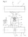
- the in the FIGS. 1 and 2 illustrated and designated 1 device 1 is used for venting a bottom coating 3, which is used to level balance on a screed covering 3 and are included in the air bubbles 4.
- a first venting roller 15 and a second venting roller 16 are rotatably mounted in a housing 11 of the device 1 in this case.
- the two breather rollers 15 bwz.16 are each equipped with spines 17 or loops.
- the first breather roller 15, which is formed divided and provided with a common shaft 18, a preferably electric drive motor 21 is associated with the first breather roller 15 and the common shaft 18 by means of a toothed belt 22 or a chain in drive connection.
- the drive motor 21 is remotely controllable by means of a control unit S, which cooperates with a built-in receiver 11 in the housing 23 via radio or infrared waves.
- the housing 11 is composed of a first and second housing part 12 and 13, which are pivotally connected to each other by means of a pivot pin 14.
- the orientation of the two housing parts 12 and 13 to each other, which can be changed by the pivoting of the housing part 13, is accomplished by means of an adjusting motor 24 which is designed as a reversible electric motor.
- a pinion 25 is driven, which is drivingly connected to gear members 26 on the second housing part 13, so that by the reversible adjusting motor 24, the pivoting of the two housing parts 13 is effected in both directions to a change in the direction of Trigger device 1.
- the adjusting motor 24 can also be operated remotely by means of the control unit S via radio or infrared waves.
- the second breather roller 16 is mounted in the second housing part 13 and thus forms with the first breather roller 12 a three-point support of the housing 11.
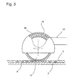
- the two breather rollers 15 and 16 are each interchangeably inserted in cylindrical receiving cups 19 of the two housing parts 12, 13.
- the receiving trays 19 are, like this Fig. 3 it can be seen on the inside preferably adhered panels in the form of films 20 attached.
- the two breather rollers 15 and 16 can thus be easily replaced, for example, for maintenance and cleaning purposes or to replace a breather roller 15, 16 with spikes 5 against a breather roller with loops.
- the films 20 on the inside of the receiving trays 19 without inserted breather rollers 15 and / or 16 can be easily replaced.
- the venting device 1 is self-propelled and remotely controllable. For venting a not yet cured floor coating in a building of the publisher need only set up the device 1 on the bottom coating 3 and set by means of the remote control unit S, which is in radio communication with the receiver 23 to the device 1, the direction and travel speed.
- the drive motor 21 is switchable, so that the device 1 can be moved both forward and backward. Accordingly, the device 1 can be moved remotely over the entire floor coating 3, so that it can be vented in a simple and quick manner.
Landscapes
- Engineering & Computer Science (AREA)
- Architecture (AREA)
- Coating Apparatus (AREA)
- Mechanical Engineering (AREA)
- Civil Engineering (AREA)
- Structural Engineering (AREA)
- Floor Finish (AREA)
Claims (8)
- Dispositif d'aération (1) de revêtements de sol (3), en particulier de revêtements en résine synthétique ou de mastics, moyennant un cylindre d'aération (15) tournant dans un boîtier (11) et équipé d'une multitude de picots (17),
caractérisé en ce
qu'au cylindre d'aération (15), il est assigné un moteur (21) qui l'entraîne et qui, moyennant une unité de commande S, est commandé à distance par radio ou par ondes infrarouges, et que le boîtier (11) du dispositif (1) comporte un appui à trois points. - Dispositif d'après la revendication 1,
caractérisé en ce que
le boîtier (11) est composé d'une première et d'une deuxième section (12, 13) liées par articulation et que pour le pivotement d'une des deux sections (13), il est prévu un moteur de réglage (24) commandé à distance par radio ou par ondes infrarouges. - Dispositif d'après les revendications 1 ou 2,
caractérisé en ce que
le cylindre d'aération entraîné (15) est divisé et que, entre les deux parties du cylindre d'aération (15), leur arbre commun (18) est lié par entraînement avec le moteur (21). - Dispositif d'après une ou plusieurs des revendications 1 à 3,
caractérisé en ce que
l'appui à trois points du boîtier (11) est formé par le cylindre d'aération (15) et par un deuxième cylindre d'aération (16) qui sont logés en rotation, de préférence, dans la deuxième partie pivotante du boîtier (13). - Dispositif d'après une ou plusieurs des revendications 2 à 4,
caractérisé en ce que,
à peu près au centre du boîtier (12), les deux parties du boîtier (12, 13) sont logés l'un sur ou dans l'autre, et que, via un pivot vertical (14), la deuxième partie pivotante du boîtier (13) est liée de préférence avec la première partie du boîtier (12) équipée du moteur d'entraînement (21). - Dispositif d'après une ou plusieurs des revendications 2 à 5,
caractérisé en ce que
pour réaliser les mouvements de réglage de la deuxième partie du boîtier (13), il est prévu un moteur électrique commutable (24) collaborant par l'intermédiaire d'un pignon (25) ou de crémaillères avec les éléments d'entraînement (26) prévus sur la deuxième partie pivotante du boîtier (13). - Dispositif d'après une ou plusieurs des revendications 1 à 6,
caractérisé en ce que
les cylindres d'aération échangeables (15, 16) sont insérés dans une coupelle de réception (19) conçue sous la forme d'une section de cylindre. - Dispositif d'après la revendication 7,
caractérisé en ce
qu'à l'intérieur, les coupelles de réception (19) sont munies de revêtements échangeables sous la forme de feuilles qui y sont fixées de préférence par collage.
Applications Claiming Priority (1)
| Application Number | Priority Date | Filing Date | Title |
|---|---|---|---|
| DE202007006144U DE202007006144U1 (de) | 2007-04-28 | 2007-04-28 | Vorrichtung zum Entlüften von Bodenbeschichtungen |
Publications (3)
| Publication Number | Publication Date |
|---|---|
| EP1985378A2 EP1985378A2 (fr) | 2008-10-29 |
| EP1985378A3 EP1985378A3 (fr) | 2008-11-26 |
| EP1985378B1 true EP1985378B1 (fr) | 2010-09-22 |
Family
ID=39577787
Family Applications (1)
| Application Number | Title | Priority Date | Filing Date |
|---|---|---|---|
| EP08004131A Not-in-force EP1985378B1 (fr) | 2007-04-28 | 2008-03-06 | Dispositif d'aération de revêtements de sol |
Country Status (3)
| Country | Link |
|---|---|
| EP (1) | EP1985378B1 (fr) |
| AT (1) | ATE481865T1 (fr) |
| DE (2) | DE202007006144U1 (fr) |
Families Citing this family (2)
| Publication number | Priority date | Publication date | Assignee | Title |
|---|---|---|---|---|
| CN112127244A (zh) * | 2020-10-19 | 2020-12-25 | 嵊州米想道路设施有限公司 | 一种自动排砖的路面铺砖装置 |
| CN113530148A (zh) * | 2021-07-31 | 2021-10-22 | 中冶建工集团有限公司 | 一种混凝土地坪的浇筑方法 |
Family Cites Families (4)
| Publication number | Priority date | Publication date | Assignee | Title |
|---|---|---|---|---|
| DE4323580C1 (de) * | 1993-07-14 | 1995-03-23 | Elias Lebessis | Reißwerkzeug |
| DE19817614A1 (de) * | 1998-04-21 | 1999-11-04 | Kvs Korrosions Und Verschleiss | Verfahren zum Beschichten eines Bodens |
| US7232277B2 (en) * | 2002-08-02 | 2007-06-19 | Chris Corbitt | Remotely-controlled concrete tool assembly |
| US20070006404A1 (en) * | 2005-07-08 | 2007-01-11 | Gooten Innolife Corporation | Remote control sweeper |
-
2007
- 2007-04-28 DE DE202007006144U patent/DE202007006144U1/de not_active Expired - Lifetime
-
2008
- 2008-03-06 DE DE502008001353T patent/DE502008001353D1/de active Active
- 2008-03-06 EP EP08004131A patent/EP1985378B1/fr not_active Not-in-force
- 2008-03-06 AT AT08004131T patent/ATE481865T1/de active
Also Published As
| Publication number | Publication date |
|---|---|
| DE202007006144U1 (de) | 2008-09-04 |
| ATE481865T1 (de) | 2010-10-15 |
| DE502008001353D1 (de) | 2010-11-04 |
| EP1985378A3 (fr) | 2008-11-26 |
| EP1985378A2 (fr) | 2008-10-29 |
Similar Documents
| Publication | Publication Date | Title |
|---|---|---|
| EP2164658B1 (fr) | Procédé de réalisation de composants tridimensionnels | |
| DE2818073C2 (de) | Tragbares Gerät zum Ablösen von auf einem Untergrund haftenden Bodenbelägen, Tapeten oder dergleichen | |
| WO2020225215A2 (fr) | Procédé et dispositif de traitement de surface | |
| DE3878681T2 (de) | Verfahren und vorrichtung zur behandlung einer oberflaeche. | |
| EP1985378B1 (fr) | Dispositif d'aération de revêtements de sol | |
| DE3006039C2 (de) | Verfahren und Vorrichtung zum Herstellen von auf vorhandene Bootsdecks aufzubringenden Stabdecks | |
| DE102016124892B4 (de) | Bearbeitungsvorrichtung mit einer programmtechnischen Steuerung | |
| EP2182115A1 (fr) | Dispositif de nivellement de ballast | |
| EP3025834B1 (fr) | Dispositif de guidage | |
| EP3939759B1 (fr) | Dispositif de maintien permettant de fixer des composants en béton dans un moule | |
| EP3252259B1 (fr) | Dispositif d'entrainement d'un volet roulant et volet roulant | |
| DE102019120375B3 (de) | Verfahren zum Betreiben einer Vorrichtung zur Bearbeitung, insbesondere Schmalseitenbearbeitung, von plattenförmigen Werkstücken | |
| DE202018102472U1 (de) | Vorrichtung zum Reinigen von Kettenplatten eines Kettenbandförderers einer Holzbearbeitungsmaschine | |
| DE202017103170U1 (de) | Vorrichtung zum Töpfern | |
| EP3434844B1 (fr) | Chariot à mortier | |
| EP2907635A1 (fr) | Affleureuse et procédé destiné à fraiser une arête | |
| DE2240511B2 (de) | Verfahren zur bearbeitung der oberflaeche von leder, haeuten u.dgl. | |
| DE19605577A1 (de) | Verfahren und Vorrichtung zum Verlegen von Bodenbelägen | |
| DE19700445B4 (de) | Verfahren und Vorrichtung zur Aufbringung unterschiedlichfarbiger Flocke auf Dichtungsprofile | |
| DE102010028683A1 (de) | Füllmaschine zum Abfüllen pastöser Masse | |
| WO2012155950A1 (fr) | Dispositif de fabrication de plaques de plâtre et procédé de fabrication d'une plaque de plâtre | |
| EP3354610B1 (fr) | Plieuse | |
| DE10317953B3 (de) | Vorrichtung und Verfahren zur Durchlaufbearbeitung von Werkstücken im Kantenbereich | |
| DE202006016922U1 (de) | Vorrichtung zum Aufbringen eines Haftmaterials auf eine Fliese oder fliesenähnliche Platte | |
| DE2329544C2 (de) | Vorrichtung zum maschinellen Verdichten und Ebnen von Estrichmassen |
Legal Events
| Date | Code | Title | Description |
|---|---|---|---|
| PUAI | Public reference made under article 153(3) epc to a published international application that has entered the european phase |
Free format text: ORIGINAL CODE: 0009012 |
|
| PUAL | Search report despatched |
Free format text: ORIGINAL CODE: 0009013 |
|
| AK | Designated contracting states |
Kind code of ref document: A2 Designated state(s): AT BE BG CH CY CZ DE DK EE ES FI FR GB GR HR HU IE IS IT LI LT LU LV MC MT NL NO PL PT RO SE SI SK TR |
|
| AX | Request for extension of the european patent |
Extension state: AL BA MK RS |
|
| AK | Designated contracting states |
Kind code of ref document: A3 Designated state(s): AT BE BG CH CY CZ DE DK EE ES FI FR GB GR HR HU IE IS IT LI LT LU LV MC MT NL NO PL PT RO SE SI SK TR |
|
| AX | Request for extension of the european patent |
Extension state: AL BA MK RS |
|
| RIC1 | Information provided on ipc code assigned before grant |
Ipc: A01D 41/00 20060101ALI20081023BHEP Ipc: E04F 21/20 20060101ALI20081023BHEP Ipc: B05D 3/12 20060101ALI20081023BHEP Ipc: A47L 11/32 20060101ALI20081023BHEP Ipc: A01D 37/00 20060101AFI20081023BHEP Ipc: A47L 11/33 20060101ALI20081023BHEP Ipc: C04B 41/48 20060101ALI20081023BHEP Ipc: A01D 42/00 20060101ALI20081023BHEP Ipc: E04F 21/22 20060101ALI20081023BHEP Ipc: A01D 39/00 20060101ALI20081023BHEP Ipc: E04F 21/00 20060101ALI20081023BHEP Ipc: E04F 15/12 20060101ALI20081023BHEP Ipc: E04F 21/24 20060101ALI20081023BHEP Ipc: B44C 7/02 20060101ALI20081023BHEP Ipc: A63H 30/04 20060101ALI20081023BHEP |
|
| 17P | Request for examination filed |
Effective date: 20090514 |
|
| AKX | Designation fees paid |
Designated state(s): AT BE BG CH CY CZ DE DK EE ES FI FR GB GR HR HU IE IS IT LI LT LU LV MC MT NL NO PL PT RO SE SI SK TR |
|
| 17Q | First examination report despatched |
Effective date: 20090723 |
|
| GRAP | Despatch of communication of intention to grant a patent |
Free format text: ORIGINAL CODE: EPIDOSNIGR1 |
|
| GRAS | Grant fee paid |
Free format text: ORIGINAL CODE: EPIDOSNIGR3 |
|
| GRAA | (expected) grant |
Free format text: ORIGINAL CODE: 0009210 |
|
| AK | Designated contracting states |
Kind code of ref document: B1 Designated state(s): AT BE BG CH CY CZ DE DK EE ES FI FR GB GR HR HU IE IS IT LI LT LU LV MC MT NL NO PL PT RO SE SI SK TR |
|
| REG | Reference to a national code |
Ref country code: GB Ref legal event code: FG4D Free format text: NOT ENGLISH |
|
| REG | Reference to a national code |
Ref country code: CH Ref legal event code: EP |
|
| REG | Reference to a national code |
Ref country code: IE Ref legal event code: FG4D Free format text: LANGUAGE OF EP DOCUMENT: GERMAN |
|
| REF | Corresponds to: |
Ref document number: 502008001353 Country of ref document: DE Date of ref document: 20101104 Kind code of ref document: P |
|
| PG25 | Lapsed in a contracting state [announced via postgrant information from national office to epo] |
Ref country code: NO Free format text: LAPSE BECAUSE OF FAILURE TO SUBMIT A TRANSLATION OF THE DESCRIPTION OR TO PAY THE FEE WITHIN THE PRESCRIBED TIME-LIMIT Effective date: 20101222 Ref country code: FI Free format text: LAPSE BECAUSE OF FAILURE TO SUBMIT A TRANSLATION OF THE DESCRIPTION OR TO PAY THE FEE WITHIN THE PRESCRIBED TIME-LIMIT Effective date: 20100922 Ref country code: LT Free format text: LAPSE BECAUSE OF FAILURE TO SUBMIT A TRANSLATION OF THE DESCRIPTION OR TO PAY THE FEE WITHIN THE PRESCRIBED TIME-LIMIT Effective date: 20100922 |
|
| REG | Reference to a national code |
Ref country code: NL Ref legal event code: VDEP Effective date: 20100922 |
|
| LTIE | Lt: invalidation of european patent or patent extension |
Effective date: 20100922 |
|
| PG25 | Lapsed in a contracting state [announced via postgrant information from national office to epo] |
Ref country code: PL Free format text: LAPSE BECAUSE OF FAILURE TO SUBMIT A TRANSLATION OF THE DESCRIPTION OR TO PAY THE FEE WITHIN THE PRESCRIBED TIME-LIMIT Effective date: 20100922 Ref country code: SI Free format text: LAPSE BECAUSE OF FAILURE TO SUBMIT A TRANSLATION OF THE DESCRIPTION OR TO PAY THE FEE WITHIN THE PRESCRIBED TIME-LIMIT Effective date: 20100922 Ref country code: HR Free format text: LAPSE BECAUSE OF FAILURE TO SUBMIT A TRANSLATION OF THE DESCRIPTION OR TO PAY THE FEE WITHIN THE PRESCRIBED TIME-LIMIT Effective date: 20100922 |
|
| PG25 | Lapsed in a contracting state [announced via postgrant information from national office to epo] |
Ref country code: SE Free format text: LAPSE BECAUSE OF FAILURE TO SUBMIT A TRANSLATION OF THE DESCRIPTION OR TO PAY THE FEE WITHIN THE PRESCRIBED TIME-LIMIT Effective date: 20100922 Ref country code: GR Free format text: LAPSE BECAUSE OF FAILURE TO SUBMIT A TRANSLATION OF THE DESCRIPTION OR TO PAY THE FEE WITHIN THE PRESCRIBED TIME-LIMIT Effective date: 20101223 Ref country code: LV Free format text: LAPSE BECAUSE OF FAILURE TO SUBMIT A TRANSLATION OF THE DESCRIPTION OR TO PAY THE FEE WITHIN THE PRESCRIBED TIME-LIMIT Effective date: 20100922 |
|
| REG | Reference to a national code |
Ref country code: IE Ref legal event code: FD4D |
|
| PG25 | Lapsed in a contracting state [announced via postgrant information from national office to epo] |
Ref country code: IE Free format text: LAPSE BECAUSE OF FAILURE TO SUBMIT A TRANSLATION OF THE DESCRIPTION OR TO PAY THE FEE WITHIN THE PRESCRIBED TIME-LIMIT Effective date: 20100922 |
|
| PG25 | Lapsed in a contracting state [announced via postgrant information from national office to epo] |
Ref country code: EE Free format text: LAPSE BECAUSE OF FAILURE TO SUBMIT A TRANSLATION OF THE DESCRIPTION OR TO PAY THE FEE WITHIN THE PRESCRIBED TIME-LIMIT Effective date: 20100922 Ref country code: PT Free format text: LAPSE BECAUSE OF FAILURE TO SUBMIT A TRANSLATION OF THE DESCRIPTION OR TO PAY THE FEE WITHIN THE PRESCRIBED TIME-LIMIT Effective date: 20110124 Ref country code: SK Free format text: LAPSE BECAUSE OF FAILURE TO SUBMIT A TRANSLATION OF THE DESCRIPTION OR TO PAY THE FEE WITHIN THE PRESCRIBED TIME-LIMIT Effective date: 20100922 Ref country code: NL Free format text: LAPSE BECAUSE OF FAILURE TO SUBMIT A TRANSLATION OF THE DESCRIPTION OR TO PAY THE FEE WITHIN THE PRESCRIBED TIME-LIMIT Effective date: 20100922 Ref country code: RO Free format text: LAPSE BECAUSE OF FAILURE TO SUBMIT A TRANSLATION OF THE DESCRIPTION OR TO PAY THE FEE WITHIN THE PRESCRIBED TIME-LIMIT Effective date: 20100922 Ref country code: CZ Free format text: LAPSE BECAUSE OF FAILURE TO SUBMIT A TRANSLATION OF THE DESCRIPTION OR TO PAY THE FEE WITHIN THE PRESCRIBED TIME-LIMIT Effective date: 20100922 Ref country code: IS Free format text: LAPSE BECAUSE OF FAILURE TO SUBMIT A TRANSLATION OF THE DESCRIPTION OR TO PAY THE FEE WITHIN THE PRESCRIBED TIME-LIMIT Effective date: 20110122 Ref country code: IT Free format text: LAPSE BECAUSE OF FAILURE TO SUBMIT A TRANSLATION OF THE DESCRIPTION OR TO PAY THE FEE WITHIN THE PRESCRIBED TIME-LIMIT Effective date: 20100922 |
|
| PG25 | Lapsed in a contracting state [announced via postgrant information from national office to epo] |
Ref country code: ES Free format text: LAPSE BECAUSE OF FAILURE TO SUBMIT A TRANSLATION OF THE DESCRIPTION OR TO PAY THE FEE WITHIN THE PRESCRIBED TIME-LIMIT Effective date: 20110102 |
|
| PLBE | No opposition filed within time limit |
Free format text: ORIGINAL CODE: 0009261 |
|
| STAA | Information on the status of an ep patent application or granted ep patent |
Free format text: STATUS: NO OPPOSITION FILED WITHIN TIME LIMIT |
|
| 26N | No opposition filed |
Effective date: 20110623 |
|
| PG25 | Lapsed in a contracting state [announced via postgrant information from national office to epo] |
Ref country code: DK Free format text: LAPSE BECAUSE OF FAILURE TO SUBMIT A TRANSLATION OF THE DESCRIPTION OR TO PAY THE FEE WITHIN THE PRESCRIBED TIME-LIMIT Effective date: 20100922 |
|
| BERE | Be: lapsed |
Owner name: REUTER, WERNER Effective date: 20110331 |
|
| REG | Reference to a national code |
Ref country code: DE Ref legal event code: R097 Ref document number: 502008001353 Country of ref document: DE Effective date: 20110623 |
|
| PG25 | Lapsed in a contracting state [announced via postgrant information from national office to epo] |
Ref country code: MC Free format text: LAPSE BECAUSE OF NON-PAYMENT OF DUE FEES Effective date: 20110331 |
|
| REG | Reference to a national code |
Ref country code: FR Ref legal event code: ST Effective date: 20111130 |
|
| PG25 | Lapsed in a contracting state [announced via postgrant information from national office to epo] |
Ref country code: MT Free format text: LAPSE BECAUSE OF FAILURE TO SUBMIT A TRANSLATION OF THE DESCRIPTION OR TO PAY THE FEE WITHIN THE PRESCRIBED TIME-LIMIT Effective date: 20100922 Ref country code: BE Free format text: LAPSE BECAUSE OF NON-PAYMENT OF DUE FEES Effective date: 20110331 |
|
| PG25 | Lapsed in a contracting state [announced via postgrant information from national office to epo] |
Ref country code: FR Free format text: LAPSE BECAUSE OF NON-PAYMENT OF DUE FEES Effective date: 20110331 |
|
| REG | Reference to a national code |
Ref country code: CH Ref legal event code: PL |
|
| GBPC | Gb: european patent ceased through non-payment of renewal fee |
Effective date: 20120306 |
|
| PG25 | Lapsed in a contracting state [announced via postgrant information from national office to epo] |
Ref country code: LI Free format text: LAPSE BECAUSE OF NON-PAYMENT OF DUE FEES Effective date: 20120331 Ref country code: GB Free format text: LAPSE BECAUSE OF NON-PAYMENT OF DUE FEES Effective date: 20120306 Ref country code: CH Free format text: LAPSE BECAUSE OF NON-PAYMENT OF DUE FEES Effective date: 20120331 |
|
| PG25 | Lapsed in a contracting state [announced via postgrant information from national office to epo] |
Ref country code: CY Free format text: LAPSE BECAUSE OF FAILURE TO SUBMIT A TRANSLATION OF THE DESCRIPTION OR TO PAY THE FEE WITHIN THE PRESCRIBED TIME-LIMIT Effective date: 20100922 Ref country code: LU Free format text: LAPSE BECAUSE OF NON-PAYMENT OF DUE FEES Effective date: 20110306 |
|
| PG25 | Lapsed in a contracting state [announced via postgrant information from national office to epo] |
Ref country code: BG Free format text: LAPSE BECAUSE OF FAILURE TO SUBMIT A TRANSLATION OF THE DESCRIPTION OR TO PAY THE FEE WITHIN THE PRESCRIBED TIME-LIMIT Effective date: 20101222 Ref country code: TR Free format text: LAPSE BECAUSE OF FAILURE TO SUBMIT A TRANSLATION OF THE DESCRIPTION OR TO PAY THE FEE WITHIN THE PRESCRIBED TIME-LIMIT Effective date: 20100922 |
|
| PG25 | Lapsed in a contracting state [announced via postgrant information from national office to epo] |
Ref country code: HU Free format text: LAPSE BECAUSE OF FAILURE TO SUBMIT A TRANSLATION OF THE DESCRIPTION OR TO PAY THE FEE WITHIN THE PRESCRIBED TIME-LIMIT Effective date: 20100922 |
|
| REG | Reference to a national code |
Ref country code: AT Ref legal event code: MM01 Ref document number: 481865 Country of ref document: AT Kind code of ref document: T Effective date: 20130306 |
|
| PG25 | Lapsed in a contracting state [announced via postgrant information from national office to epo] |
Ref country code: AT Free format text: LAPSE BECAUSE OF NON-PAYMENT OF DUE FEES Effective date: 20130306 |
|
| PGFP | Annual fee paid to national office [announced via postgrant information from national office to epo] |
Ref country code: DE Payment date: 20160428 Year of fee payment: 9 |
|
| REG | Reference to a national code |
Ref country code: DE Ref legal event code: R119 Ref document number: 502008001353 Country of ref document: DE |
|
| PG25 | Lapsed in a contracting state [announced via postgrant information from national office to epo] |
Ref country code: DE Free format text: LAPSE BECAUSE OF NON-PAYMENT OF DUE FEES Effective date: 20171003 |