EP1982943B1 - Dispositif de bobinage pour un poste de travail d'une machine textile fabriquant des bobines - Google Patents
Dispositif de bobinage pour un poste de travail d'une machine textile fabriquant des bobines Download PDFInfo
- Publication number
- EP1982943B1 EP1982943B1 EP20080006782 EP08006782A EP1982943B1 EP 1982943 B1 EP1982943 B1 EP 1982943B1 EP 20080006782 EP20080006782 EP 20080006782 EP 08006782 A EP08006782 A EP 08006782A EP 1982943 B1 EP1982943 B1 EP 1982943B1
- Authority
- EP
- European Patent Office
- Prior art keywords
- cross
- winding device
- creel
- winding
- bobbin
- Prior art date
- Legal status (The legal status is an assumption and is not a legal conclusion. Google has not performed a legal analysis and makes no representation as to the accuracy of the status listed.)
- Active
Links
Images
Classifications
-
- B—PERFORMING OPERATIONS; TRANSPORTING
- B65—CONVEYING; PACKING; STORING; HANDLING THIN OR FILAMENTARY MATERIAL
- B65H—HANDLING THIN OR FILAMENTARY MATERIAL, e.g. SHEETS, WEBS, CABLES
- B65H54/00—Winding, coiling, or depositing filamentary material
- B65H54/02—Winding and traversing material on to reels, bobbins, tubes, or like package cores or formers
- B65H54/40—Arrangements for rotating packages
- B65H54/54—Arrangements for supporting cores or formers at winding stations; Securing cores or formers to driving members
- B65H54/553—Both-ends supporting arrangements
-
- B—PERFORMING OPERATIONS; TRANSPORTING
- B65—CONVEYING; PACKING; STORING; HANDLING THIN OR FILAMENTARY MATERIAL
- B65H—HANDLING THIN OR FILAMENTARY MATERIAL, e.g. SHEETS, WEBS, CABLES
- B65H75/00—Storing webs, tapes, or filamentary material, e.g. on reels
- B65H75/02—Cores, formers, supports, or holders for coiled, wound, or folded material, e.g. reels, spindles, bobbins, cop tubes, cans, mandrels or chucks
- B65H75/18—Constructional details
- B65H75/185—End caps, plugs or adapters
-
- B—PERFORMING OPERATIONS; TRANSPORTING
- B65—CONVEYING; PACKING; STORING; HANDLING THIN OR FILAMENTARY MATERIAL
- B65H—HANDLING THIN OR FILAMENTARY MATERIAL, e.g. SHEETS, WEBS, CABLES
- B65H2701/00—Handled material; Storage means
- B65H2701/30—Handled filamentary material
- B65H2701/31—Textiles threads or artificial strands of filaments
Definitions
- the invention relates to a winding device for a workstation of a cross-wound textile machine according to the preamble of claim 1.
- Such thread guide drums traverse the incoming thread during the winding process and at the same time drive the cross-wound bobbin via frictional engagement.
- winding devices are known in which the drive for the cheese and the drive for the Fadenchangier interests are separated. That is, in the manufacture of a cross winding in the winding type precision or step precision winding, the cheese is driven by a reel drive, while the incoming yarn is laid by an additional, separately driven Fadenchangier immunity.
- Fadenchangier drivenen having either a yarn guide, which is connected for example via a traction means with a reversible single drive or Fadenchangier drivingen having a finger-like thread laying lever, which is defined about a substantially perpendicular to the cheese axis arranged axis pivotally mounted and defined over a certain angular range a reversible electromagnetic drive is connected.
- such a winding device for a job of a cheeses described textile machine in which the Fadenchangier worn is designed as a finger thread guide.
- the single electromagnetic drive of the finger thread guide is also connected to a control device, the angle and the time depending on the current strength and the current direction according to a predetermined program so pretending that adjusts the Traversierbreite the finger thread guide a certain installation angle of the thread.
- winding devices as by the DE 198 58 548 A1
- high traverse speeds are known to be realized during the winding process, it is disadvantageous in such winding devices that they are generally designed for a specific cross-coil format, for example for 6 "wide coils. That is, with these known winding devices only cross-wound bobbins can be spooled with a certain width.
- the Fadenchangier drives are designed so that they can be reacted very universally to a wide variety of requirements of a winding device. That is, with such winding devices, it is in principle possible to wind cross-wound bobbins with different formats and widths, but even with these winder devices when changing the sleeve format, especially when sleeves are to be used with a different length, always a relatively complex adaptation of Winding device, usually a change of the coil frame, necessary.
- winding devices that work with a thread guide drum, with respect to the winding of different width cheeses, especially if it is also the case format to be changed, only partially suitable.
- a winding device whose yarn guide drum can be limited to a shortened coil width by blocking certain areas of the yarn guide groove.
- a special traversing device can be positioned in the region of a arranged in front of the thread guide drum thread guide in this known winding device.
- Winding devices which each have a drive in the region of the spool axis of the cross-wound bobbin, by means of which the cross-wound bobbin can be driven directly via the cheese bobbin case and thereby friction-entrains a pressure roller.
- the traversing of the running thread is carried out in these winding devices in each case by a spaced apart from the cheese, single motor driven yarn guide drum.
- a stroke limiting device mounted axially displaceably in the direction of the spool axis is also arranged, by means of which the winding width of the cross-wound bobbin held in the bobbin frame and the position of the traversing triangle of the thread can be adjusted during emergence onto the cross-wound bobbin.
- a winding device according to the preamble of claim 1 is also known from DE 199 08 093 A1 known.
- the present invention seeks to develop a winding device, which makes it possible to wind either different cross coil formats.
- the hitherto necessary, costly conversion measures in the region of the coil frame are to be minimized when changing the format of the cheese coil used.
- the winding device according to the invention which has a creel, which is so easily modified by equipping with adapters of different lengths that Cheese bobbins different length and different sleeve size between the coil frame arms of the creel can be fixed, has the advantage that in case of need the cross-wound bobbin required in a simple way quickly and completely easily in the creel of the work can be fixed and can be wound properly by the Fadenchangier worn immediately. That is, in the winding device according to the invention, only a matching adapter needs to be inserted into the bobbin frame when changing the sleeve format, and the thread switching device has to be set to the new cross bobbin format by software. Any further conversion measures, which are usually cost and time consuming, need not be made in the field of winding device.
- the respective adapter is fixed instead of a sleeve receiving plate on one of the coil frame arms of the coil frame. That is, after loosening a bolt, the rotatably mounted sleeve receiving plate can be removed and replaced by a matching adapter, which in turn is secured by the bolt.
- the adapter is preferably formed as a tubular member and either already equipped with a rotatably mounted end-mounted sleeve receiving plate or the adapter is equipped with the previously removed or with a new sleeve receiving plate.
- the sleeve receiving plate of the adapter summarizes in the installed state in one of the end faces of a cheese package, which rests with its opposite end face on a rotatable sleeve receiving plate of the second creel and thereby securely positioned.
- the adapter is also, as described in claim 4, each equipped with a matching sleeve receiving plate. That is, the adapter has a sleeve receiving plate, which is designed specifically for the sleeve format to be fixed and therefore ensures proper retention of the cheese to be produced.
- the adapter is advantageous to arrange the adapter on the Spulenrahmenarm, which has no spool brake. In this way, it is ensured that the brake torque applied by the spool brake during braking of the spool brake is transmitted directly to the cheese package without the intervention of an adapter, which increases the risk of additional slippage when the cheese is being slowed down between the sleeve receiving plate of the adapter and the cheese package comes, clearly minimized.
- the thread-switching device is equipped with a finger thread guide and connected with its drive to a control device of the workstation, preferably the so-called winding station computer.
- a control device of the workstation preferably the so-called winding station computer.
- each of the numerous jobs of the cheese-producing textile machine as described in claim 7, a winding device with a motor driven single-motor reel drive roller, which rotates the cheese during the winding process via frictional engagement.
- a single-motor driven bobbin drive roller represents a largely independent of the format of the cheese to be driven, in textile machinery for a long time proven drive means that ensures a safe drive each cheese during the entire winding process.
- the winding device is equipped in an advantageous embodiment with a coil frame, which has, in addition to a pivot axis which is parallel to the axis of rotation of the cheese, a further pivot axis which is arranged orthogonal to the axis of rotation of the package held in the coil cheese.
- the creel can be used if necessary both for the production of cylindrical cheeses and for the production of conical cheeses, the conical cheeses can have the different, common inclination angle.
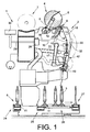
- Fig. 1 is a side view schematically a job 2 of a cheese-producing textile machine, in the embodiment, a so-called cross-winding machine 1, shown.
- spinning tows 3 produced on ring spinning machines and having relatively little yarn material are rewound to large-volume cheeses 5 on the work stations 2 of such automatic packages 1.
- the cheeses 5 are after their completion by means of a (not shown) automatically operating service unit, preferably a cheese changer, handed over to a machine-length cheese package transport means 7 and transported to a machine end side Spulenverladestation or the like.
- such automatic packages 1 also have a logistics device in the form of a cop and tube transport system 6.
- the spinning cops 3 or empty tubes run on transport plates 11.
- From the cop and sleeve transport system 6 are in the Fig. 1 only the Kopszu slaughterhouse 24, the reversibly driven storage section 25, one of the leading to the winding units 2 Cross transport lines 26 and the sleeve return path 27 shown.
- Each work station 2 of the automatic winder 1 has a control device, a so-called winding station computer 28, which is connected, inter alia, via a bus connection 29 to a central control unit 30 of the automatic package winder 1 and via control lines 15, 35 to the individual drives 14, 33 of the winding device 4. Furthermore, each of the jobs 2 has various other facilities necessary for the proper operation of the jobs 2.
- Such a winding device 4 has inter alia a coil frame 8, which, as in Fig.1 indicated, at least about a pivot axis 12 which is parallel to the axis of rotation of the cheese 5, is movably mounted.
- the coil frame 8 can also, what is also basically known and therefore not shown for reasons of clarity, to a further pivot axis which is orthogonal to the pivot axis 12, limited to be rotatably mounted. That is, the coil frame 8 is formed so that either cylindrical or conical cheeses can be wound on it.
- Fig. 1 in the coil frame 8 freely rotatably supported cross-wound bobbin 5 during the winding operation with its surface on a bobbin drive roller 9, which is acted upon by an electric motor 33 single motor.
- the electric motor 33 is connected via a control line 35 to the workstation computer 28.
- a thread traversing device 10 is provided for traversing the thread 16 during the winding process.
- Fadenchangier listening 10 preferably has a finger thread guide 13, which, acted upon by an electromagnetic, reversible single drive 14, traversing the thread 16 running on the cheese 5 at high speed between the end faces of the cheese 5.
- the yarn guide drive 14 is also connected via a control line 15 to the workstation computer 28 in connection.
- Such jobs 2 usually also have a thread connecting device 42, preferably a pneumatic splicing device, a gripper tube 43 for handling the lower thread and a suction nozzle 17, with which an accumulated on the cheese 5 top thread can be added and inserted into the thread connecting device 42.
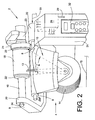
- the Fig. 2 shows the winding device 4 a job 2 in a perspective front view.
- each of these workstations 2 has a winding unit housing 31 equipped with an input device 32, which accommodates, inter alia, the control device of the workstation 2, preferably a so-called winding station computer 28.
- the winding device 4 of the job 2 is also set, which consists essentially of the creel 8 for holding the sleeve 18 of a cheese 5, the bobbin drive roller 9 for rotating the sleeve 18 and the cheese 5 and a Fadenchangier disturbing 10 for traversing on the cheese 5 accumulating thread 16 consists.
- the Fadenchangier gifted 10 has a finger thread guide 13, the electromagnetic single drive 14 is connected via a control line 15 to the winding station computer 28.
- the finger thread guide 13 is controlled via the winding station computer 28 controllable, that is, among other things, the thread laying speed and the thread laying area are precisely adjustable.
- the bobbin drive roller 9 also has an electromagnetic single drive 33, which in turn is connected via the control line 35 to the winding station computer 28.
- the coil frame 8 which, as already explained above, is rotatably mounted limitedly limited at least about a pivot axis 12, has two coil frame arms 20, 21, which in turn are each equipped with a rotatably mounted sleeve receiving plate 22.
- the arranged on the Spulenrahmenarm 21 sleeve receiving plate 22 which is operatively connected to a reel brake 23 is mounted axially displaceable. That is, this arranged on the Spulenrahmenarm 21 sleeve receiving plate 22 can, if necessary, in particular for inserting a cheese reel sleeve 18 or for removing a cross-wound bobbin 5, slightly withdrawn.
- the freely rotatably mounted sleeve receiving plate 22 on the coil frame arm 20 is arranged easily replaceable.
- this sleeve receiving plate 22 may, if necessary, for example, after loosening a bolt 34, easily removed from its storage on the Spulenrahmenarm 20 and replaced by an adapter 19, which in turn has a corresponding sleeve receiving plate 22.
- a suitable cheese coil 18 and an associated adapter 19 is selected.
- the cross coil sleeve 18 corresponding to the desired cross coil format is inserted into the coil frame 8, fixed by means of the associated adapter 19 between the coil frame arms 20, 21 and the corresponding sleeve receiving plates 22 of the coil frame 8 and selected on the input device 32, the desired cross coil format.
- the winding station computer 28 connected to the input device 32 controls the drive 14 of the yarn finger guide 13 such that the yarn 16 is always wound in the region in which the inserted cheese package 18 is positioned. That is, the finger thread guide 13 traverses the run-up thread 16 in the in Fig. 2 marked with ⁇ angle range, which leads, for example, to produce a 2 "wide cheese 5.
Landscapes
- Winding Filamentary Materials (AREA)
Claims (8)
- Dispositif de bobinage (4) pour un poste de travail (2) d'une machine textile (1) fabriquant des bobines croisées, avec un porte-bobine (8) pour maintenir un tube (18) de bobine croisée monté à rotation, un organe (9, 33) pour faire tourner le tube (18) de bobine croisée ou encore une bobine croisée (5), ainsi qu'un organe va-et-vient (10), pouvant être entraîné séparément et destiné à déplacer en va-et-vient un fil (16) montant sur la bobine croisée (5), organe qui est conçu de telle sorte que la course de va-et-vient peut être sélectivement modifiée, permettant ainsi de fabriquer différents formats de bobines croisées, caractérisé en ce que le dispositif de bobinage (4) présente un porte-bobine (8) qui, en l'équipant d'adaptateurs (19) de différentes longueurs, peut être modifié d'une manière simple de telle sorte que des tubes (18) de bobine croisée de différentes longueurs et de différents formats de tube peuvent être fixés en position entre les bras (20, 21) du porte-bobine (8).
- Dispositif de bobinage selon la revendication 1, caractérisé en ce que l'adaptateur respectif (19) peut être fixé à la place d'un plateau récepteur de bobine (22) sur un des bras (20, 21) du porte-bobine (8).
- Dispositif de bobinage selon les revendications 1 et 2, caractérisé en ce que l'adaptateur (19) est respectivement réalisé sous forme d'élément du genre tube, et est équipé d'un plateau récepteur de bobine (22) disposé à une extrémité et monté à rotation.
- Dispositif de bobinage selon la revendication 3, caractérisé en ce que l'adaptateur (19) peut être équipé de plateaux récepteurs de bobine (22) adaptés aux différents formats de tube.
- Dispositif de bobinage selon la revendication 2, caractérisé en ce que l'adaptateur (19) est respectivement disposé sur le bras de porte-bobine qui fait face au bras de porte-bobine qui est équipé d'un frein de bobine (23).
- Dispositif de bobinage selon la revendication 1, caractérisé en ce que l'organe va-et-vient (10) présente un doigt guide-fil (13) et est raccordé par son entraînement (14) à un organe de commande (28) du poste de travail concerné (2).
- Dispositif de bobinage selon la revendication 1, caractérisé en ce qu'il est prévu un cylindre d'entraînement de bobine (9) qui peut être entraîné par un moteur individuel et qui fait tourner la bobine croisée (5) par engagement par friction pendant le processus de bobinage.
- Dispositif de bobinage selon la revendication 1, caractérisé en ce que le dispositif de bobinage (4) présente un porte-bobine (8) qui présente, en plus d'un axe de pivotement (12) s'étendant parallèlement à l'axe de rotation de la bobine croisée (5), un autre axe de pivotement s'étendant orthogonalement à cet axe de pivotement (12).
Applications Claiming Priority (1)
| Application Number | Priority Date | Filing Date | Title |
|---|---|---|---|
| DE102007018660A DE102007018660A1 (de) | 2007-04-20 | 2007-04-20 | Spulvorrichtung für eine Arbeitsstelle einer Kreuzspulen herstellenden Textilmaschine |
Related Parent Applications (1)
| Application Number | Title | Priority Date | Filing Date |
|---|---|---|---|
| DE102007018660 Previously-Filed-Application | 2007-04-20 |
Publications (3)
| Publication Number | Publication Date |
|---|---|
| EP1982943A2 EP1982943A2 (fr) | 2008-10-22 |
| EP1982943A3 EP1982943A3 (fr) | 2009-11-04 |
| EP1982943B1 true EP1982943B1 (fr) | 2011-06-08 |
Family
ID=39493231
Family Applications (1)
| Application Number | Title | Priority Date | Filing Date |
|---|---|---|---|
| EP20080006782 Active EP1982943B1 (fr) | 2007-04-20 | 2008-04-03 | Dispositif de bobinage pour un poste de travail d'une machine textile fabriquant des bobines |
Country Status (2)
| Country | Link |
|---|---|
| EP (1) | EP1982943B1 (fr) |
| DE (1) | DE102007018660A1 (fr) |
Families Citing this family (1)
| Publication number | Priority date | Publication date | Assignee | Title |
|---|---|---|---|---|
| DE102021129226A1 (de) | 2021-11-10 | 2023-05-11 | Saurer Spinning Solutions Gmbh & Co. Kg | Fadenleiteinrichtung für eine Spulvorrichtung |
Family Cites Families (14)
| Publication number | Priority date | Publication date | Assignee | Title |
|---|---|---|---|---|
| DE7217902U (de) * | 1972-08-03 | Palitex Project Co Gmbh | Spulenhalter | |
| LU42729A1 (fr) * | 1962-11-22 | 1964-05-22 | ||
| GB1351934A (en) * | 1969-12-02 | 1974-05-01 | Ronfred Eng Co Ltd | Tube adapter for use with textile yarn processing machines |
| DE3628735A1 (de) | 1986-08-23 | 1988-02-25 | Hacoba Textilmaschinen | Fadenfuehrungsvorrichtung fuer spulmaschinen |
| JP2530165Y2 (ja) * | 1990-06-29 | 1997-03-26 | 株式会社ミタニ | ボビン巻取り装置のボビン保持機構 |
| DE9016205U1 (de) * | 1990-11-29 | 1991-02-14 | FAG Kugelfischer Georg Schäfer KGaA, 8720 Schweinfurt | Spulenhalterung für hochtourige Textilspindeln |
| US5305962A (en) | 1991-06-19 | 1994-04-26 | Murata Kikai Kabushiki Kaisha | Yarn winding apparatus and method |
| JPH08104470A (ja) * | 1994-10-05 | 1996-04-23 | Abansu Techno Kk | ボビン |
| GB9510825D0 (en) * | 1995-05-23 | 1995-07-19 | Rieter Scragg Ltd | Package support device |
| EP0712802B1 (fr) * | 1995-08-16 | 2000-03-22 | TEMCO Textilmaschinenkomponenten GmbH | Adaptateur de bobine |
| JPH0986794A (ja) * | 1995-09-22 | 1997-03-31 | Hitachi Cable Ltd | ボビン装着構造 |
| DE19858548A1 (de) | 1998-12-18 | 2000-06-21 | Schlafhorst & Co W | Fadenführer zum traversierenden Zuführen eines Fadens zu einer rotierend angetriebenen Auflaufspule |
| DE19908093A1 (de) * | 1999-02-25 | 2000-08-31 | Schlafhorst & Co W | Spulvorrichtung für eine Kreuzspulen herstellende Textilmaschine |
| EP1126058A3 (fr) | 2000-02-17 | 2002-11-27 | Schärer Schweiter Mettler AG | Dispositif d'entraínement d'organes tournant dans une machine à filer à bout libre |
-
2007
- 2007-04-20 DE DE102007018660A patent/DE102007018660A1/de not_active Withdrawn
-
2008
- 2008-04-03 EP EP20080006782 patent/EP1982943B1/fr active Active
Also Published As
| Publication number | Publication date |
|---|---|
| EP1982943A3 (fr) | 2009-11-04 |
| DE102007018660A1 (de) | 2008-10-23 |
| EP1982943A2 (fr) | 2008-10-22 |
Similar Documents
| Publication | Publication Date | Title |
|---|---|---|
| EP2029465B1 (fr) | Procédé de fonctionnement du poste de travail d'une machine textile produisant des bobines croisées | |
| EP1807335B2 (fr) | Procede et dispositif pour faire fonctionner un poste de travail de machine textile produisant des bobines croisees | |
| DE102009009971B4 (de) | Verfahren und Vorrichtung zum Betreiben einer Arbeitsstelle einer Kreuzspulen herstellenden Textilmaschine sowie Arbeitsstelle zur Durchführung des Verfahrens | |
| EP2740699B1 (fr) | Dispositif de bobinage pour un poste de travail d'une machine textile fabriquant des bobines | |
| DE102016119542A1 (de) | Fadenspleißvorrichtung für eine Arbeitsstelle einer Kreuzspulen herstellenden Textilmaschine | |
| DE102012016853A1 (de) | Verfahren zum Verbinden eines Ober- und Unterfadens an einer Arbeitsstelle einer Spulmaschine und Arbeitsstelle einer Spulmaschine | |
| DE102016115732A1 (de) | Fadenspleißvorrichtung für eine Arbeitsstelle einer Kreuzspulen herstellenden Textilmaschine | |
| DE102017114707A1 (de) | Fadenspleißvorrichtung zum pneumatischen Verbinden von Fadenenden | |
| DE102008015907A1 (de) | Verfahren zur Steuerung einer von einem einzelmotorischen Antrieb angetriebenen Changiereinrichtung an einer Vorrichtung zum Wickeln konischer Kreuzspulen sowie eine Kreuzspulen herstellende Textilmaschine | |
| DE102012016854A1 (de) | Verfahren zum Verbinden eines Ober- und Unterfadens an einer Arbeitsstelle einer Spulmaschine und Arbeitsstelle einer Spulmaschine | |
| DE102011111033A1 (de) | Fadenspleißvorrichtung für eine Kreuzspulen herstellende Textilmaschine | |
| DE102006006390A1 (de) | Fadenspleißvorrichtung für eine Kreuzspulen herstellende Textilmaschine | |
| EP2279976B1 (fr) | Procédé destiné au fonctionnement de postes de travail d'une machine textile produisant des bobines croisées | |
| EP2388224A2 (fr) | Agrégat de commande | |
| EP1127831B1 (fr) | Dispositif de mise en service d'un poste de travail d'une machine textile pour la fabrication de bobines à spires croisées | |
| EP1971545B1 (fr) | Dispositif d'epissage de fils pour machine textile qui forme des bobines croisees | |
| EP1828040B1 (fr) | Poste de travail de bobineuse | |
| EP1728748A1 (fr) | Dispositif de va-et-vient de fil pour un bobinoir d'une machine textile produisant des bobines croisées | |
| DE102017102438A1 (de) | Fadenspleißvorrichtung für eine Arbeitsstelle einer Kreuzspulen herstellenden Textilmaschine | |
| EP1982943B1 (fr) | Dispositif de bobinage pour un poste de travail d'une machine textile fabriquant des bobines | |
| DE10239334A1 (de) | Fadenspulmaschine mit einem Spannungsdetektor | |
| EP1783082B1 (fr) | Procédé pour rebobiner des bobines de teintures sur des bobines croisées | |
| DE4017303A1 (de) | Verfahren zur herstellung von kreuzspulen mit unterschiedlicher garnlaenge | |
| DE102012002986A1 (de) | Arbeitsstelle einer Kreuzspulen herstellenden Textilmaschine | |
| EP1302428A1 (fr) | Dispositif d'épissure de fils |
Legal Events
| Date | Code | Title | Description |
|---|---|---|---|
| PUAI | Public reference made under article 153(3) epc to a published international application that has entered the european phase |
Free format text: ORIGINAL CODE: 0009012 |
|
| AK | Designated contracting states |
Kind code of ref document: A2 Designated state(s): AT BE BG CH CY CZ DE DK EE ES FI FR GB GR HR HU IE IS IT LI LT LU LV MC MT NL NO PL PT RO SE SI SK TR |
|
| AX | Request for extension of the european patent |
Extension state: AL BA MK RS |
|
| PUAL | Search report despatched |
Free format text: ORIGINAL CODE: 0009013 |
|
| AK | Designated contracting states |
Kind code of ref document: A3 Designated state(s): AT BE BG CH CY CZ DE DK EE ES FI FR GB GR HR HU IE IS IT LI LT LU LV MC MT NL NO PL PT RO SE SI SK TR |
|
| AX | Request for extension of the european patent |
Extension state: AL BA MK RS |
|
| 17P | Request for examination filed |
Effective date: 20100504 |
|
| AKX | Designation fees paid |
Designated state(s): CH DE IT LI TR |
|
| 17Q | First examination report despatched |
Effective date: 20100629 |
|
| GRAP | Despatch of communication of intention to grant a patent |
Free format text: ORIGINAL CODE: EPIDOSNIGR1 |
|
| RIC1 | Information provided on ipc code assigned before grant |
Ipc: B65H 54/553 20060101AFI20110110BHEP Ipc: B65H 75/18 20060101ALI20110110BHEP |
|
| GRAS | Grant fee paid |
Free format text: ORIGINAL CODE: EPIDOSNIGR3 |
|
| GRAA | (expected) grant |
Free format text: ORIGINAL CODE: 0009210 |
|
| AK | Designated contracting states |
Kind code of ref document: B1 Designated state(s): CH DE IT LI TR |
|
| REG | Reference to a national code |
Ref country code: CH Ref legal event code: EP |
|
| REG | Reference to a national code |
Ref country code: DE Ref legal event code: R096 Ref document number: 502008003762 Country of ref document: DE Effective date: 20110721 |
|
| PLBE | No opposition filed within time limit |
Free format text: ORIGINAL CODE: 0009261 |
|
| STAA | Information on the status of an ep patent application or granted ep patent |
Free format text: STATUS: NO OPPOSITION FILED WITHIN TIME LIMIT |
|
| 26N | No opposition filed |
Effective date: 20120309 |
|
| REG | Reference to a national code |
Ref country code: DE Ref legal event code: R097 Ref document number: 502008003762 Country of ref document: DE Effective date: 20120309 |
|
| REG | Reference to a national code |
Ref country code: DE Ref legal event code: R081 Ref document number: 502008003762 Country of ref document: DE Owner name: SAURER GERMANY GMBH & CO. KG, DE Free format text: FORMER OWNER: OERLIKON TEXTILE GMBH & CO. KG, 42897 REMSCHEID, DE Effective date: 20130918 |
|
| REG | Reference to a national code |
Ref country code: CH Ref legal event code: NV Representative=s name: SCHMAUDER AND PARTNER AG PATENT- UND MARKENANW, CH Ref country code: CH Ref legal event code: PUE Owner name: SAURER GERMANY GMBH AND CO. KG, DE Free format text: FORMER OWNER: OERLIKON TEXTILE GMBH AND CO. KG, DE |
|
| REG | Reference to a national code |
Ref country code: CH Ref legal event code: PCOW Free format text: NEW ADDRESS: LEVERKUSER STRASSE 65, 42897 REMSCHEID (DE) |
|
| PGFP | Annual fee paid to national office [announced via postgrant information from national office to epo] |
Ref country code: DE Payment date: 20150506 Year of fee payment: 8 |
|
| REG | Reference to a national code |
Ref country code: DE Ref legal event code: R119 Ref document number: 502008003762 Country of ref document: DE |
|
| PG25 | Lapsed in a contracting state [announced via postgrant information from national office to epo] |
Ref country code: DE Free format text: LAPSE BECAUSE OF NON-PAYMENT OF DUE FEES Effective date: 20161101 |
|
| P01 | Opt-out of the competence of the unified patent court (upc) registered |
Effective date: 20230519 |
|
| PGFP | Annual fee paid to national office [announced via postgrant information from national office to epo] |
Ref country code: IT Payment date: 20250424 Year of fee payment: 18 |
|
| PGFP | Annual fee paid to national office [announced via postgrant information from national office to epo] |
Ref country code: CH Payment date: 20250501 Year of fee payment: 18 |
|
| PGFP | Annual fee paid to national office [announced via postgrant information from national office to epo] |
Ref country code: TR Payment date: 20260331 Year of fee payment: 19 |