EP1982943B1 - Spooling device for a workstation of a textile machine for creating cross-wound spools - Google Patents
Spooling device for a workstation of a textile machine for creating cross-wound spools Download PDFInfo
- Publication number
- EP1982943B1 EP1982943B1 EP20080006782 EP08006782A EP1982943B1 EP 1982943 B1 EP1982943 B1 EP 1982943B1 EP 20080006782 EP20080006782 EP 20080006782 EP 08006782 A EP08006782 A EP 08006782A EP 1982943 B1 EP1982943 B1 EP 1982943B1
- Authority
- EP
- European Patent Office
- Prior art keywords
- cross
- winding device
- creel
- winding
- bobbin
- Prior art date
- Legal status (The legal status is an assumption and is not a legal conclusion. Google has not performed a legal analysis and makes no representation as to the accuracy of the status listed.)
- Active
Links
Images
Classifications
-
- B—PERFORMING OPERATIONS; TRANSPORTING
- B65—CONVEYING; PACKING; STORING; HANDLING THIN OR FILAMENTARY MATERIAL
- B65H—HANDLING THIN OR FILAMENTARY MATERIAL, e.g. SHEETS, WEBS, CABLES
- B65H54/00—Winding, coiling, or depositing filamentary material
- B65H54/02—Winding and traversing material on to reels, bobbins, tubes, or like package cores or formers
- B65H54/40—Arrangements for rotating packages
- B65H54/54—Arrangements for supporting cores or formers at winding stations; Securing cores or formers to driving members
- B65H54/553—Both-ends supporting arrangements
-
- B—PERFORMING OPERATIONS; TRANSPORTING
- B65—CONVEYING; PACKING; STORING; HANDLING THIN OR FILAMENTARY MATERIAL
- B65H—HANDLING THIN OR FILAMENTARY MATERIAL, e.g. SHEETS, WEBS, CABLES
- B65H75/00—Storing webs, tapes, or filamentary material, e.g. on reels
- B65H75/02—Cores, formers, supports, or holders for coiled, wound, or folded material, e.g. reels, spindles, bobbins, cop tubes, cans, mandrels or chucks
- B65H75/18—Constructional details
- B65H75/185—End caps, plugs or adapters
-
- B—PERFORMING OPERATIONS; TRANSPORTING
- B65—CONVEYING; PACKING; STORING; HANDLING THIN OR FILAMENTARY MATERIAL
- B65H—HANDLING THIN OR FILAMENTARY MATERIAL, e.g. SHEETS, WEBS, CABLES
- B65H2701/00—Handled material; Storage means
- B65H2701/30—Handled filamentary material
- B65H2701/31—Textiles threads or artificial strands of filaments
Definitions
- the invention relates to a winding device for a workstation of a cross-wound textile machine according to the preamble of claim 1.
- Such thread guide drums traverse the incoming thread during the winding process and at the same time drive the cross-wound bobbin via frictional engagement.
- winding devices are known in which the drive for the cheese and the drive for the Fadenchangier interests are separated. That is, in the manufacture of a cross winding in the winding type precision or step precision winding, the cheese is driven by a reel drive, while the incoming yarn is laid by an additional, separately driven Fadenchangier immunity.
- Fadenchangier drivenen having either a yarn guide, which is connected for example via a traction means with a reversible single drive or Fadenchangier drivingen having a finger-like thread laying lever, which is defined about a substantially perpendicular to the cheese axis arranged axis pivotally mounted and defined over a certain angular range a reversible electromagnetic drive is connected.
- such a winding device for a job of a cheeses described textile machine in which the Fadenchangier worn is designed as a finger thread guide.
- the single electromagnetic drive of the finger thread guide is also connected to a control device, the angle and the time depending on the current strength and the current direction according to a predetermined program so pretending that adjusts the Traversierbreite the finger thread guide a certain installation angle of the thread.
- winding devices as by the DE 198 58 548 A1
- high traverse speeds are known to be realized during the winding process, it is disadvantageous in such winding devices that they are generally designed for a specific cross-coil format, for example for 6 "wide coils. That is, with these known winding devices only cross-wound bobbins can be spooled with a certain width.
- the Fadenchangier drives are designed so that they can be reacted very universally to a wide variety of requirements of a winding device. That is, with such winding devices, it is in principle possible to wind cross-wound bobbins with different formats and widths, but even with these winder devices when changing the sleeve format, especially when sleeves are to be used with a different length, always a relatively complex adaptation of Winding device, usually a change of the coil frame, necessary.
- winding devices that work with a thread guide drum, with respect to the winding of different width cheeses, especially if it is also the case format to be changed, only partially suitable.
- a winding device whose yarn guide drum can be limited to a shortened coil width by blocking certain areas of the yarn guide groove.
- a special traversing device can be positioned in the region of a arranged in front of the thread guide drum thread guide in this known winding device.
- Winding devices which each have a drive in the region of the spool axis of the cross-wound bobbin, by means of which the cross-wound bobbin can be driven directly via the cheese bobbin case and thereby friction-entrains a pressure roller.
- the traversing of the running thread is carried out in these winding devices in each case by a spaced apart from the cheese, single motor driven yarn guide drum.
- a stroke limiting device mounted axially displaceably in the direction of the spool axis is also arranged, by means of which the winding width of the cross-wound bobbin held in the bobbin frame and the position of the traversing triangle of the thread can be adjusted during emergence onto the cross-wound bobbin.
- a winding device according to the preamble of claim 1 is also known from DE 199 08 093 A1 known.
- the present invention seeks to develop a winding device, which makes it possible to wind either different cross coil formats.
- the hitherto necessary, costly conversion measures in the region of the coil frame are to be minimized when changing the format of the cheese coil used.
- the winding device according to the invention which has a creel, which is so easily modified by equipping with adapters of different lengths that Cheese bobbins different length and different sleeve size between the coil frame arms of the creel can be fixed, has the advantage that in case of need the cross-wound bobbin required in a simple way quickly and completely easily in the creel of the work can be fixed and can be wound properly by the Fadenchangier worn immediately. That is, in the winding device according to the invention, only a matching adapter needs to be inserted into the bobbin frame when changing the sleeve format, and the thread switching device has to be set to the new cross bobbin format by software. Any further conversion measures, which are usually cost and time consuming, need not be made in the field of winding device.
- the respective adapter is fixed instead of a sleeve receiving plate on one of the coil frame arms of the coil frame. That is, after loosening a bolt, the rotatably mounted sleeve receiving plate can be removed and replaced by a matching adapter, which in turn is secured by the bolt.
- the adapter is preferably formed as a tubular member and either already equipped with a rotatably mounted end-mounted sleeve receiving plate or the adapter is equipped with the previously removed or with a new sleeve receiving plate.
- the sleeve receiving plate of the adapter summarizes in the installed state in one of the end faces of a cheese package, which rests with its opposite end face on a rotatable sleeve receiving plate of the second creel and thereby securely positioned.
- the adapter is also, as described in claim 4, each equipped with a matching sleeve receiving plate. That is, the adapter has a sleeve receiving plate, which is designed specifically for the sleeve format to be fixed and therefore ensures proper retention of the cheese to be produced.
- the adapter is advantageous to arrange the adapter on the Spulenrahmenarm, which has no spool brake. In this way, it is ensured that the brake torque applied by the spool brake during braking of the spool brake is transmitted directly to the cheese package without the intervention of an adapter, which increases the risk of additional slippage when the cheese is being slowed down between the sleeve receiving plate of the adapter and the cheese package comes, clearly minimized.
- the thread-switching device is equipped with a finger thread guide and connected with its drive to a control device of the workstation, preferably the so-called winding station computer.
- a control device of the workstation preferably the so-called winding station computer.
- each of the numerous jobs of the cheese-producing textile machine as described in claim 7, a winding device with a motor driven single-motor reel drive roller, which rotates the cheese during the winding process via frictional engagement.
- a single-motor driven bobbin drive roller represents a largely independent of the format of the cheese to be driven, in textile machinery for a long time proven drive means that ensures a safe drive each cheese during the entire winding process.
- the winding device is equipped in an advantageous embodiment with a coil frame, which has, in addition to a pivot axis which is parallel to the axis of rotation of the cheese, a further pivot axis which is arranged orthogonal to the axis of rotation of the package held in the coil cheese.
- the creel can be used if necessary both for the production of cylindrical cheeses and for the production of conical cheeses, the conical cheeses can have the different, common inclination angle.
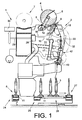
- Fig. 1 is a side view schematically a job 2 of a cheese-producing textile machine, in the embodiment, a so-called cross-winding machine 1, shown.
- spinning tows 3 produced on ring spinning machines and having relatively little yarn material are rewound to large-volume cheeses 5 on the work stations 2 of such automatic packages 1.
- the cheeses 5 are after their completion by means of a (not shown) automatically operating service unit, preferably a cheese changer, handed over to a machine-length cheese package transport means 7 and transported to a machine end side Spulenverladestation or the like.
- such automatic packages 1 also have a logistics device in the form of a cop and tube transport system 6.
- the spinning cops 3 or empty tubes run on transport plates 11.
- From the cop and sleeve transport system 6 are in the Fig. 1 only the Kopszu slaughterhouse 24, the reversibly driven storage section 25, one of the leading to the winding units 2 Cross transport lines 26 and the sleeve return path 27 shown.
- Each work station 2 of the automatic winder 1 has a control device, a so-called winding station computer 28, which is connected, inter alia, via a bus connection 29 to a central control unit 30 of the automatic package winder 1 and via control lines 15, 35 to the individual drives 14, 33 of the winding device 4. Furthermore, each of the jobs 2 has various other facilities necessary for the proper operation of the jobs 2.
- Such a winding device 4 has inter alia a coil frame 8, which, as in Fig.1 indicated, at least about a pivot axis 12 which is parallel to the axis of rotation of the cheese 5, is movably mounted.
- the coil frame 8 can also, what is also basically known and therefore not shown for reasons of clarity, to a further pivot axis which is orthogonal to the pivot axis 12, limited to be rotatably mounted. That is, the coil frame 8 is formed so that either cylindrical or conical cheeses can be wound on it.
- Fig. 1 in the coil frame 8 freely rotatably supported cross-wound bobbin 5 during the winding operation with its surface on a bobbin drive roller 9, which is acted upon by an electric motor 33 single motor.
- the electric motor 33 is connected via a control line 35 to the workstation computer 28.
- a thread traversing device 10 is provided for traversing the thread 16 during the winding process.
- Fadenchangier listening 10 preferably has a finger thread guide 13, which, acted upon by an electromagnetic, reversible single drive 14, traversing the thread 16 running on the cheese 5 at high speed between the end faces of the cheese 5.
- the yarn guide drive 14 is also connected via a control line 15 to the workstation computer 28 in connection.
- Such jobs 2 usually also have a thread connecting device 42, preferably a pneumatic splicing device, a gripper tube 43 for handling the lower thread and a suction nozzle 17, with which an accumulated on the cheese 5 top thread can be added and inserted into the thread connecting device 42.
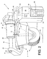
- the Fig. 2 shows the winding device 4 a job 2 in a perspective front view.
- each of these workstations 2 has a winding unit housing 31 equipped with an input device 32, which accommodates, inter alia, the control device of the workstation 2, preferably a so-called winding station computer 28.
- the winding device 4 of the job 2 is also set, which consists essentially of the creel 8 for holding the sleeve 18 of a cheese 5, the bobbin drive roller 9 for rotating the sleeve 18 and the cheese 5 and a Fadenchangier disturbing 10 for traversing on the cheese 5 accumulating thread 16 consists.
- the Fadenchangier gifted 10 has a finger thread guide 13, the electromagnetic single drive 14 is connected via a control line 15 to the winding station computer 28.
- the finger thread guide 13 is controlled via the winding station computer 28 controllable, that is, among other things, the thread laying speed and the thread laying area are precisely adjustable.
- the bobbin drive roller 9 also has an electromagnetic single drive 33, which in turn is connected via the control line 35 to the winding station computer 28.
- the coil frame 8 which, as already explained above, is rotatably mounted limitedly limited at least about a pivot axis 12, has two coil frame arms 20, 21, which in turn are each equipped with a rotatably mounted sleeve receiving plate 22.
- the arranged on the Spulenrahmenarm 21 sleeve receiving plate 22 which is operatively connected to a reel brake 23 is mounted axially displaceable. That is, this arranged on the Spulenrahmenarm 21 sleeve receiving plate 22 can, if necessary, in particular for inserting a cheese reel sleeve 18 or for removing a cross-wound bobbin 5, slightly withdrawn.
- the freely rotatably mounted sleeve receiving plate 22 on the coil frame arm 20 is arranged easily replaceable.
- this sleeve receiving plate 22 may, if necessary, for example, after loosening a bolt 34, easily removed from its storage on the Spulenrahmenarm 20 and replaced by an adapter 19, which in turn has a corresponding sleeve receiving plate 22.
- a suitable cheese coil 18 and an associated adapter 19 is selected.
- the cross coil sleeve 18 corresponding to the desired cross coil format is inserted into the coil frame 8, fixed by means of the associated adapter 19 between the coil frame arms 20, 21 and the corresponding sleeve receiving plates 22 of the coil frame 8 and selected on the input device 32, the desired cross coil format.
- the winding station computer 28 connected to the input device 32 controls the drive 14 of the yarn finger guide 13 such that the yarn 16 is always wound in the region in which the inserted cheese package 18 is positioned. That is, the finger thread guide 13 traverses the run-up thread 16 in the in Fig. 2 marked with ⁇ angle range, which leads, for example, to produce a 2 "wide cheese 5.
Landscapes
- Winding Filamentary Materials (AREA)
Description
Die Erfindung betrifft eine Spulvorrichtung für eine Arbeitsstelle einer Kreuzspulen herstellenden Textilmaschine gemäß dem Oberbegriff des Anspruches 1.The invention relates to a winding device for a workstation of a cross-wound textile machine according to the preamble of
Um eine Textilspule herzustellen, ist es bekanntlich erforderlich, dass die betreffende Textilspule einerseits um ihre Spulenachse rotiert und andererseits der auf die Spule auflaufende Faden längs der Spulenachse traversiert wird.
Durch relativ schnelles Traversieren des Fadens kann dabei eine so genannte Kreuzbewicklung erstellt werden.
Bei derartigen Kreuzspulen, die sich nicht nur durch einen verhältnismäßig stabilen Spulenkörper, sondern auch durch ein gutes Ablaufverhalten auszeichnen, wird nicht nur hinsichtlich ihrer Wicklungsart unterschieden, beispielsweise "Wilde Wicklung", "Präzisionswicklung" oder "Stufen-Präzisionswicklung", sondern auch bezüglich verschiedener Kreuzspulenformate.
Man unterscheidet beispielsweise zwischen zylindrischen und konischen Spulen sowie zwischen Spulen unterschiedlicher Breite. Im Zusammenhang mit Kreuzspulen herstellenden Textilmaschinen sind beispielsweise 4", 5", 6" etc. breite Spulen üblich. Abhängig vom Kreuzspulenformat kommen dabei unterschiedliche Hülsenformate zum Einsatz, die sich unter anderem auch bezüglich ihrer Länge unterscheiden.In order to produce a textile bobbin, it is known that it is necessary for the textile bobbin in question to be rotated on the one hand around its bobbin axis and, on the other hand, for the thread running onto the bobbin to be traversed along the bobbin axis.
By relatively fast traversing of the thread, a so-called Kreuzbewicklung can be created.
In such cheeses, which are distinguished not only by a relatively stable bobbin, but also by a good flow behavior, not only in terms of their winding type, such as "wild winding", "precision winding" or "step precision winding", but also with respect to different cheeses formats.
For example, a distinction is made between cylindrical and conical coils and between coils of different widths. In the context of textile machines producing cross-wound bobbins, for example, 4 ", 5", 6 ", etc. wide bobbins are common Depending on the cross bobbin format, different bobbin formats are used, which differ, inter alia, also with respect to their length.
Insbesondere bei der Herstellung von Kreuzspulen mit der Wicklungsart "Wilde Wicklung" sind Spulvorrichtungen weit verbreitet, die mit so genannten Fadenführungstrommeln arbeiten.In particular, in the production of cheeses with the winding type "wild winding" winding devices are widely used, which operate with so-called thread guide drums.
Solche Fadenführungstrommeln traversieren während des Spulprozesses den auflaufenden Faden und treiben gleichzeitig auch die Kreuzspule über Reibschluss an.Such thread guide drums traverse the incoming thread during the winding process and at the same time drive the cross-wound bobbin via frictional engagement.
Des Weiteren sind, speziell im Zusammenhang mit der Herstellung von Kreuzspulen mit Präzisions- oder Stufen-Präzisionswicklung, auch Spulvorrichtungen bekannt, bei denen der Antrieb für die Kreuzspule und der Antrieb für die Fadenchangiereinrichtung getrennt sind.
Das heißt, bei der Herstellung einer Kreuzspule in der Wicklungsart Präzisions- oder Stufen-Präzisionswicklung wird die Kreuzspule durch einen Spulenantrieb angetrieben, während der auflaufende Faden durch eine zusätzliche, separat angetriebene Fadenchangiereinrichtung verlegt wird.Furthermore, also in connection with the production of cheeses with precision or step precision winding, winding devices are known in which the drive for the cheese and the drive for the Fadenchangiereinrichtung are separated.
That is, in the manufacture of a cross winding in the winding type precision or step precision winding, the cheese is driven by a reel drive, while the incoming yarn is laid by an additional, separately driven Fadenchangiereinrichtung.
Als sehr geeignet für eine schnelle und positionsgenaue Fadenchangierung haben sich dabei Einrichtungen erwiesen, die über einen parallel zur Rotationsachse der Kreuzspule verschiebbaren Fadenführer verfügen sowie Fadenchangiereinrichtungen, die mit einem so genannten Fingerfadenführer arbeiten.
Das heißt, Fadenchangiereinrichtungen, die entweder einen Fadenführer aufweisen, der z.B. über ein Zugmittel mit einem reversierbaren Einzelantrieb verbunden ist oder Fadenchangiereinrichtungen, die einen fingerartigen Fadenverlegehebel besitzen, der um eine im wesentlichen senkrecht zur Kreuzspulenachse angeordnete Achse über einen bestimmten Winkelbereich definiert schwenkbar gelagert und an einen reversierbaren elektromagnetischen Antrieb angeschlossen ist.Devices which have a thread guide which can be displaced parallel to the axis of rotation of the cross-wound bobbin and thread-changing devices which operate with a so-called finger thread guide have proven to be very suitable for a fast and positionally precise threading.
That is, Fadenchangiereinrichtungen having either a yarn guide, which is connected for example via a traction means with a reversible single drive or Fadenchangiereinrichtungen having a finger-like thread laying lever, which is defined about a substantially perpendicular to the cheese axis arranged axis pivotally mounted and defined over a certain angular range a reversible electromagnetic drive is connected.
In der
Mit Spulvorrichtungen, wie sie durch die
Das heißt, mit diesen bekannten Spulvorrichtungen können stets nur Kreuzspulen mit einer bestimmten Breite gespult werden.In the
With winding devices, as by the
That is, with these known winding devices only cross-wound bobbins can be spooled with a certain width.
In der
Das heißt, mit solchen Spulvorrichtungen ist es grundsätzlich zwar möglich, Kreuzspulen mit unterschiedlichen Formaten und Breiten zu spulen, allerdings ist auch bei diesen Spulvorrichtungen bei einem Wechsel des Hülsenformats, insbesondere wenn Hülsen mit einer anderen Länge eingesetzt werden sollen, stets eine relativ aufwendige Anpassung der Spulvorrichtung, in der Regel ein Wechsel des Spulenrahmens, notwendig.In the
That is, with such winding devices, it is in principle possible to wind cross-wound bobbins with different formats and widths, but even with these winder devices when changing the sleeve format, especially when sleeves are to be used with a different length, always a relatively complex adaptation of Winding device, usually a change of the coil frame, necessary.
Auch Spulvorrichtungen, die mit einer Fadenführungstrommel arbeiten, sind bezüglich des Spulens von unterschiedlich breiten Kreuzspulen, insbesondere wenn dabei auch das Hülsenformat gewechselt werden soll, nur bedingt geeignet.Also, winding devices that work with a thread guide drum, with respect to the winding of different width cheeses, especially if it is also the case format to be changed, only partially suitable.
Bei einem Wechsel des Hülsenformats ist auch bei solchen Spulvorrichtungen in der Regel neben einem Wechsel der Fadenführungstrommel auch ein Wechsel des Spulenrahmens notwendig.In a change of the sleeve size, a change of the coil frame is also necessary in such winder usually in addition to a change of the thread guide drum.
In der
Zur Unterstützung dieser Hubbegrenzung bei der Fadenverlegung ist bei dieser bekannten Spulvorrichtung außerdem im Bereich einer vor der Fadenführungstrommel angeordneten Fadenführung eine spezielle Changierbegrenzungseinrichtung positionierbar. Mit der Spulvorrichtung gemäß
To support this stroke limitation in the thread laying is also a special traversing device can be positioned in the region of a arranged in front of the thread guide drum thread guide in this known winding device. With the winding device according to
Des Weiteren sind durch die
Die Changierung des auflaufenden Fadens erfolgt bei diesen Spulvorrichtungen jeweils durch eine beabstandet zur Kreuzspule angeordnete, einzelmotorisch angetriebene Fadenführungstrommel. Im Bereich der Fadenführungstrommel ist dabei außerdem eine in Richtung der Spulenachse axial verschiebbar gelagerte Hubbegrenzungseinrichtung angeordnet, mittels derer die Bewicklungsbreite der im Spulenrahmen gehaltenen Kreuzspule sowie die Lage des Changierdreiecks des Fadens beim Auflaufen auf die Kreuzspule eingestellt werden kann.Furthermore, by the
The traversing of the running thread is carried out in these winding devices in each case by a spaced apart from the cheese, single motor driven yarn guide drum. In the area of the thread guide drum, a stroke limiting device mounted axially displaceably in the direction of the spool axis is also arranged, by means of which the winding width of the cross-wound bobbin held in the bobbin frame and the position of the traversing triangle of the thread can be adjusted during emergence onto the cross-wound bobbin.
Das heißt, bei dieser bekannten Fadenchangiereinrichtung wird durch entsprechende Positionierung so genannter Umwerferstifte der Fadenlauf auf bestimmte Nutabschnitte der Fadenführungstrommel begrenzt.That is, in this known Fadenchangiereinrichtung is limited by certain positioning of so-called Umwerferstifte the yarn path to certain groove sections of the yarn guide drum.
Nachteilig bei dieser bekannten Einrichtung ist allerdings, dass eine solche Fadenchangiereinrichtung aufgrund ihrer Umwerferstifte für hohe Traversiergeschwindigkeiten nicht geeignet ist. Außerdem ist in der
Es ist daher davon auszugehen, dass auch bei dieser bekannten Spulvorrichtung bei einem Wechsel des Hülsenformates ein entsprechender Wechsel des Spulenrahmens erforderlich ist.A disadvantage of this known device, however, is that such a thread switching device is not suitable due to their Umwerferstifte for high traverse speeds. Moreover, in the
It is therefore to be assumed that even with this known winding device when changing the sleeve format, a corresponding change of the coil frame is required.
Eine Spulvorrichtung gemäss dem Oberbegriff des Anspruchs 1 ist auch aus der
Ausgehend vom vorgenannten Stand der Technik liegt der Erfindung die Aufgabe zugrunde, eine Spulvorrichtung zu entwickeln, die es ermöglicht, wahlweise unterschiedliche Kreuzspulenformate zu wickeln.
Insbesondere sollen bei einem Wechsel des Formats der verwendeten Kreuzspulenhülse die bislang notwendigen, aufwendigen Umbaumaßnahmen im Bereich des Spulenrahmens minimiert werden.Based on the aforementioned prior art, the present invention seeks to develop a winding device, which makes it possible to wind either different cross coil formats.
In particular, the hitherto necessary, costly conversion measures in the region of the coil frame are to be minimized when changing the format of the cheese coil used.
Diese Aufgabe wird erfindungsgemäß durch eine Spulvorrichtung gelöst, wie sie im Anspruch 1 beschrieben ist.This object is achieved by a winding device, as described in
Vorteilhafte Ausgestaltungen der erfindungsgemäßen Spulvorrichtung sind Gegenstand der Unteransprüche.Advantageous embodiments of the winding device according to the invention are the subject of the dependent claims.
Die erfindungsgemäße Spulvorrichtung, die einen Spulenrahmen aufweist, der durch Bestückung mit Adaptern unterschiedlicher Länge auf einfache Weise so modifizierbar ist, dass Kreuzspulenhülsen unterschiedlicher Länge und unterschiedlichen Hülsenformats zwischen den Spulenrahmenarmen des Spulenrahmens fixierbar sind, hat den Vorteil, dass im Bedarfsfall die jeweils benötigte Kreuzspulenhülse auf einfache Weise schnell und vollkommen problemlos im Spulenrahmen der Arbeitstelle festlegbar ist und durch die Fadenchangiereinrichtung sofort ordnungsgemäß bewickelt werden kann.
Das heißt, bei der erfindungsgemäßen Spulvorrichtung muss bei einem Wechsel des Hülsenformats lediglich ein passender Adapter in den Spulenrahmen eingefügt und die Fadenchangiereinrichtung softwaremäßig auf das neue Kreuzspulformat eingestellt werden. Irgendwelche weitere Umbaumaßnahmen, die in der Regel kosten- und zeitaufwendig sind, müssen im Bereich der Spulvorrichtung nicht getätigt werden.The winding device according to the invention, which has a creel, which is so easily modified by equipping with adapters of different lengths that Cheese bobbins different length and different sleeve size between the coil frame arms of the creel can be fixed, has the advantage that in case of need the cross-wound bobbin required in a simple way quickly and completely easily in the creel of the work can be fixed and can be wound properly by the Fadenchangiereinrichtung immediately.
That is, in the winding device according to the invention, only a matching adapter needs to be inserted into the bobbin frame when changing the sleeve format, and the thread switching device has to be set to the new cross bobbin format by software. Any further conversion measures, which are usually cost and time consuming, need not be made in the field of winding device.
Wie im Anspruch 2 dargelegt, ist der jeweilige Adapter dabei anstelle eines Hülsenaufnahmetellers an einem der Spulenrahmenarme des Spulenrahmens festlegbar.
Das heißt, nach dem Lösen eines Schraubenbolzen kann der rotierbar gelagerte Hülsenaufnahmeteller ausgebaut und durch einen passenden Adapter ersetzt werden, der dann seinerseits durch den Schraubenbolzen gesichert wird.As set forth in
That is, after loosening a bolt, the rotatably mounted sleeve receiving plate can be removed and replaced by a matching adapter, which in turn is secured by the bolt.
Wie im Anspruch 3 dargelegt, ist der Adapter vorzugsweise als rohrförmiges Bauteil ausgebildet und entweder bereits mit einem rotierbar gelagerten, endseitig angeordneten Hülsenaufnahmeteller bestückt oder der Adapter wird mit dem zuvor ausgebauten bzw. mit einen neuen Hülsenaufnahmeteller ausgerüstet.
Der Hülsenaufnahmeteller des Adapters fasst im Einbauzustand in eine der Stirnseiten einer Kreuzspulenhülse, die mit ihrer gegenüberliegenden Stirnseite an einem rotierbaren Hülsenaufnahmeteller des zweiten Spulenrahmenarmes anliegt und dadurch sicher positioniert ist.As set forth in
The sleeve receiving plate of the adapter summarizes in the installed state in one of the end faces of a cheese package, which rests with its opposite end face on a rotatable sleeve receiving plate of the second creel and thereby securely positioned.
Die in den Ansprüchen 2 und 3 beschriebene Ausbildung ermöglicht im Bedarfsfall ein schnelles und einfaches Auswechseln des Adapters, so dass die Stillstandszeiten der Arbeitsstellen bei einem Wechsel des Hülsenformates sehr gering sind.The training described in
Vorzugsweise ist der Adapter außerdem, wie im Anspruch 4 beschrieben, jeweils mit einem passenden Hülsenaufnahmeteller ausgestattet.
Das heißt, der Adapter weist einen Hülsenaufnahmeteller auf, der speziell für das zu fixierende Hülsenformat konzipiert ist und deshalb eine ordnungsgemäße Halterung der herzustellenden Kreuzspule gewährleistet.Preferably, the adapter is also, as described in
That is, the adapter has a sleeve receiving plate, which is designed specifically for the sleeve format to be fixed and therefore ensures proper retention of the cheese to be produced.
Wie im Anspruch 5 beschrieben, ist es vorteilhaft, den Adapter an dem Spulenrahmenarm anzuordnen, der keine Spulenbremse aufweist.
Auf diese Weise wird sichergestellt, dass das beim Bremsen der Kreuzspule von der Spulenbremse aufgebrachte Bremsmoment ohne Zwischenschaltung eines Adapters, direkt auf die Kreuzspulenhülse übertragen wird, was die Gefahr, dass es beim Abbremsen der Kreuzspule zwischen dem Hülsenaufnahmeteller des Adapters und der Kreuzspulenhülse zu zusätzlichem Schlupf kommt, deutlich minimiert.As described in claim 5, it is advantageous to arrange the adapter on the Spulenrahmenarm, which has no spool brake.
In this way, it is ensured that the brake torque applied by the spool brake during braking of the spool brake is transmitted directly to the cheese package without the intervention of an adapter, which increases the risk of additional slippage when the cheese is being slowed down between the sleeve receiving plate of the adapter and the cheese package comes, clearly minimized.
Wie im Anspruch 6 dargelegt, ist in vorteilhafter Ausführungsform außerdem vorgesehen, dass die Fadenchangiereinrichtung mit einem Fingerfadenführer ausgerüstet und mit ihrem Antrieb an eine Steuereinrichtung der Arbeitsstelle, vorzugsweise den so genannten Spulstellenrechner, angeschlossen ist.
Durch eine solche Ausbildung ist gewährleistet, dass im Bedarfsfall die Fadenchangiereinrichtung jeder Arbeitsstelle schnell und einfach, entsprechend der im Spulenrahmen positionierten und mittels eines Adapters justierten Kreuzspulenhülse, eingestellt und eine Kreuzspule mit dem gewünschten Format gewickelt werden kann.As set forth in
Such a design ensures that, if necessary, the Fadenchangiereinrichtung each job quickly and easily, according to the positioned in the coil frame and adjusted by means of an adapter Cheese package, set and a cheese can be wound with the desired format.
In bevorzugter Ausbildung weist jede der zahlreichen Arbeitsstellen der Kreuzspulen herstellenden Textilmaschine, wie im Anspruch 7 beschrieben, eine Spulvorrichtung mit einer einzelmotorisch antreibbaren Spulenantriebwalze auf, die die Kreuzspule während des Spulprozesses über Reibschluss rotiert. Eine solche einzelmotorisch angetriebene Spulenantriebswalze stellt ein vom Format der anzutreibenden Kreuzspule weitestgehend unabhängiges, im Textilmaschinenbau seit langem bewährtes Antriebsmittel dar, das einen sicheren Antrieb jeder Kreuzspule während des gesamten Spulprozesses gewährleistet.In a preferred embodiment, each of the numerous jobs of the cheese-producing textile machine, as described in
Wie im Anspruch 8 dargelegt, ist die Spulvorrichtung in vorteilhafter Ausführungsform mit einem Spulenrahmen ausgestattet, der neben einer Schwenkachse, die parallel zur Rotationsachse der Kreuzspule verläuft, eine weitere Schwenkachse aufweist, die orthogonal zur Rotationsachse der im Spulenrahmen gehaltenen Kreuzspule angeordnet ist.
Bei einer solchen Ausbildung kann der Spulenrahmen bei Bedarf sowohl zur Fertigung zylindrischer Kreuzspulen als auch zur Fertigung konischer Kreuzspulen eingesetzt werden, wobei die konischen Kreuzspulen die verschiedenen, gängigen Neigungswinkel aufweisen können.As set forth in
With such a design, the creel can be used if necessary both for the production of cylindrical cheeses and for the production of conical cheeses, the conical cheeses can have the different, common inclination angle.
Die Erfindung wird nachfolgend anhand eines in den Zeichnungen dargestellten Ausführungsbeispieles näher erläutert.The invention will be explained in more detail with reference to an embodiment shown in the drawings.
Es zeigt:
- Fig. 1
- in Seitenansicht schematisch eine Arbeitsstelle einer Kreuzspulen herstellenden Textilmaschine, mit einer Spulvorrichtung, die einen Spulenrahmen zur Aufnahme eines Adapters aufweist,
- Fig. 2
- eine perspektivische Vorderansicht auf die Spulvorrichtung gemäß
Fig.1 , mit einem an einem Spulenrahmenarm des Spulenrahmens angeordneten Adapter, der eine relativ kurze Kreuzspulenhülse im Spulenrahmen fixiert.
- Fig. 1
- in side view schematically a workstation of a cross-wound textile machine, with a winding device, which has a coil frame for receiving an adapter,
- Fig. 2
- a front perspective view of the winding device according to
Fig.1 with an adapter arranged on a coil frame arm of the coil frame, which fixes a relatively short cheese coil in the coil frame.
In
Auf den Arbeitsstellen 2 derartiger Kreuzspulautomaten 1 werden, wie bekannt und daher nicht näher erläutert, auf Ringspinnmaschinen produzierte, relativ wenig Garnmaterial aufweisende Spinnkopse 3 zu großvolumigen Kreuzspulen 5 umgespult.
Die Kreuzspulen 5 werden nach ihrer Fertigstellung mittels eines (nicht dargestellten) selbsttätig arbeitenden Serviceaggregates, vorzugsweise eines Kreuzspulenwechslers, auf eine maschinenlange Kreuzspulentransporteinrichtung 7 übergeben und zu einer maschinenendseitig angeordneten Spulenverladestation oder dergleichen transportiert.In
As is known and therefore not explained in more detail, spinning
The cheeses 5 are after their completion by means of a (not shown) automatically operating service unit, preferably a cheese changer, handed over to a machine-length cheese package transport means 7 and transported to a machine end side Spulenverladestation or the like.
Solche Kreuzspulautomaten 1 weisen in der Regel außerdem eine Logistikeinrichtung in Form eines Kops- und Hülsentransportsystems 6 auf. In diesem Kops- und Hülsentransportsystem 6 laufen die Spinnkopse 3 beziehungsweise Leerhülsen auf Transporttellern 11 um.
Vom Kops- und Hülsentransportsystem 6 sind in der
From the cop and
Jede Arbeitsstelle 2 des Kreuzspulautomaten 1 weist eine Steuereinrichtung, einen so genannten Spulstellenrechner 28 auf, der unter anderem über eine Busverbindung 29 an eine zentrale Steuereinheit 30 des Kreuzspulautomaten 1 sowie über Steuerleitungen 15, 35 an die Einzelantriebe 14, 33 der Spulvorrichtung 4 angeschlossen ist.
Des Weiteren verfügt jede der Arbeitsstellen 2 über verschiedene weitere Einrichtungen, die für einen ordnungsgemäßen Betrieb der Arbeitsstellen 2 notwendig sind.Each
Furthermore, each of the
Eine dieser an sich bekannten Einrichtungen ist beispielsweise die vorstehend erwähnte Spulvorrichtung 4.
Eine solche Spulvorrichtung 4 verfügt unter anderem über einen Spulenrahmen 8, der, wie in
Der Spulenrahmen 8 kann außerdem, was ebenfalls grundsätzlich bekannt und deshalb aus Gründen der Übersichtlichkeit nicht dargestellt ist, um eine weitere Schwenkachse, die orthogonal zur Schwenkachse 12 verläuft, begrenzt drehbar gelagert sein. Das heißt, der Spulenrahmen 8 ist so ausgebildet, dass auf ihm wahlweise zylindrische oder konische Kreuzspulen gewickelt werden können.
Wie in
Such a winding
The
As in
Der Elektromotor 33 ist dabei über eine Steuerleitung 35 an den Arbeitsstellenrechner 28 angeschlossen.The
Des Weiteren ist zur Changierung des Fadens 16 während des Spulprozesses eine Fadenchangiereinrichtung 10 vorgesehen.
Eine solche, in der
Der Fadenführerantrieb 14 steht dabei über eine Steuerleitung 15 ebenfalls mit dem Arbeitsstellenrechner 28 in Verbindung.
Solche Arbeitsstellen 2 verfügen in der Regel außerdem über eine Fadenverbindungseinrichtung 42, vorzugsweise eine pneumatische Spleißeinrichtung, ein Greiferrohr 43 zum Handhaben des Unterfadens sowie über eine Saugdüse 17, mit der ein auf die Kreuzspule 5 aufgelaufener Oberfaden aufgenommen und in die Fadenverbindungseinrichtung 42 eingelegt werden kann.Furthermore, a
Such, in the
The
Die
Wie angedeutet, weist jede dieser Arbeitsstellen 2 ein mit einer Eingabeeinrichtung 32 ausgestattetes Spulstellengehäuse 31 auf, das unter anderem die Steuereinrichtung der Arbeitsstelle 2, vorzugsweise einen so genannten Spulstellenrechner 28, aufnimmt. Am Spulstellengehäuse 31 ist außerdem die Spulvorrichtung 4 der Arbeitsstelle 2 festgelegt, die im Wesentlichen aus dem Spulenrahmen 8 zum Haltern der Hülse 18 einer Kreuzspule 5, der Spulenantriebswalze 9 zum Rotieren der Hülse 18 bzw. der Kreuzspule 5 sowie einer Fadenchangiereinrichtung 10 zum Traversieren des auf die Kreuzspule 5 auflaufenden Fadens 16 besteht.The
As indicated, each of these
Die Fadenchangiereinrichtung 10 weist einen Fingerfadenführer 13 auf, dessen elektromagnetischer Einzelantrieb 14 über eine Steuerleitung 15 mit dem Spulstellenrechner 28 verbunden ist. Der Fingerfadenführer 13 ist über den Spulstellenrechner 28 definiert ansteuerbar, das heißt, es sind unter anderem die Fadenverlegegeschwindigkeit sowie der Fadenverlegebereich exakt einstellbar.The
Die Spulenantriebswalze 9 verfügt ebenfalls über einen elektromagnetischen Einzelantrieb 33, der seinerseits über die Steuerleitung 35 mit dem Spulstellenrechner 28 in Verbindung steht.The
Der Spulenrahmen 8, der, wie vorstehend bereits erläutert, wenigstens um eine Schwenkachse 12 begrenzt drehbar gelagert ist, weist zwei Spulenrahmenarme 20, 21 auf, die ihrerseits jeweils mit einem rotierbar gelagerten Hülsenaufnahmeteller 22 ausgestattet sind.
Der am Spulenrahmenarm 21 angeordnete Hülsenaufnahmeteller 22, der funktionell mit einer Spulenbremse 23 verbunden ist, ist axial verschiebbar gelagert.
Das heißt, dieser am Spulenrahmenarm 21 angeordnete Hülsenaufnahmeteller 22 kann bei Bedarf, insbesondere zum Einlegen einer Kreuzspulenhülse 18 oder zum Herausnehmen einer Kreuzspule 5, etwas zurückgezogen werden.
Der frei rotierbar gelagerte Hülsenaufnahmeteller 22 am Spulenrahmenarm 20 ist leicht auswechselbar angeordnet.
Das heißt, dieser Hülsenaufnahmeteller 22 kann im Bedarfsfall, beispielsweise nach dem Lösen eines Schraubenbolzens 34, leicht von seiner Lagerung am Spulenrahmenarm 20 abgenommen und durch einen Adapter 19 ersetzt werden, der dann seinerseits über einen entsprechenden Hülsenaufnahmeteller 22 verfügt.The
The arranged on the
That is, this arranged on the
The freely rotatably mounted
That is, this
In der Praxis wird, jeweils in Abhängigkeit vom Kreuzspulenformat, das hergestellt werden soll, zunächst eine passende Kreuzspulenhülse 18 sowie ein zugehöriger Adapter 19 ausgewählt. Anschließend wird die dem gewünschten Kreuzspulenformat entsprechende Kreuzspulenhülse 18 in den Spulenrahmen 8 eingelegt, mittels des zugehörigen Adapters 19 zwischen den Spulenrahmenarmen 20, 21 bzw. den entsprechenden Hülsenaufnahmetellern 22 des Spulenrahmens 8 festgelegt und an der Eingabeeinrichtung 32 das gewünschte Kreuzspulenformat angewählt.
Der mit der Eingabeeinrichtung 32 verbundene Spulstellenrechner 28 steuert daraufhin den Antrieb 14 des Fadenfingerführers 13 so an, dass der Faden 16 stets in dem Bereich aufgewickelt wird, in dem die eingelegte Kreuzspulenhülse 18 positioniert ist.
Das heißt, der Fingerfadenführer 13 traversiert den auflaufenden Faden 16 in dem in
The winding
That is, the
Claims (8)
- Winding device (4) for a workstation (2) of a textile machine (1) producing cross-wound bobbins, comprising a creel (8) for holding a rotatably mounted cross-wound bobbin tube (18), a mechanism (9, 33) for rotating the cross-wound bobbin tube (18) or a cross-wound bobbin (5) as well as a separately drivable thread traversing mechanism (10) for traversing a thread (16) running onto the cross-wound bobbin (5), which is configured in such a way that the traversing stroke can be selectively changed and different cross-wound bobbin formats can be produced in this way,
characterised in that
the winding device (4) has a creel (8), which can be easily modified by equipping with adapters (19) of different lengths, in such a way that cross-wound bobbin tubes (18) of different lengths and different tube formats can be fixed between the creel arms (20, 21) of the creel (8). - Winding device according to claim 1, characterised in that the respective adapter (19) can be fixed instead of a tube receiving plate (22) on one of the creel arms (20, 21) of the creel (8).
- Winding device according to claim 1 and 2, characterised in that the adapter (19) is in each case configured as a tubular component and is equipped with a rotatably mounted tube receiving plate (22) arranged at the end.
- Winding device according to claim 3, characterised in that the adapter (19) can be equipped with tube receiving plates (22) adapted to the different tube formats.
- Winding device according to claim 2, characterised in that the adapter (19) is arranged, in each case, on the creel arm, which is opposite the creel arm, which is equipped with a bobbin brake (23).
- Winding device according to claim 1, characterised in that the thread traversing mechanism (10) has a finger thread guide (13) and is connected by its drive (14) to a control mechanism (28) of the relevant workstation (2).
- Winding device according to claim 1, characterised in that a bobbin drive roller (9) which can be driven by a single motor is provided and rotates the cross-wound bobbin (5) during the winding process by means of frictional engagement.
- Winding device according to claim 1, characterised in that the winding device (4) has a creel (8) which, apart from a pivot pin (12) running parallel to the axis of rotation of the cross-wound bobbin (5), has a further pivot pin running orthogonally with respect to the pivot pin (12).
Applications Claiming Priority (1)
| Application Number | Priority Date | Filing Date | Title |
|---|---|---|---|
| DE102007018660A DE102007018660A1 (en) | 2007-04-20 | 2007-04-20 | Winding device for a job of a cheese-producing textile machine |
Related Parent Applications (1)
| Application Number | Title | Priority Date | Filing Date |
|---|---|---|---|
| DE102007018660 Previously-Filed-Application | 2007-04-20 |
Publications (3)
| Publication Number | Publication Date |
|---|---|
| EP1982943A2 EP1982943A2 (en) | 2008-10-22 |
| EP1982943A3 EP1982943A3 (en) | 2009-11-04 |
| EP1982943B1 true EP1982943B1 (en) | 2011-06-08 |
Family
ID=39493231
Family Applications (1)
| Application Number | Title | Priority Date | Filing Date |
|---|---|---|---|
| EP20080006782 Active EP1982943B1 (en) | 2007-04-20 | 2008-04-03 | Spooling device for a workstation of a textile machine for creating cross-wound spools |
Country Status (2)
| Country | Link |
|---|---|
| EP (1) | EP1982943B1 (en) |
| DE (1) | DE102007018660A1 (en) |
Families Citing this family (1)
| Publication number | Priority date | Publication date | Assignee | Title |
|---|---|---|---|---|
| DE102021129226A1 (en) | 2021-11-10 | 2023-05-11 | Saurer Spinning Solutions Gmbh & Co. Kg | Thread guiding device for a winding device |
Family Cites Families (14)
| Publication number | Priority date | Publication date | Assignee | Title |
|---|---|---|---|---|
| DE7217902U (en) * | 1972-08-03 | Palitex Project Co Gmbh | Bobbin holder | |
| LU42729A1 (en) * | 1962-11-22 | 1964-05-22 | ||
| GB1351934A (en) * | 1969-12-02 | 1974-05-01 | Ronfred Eng Co Ltd | Tube adapter for use with textile yarn processing machines |
| DE3628735A1 (en) | 1986-08-23 | 1988-02-25 | Hacoba Textilmaschinen | Thread-guide device for winding machines |
| JP2530165Y2 (en) * | 1990-06-29 | 1997-03-26 | 株式会社ミタニ | Bobbin holding mechanism of bobbin winding device |
| DE9016205U1 (en) * | 1990-11-29 | 1991-02-14 | FAG Kugelfischer Georg Schäfer KGaA, 8720 Schweinfurt | Spool holder for high-speed textile spindles |
| US5305962A (en) | 1991-06-19 | 1994-04-26 | Murata Kikai Kabushiki Kaisha | Yarn winding apparatus and method |
| JPH08104470A (en) * | 1994-10-05 | 1996-04-23 | Abansu Techno Kk | Bobbin |
| GB9510825D0 (en) * | 1995-05-23 | 1995-07-19 | Rieter Scragg Ltd | Package support device |
| EP0712802B1 (en) * | 1995-08-16 | 2000-03-22 | TEMCO Textilmaschinenkomponenten GmbH | Bobbin adapter |
| JPH0986794A (en) * | 1995-09-22 | 1997-03-31 | Hitachi Cable Ltd | Bobbin mounting structure |
| DE19858548A1 (en) | 1998-12-18 | 2000-06-21 | Schlafhorst & Co W | Electromechanical drive for the reciprocating yarn guide for winding cross wound bobbins has a structured air gap with magnetic field lines through it acting on a coil at the yarn guide |
| DE19908093A1 (en) * | 1999-02-25 | 2000-08-31 | Schlafhorst & Co W | Bobbin drive at a cross wound bobbin winding frame has an integrated pneumatic brake unit to move the stator housing with a brake lining against a braking surface on the rear of the bobbin holder plate |
| EP1126058A3 (en) | 2000-02-17 | 2002-11-27 | Schärer Schweiter Mettler AG | Device for driving rotating components in an open-end spinning machine |
-
2007
- 2007-04-20 DE DE102007018660A patent/DE102007018660A1/en not_active Withdrawn
-
2008
- 2008-04-03 EP EP20080006782 patent/EP1982943B1/en active Active
Also Published As
| Publication number | Publication date |
|---|---|
| EP1982943A3 (en) | 2009-11-04 |
| DE102007018660A1 (en) | 2008-10-23 |
| EP1982943A2 (en) | 2008-10-22 |
Similar Documents
| Publication | Publication Date | Title |
|---|---|---|
| EP2029465B1 (en) | Method for operating a workstation of a textile machine which produces crosswound bobbins | |
| EP1807335B2 (en) | Method and device for operating a work station of a textile machine that produces cross-wound bobbins | |
| DE102009009971B4 (en) | Method and apparatus for operating a workstation of a textile machine producing cross-cheeses, and workstation for carrying out the method | |
| EP2740699B1 (en) | Spooling device for a workstation of a textile machine for creating cross-wound spools | |
| DE102016119542A1 (en) | Thread splicing device for a workstation of a cross-wound textile machine | |
| DE102012016853A1 (en) | Method for connecting upper and lower threads at winding station of cross-winding machine, involves pivoting nozzle at thread run after head part is rotated into position, and rotating part into another position after nozzle passes run | |
| DE102016115732A1 (en) | Thread splicing device for a workstation of a cross-wound textile machine | |
| DE102017114707A1 (en) | Thread splicer for pneumatically connecting thread ends | |
| DE102008015907A1 (en) | Method for controlling traversing device in conical cross wound bobbin winding device in textile machine, involves approximating value of modified conicity factor to value of conicity factor determined before designing bobbin | |
| DE102012016854A1 (en) | Method of connecting coil with winding at winding station of winding machine, involves inserting upper thread into thread link assembly, if tubular connector of suction nozzle is in thread insertion position | |
| DE102011111033A1 (en) | Thread splicing device for cross coil-producing textile machine with pneumatic loadable splicing prism in textile industry, has actuators for lower thread clamp and cutting device and upper thread clamp and cutting device | |
| DE102006006390A1 (en) | Thread splicing device for textile machine which produces cross-wound bobbins has rotational angle sensor for monitoring correct positioning of functional elements, and is connected to thread regulator | |
| EP2279976B1 (en) | Method for operating workplaces on a textile machine for creating cross-wound spools | |
| EP2388224A2 (en) | Operating unit | |
| EP1127831B1 (en) | Apparatus for starting a workstation of a textile machine producing cross-wound bobbins | |
| EP1971545B1 (en) | Thread splicing apparatus for a textile machine producing cross-wound bobbins | |
| EP1828040B1 (en) | Working spot of a winding frame | |
| EP1728748A1 (en) | Yarn traversing device for a winding device of a textile machine producing cross-wound bobbins | |
| DE102017102438A1 (en) | Thread splicing device for a workstation of a cross-wound textile machine | |
| EP1982943B1 (en) | Spooling device for a workstation of a textile machine for creating cross-wound spools | |
| DE10239334A1 (en) | Thread winder has tensile strength detector arranged between axially movable thread guide and traverse apparatus, which has guide portion to guide thread to tensile strength detection position | |
| EP1783082B1 (en) | Method for rewinding dye bobbins to cross-wound bobbins | |
| DE4017303A1 (en) | Cross-wound bobbin winder - has doffer which exchanges bobbins and start winding according to pattern of paired bobbins at intermediate store | |
| DE102012002986A1 (en) | Textile machine i.e. cross reeling machine, has shielding cover partly covering holder plate of frame and comprising thread separation cutters for cutting thread ends provided beside lateral surface of coil after reeling interruption | |
| EP1302428A1 (en) | Yarn splicer |
Legal Events
| Date | Code | Title | Description |
|---|---|---|---|
| PUAI | Public reference made under article 153(3) epc to a published international application that has entered the european phase |
Free format text: ORIGINAL CODE: 0009012 |
|
| AK | Designated contracting states |
Kind code of ref document: A2 Designated state(s): AT BE BG CH CY CZ DE DK EE ES FI FR GB GR HR HU IE IS IT LI LT LU LV MC MT NL NO PL PT RO SE SI SK TR |
|
| AX | Request for extension of the european patent |
Extension state: AL BA MK RS |
|
| PUAL | Search report despatched |
Free format text: ORIGINAL CODE: 0009013 |
|
| AK | Designated contracting states |
Kind code of ref document: A3 Designated state(s): AT BE BG CH CY CZ DE DK EE ES FI FR GB GR HR HU IE IS IT LI LT LU LV MC MT NL NO PL PT RO SE SI SK TR |
|
| AX | Request for extension of the european patent |
Extension state: AL BA MK RS |
|
| 17P | Request for examination filed |
Effective date: 20100504 |
|
| AKX | Designation fees paid |
Designated state(s): CH DE IT LI TR |
|
| 17Q | First examination report despatched |
Effective date: 20100629 |
|
| GRAP | Despatch of communication of intention to grant a patent |
Free format text: ORIGINAL CODE: EPIDOSNIGR1 |
|
| RIC1 | Information provided on ipc code assigned before grant |
Ipc: B65H 54/553 20060101AFI20110110BHEP Ipc: B65H 75/18 20060101ALI20110110BHEP |
|
| GRAS | Grant fee paid |
Free format text: ORIGINAL CODE: EPIDOSNIGR3 |
|
| GRAA | (expected) grant |
Free format text: ORIGINAL CODE: 0009210 |
|
| AK | Designated contracting states |
Kind code of ref document: B1 Designated state(s): CH DE IT LI TR |
|
| REG | Reference to a national code |
Ref country code: CH Ref legal event code: EP |
|
| REG | Reference to a national code |
Ref country code: DE Ref legal event code: R096 Ref document number: 502008003762 Country of ref document: DE Effective date: 20110721 |
|
| PLBE | No opposition filed within time limit |
Free format text: ORIGINAL CODE: 0009261 |
|
| STAA | Information on the status of an ep patent application or granted ep patent |
Free format text: STATUS: NO OPPOSITION FILED WITHIN TIME LIMIT |
|
| 26N | No opposition filed |
Effective date: 20120309 |
|
| REG | Reference to a national code |
Ref country code: DE Ref legal event code: R097 Ref document number: 502008003762 Country of ref document: DE Effective date: 20120309 |
|
| REG | Reference to a national code |
Ref country code: DE Ref legal event code: R081 Ref document number: 502008003762 Country of ref document: DE Owner name: SAURER GERMANY GMBH & CO. KG, DE Free format text: FORMER OWNER: OERLIKON TEXTILE GMBH & CO. KG, 42897 REMSCHEID, DE Effective date: 20130918 |
|
| REG | Reference to a national code |
Ref country code: CH Ref legal event code: NV Representative=s name: SCHMAUDER AND PARTNER AG PATENT- UND MARKENANW, CH Ref country code: CH Ref legal event code: PUE Owner name: SAURER GERMANY GMBH AND CO. KG, DE Free format text: FORMER OWNER: OERLIKON TEXTILE GMBH AND CO. KG, DE |
|
| REG | Reference to a national code |
Ref country code: CH Ref legal event code: PCOW Free format text: NEW ADDRESS: LEVERKUSER STRASSE 65, 42897 REMSCHEID (DE) |
|
| PGFP | Annual fee paid to national office [announced via postgrant information from national office to epo] |
Ref country code: DE Payment date: 20150506 Year of fee payment: 8 |
|
| REG | Reference to a national code |
Ref country code: DE Ref legal event code: R119 Ref document number: 502008003762 Country of ref document: DE |
|
| PG25 | Lapsed in a contracting state [announced via postgrant information from national office to epo] |
Ref country code: DE Free format text: LAPSE BECAUSE OF NON-PAYMENT OF DUE FEES Effective date: 20161101 |
|
| P01 | Opt-out of the competence of the unified patent court (upc) registered |
Effective date: 20230519 |
|
| PGFP | Annual fee paid to national office [announced via postgrant information from national office to epo] |
Ref country code: IT Payment date: 20250424 Year of fee payment: 18 |
|
| PGFP | Annual fee paid to national office [announced via postgrant information from national office to epo] |
Ref country code: CH Payment date: 20250501 Year of fee payment: 18 |
|
| PGFP | Annual fee paid to national office [announced via postgrant information from national office to epo] |
Ref country code: TR Payment date: 20260331 Year of fee payment: 19 |