EP1979583B1 - Procédé de fabrication d'une soupape de moteur à explosion, et soupape ainsi obtenue - Google Patents
Procédé de fabrication d'une soupape de moteur à explosion, et soupape ainsi obtenue Download PDFInfo
- Publication number
- EP1979583B1 EP1979583B1 EP07730841A EP07730841A EP1979583B1 EP 1979583 B1 EP1979583 B1 EP 1979583B1 EP 07730841 A EP07730841 A EP 07730841A EP 07730841 A EP07730841 A EP 07730841A EP 1979583 B1 EP1979583 B1 EP 1979583B1
- Authority
- EP
- European Patent Office
- Prior art keywords
- traces
- trace levels
- valve
- steel
- quenching
- Prior art date
- Legal status (The legal status is an assumption and is not a legal conclusion. Google has not performed a legal analysis and makes no representation as to the accuracy of the status listed.)
- Active
Links
- 238000000034 method Methods 0.000 title claims abstract description 29
- 238000002485 combustion reaction Methods 0.000 title claims description 6
- 229910000831 Steel Inorganic materials 0.000 claims abstract description 117
- 239000010959 steel Substances 0.000 claims abstract description 117
- XEEYBQQBJWHFJM-UHFFFAOYSA-N Iron Chemical compound [Fe] XEEYBQQBJWHFJM-UHFFFAOYSA-N 0.000 claims abstract description 32
- 238000010791 quenching Methods 0.000 claims abstract description 32
- 230000000171 quenching effect Effects 0.000 claims abstract description 31
- 238000004519 manufacturing process Methods 0.000 claims abstract description 29
- 238000001816 cooling Methods 0.000 claims abstract description 26
- 238000005242 forging Methods 0.000 claims abstract description 17
- 238000000137 annealing Methods 0.000 claims abstract description 16
- 229910052742 iron Inorganic materials 0.000 claims abstract description 16
- 230000000930 thermomechanical effect Effects 0.000 claims abstract description 14
- 238000001125 extrusion Methods 0.000 claims abstract description 8
- 238000005096 rolling process Methods 0.000 claims abstract description 7
- 239000012535 impurity Substances 0.000 claims abstract description 6
- 230000035939 shock Effects 0.000 claims abstract description 4
- 239000000203 mixture Substances 0.000 claims description 28
- 238000012545 processing Methods 0.000 claims description 6
- 238000005496 tempering Methods 0.000 claims description 6
- 238000003754 machining Methods 0.000 claims description 5
- 238000011282 treatment Methods 0.000 abstract description 12
- 238000007493 shaping process Methods 0.000 abstract description 7
- 238000005266 casting Methods 0.000 abstract description 6
- 230000008569 process Effects 0.000 abstract description 5
- 238000002360 preparation method Methods 0.000 abstract description 3
- 230000001131 transforming effect Effects 0.000 abstract 1
- 239000011651 chromium Substances 0.000 description 47
- PXHVJJICTQNCMI-UHFFFAOYSA-N nickel Substances [Ni] PXHVJJICTQNCMI-UHFFFAOYSA-N 0.000 description 41
- 229910052804 chromium Inorganic materials 0.000 description 33
- 235000019589 hardness Nutrition 0.000 description 32
- 229910000734 martensite Inorganic materials 0.000 description 27
- 229910052799 carbon Inorganic materials 0.000 description 26
- 239000010949 copper Substances 0.000 description 26
- IJGRMHOSHXDMSA-UHFFFAOYSA-N Atomic nitrogen Chemical compound N#N IJGRMHOSHXDMSA-UHFFFAOYSA-N 0.000 description 22
- OKTJSMMVPCPJKN-UHFFFAOYSA-N Carbon Chemical compound [C] OKTJSMMVPCPJKN-UHFFFAOYSA-N 0.000 description 22
- 239000011572 manganese Substances 0.000 description 21
- 229910052710 silicon Inorganic materials 0.000 description 19
- VYZAMTAEIAYCRO-UHFFFAOYSA-N Chromium Chemical compound [Cr] VYZAMTAEIAYCRO-UHFFFAOYSA-N 0.000 description 18
- 238000010438 heat treatment Methods 0.000 description 18
- 229910052751 metal Inorganic materials 0.000 description 17
- 239000010703 silicon Substances 0.000 description 17
- 230000009466 transformation Effects 0.000 description 17
- XUIMIQQOPSSXEZ-UHFFFAOYSA-N Silicon Chemical compound [Si] XUIMIQQOPSSXEZ-UHFFFAOYSA-N 0.000 description 16
- 239000002184 metal Substances 0.000 description 16
- 229910052759 nickel Inorganic materials 0.000 description 15
- 238000007792 addition Methods 0.000 description 14
- 239000010955 niobium Substances 0.000 description 14
- 229910052757 nitrogen Inorganic materials 0.000 description 13
- 230000007797 corrosion Effects 0.000 description 12
- 238000005260 corrosion Methods 0.000 description 12
- 229910052750 molybdenum Inorganic materials 0.000 description 12
- 229910001566 austenite Inorganic materials 0.000 description 11
- 229910001220 stainless steel Inorganic materials 0.000 description 11
- 229910000859 α-Fe Inorganic materials 0.000 description 11
- 239000010936 titanium Substances 0.000 description 10
- 229910052721 tungsten Inorganic materials 0.000 description 10
- ZOKXTWBITQBERF-UHFFFAOYSA-N Molybdenum Chemical compound [Mo] ZOKXTWBITQBERF-UHFFFAOYSA-N 0.000 description 9
- 239000000463 material Substances 0.000 description 9
- 150000001247 metal acetylides Chemical class 0.000 description 9
- 239000011733 molybdenum Substances 0.000 description 9
- 239000000047 product Substances 0.000 description 9
- 239000002994 raw material Substances 0.000 description 9
- 229910052720 vanadium Inorganic materials 0.000 description 9
- 229910052802 copper Inorganic materials 0.000 description 8
- WFKWXMTUELFFGS-UHFFFAOYSA-N tungsten Chemical compound [W] WFKWXMTUELFFGS-UHFFFAOYSA-N 0.000 description 8
- 239000010937 tungsten Substances 0.000 description 8
- 229910052748 manganese Inorganic materials 0.000 description 7
- 229910052758 niobium Inorganic materials 0.000 description 7
- 150000004767 nitrides Chemical class 0.000 description 7
- LEONUFNNVUYDNQ-UHFFFAOYSA-N vanadium atom Chemical compound [V] LEONUFNNVUYDNQ-UHFFFAOYSA-N 0.000 description 7
- RYGMFSIKBFXOCR-UHFFFAOYSA-N Copper Chemical compound [Cu] RYGMFSIKBFXOCR-UHFFFAOYSA-N 0.000 description 6
- 238000005299 abrasion Methods 0.000 description 6
- 230000015572 biosynthetic process Effects 0.000 description 6
- GUCVJGMIXFAOAE-UHFFFAOYSA-N niobium atom Chemical compound [Nb] GUCVJGMIXFAOAE-UHFFFAOYSA-N 0.000 description 6
- 238000004064 recycling Methods 0.000 description 6
- 239000007789 gas Substances 0.000 description 5
- 239000011159 matrix material Substances 0.000 description 5
- 238000001556 precipitation Methods 0.000 description 5
- PWHULOQIROXLJO-UHFFFAOYSA-N Manganese Chemical compound [Mn] PWHULOQIROXLJO-UHFFFAOYSA-N 0.000 description 4
- NINIDFKCEFEMDL-UHFFFAOYSA-N Sulfur Chemical compound [S] NINIDFKCEFEMDL-UHFFFAOYSA-N 0.000 description 4
- 230000006399 behavior Effects 0.000 description 4
- 229910017052 cobalt Inorganic materials 0.000 description 4
- 239000010941 cobalt Substances 0.000 description 4
- GUTLYIVDDKVIGB-UHFFFAOYSA-N cobalt atom Chemical compound [Co] GUTLYIVDDKVIGB-UHFFFAOYSA-N 0.000 description 4
- 238000010586 diagram Methods 0.000 description 4
- 230000000694 effects Effects 0.000 description 4
- 230000003647 oxidation Effects 0.000 description 4
- 238000007254 oxidation reaction Methods 0.000 description 4
- 239000012071 phase Substances 0.000 description 4
- 238000007711 solidification Methods 0.000 description 4
- 230000008023 solidification Effects 0.000 description 4
- 239000010935 stainless steel Substances 0.000 description 4
- 229910052717 sulfur Inorganic materials 0.000 description 4
- 239000011593 sulfur Substances 0.000 description 4
- 229910000975 Carbon steel Inorganic materials 0.000 description 3
- CWYNVVGOOAEACU-UHFFFAOYSA-N Fe2+ Chemical compound [Fe+2] CWYNVVGOOAEACU-UHFFFAOYSA-N 0.000 description 3
- QVGXLLKOCUKJST-UHFFFAOYSA-N atomic oxygen Chemical compound [O] QVGXLLKOCUKJST-UHFFFAOYSA-N 0.000 description 3
- 238000006243 chemical reaction Methods 0.000 description 3
- -1 chromium carbides Chemical class 0.000 description 3
- 230000003749 cleanliness Effects 0.000 description 3
- 238000000354 decomposition reaction Methods 0.000 description 3
- 238000007571 dilatometry Methods 0.000 description 3
- 238000010891 electric arc Methods 0.000 description 3
- 238000004880 explosion Methods 0.000 description 3
- 230000002349 favourable effect Effects 0.000 description 3
- 229910052760 oxygen Inorganic materials 0.000 description 3
- 239000001301 oxygen Substances 0.000 description 3
- 238000010008 shearing Methods 0.000 description 3
- 230000003313 weakening effect Effects 0.000 description 3
- 241000600039 Chromis punctipinnis Species 0.000 description 2
- RTAQQCXQSZGOHL-UHFFFAOYSA-N Titanium Chemical compound [Ti] RTAQQCXQSZGOHL-UHFFFAOYSA-N 0.000 description 2
- 229910052782 aluminium Inorganic materials 0.000 description 2
- XAGFODPZIPBFFR-UHFFFAOYSA-N aluminium Chemical compound [Al] XAGFODPZIPBFFR-UHFFFAOYSA-N 0.000 description 2
- SKKMWRVAJNPLFY-UHFFFAOYSA-N azanylidynevanadium Chemical compound [V]#N SKKMWRVAJNPLFY-UHFFFAOYSA-N 0.000 description 2
- 230000008901 benefit Effects 0.000 description 2
- 230000000295 complement effect Effects 0.000 description 2
- 238000009749 continuous casting Methods 0.000 description 2
- 238000011161 development Methods 0.000 description 2
- 239000013067 intermediate product Substances 0.000 description 2
- WPBNNNQJVZRUHP-UHFFFAOYSA-L manganese(2+);methyl n-[[2-(methoxycarbonylcarbamothioylamino)phenyl]carbamothioyl]carbamate;n-[2-(sulfidocarbothioylamino)ethyl]carbamodithioate Chemical compound [Mn+2].[S-]C(=S)NCCNC([S-])=S.COC(=O)NC(=S)NC1=CC=CC=C1NC(=S)NC(=O)OC WPBNNNQJVZRUHP-UHFFFAOYSA-L 0.000 description 2
- 230000007246 mechanism Effects 0.000 description 2
- 238000010587 phase diagram Methods 0.000 description 2
- 230000009467 reduction Effects 0.000 description 2
- 230000002829 reductive effect Effects 0.000 description 2
- 238000010583 slow cooling Methods 0.000 description 2
- 238000006467 substitution reaction Methods 0.000 description 2
- 238000004381 surface treatment Methods 0.000 description 2
- 238000009864 tensile test Methods 0.000 description 2
- 238000012360 testing method Methods 0.000 description 2
- 229910052719 titanium Inorganic materials 0.000 description 2
- INZDTEICWPZYJM-UHFFFAOYSA-N 1-(chloromethyl)-4-[4-(chloromethyl)phenyl]benzene Chemical compound C1=CC(CCl)=CC=C1C1=CC=C(CCl)C=C1 INZDTEICWPZYJM-UHFFFAOYSA-N 0.000 description 1
- ZOXJGFHDIHLPTG-UHFFFAOYSA-N Boron Chemical compound [B] ZOXJGFHDIHLPTG-UHFFFAOYSA-N 0.000 description 1
- 229910001339 C alloy Inorganic materials 0.000 description 1
- 229910000599 Cr alloy Inorganic materials 0.000 description 1
- 229910017112 Fe—C Inorganic materials 0.000 description 1
- 241000237858 Gastropoda Species 0.000 description 1
- OAICVXFJPJFONN-UHFFFAOYSA-N Phosphorus Chemical compound [P] OAICVXFJPJFONN-UHFFFAOYSA-N 0.000 description 1
- 229910000676 Si alloy Inorganic materials 0.000 description 1
- 241001080024 Telles Species 0.000 description 1
- WGLPBDUCMAPZCE-UHFFFAOYSA-N Trioxochromium Chemical compound O=[Cr](=O)=O WGLPBDUCMAPZCE-UHFFFAOYSA-N 0.000 description 1
- FVESRZSALBPPGF-UHFFFAOYSA-N [C].[Mo].[Cr] Chemical compound [C].[Mo].[Cr] FVESRZSALBPPGF-UHFFFAOYSA-N 0.000 description 1
- 230000009471 action Effects 0.000 description 1
- 239000000654 additive Substances 0.000 description 1
- 230000000996 additive effect Effects 0.000 description 1
- 229910045601 alloy Inorganic materials 0.000 description 1
- 239000000956 alloy Substances 0.000 description 1
- 238000005275 alloying Methods 0.000 description 1
- CXOWYMLTGOFURZ-UHFFFAOYSA-N azanylidynechromium Chemical compound [Cr]#N CXOWYMLTGOFURZ-UHFFFAOYSA-N 0.000 description 1
- 229910001563 bainite Inorganic materials 0.000 description 1
- 230000009286 beneficial effect Effects 0.000 description 1
- 229910052796 boron Inorganic materials 0.000 description 1
- 229910021386 carbon form Inorganic materials 0.000 description 1
- UFGZSIPAQKLCGR-UHFFFAOYSA-N chromium carbide Chemical compound [Cr]#C[Cr]C#[Cr] UFGZSIPAQKLCGR-UHFFFAOYSA-N 0.000 description 1
- UPHIPHFJVNKLMR-UHFFFAOYSA-N chromium iron Chemical compound [Cr].[Fe] UPHIPHFJVNKLMR-UHFFFAOYSA-N 0.000 description 1
- 229910000423 chromium oxide Inorganic materials 0.000 description 1
- 239000011248 coating agent Substances 0.000 description 1
- 238000000576 coating method Methods 0.000 description 1
- 239000000567 combustion gas Substances 0.000 description 1
- 238000005336 cracking Methods 0.000 description 1
- 238000005520 cutting process Methods 0.000 description 1
- 230000001419 dependent effect Effects 0.000 description 1
- 230000006866 deterioration Effects 0.000 description 1
- 230000008030 elimination Effects 0.000 description 1
- 238000003379 elimination reaction Methods 0.000 description 1
- 230000005496 eutectics Effects 0.000 description 1
- 239000000446 fuel Substances 0.000 description 1
- 238000000227 grinding Methods 0.000 description 1
- 239000012943 hotmelt Substances 0.000 description 1
- 230000001939 inductive effect Effects 0.000 description 1
- 238000002347 injection Methods 0.000 description 1
- 239000007924 injection Substances 0.000 description 1
- 238000009434 installation Methods 0.000 description 1
- 230000000670 limiting effect Effects 0.000 description 1
- 239000007788 liquid Substances 0.000 description 1
- 239000007791 liquid phase Substances 0.000 description 1
- 229910001338 liquidmetal Inorganic materials 0.000 description 1
- 238000012423 maintenance Methods 0.000 description 1
- 229910001105 martensitic stainless steel Inorganic materials 0.000 description 1
- 238000005259 measurement Methods 0.000 description 1
- 230000008018 melting Effects 0.000 description 1
- 238000002844 melting Methods 0.000 description 1
- 238000005272 metallurgy Methods 0.000 description 1
- 231100000989 no adverse effect Toxicity 0.000 description 1
- 230000001590 oxidative effect Effects 0.000 description 1
- 229910052698 phosphorus Inorganic materials 0.000 description 1
- 239000011574 phosphorus Substances 0.000 description 1
- 238000005498 polishing Methods 0.000 description 1
- 239000011148 porous material Substances 0.000 description 1
- 239000002244 precipitate Substances 0.000 description 1
- 230000002035 prolonged effect Effects 0.000 description 1
- 230000001681 protective effect Effects 0.000 description 1
- 238000001953 recrystallisation Methods 0.000 description 1
- 238000007670 refining Methods 0.000 description 1
- 239000011819 refractory material Substances 0.000 description 1
- 230000003014 reinforcing effect Effects 0.000 description 1
- 238000005204 segregation Methods 0.000 description 1
- 239000011265 semifinished product Substances 0.000 description 1
- 230000035945 sensitivity Effects 0.000 description 1
- 150000003376 silicon Chemical class 0.000 description 1
- 239000002893 slag Substances 0.000 description 1
- 239000000243 solution Substances 0.000 description 1
- 230000000087 stabilizing effect Effects 0.000 description 1
- 239000000758 substrate Substances 0.000 description 1
- 238000005987 sulfurization reaction Methods 0.000 description 1
- 229910003470 tongbaite Inorganic materials 0.000 description 1
- 238000005303 weighing Methods 0.000 description 1
Images

Classifications
-
- F—MECHANICAL ENGINEERING; LIGHTING; HEATING; WEAPONS; BLASTING
- F01—MACHINES OR ENGINES IN GENERAL; ENGINE PLANTS IN GENERAL; STEAM ENGINES
- F01L—CYCLICALLY OPERATING VALVES FOR MACHINES OR ENGINES
- F01L3/00—Lift-valve, i.e. cut-off apparatus with closure members having at least a component of their opening and closing motion perpendicular to the closing faces; Parts or accessories thereof
- F01L3/02—Selecting particular materials for valve-members or valve-seats; Valve-members or valve-seats composed of two or more materials
-
- C—CHEMISTRY; METALLURGY
- C21—METALLURGY OF IRON
- C21D—MODIFYING THE PHYSICAL STRUCTURE OF FERROUS METALS; GENERAL DEVICES FOR HEAT TREATMENT OF FERROUS OR NON-FERROUS METALS OR ALLOYS; MAKING METAL MALLEABLE, e.g. BY DECARBURISATION OR TEMPERING
- C21D1/00—General methods or devices for heat treatment, e.g. annealing, hardening, quenching or tempering
- C21D1/06—Surface hardening
- C21D1/09—Surface hardening by direct application of electrical or wave energy; by particle radiation
- C21D1/10—Surface hardening by direct application of electrical or wave energy; by particle radiation by electric induction
-
- C—CHEMISTRY; METALLURGY
- C21—METALLURGY OF IRON
- C21D—MODIFYING THE PHYSICAL STRUCTURE OF FERROUS METALS; GENERAL DEVICES FOR HEAT TREATMENT OF FERROUS OR NON-FERROUS METALS OR ALLOYS; MAKING METAL MALLEABLE, e.g. BY DECARBURISATION OR TEMPERING
- C21D1/00—General methods or devices for heat treatment, e.g. annealing, hardening, quenching or tempering
- C21D1/26—Methods of annealing
-
- C—CHEMISTRY; METALLURGY
- C21—METALLURGY OF IRON
- C21D—MODIFYING THE PHYSICAL STRUCTURE OF FERROUS METALS; GENERAL DEVICES FOR HEAT TREATMENT OF FERROUS OR NON-FERROUS METALS OR ALLOYS; MAKING METAL MALLEABLE, e.g. BY DECARBURISATION OR TEMPERING
- C21D10/00—Modifying the physical properties by methods other than heat treatment or deformation
-
- C—CHEMISTRY; METALLURGY
- C21—METALLURGY OF IRON
- C21D—MODIFYING THE PHYSICAL STRUCTURE OF FERROUS METALS; GENERAL DEVICES FOR HEAT TREATMENT OF FERROUS OR NON-FERROUS METALS OR ALLOYS; MAKING METAL MALLEABLE, e.g. BY DECARBURISATION OR TEMPERING
- C21D6/00—Heat treatment of ferrous alloys
- C21D6/002—Heat treatment of ferrous alloys containing Cr
-
- C—CHEMISTRY; METALLURGY
- C21—METALLURGY OF IRON
- C21D—MODIFYING THE PHYSICAL STRUCTURE OF FERROUS METALS; GENERAL DEVICES FOR HEAT TREATMENT OF FERROUS OR NON-FERROUS METALS OR ALLOYS; MAKING METAL MALLEABLE, e.g. BY DECARBURISATION OR TEMPERING
- C21D7/00—Modifying the physical properties of iron or steel by deformation
- C21D7/13—Modifying the physical properties of iron or steel by deformation by hot working
-
- C—CHEMISTRY; METALLURGY
- C21—METALLURGY OF IRON
- C21D—MODIFYING THE PHYSICAL STRUCTURE OF FERROUS METALS; GENERAL DEVICES FOR HEAT TREATMENT OF FERROUS OR NON-FERROUS METALS OR ALLOYS; MAKING METAL MALLEABLE, e.g. BY DECARBURISATION OR TEMPERING
- C21D9/00—Heat treatment, e.g. annealing, hardening, quenching or tempering, adapted for particular articles; Furnaces therefor
- C21D9/0068—Heat treatment, e.g. annealing, hardening, quenching or tempering, adapted for particular articles; Furnaces therefor for particular articles not mentioned below
-
- C—CHEMISTRY; METALLURGY
- C22—METALLURGY; FERROUS OR NON-FERROUS ALLOYS; TREATMENT OF ALLOYS OR NON-FERROUS METALS
- C22C—ALLOYS
- C22C38/00—Ferrous alloys, e.g. steel alloys
- C22C38/02—Ferrous alloys, e.g. steel alloys containing silicon
-
- C—CHEMISTRY; METALLURGY
- C22—METALLURGY; FERROUS OR NON-FERROUS ALLOYS; TREATMENT OF ALLOYS OR NON-FERROUS METALS
- C22C—ALLOYS
- C22C38/00—Ferrous alloys, e.g. steel alloys
- C22C38/04—Ferrous alloys, e.g. steel alloys containing manganese
-
- C—CHEMISTRY; METALLURGY
- C22—METALLURGY; FERROUS OR NON-FERROUS ALLOYS; TREATMENT OF ALLOYS OR NON-FERROUS METALS
- C22C—ALLOYS
- C22C38/00—Ferrous alloys, e.g. steel alloys
- C22C38/06—Ferrous alloys, e.g. steel alloys containing aluminium
-
- C—CHEMISTRY; METALLURGY
- C22—METALLURGY; FERROUS OR NON-FERROUS ALLOYS; TREATMENT OF ALLOYS OR NON-FERROUS METALS
- C22C—ALLOYS
- C22C38/00—Ferrous alloys, e.g. steel alloys
- C22C38/18—Ferrous alloys, e.g. steel alloys containing chromium
-
- C—CHEMISTRY; METALLURGY
- C22—METALLURGY; FERROUS OR NON-FERROUS ALLOYS; TREATMENT OF ALLOYS OR NON-FERROUS METALS
- C22C—ALLOYS
- C22C38/00—Ferrous alloys, e.g. steel alloys
- C22C38/18—Ferrous alloys, e.g. steel alloys containing chromium
- C22C38/40—Ferrous alloys, e.g. steel alloys containing chromium with nickel
- C22C38/42—Ferrous alloys, e.g. steel alloys containing chromium with nickel with copper
-
- C—CHEMISTRY; METALLURGY
- C22—METALLURGY; FERROUS OR NON-FERROUS ALLOYS; TREATMENT OF ALLOYS OR NON-FERROUS METALS
- C22C—ALLOYS
- C22C38/00—Ferrous alloys, e.g. steel alloys
- C22C38/18—Ferrous alloys, e.g. steel alloys containing chromium
- C22C38/40—Ferrous alloys, e.g. steel alloys containing chromium with nickel
- C22C38/44—Ferrous alloys, e.g. steel alloys containing chromium with nickel with molybdenum or tungsten
-
- C—CHEMISTRY; METALLURGY
- C22—METALLURGY; FERROUS OR NON-FERROUS ALLOYS; TREATMENT OF ALLOYS OR NON-FERROUS METALS
- C22C—ALLOYS
- C22C38/00—Ferrous alloys, e.g. steel alloys
- C22C38/18—Ferrous alloys, e.g. steel alloys containing chromium
- C22C38/40—Ferrous alloys, e.g. steel alloys containing chromium with nickel
- C22C38/46—Ferrous alloys, e.g. steel alloys containing chromium with nickel with vanadium
-
- C—CHEMISTRY; METALLURGY
- C22—METALLURGY; FERROUS OR NON-FERROUS ALLOYS; TREATMENT OF ALLOYS OR NON-FERROUS METALS
- C22C—ALLOYS
- C22C38/00—Ferrous alloys, e.g. steel alloys
- C22C38/18—Ferrous alloys, e.g. steel alloys containing chromium
- C22C38/40—Ferrous alloys, e.g. steel alloys containing chromium with nickel
- C22C38/48—Ferrous alloys, e.g. steel alloys containing chromium with nickel with niobium or tantalum
-
- C—CHEMISTRY; METALLURGY
- C22—METALLURGY; FERROUS OR NON-FERROUS ALLOYS; TREATMENT OF ALLOYS OR NON-FERROUS METALS
- C22C—ALLOYS
- C22C38/00—Ferrous alloys, e.g. steel alloys
- C22C38/18—Ferrous alloys, e.g. steel alloys containing chromium
- C22C38/40—Ferrous alloys, e.g. steel alloys containing chromium with nickel
- C22C38/50—Ferrous alloys, e.g. steel alloys containing chromium with nickel with titanium or zirconium
-
- C—CHEMISTRY; METALLURGY
- C22—METALLURGY; FERROUS OR NON-FERROUS ALLOYS; TREATMENT OF ALLOYS OR NON-FERROUS METALS
- C22C—ALLOYS
- C22C38/00—Ferrous alloys, e.g. steel alloys
- C22C38/18—Ferrous alloys, e.g. steel alloys containing chromium
- C22C38/40—Ferrous alloys, e.g. steel alloys containing chromium with nickel
- C22C38/52—Ferrous alloys, e.g. steel alloys containing chromium with nickel with cobalt
-
- C—CHEMISTRY; METALLURGY
- C22—METALLURGY; FERROUS OR NON-FERROUS ALLOYS; TREATMENT OF ALLOYS OR NON-FERROUS METALS
- C22C—ALLOYS
- C22C38/00—Ferrous alloys, e.g. steel alloys
- C22C38/18—Ferrous alloys, e.g. steel alloys containing chromium
- C22C38/40—Ferrous alloys, e.g. steel alloys containing chromium with nickel
- C22C38/54—Ferrous alloys, e.g. steel alloys containing chromium with nickel with boron
-
- F—MECHANICAL ENGINEERING; LIGHTING; HEATING; WEAPONS; BLASTING
- F01—MACHINES OR ENGINES IN GENERAL; ENGINE PLANTS IN GENERAL; STEAM ENGINES
- F01L—CYCLICALLY OPERATING VALVES FOR MACHINES OR ENGINES
- F01L3/00—Lift-valve, i.e. cut-off apparatus with closure members having at least a component of their opening and closing motion perpendicular to the closing faces; Parts or accessories thereof
- F01L3/02—Selecting particular materials for valve-members or valve-seats; Valve-members or valve-seats composed of two or more materials
- F01L3/04—Coated valve members or valve-seats
-
- C—CHEMISTRY; METALLURGY
- C21—METALLURGY OF IRON
- C21D—MODIFYING THE PHYSICAL STRUCTURE OF FERROUS METALS; GENERAL DEVICES FOR HEAT TREATMENT OF FERROUS OR NON-FERROUS METALS OR ALLOYS; MAKING METAL MALLEABLE, e.g. BY DECARBURISATION OR TEMPERING
- C21D2211/00—Microstructure comprising significant phases
- C21D2211/008—Martensite
-
- F—MECHANICAL ENGINEERING; LIGHTING; HEATING; WEAPONS; BLASTING
- F01—MACHINES OR ENGINES IN GENERAL; ENGINE PLANTS IN GENERAL; STEAM ENGINES
- F01L—CYCLICALLY OPERATING VALVES FOR MACHINES OR ENGINES
- F01L2301/00—Using particular materials
-
- F—MECHANICAL ENGINEERING; LIGHTING; HEATING; WEAPONS; BLASTING
- F01—MACHINES OR ENGINES IN GENERAL; ENGINE PLANTS IN GENERAL; STEAM ENGINES
- F01L—CYCLICALLY OPERATING VALVES FOR MACHINES OR ENGINES
- F01L2303/00—Manufacturing of components used in valve arrangements
-
- Y—GENERAL TAGGING OF NEW TECHNOLOGICAL DEVELOPMENTS; GENERAL TAGGING OF CROSS-SECTIONAL TECHNOLOGIES SPANNING OVER SEVERAL SECTIONS OF THE IPC; TECHNICAL SUBJECTS COVERED BY FORMER USPC CROSS-REFERENCE ART COLLECTIONS [XRACs] AND DIGESTS
- Y02—TECHNOLOGIES OR APPLICATIONS FOR MITIGATION OR ADAPTATION AGAINST CLIMATE CHANGE
- Y02P—CLIMATE CHANGE MITIGATION TECHNOLOGIES IN THE PRODUCTION OR PROCESSING OF GOODS
- Y02P10/00—Technologies related to metal processing
- Y02P10/25—Process efficiency
Definitions
- the invention relates to iron and steel industry. More specifically, it relates to the manufacture of engine valves.
- a preferred application of the invention is the manufacture of diesel engine admission valves known as "EGR" (exhaust gases recyling) in which these valves are brought into contact with combustion gases reinjected at the inlet to ensure their complete combustion and the reduction in the amount of polluting discharges.
- EGR exhaust gases recyling
- valves When used, these valves can locally reach temperatures of 400 to 500 ° C and are subject to high mechanical stress and a corrosive environment. In addition, the condensates that settle on the valves during the extended shutdown of this type of engine are also very aggressive.
- US-A-4,741,080 discloses a method for producing a one-piece steel valve, possibly made of austenitic steel, for internal combustion engines, said method comprising a mechanical heat-treatment such as forging extrusion followed by forging, cooling to a air, and a heat treatment.
- Si% / Mn% Preferably Si% / Mn% ⁇ 1.
- traces ⁇ Ni ⁇ 0.5% Preferably, traces ⁇ Ni ⁇ 0.5%.
- traces ⁇ P 0.010%.
- Said heat or thermomechanical final treatments may include tempering followed by income.
- Said final heat or thermomechanical treatments may include annealing followed by machining.
- the parts of the valve concerned by the localized surface hardening may be the end of the stem and / or the seat span.
- the invention also relates to a one-piece engine-to-explosion valve, characterized in that it was manufactured by the above method.
- the invention is based first on a precise balancing of the composition of a stainless steel. It makes it possible to provide the manufactured part with a martensitic structure and favorable mechanical properties, as a result of adequate thermomechanical treatments, as well as a corrosion resistance close to that of the austenitic stainless steels. It then relies on heat and mechanical treatments giving the valve its remarkable properties, and in particular localized surface hardening, for example (but not exclusively) HF quenching, of its most stressed parts which finishes the manufacture.
- the steel used must meet various criteria specific to the application envisaged, namely the manufacture of one-piece valves for internal combustion engines.
- the volume of metal in the stem and the valve head must have a hardness and a resistance to abrasion not too high considering the range of finishing of the parts (machining, grinding, polishing, ...) and a sufficient ductility .
- the seat of the valve seat and the end of the stem must have a very high hardness and resistance to abrasion: for this, the steel must be able to respond to a specific surface treatment, namely a quenching. superficial localized.
- a quenching. superficial localized Such a localized surface hardening is, most conventionally, carried out by a process known as "high frequency quenching" or HF quenching: this operation consists of heating the only zones concerned, using an inductive system, for a short time.
- the surfaces treated by quenching HF, and whose structure is martensitic easily reach hardnesses of 55 to 60 HRC, which are those required for the intended application.
- the average hardness sought for wear resistance is most generally 58 HRC.
- a comparable result can be achieved with other surface treatment processes, such as HF quenching, in a localized surface hardening of the workpiece, such as plasma quenching or laser shock (also known as laser peening).
- HF quenching in a localized surface hardening of the workpiece, such as plasma quenching or laser shock (also known as laser peening).
- the steel used in the invention must also fulfill various constraints related to the manufacture of the valve.
- the manufacture of the valves generally takes place in two main phases, each of which imposes strong constraints on the properties and the behavior of the metal.
- the metallurgist will first develop, pour and hot shape a steel composition, which he will then deliver to the manufacturer of valves in the form of bars.
- a first requirement is that the steel used in the invention has a moderate material cost.
- a low cost material first involves the absence of substantial additions in expensive elements such as nickel, molybdenum, tungsten ... and then the use of low-cost raw materials, currently available on the market and not requiring severe selection. This last point implies that the desired steel can accept the unavoidable residual elements and variable contents (nickel, copper, vanadium, molybdenum %) that are found in the current recycling scrap.
- the metallurgist When developing steel, the metallurgist must still be able to use high efficiency installations (conventional electric furnaces, continuous casting, etc.) and simple and reliable production processes. In the first place, since the "ingot" channel is used by the processor, the steel must be sufficiently “hardenable” so as to avoid the phenomena of "filleting" ingots (superficial cracking during cooling), which are frequently a source of rejects.
- the steel should ideally have good malleability properties at high temperatures and the lack of sensitivity to hot crack formation.
- a low quenchability of the steel is an advantage when the transformation range comprises several intermediate stages of rolling or forging. In fact, a low quenchability limits the risk of intermediate products being broken, by favoring softening of the steel by a self-annealing mechanism during return to ambient temperature.
- the manufacturer first shears the bars and then performs the actual operation of forming the hot valves, either by forging or by extrusion.
- the first shearing operation assumes that the metal is not fragile, that its hardness is low and that it offers a non-abrasive behavior with respect to shearing tools.
- coarse carbides in steel shearing are a source of deterioration of the edge of the shears, and should therefore be avoided.
- the metal must offer good malleability at these temperatures.
- valve stem since the valve stem is generally slightly deformed during this operation, its structure is largely dependent on the structure of the initial bar, and especially its evolution during the heating cycle before shaping the valve.
- the structure of the steel must therefore have a high stability with respect to heating at high temperatures (1150-1200 ° C).
- the martensitic stainless steels known from the prior art can be classified into two categories, the first consisting of steels with a low carbon content (C ⁇ 0.1%), and the second of steels with a high carbon content ( up to about 1%).
- Stainless steel low carbon martensitic steels can typically contain up to 17% of chromium and offer good corrosion resistance, which would be compatible with the preferred application envisaged for the invention.
- these steels are very tempering, sensitive to taps and difficult to respond to annealing treatments that aim to lower the hardness.
- their maximum hardness in HF quenching does not reach the required levels, while their low carbide content is a limitation to their resistance to abrasion.
- the high-carbon stainless steel martensitic steels known in the prior art offer good resistance to abrasion, especially better than the carbide content increases, and hardness levels in the rough state of HF quenching which regularly grow with the carbon content.
- carbon-alloy steels have their hardness increasing with the carbon content. A minimum carbon content of 0.45% is required to provide a minimum hardness of 58 HRC to the raw quenched steel.
- the quenchability of the martensitic stainless steels of the prior art is not adapted to the range and the manufacturing lines of the valves.
- steels heavily loaded with chromium and containing about 0.5% or more of carbon offer high quenchability unnecessary or even unwanted because it involves adding annealing cycles in the manufacturing range.
- X85CrMoV 18-2 steel which is used for highly stressed intake valves and requires high heat resistance, contains a lot (2 to 3%) of molybdenum, which is an expensive component. It is characterized by a high hardenability which is the cause of strong constraints of thermomechanical origin or resulting from the martensitic transformation, and rejects during the manufacture of intermediate products by the steelmaker and the transformer (blacksmith or laminator).
- silicon plays a key role in achieving and adjusting all the properties and behaviors required of steel.
- silicon controls the quenchability of the structure.
- martensitic stainless steels are classified as “self-quenching" steels, that is to say that the martensitic transformation of their structure is very easily obtained during cooling from a temperature in their domain of austenization. Indeed, for moderate carbon contents, the austenite of these steels, formed at high temperature, can be cooled down to low temperatures, for example 250 ° C, without being the seat of any structural transformation: it is in a metastable state. If the cooling is continued, the metastable austenite is transformed rather abruptly into martensite, from a temperature Ms, characteristic of each steel.
- a high quenching power is attractive at the finished product stage, when one seeks to obtain high mechanical properties by heat treatment of the steel, but is generally a source of multiple problems throughout the manufacturing range of the products.
- the steel compositions used in the invention which are typical of the stainless steel martensitic steels of the Fe-Cr-C system, nevertheless offer a relatively moderate quenchability, just adapted to small finished products, such as engine valves. explosion. It is the addition of a silicon content greater than 1% which gives them this property.
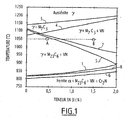
- the inventors have discovered that silicon causes the stable precipitation of carbide (Fe, Cr) 7 C 3 over a wide range of austenization temperatures when its content is greater than 1%, as illustrated in FIG. figure 1 which represents a pseudo-binary cut, as a function of the silicon content, of the phase diagram of a steel composition according to the invention.
- Table 1 Composition of the samples tested Elements (% by weight) VS Yes mn Or Cr MB V NOT W Nb Cu Co al Ti S P A (reference) 0.55 0.43 0.45 0.09 15.5 0.3 0.31 0.12 ⁇ 0.02 ⁇ 0.01 0,022 0.018 ⁇ 0.025 ⁇ 0.010 0.0016 0.0079 B 0.55 1.45 0.52 0.09 15.7 0.3 0.39 0.12 ⁇ 0.02 ⁇ 0.01 0,022 0.018 ⁇ 0.025 ⁇ 0.010 0.0018 0.0082
- the two castings have a C + N content of 0.67%, close to the maximum limit of the invention (0.70%).
- the martensitic or bainitic conversion rate of the composition A remains always very high for all the imposed cooling rates, which correspond to air cooling of the core of bars of diameters of between 25 and 200 mm. This material will therefore be sensitive to the formation of taps at various stages of its shaping.
- the composition B enriched in silicon according to the invention is rapidly transformed at high temperature (between 700 and 800 ° C.), according to a decomposition of the austenite into ferrite, carbides and nitrides.
- the decomposition of the austenite of this silicon-rich steel strongly resembles the classical pearlitic transformation of carbon steels.
- the residual rate of martensitic transformation is negligible for all the cooling rates corresponding to an air cooling at the core of bars of diameters greater than or equal to 50 mm, and remains limited to the core. 25mm diameter.
- the full martensitic transformation of the composition B of the invention remains possible by applying a high cooling rate.
- the steel B structure is martensitic and has a hardness of 58 HRC. It is, moreover, considerably finer and homogeneous than that of steel A.
- it is the carbides (Fe, Cr) 7 C 3 which are present in the steel B, whereas it is the carbides (Fe, Cr) 23 C 6 which are present in the steel AT.
- Carbon is the essential element for imparting its hardness to martensite, or possibly to bainite, formed during quenching. Its minimum content must be 0.45% to reach a hardness of 58 HRC after heat treatment, but also to achieve a metallurgical structure free of delta ferrite.
- Silicon is a major addition element of the invention. In order to obtain the desired low quenchability, its content must be greater than 1%, preferably greater than 1.4%. It is limited to a maximum of 2.5%, so as to maintain a stable ferrite-free structure. Silicon offers a second very favorable action for the use of steel by reinforcing its resistance to oxidation and corrosion by sulfur: it completes the action of chromium. It is also an efficient and inexpensive deoxidation element. However, silicon lowers the melting temperature (solidus) of the steel, which reduces the forgeability range.
- the maximum silicon content will be limited to 2% when looking for the best malleability at high temperature, up to 1200 ° C.
- Chromium is an essential element of the steel used in the invention and allows its protection vis-à-vis the environments of the intake valve. These, in diesel engines with exhaust gas re-injection, are constituted in operation by hot oxidizing gases, and possibly sulphurous depending on the sulfur content in the fuel. The condensates of these gases are also corrosive.
- the chromium oxide that forms on the surface of the steel is truly continuous and protective only for a minimum average content in the steel matrix of 12%. It is therefore considered that this value is the minimum content of chromium within the scope of the invention. In view of the fact that the carbon present in the steel fixes a fraction of the chromium, and that this fraction is therefore no longer available for the formation of the oxide film, the minimum content of chromium in the composition is, however, preferably 14%.
- the maximum chromium content is dictated by the metallurgical equilibrium of the steel and, in particular, by the desire to obtain a purely austenitic, ferrite-free matrix structure at the heat treatment and heat transformation temperatures. Without the addition of nickel, which maintains the austenitic structure but is also expensive, and in the presence of carbon + nitrogen contents of 0.55 to 0.70% as required by the invention, the maximum permissible content of chromium is 18%. As a consequent addition of silicon is practiced in the invention, and since this element has an effect similar to chromium, that is to say, it favors the appearance of the ferritic phase, the maximum chromium content is preferably limited to 16%. Beyond this, there is a risk of occurrence of delta ferrite when the contents of Si are high and the contents of C + N low.
- Nitrogen addition is practiced up to a maximum content of 0.15%, preferably up to 0.12%, so as not to exceed the maximum solubility of this element during solidification. This would lead to the formation of gas bubbles in the metal, resulting in the appearance of pores (blisters) on the solidified metal.
- Inexpensive nitrogen is used as a carbon additive for two reasons.
- nitrogen is beneficial to the corrosion resistance of steel in the presence of corrosive condensates.
- the minimum nitrogen content is 0.05%, and must be such that C + N ⁇ 0.55% so as to achieve the correct composition balance (absence of delta ferrite). It must be such that C + N ⁇ 0.70% so that the maximum levels of carbon and nitrogen as defined above are not exceeded.
- Vanadium addition is practiced to form nitride and vanadium carbide precipitates with nitrogen and carbon which are stable at the heat treatment temperatures. This makes it possible to limit the magnification of the grain of the structure at these temperatures, where a recrystallization of the metal transformed by rolling or forging occurs.
- Vanadium nitrides and carbides are favorable for the abrasion resistance of steel, and are also known to increase the creep resistance of martensitic steels.
- vanadium nitride VN makes it possible to limit that of chromium nitride Cr 2 N which depletes the matrix of chromium.
- molybdenum may also be practiced for its effect, known from the prior art, which is to help limit the brittleness of steel treated for high hardness.
- a significant effect begins to exist from 0.2%.
- a maximum content of 0.5% is allowed not to unnecessarily increase the material cost of steel.
- These materials may also contain other residual elements, not essential to the properties of the steel used in the invention, and may therefore be present only in the form of traces.
- the residual metallic elements that are most often found in the loads resulting from steels to be recycled are essentially manganese, nickel, copper, tungsten, niobium and, more rarely, cobalt.
- Manganese is present in most ferrous raw materials that can be found on the market. It is an easily oxidizable element in furnaces such as the electric arc furnace, but its deliberate and thorough elimination during processing can be costly, and it is not useful in the invention.
- the recycling charges can usually contain up to 2%, which is tolerable within the scope of the invention, and a large fraction is lost anyway by oxidation during production: it is therefore easy to contain the final manganese content less than 1% in the steels used in the invention, through a judicious choice of a mixture of raw materials suitable for conducting the development of steel in the furnaces of steel mills.
- manganese can be harmful at levels greater than 2% since it is known, in general, to reduce the resistance to oxidation and sulfurization, to stabilize the austenite and to increase the martensitic hardenability of the steels. Its maximum residual content should therefore be contained at less than 2% and, preferably, between traces and 1%, which is easy and inexpensive for the steelmaker.
- the steel used in the invention contains levels of manganese and silicon such that their Si / Mn% ratio is greater than or equal to 1, since this condition promotes the flowability of the liquid metal in the casting refractories in the presence a natural atmosphere.
- Nickel is increasingly present in ferrous raw materials recycling: thus, it is common to find it in proportions of 0.2 to 0.4%. Unlike manganese, the nickel of the raw materials is little oxidized during production, for example in conventional electric arc furnaces. It will therefore be almost completely in the final metal.
- the steel used in the invention is an element which greatly increases the quenchability and which is, as such, undesirable at levels greater than 1%.
- it will be contained at most between traces and 0.5%.
- Copper like nickel, is also present in the common ferrous raw materials of recycling, at levels of about 0.1 to 0.2%, even up to 0.4%, and is not eliminated during the elaboration. Copper is known to degrade the forgeability of iron-chromium steels, because it promotes the forming a liquid film in the grain boundaries of the steels when they are brought to the very high temperatures of the thermomechanical transformation range. It is also known that nickel very effectively combats this intergranular "liquefying" mechanism by stabilizing the austenite phase to the detriment of the liquid phase. If nickel is significantly present, the steel used in the invention can therefore tolerate a relatively high copper content.
- Cobalt can exceptionally be found in certain specific raw materials. Like nickel, it is slightly oxidizable during processing in conventional electric arc furnaces. However, unlike nickel, cobalt has no adverse effect on the properties and behavior of the valves of the invention.
- the steel composition used in the invention can therefore comprise up to 1% cobalt, in the form of a residual element.
- Niobium is known to form, at very low levels, stable carbides and nitrides which contribute, in steels, to limiting the magnification of the austenitic grain at the austenization or thermomechanical transformation temperatures. Niobium can therefore effectively complement the role of vanadium for the control of grain size in the steel used in the invention. But niobium is also known to promote the precipitation of eutectic carbides and nitrides in a weakening network during solidification. steel ingots. For these reasons, the niobium content of the steel used in the invention is limited to 0.15%.
- this element can, in some cases, bring strong cohesion to the grain boundaries. If it is desired to add thereto, which is in no way indispensable in the context of the invention, its content must be between traces and 0.0050%, preferably between traces and 0.0020%.
- Aluminum and titanium are to be avoided because they form with nitride weakening nitrides, therefore undesirable.
- the aluminum content should be ⁇ 0.025%, preferably ⁇ 0.015%.
- the titanium content must be ⁇ 0.010%.
- the invention has no particular requirements. Unless particularly good inclusion cleanliness is desired, one is content with the oxygen content naturally resulting from the silicon content (which is generally the predominant deoxidizing element) and the conditions of preparation necessary to obtain the desired levels for the other elements. An oxygen content of the order of 0.0050% or even less can be commonly obtained, but is not imperative in the general case, because the mechanical properties which are primarily to be optimized in the context of the invention depend little on the inclusion cleanliness.
- the steels used in the invention can be prepared according to the methods applicable to common materials, taking into account their particularities. Thus, they can not be developed under vacuum because it is necessary to practice a nitrogen addition in gaseous form.
- an electric furnace, or an AOD reactor, or any other means suitable for the production of steels containing high levels of nitrogen may be used, including secondary refining processes by electroslag remelting.
- the remelting can be done, for example, slag with consumable electrode if one is looking for a high inclusion cleanliness.
- the casting of the metal takes place either by ingots or by continuous casting.
- a homogenizing heat treatment of the solidification structures is feasible, if necessary, at temperatures of between 1150 and 1225 ° C.
- a heat-thermomechanical transformation stage of the cast half-product for example a forging and / or rolling, at temperatures typically between 1000 and 1200 ° C.
- An annealing is optionally applicable after the hot transformation, if it is desired to soften the structure as much as possible for operations at ambient temperature such as straightening of the bars, machining.
- the softening of the products is possible by means of isothermal softening annealing at temperatures between 650 and 900 ° C, for periods of 2 to 8 hours, followed by cooling in the air or in the oven at the rate of cooling the oven.
- localized surface quenching is carried out, for example HF quenching or any other process giving comparable results in areas of high hardness: the seat of the valve seat and / or the end of the stem.
- the bars were then annealed for 8 hours at 880 ° C and then cooled in the oven to 550 ° C, at which temperature the bars were taken out of the oven and cooled in air.
- the hardness of the bars after this softening was then low: 235 HB, or about 22 HRC (the HRC measurement having, at this low level of hardness, greater significance).
- the hardenability limit for air cooling was 40 mm.
- the hardness of the bainitomensitic structure was 58.5 HRC. .
- Table 2 shows examples of income conditions and HRC hardnesses that can be obtained on the previous bars.
- Table 2 HRC hardnesses obtained on steel C according to income conditions. Temperature / time / cooling income hardness HRC 500 ° C / 2h / Air 57.1 525 ° C / 2h / Air 54.4 550 ° C / 2h / Air 47.4 575 ° C / 2h / Air 44.0 600 ° C / 2h / Air 41.1 625 ° C / 2h / Air 39.5 650 ° C / 2h / Air 37.5 700 ° C / 2h / Air 33.1 750 ° C / 2h / Air 29.4 800 ° C / 2h / Air 24.6
- HF quenching has been performed on the end of the stem and / or the seat of the valve seat, to generally give them a hardness of 55 to 60 HRC.
- Another example of treatment according to the invention is the following:
- the cast ingot was homogenized for 8 hours at 1120 ° C, then forged with a pestle into a 17 mm square section bar at a temperature of 1180 ° C.
- the bars were baked in an oven at 650 ° C, for a period of 2 hours, for a metal softening treatment by post-forging isothermal annealing.
- the metal was tested by the "fast" tensile test at the strain rate of 85 mm / s and at temperatures between 1000 and 1230 ° C, in order to assess its malleability in the field. thermomechanical transformation temperatures.
- the malleability of the metal is described by the usual parameters of the tensile test, ie the elongation at break (A%) and the section reduction at the fracture level (Z%).
- the hot resistance is represented by the maximum stress rupture variable (Rm Mpa).
- composition D the sum of the C + N contents of which is situated at the lower limit of the values according to the invention, the martensitic conversion rate, measured as a result of dilatometry tests conducted at various cooling speeds since the temperature of d austenitization of 1050 ° C, becomes negligible for all cooling rates less than or equal to that corresponding to a natural air cooling in the heart of a bar diameter of about 60mm.
- the martensite formed after a faster cooling from 1050 ° C has a hardness of 57.7 HRC.
- This steel E is thus a high carbon chromium-molybdenum martensitic stainless steel of the type X85CrMoV 18-2 previously cited.
- the metal comes from an ingot of about 1.5 tons of industrial casting. This ingot was homogenized at the temperature of 1170 ° C., and then was rolled to the raw diameter 90 mm, starting from this temperature. In addition, the bar used for the test was treated by isothermal annealing at 830 ° C, for softening before peeling and cutting.
- this steel has a marked maximum in a range of limited magnitude between 1120 and 1200 ° C, then drops sharply.
- This steel is therefore significantly less tolerant than steel D at variations in the processing conditions. Above all, in the absolute, its malleability is much lower than that of steel D, its maximum values of A% and Z% being much lower than those of steel D.
- this reference steel E responds significantly less to the technical problems posed than the steels used in the context of the invention.
Priority Applications (1)
| Application Number | Priority Date | Filing Date | Title |
|---|---|---|---|
| PL07730841T PL1979583T3 (pl) | 2006-01-26 | 2007-01-22 | Sposób wytwarzania zaworu do silnika z zapłonem i uzyskany w ten sposób zawór |
Applications Claiming Priority (2)
| Application Number | Priority Date | Filing Date | Title |
|---|---|---|---|
| FR0600724A FR2896514B1 (fr) | 2006-01-26 | 2006-01-26 | Acier martensitique inoxydable et procede de fabrication d'une piece en cet acier, telle qu'une soupape. |
| PCT/FR2007/000121 WO2007085720A1 (fr) | 2006-01-26 | 2007-01-22 | Procédé de fabrication d'une soupape de moteur à explosion, et soupape ainsi obtenue |
Publications (2)
| Publication Number | Publication Date |
|---|---|
| EP1979583A1 EP1979583A1 (fr) | 2008-10-15 |
| EP1979583B1 true EP1979583B1 (fr) | 2011-07-06 |
Family
ID=36997619
Family Applications (1)
| Application Number | Title | Priority Date | Filing Date |
|---|---|---|---|
| EP07730841A Active EP1979583B1 (fr) | 2006-01-26 | 2007-01-22 | Procédé de fabrication d'une soupape de moteur à explosion, et soupape ainsi obtenue |
Country Status (11)
| Country | Link |
|---|---|
| US (1) | US9181824B2 (ja) |
| EP (1) | EP1979583B1 (ja) |
| JP (1) | JP5296554B2 (ja) |
| AR (1) | AR059191A1 (ja) |
| AT (1) | ATE515626T1 (ja) |
| BR (1) | BRPI0706849A2 (ja) |
| ES (1) | ES2367452T3 (ja) |
| FR (1) | FR2896514B1 (ja) |
| PL (1) | PL1979583T3 (ja) |
| TW (1) | TWI403595B (ja) |
| WO (1) | WO2007085720A1 (ja) |
Families Citing this family (13)
| Publication number | Priority date | Publication date | Assignee | Title |
|---|---|---|---|---|
| UA111115C2 (uk) | 2012-04-02 | 2016-03-25 | Ейкей Стіл Пропертіс, Інк. | Рентабельна феритна нержавіюча сталь |
| CA2943511A1 (en) * | 2014-02-18 | 2015-08-27 | Uddeholms Ab | Stainless steel for a plastic mould and a mould made of the stainless steel |
| BR102014016213A2 (pt) * | 2014-06-30 | 2016-02-10 | Mahle Int Gmbh | válvula para motores de combustão interna e processo para obtenção de uma válvula |
| EP3031942B1 (en) * | 2014-12-09 | 2017-07-12 | voestalpine Precision Strip AB | Stainless steel strip for flapper valves |
| JP6196381B2 (ja) | 2014-12-09 | 2017-09-13 | フェストアルピーネ プレジション ストリップ アーベーVoestalpine Precision Strip Ab | フラッパ弁用ステンレス鋼帯 |
| CN104561757A (zh) * | 2014-12-31 | 2015-04-29 | 铜陵市经纬流体科技有限公司 | 一种硼强化珠光体软密封闸阀阀体及其制备方法 |
| WO2016174500A1 (fr) * | 2015-04-30 | 2016-11-03 | Aperam | Acier inoxydable martensitique, procédé de fabrication d'un demi-produit en cet acier et outil de coupe réalisé à partir de ce demi-produit |
| CN105018844B (zh) * | 2015-08-21 | 2017-02-01 | 武汉钢铁(集团)公司 | 低成本高韧性超级耐磨钢及其制备方法 |
| CN106884077B (zh) * | 2017-01-18 | 2021-02-23 | 抚顺特殊钢股份有限公司 | 一种高温合金冷拉材两段式电淬火软化退火工艺 |
| DE102017003965B4 (de) * | 2017-04-25 | 2019-12-12 | Zapp Precision Metals Gmbh | Martensitischer Chromstahl, Stahlfolie, perforierte und/oder gelochte Komponente aus einer Stahlfolie, Verfahren zum Herstellen einer Stahlfolie |
| JP2022535237A (ja) * | 2019-06-05 | 2022-08-05 | エービー サンドビック マテリアルズ テクノロジー | マルテンサイト系ステンレス合金 |
| KR20210071623A (ko) | 2019-12-06 | 2021-06-16 | 현대자동차주식회사 | 엔진 밸브의 제조방법 |
| CN111172471B (zh) * | 2020-02-18 | 2021-02-26 | 北京科技大学 | 一种冰球冰刀材料的制备方法 |
Family Cites Families (21)
| Publication number | Priority date | Publication date | Assignee | Title |
|---|---|---|---|---|
| GB771137A (en) | 1954-01-18 | 1957-03-27 | Nsu Werke Ag | Improvements in or relating to internal conbustion engine rotary valves having curved gas channels and plane working faces |
| JPS55138020A (en) * | 1979-04-09 | 1980-10-28 | Aisan Ind Co Ltd | Poppet valve for internal combustion engine |
| JPS61270335A (ja) * | 1985-05-24 | 1986-11-29 | Toyota Motor Corp | 内燃機関用肉盛バルブ |
| US4737201A (en) | 1986-10-27 | 1988-04-12 | Eaton Corporation | Solution heat treatment of engine poppet valves and valves made therefrom |
| JPS63169326A (ja) * | 1986-12-30 | 1988-07-13 | Honda Motor Co Ltd | 吸気バルブ |
| US4741080A (en) * | 1987-02-20 | 1988-05-03 | Eaton Corporation | Process for providing valve members having varied microstructure |
| JPH01205063A (ja) * | 1988-02-10 | 1989-08-17 | Daido Steel Co Ltd | 耐摩耗ステンレス鋼部品 |
| JPH03106347U (ja) * | 1990-02-16 | 1991-11-01 | ||
| US5257453A (en) | 1991-07-31 | 1993-11-02 | Trw Inc. | Process for making exhaust valves |
| DE4212966C2 (de) * | 1992-04-18 | 1995-07-13 | Ver Schmiedewerke Gmbh | Verwendung eines martensitischen Chrom-Stahls |
| JPH0617609A (ja) | 1992-07-01 | 1994-01-25 | Mazda Motor Corp | エンジンのタペットの製造法 |
| US5330712A (en) * | 1993-04-22 | 1994-07-19 | Federalloy, Inc. | Copper-bismuth alloys |
| DE4406896C1 (de) | 1994-03-03 | 1995-06-29 | Daimler Benz Ag | Verfahren zum Härten von Einmetall-Ventilen, insbesondere von Einlaßventilen für Brennkraftmaschinen |
| DE19620914A1 (de) | 1996-05-24 | 1997-11-27 | Trw Deutschland Gmbh | Nichtrostender Vergütungsstahl für Ventile in Verbrennungsmotoren |
| EP0838533B1 (en) * | 1996-10-25 | 2002-02-13 | Daido Tokushuko Kabushiki Kaisha | Heat resisting alloy for exhaust valve and method for producing the exhaust valve |
| JP3747585B2 (ja) * | 1997-08-25 | 2006-02-22 | 大同特殊鋼株式会社 | 加工性および耐食性に優れた高硬度マルテンサイト系ステンレス鋼 |
| JP3671271B2 (ja) * | 1997-10-03 | 2005-07-13 | 大同特殊鋼株式会社 | エンジン排気バルブの製造方法 |
| JPH11217653A (ja) * | 1998-01-30 | 1999-08-10 | Sanyo Special Steel Co Ltd | 被削性に優れた高耐食高強度マルテンサイト系ステンレス鋼 |
| JPH11335791A (ja) * | 1998-05-26 | 1999-12-07 | Aichi Steel Works Ltd | 高周波焼入用高硬度マルテンサイト系ステンレス鋼 |
| JP2000226641A (ja) * | 1999-02-05 | 2000-08-15 | Nsk Ltd | 転動装置 |
| FR2808807B1 (fr) * | 2000-05-10 | 2002-07-19 | Metallurg Avancee Soc Ind De | Composition d'acier, procede de fabrication et pieces formees dans ces compositions, en particulier soupapes |
-
2006
- 2006-01-26 FR FR0600724A patent/FR2896514B1/fr not_active Expired - Fee Related
-
2007
- 2007-01-22 JP JP2008551817A patent/JP5296554B2/ja active Active
- 2007-01-22 EP EP07730841A patent/EP1979583B1/fr active Active
- 2007-01-22 WO PCT/FR2007/000121 patent/WO2007085720A1/fr active Application Filing
- 2007-01-22 BR BRPI0706849-2A patent/BRPI0706849A2/pt active Search and Examination
- 2007-01-22 PL PL07730841T patent/PL1979583T3/pl unknown
- 2007-01-22 AT AT07730841T patent/ATE515626T1/de active
- 2007-01-22 US US12/159,113 patent/US9181824B2/en active Active
- 2007-01-22 ES ES07730841T patent/ES2367452T3/es active Active
- 2007-01-23 TW TW096102545A patent/TWI403595B/zh active
- 2007-01-25 AR ARP070100333A patent/AR059191A1/es not_active Application Discontinuation
Also Published As
| Publication number | Publication date |
|---|---|
| PL1979583T3 (pl) | 2011-11-30 |
| JP5296554B2 (ja) | 2013-09-25 |
| JP2009524740A (ja) | 2009-07-02 |
| EP1979583A1 (fr) | 2008-10-15 |
| AR059191A1 (es) | 2008-03-12 |
| TW200745350A (en) | 2007-12-16 |
| WO2007085720A1 (fr) | 2007-08-02 |
| FR2896514B1 (fr) | 2008-05-30 |
| US20090301615A1 (en) | 2009-12-10 |
| BRPI0706849A2 (pt) | 2011-04-12 |
| FR2896514A1 (fr) | 2007-07-27 |
| ES2367452T3 (es) | 2011-11-03 |
| TWI403595B (zh) | 2013-08-01 |
| ATE515626T1 (de) | 2011-07-15 |
| US9181824B2 (en) | 2015-11-10 |
Similar Documents
| Publication | Publication Date | Title |
|---|---|---|
| EP1979583B1 (fr) | Procédé de fabrication d'une soupape de moteur à explosion, et soupape ainsi obtenue | |
| EP2310546B1 (fr) | Acier martensitique durci à teneur faible en cobalt, procédé de fabrication d'une pièce à partir de cet acier, et pièce ainsi obtenue | |
| EP1874973B1 (fr) | Acier martensitique durci, procede de fabrication d'une piece a partir de cet acier, et piece ainsi obtenue | |
| EP2164998B1 (fr) | Acier martensitique durci à teneur faible ou nulle en cobalt, procédé de fabrication d'une pièce à partir de cet acier, et pièce ainsi obtenue | |
| EP1426453B1 (fr) | Procédé de fabrication d'une pièce forgée en acier | |
| CA2335911C (fr) | Acier de cementation a temperature de revenu elevee, procede pour son obtention et pieces formees avec cet acier | |
| EP0779375B1 (fr) | Acier pour la fabrication de pièces de mécanique sécables et pièce obtenue | |
| FR2885141A1 (fr) | Acier martensitique durci, procede de fabrication d'une piece a partir de cet acier, et piece ainsi obtenue | |
| EP2247761B1 (en) | Method of making a high strength, high toughness, fatigue resistant, precipitation hardenable stainless steel | |
| CA2559562C (fr) | Acier pour pieces mecaniques, procede de fabrication de pieces mecaniques l'utilisant et pieces mecaniques ainsi realisees | |
| WO1999039018A1 (fr) | Acier et procede pour la fabrication de pieces de mecanique secables | |
| EP1426452B1 (fr) | Procédé de fabrication d'une pièce en acier bainitique | |
| CA2980878C (fr) | Pieces a structure bainitique a hautes proprietes de resistance et procede de fabrication | |
| EP1312691A1 (fr) | Alliage austénitique pour tenue à chaud à coulabilité et transformation améliorées, procédé de fabrication de billettes et de fils | |
| EP1379706B1 (fr) | Acier a outils a tenacite renforcee, procede de fabrication de pieces dans cet acier et pieces obtenues | |
| EP1228253B1 (fr) | Composition d'acier, procede de fabrication et pieces formees dans ces compositions, en particulier soupapes | |
| JP2018165403A (ja) | 低サイクル疲労強度および被削性に優れた浸炭用鋼材および浸炭部品 | |
| KR20180044826A (ko) | 석출 경화형 고 Ni 내열합금 | |
| WO2022253912A1 (fr) | Pièce en acier mise en forme à chaud et procédé de fabrication | |
| MX2008009398A (en) | Method for making spark ignition engine valve, and resulting valve |
Legal Events
| Date | Code | Title | Description |
|---|---|---|---|
| PUAI | Public reference made under article 153(3) epc to a published international application that has entered the european phase |
Free format text: ORIGINAL CODE: 0009012 |
|
| 17P | Request for examination filed |
Effective date: 20080617 |
|
| AK | Designated contracting states |
Kind code of ref document: A1 Designated state(s): AT BE BG CH CY CZ DE DK EE ES FI FR GB GR HU IE IS IT LI LT LU LV MC NL PL PT RO SE SI SK TR |
|
| RIN1 | Information on inventor provided before grant (corrected) |
Inventor name: MONTAGNON, JACQUES |
|
| RTI1 | Title (correction) |
Free format text: METHOD FOR MAKING A COMBUSTION ENGINE VALVE, AND VALVE THUS OBTAINED |
|
| GRAP | Despatch of communication of intention to grant a patent |
Free format text: ORIGINAL CODE: EPIDOSNIGR1 |
|
| GRAS | Grant fee paid |
Free format text: ORIGINAL CODE: EPIDOSNIGR3 |
|
| GRAA | (expected) grant |
Free format text: ORIGINAL CODE: 0009210 |
|
| AK | Designated contracting states |
Kind code of ref document: B1 Designated state(s): AT BE BG CH CY CZ DE DK EE ES FI FR GB GR HU IE IS IT LI LT LU LV MC NL PL PT RO SE SI SK TR |
|
| REG | Reference to a national code |
Ref country code: GB Ref legal event code: FG4D Free format text: NOT ENGLISH |
|
| REG | Reference to a national code |
Ref country code: CH Ref legal event code: EP |
|
| REG | Reference to a national code |
Ref country code: IE Ref legal event code: FG4D Free format text: LANGUAGE OF EP DOCUMENT: FRENCH |
|
| REG | Reference to a national code |
Ref country code: DE Ref legal event code: R096 Ref document number: 602007015632 Country of ref document: DE Effective date: 20110901 |
|
| REG | Reference to a national code |
Ref country code: NL Ref legal event code: VDEP Effective date: 20110706 |
|
| REG | Reference to a national code |
Ref country code: ES Ref legal event code: FG2A Ref document number: 2367452 Country of ref document: ES Kind code of ref document: T3 Effective date: 20111103 |
|
| PG25 | Lapsed in a contracting state [announced via postgrant information from national office to epo] |
Ref country code: SI Free format text: LAPSE BECAUSE OF FAILURE TO SUBMIT A TRANSLATION OF THE DESCRIPTION OR TO PAY THE FEE WITHIN THE PRESCRIBED TIME-LIMIT Effective date: 20110706 |
|
| REG | Reference to a national code |
Ref country code: PL Ref legal event code: T3 |
|
| PG25 | Lapsed in a contracting state [announced via postgrant information from national office to epo] |
Ref country code: PT Free format text: LAPSE BECAUSE OF FAILURE TO SUBMIT A TRANSLATION OF THE DESCRIPTION OR TO PAY THE FEE WITHIN THE PRESCRIBED TIME-LIMIT Effective date: 20111107 Ref country code: SE Free format text: LAPSE BECAUSE OF FAILURE TO SUBMIT A TRANSLATION OF THE DESCRIPTION OR TO PAY THE FEE WITHIN THE PRESCRIBED TIME-LIMIT Effective date: 20110706 Ref country code: NL Free format text: LAPSE BECAUSE OF FAILURE TO SUBMIT A TRANSLATION OF THE DESCRIPTION OR TO PAY THE FEE WITHIN THE PRESCRIBED TIME-LIMIT Effective date: 20110706 Ref country code: IS Free format text: LAPSE BECAUSE OF FAILURE TO SUBMIT A TRANSLATION OF THE DESCRIPTION OR TO PAY THE FEE WITHIN THE PRESCRIBED TIME-LIMIT Effective date: 20111106 Ref country code: FI Free format text: LAPSE BECAUSE OF FAILURE TO SUBMIT A TRANSLATION OF THE DESCRIPTION OR TO PAY THE FEE WITHIN THE PRESCRIBED TIME-LIMIT Effective date: 20110706 Ref country code: LT Free format text: LAPSE BECAUSE OF FAILURE TO SUBMIT A TRANSLATION OF THE DESCRIPTION OR TO PAY THE FEE WITHIN THE PRESCRIBED TIME-LIMIT Effective date: 20110706 |
|
| REG | Reference to a national code |
Ref country code: IE Ref legal event code: FD4D |
|
| PG25 | Lapsed in a contracting state [announced via postgrant information from national office to epo] |
Ref country code: CY Free format text: LAPSE BECAUSE OF FAILURE TO SUBMIT A TRANSLATION OF THE DESCRIPTION OR TO PAY THE FEE WITHIN THE PRESCRIBED TIME-LIMIT Effective date: 20110706 Ref country code: GR Free format text: LAPSE BECAUSE OF FAILURE TO SUBMIT A TRANSLATION OF THE DESCRIPTION OR TO PAY THE FEE WITHIN THE PRESCRIBED TIME-LIMIT Effective date: 20111007 Ref country code: LV Free format text: LAPSE BECAUSE OF FAILURE TO SUBMIT A TRANSLATION OF THE DESCRIPTION OR TO PAY THE FEE WITHIN THE PRESCRIBED TIME-LIMIT Effective date: 20110706 |
|
| PG25 | Lapsed in a contracting state [announced via postgrant information from national office to epo] |
Ref country code: IE Free format text: LAPSE BECAUSE OF FAILURE TO SUBMIT A TRANSLATION OF THE DESCRIPTION OR TO PAY THE FEE WITHIN THE PRESCRIBED TIME-LIMIT Effective date: 20110706 Ref country code: SK Free format text: LAPSE BECAUSE OF FAILURE TO SUBMIT A TRANSLATION OF THE DESCRIPTION OR TO PAY THE FEE WITHIN THE PRESCRIBED TIME-LIMIT Effective date: 20110706 |
|
| PLBE | No opposition filed within time limit |
Free format text: ORIGINAL CODE: 0009261 |
|
| STAA | Information on the status of an ep patent application or granted ep patent |
Free format text: STATUS: NO OPPOSITION FILED WITHIN TIME LIMIT |
|
| PG25 | Lapsed in a contracting state [announced via postgrant information from national office to epo] |
Ref country code: RO Free format text: LAPSE BECAUSE OF FAILURE TO SUBMIT A TRANSLATION OF THE DESCRIPTION OR TO PAY THE FEE WITHIN THE PRESCRIBED TIME-LIMIT Effective date: 20110706 Ref country code: EE Free format text: LAPSE BECAUSE OF FAILURE TO SUBMIT A TRANSLATION OF THE DESCRIPTION OR TO PAY THE FEE WITHIN THE PRESCRIBED TIME-LIMIT Effective date: 20110706 |
|
| 26N | No opposition filed |
Effective date: 20120411 |
|
| PG25 | Lapsed in a contracting state [announced via postgrant information from national office to epo] |
Ref country code: DK Free format text: LAPSE BECAUSE OF FAILURE TO SUBMIT A TRANSLATION OF THE DESCRIPTION OR TO PAY THE FEE WITHIN THE PRESCRIBED TIME-LIMIT Effective date: 20110706 |
|
| BERE | Be: lapsed |
Owner name: AUBERT & DUVAL Effective date: 20120131 |
|
| REG | Reference to a national code |
Ref country code: DE Ref legal event code: R097 Ref document number: 602007015632 Country of ref document: DE Effective date: 20120411 |
|
| PG25 | Lapsed in a contracting state [announced via postgrant information from national office to epo] |
Ref country code: MC Free format text: LAPSE BECAUSE OF NON-PAYMENT OF DUE FEES Effective date: 20120131 |
|
| REG | Reference to a national code |
Ref country code: CH Ref legal event code: PL |
|
| PG25 | Lapsed in a contracting state [announced via postgrant information from national office to epo] |
Ref country code: CH Free format text: LAPSE BECAUSE OF NON-PAYMENT OF DUE FEES Effective date: 20120131 Ref country code: LI Free format text: LAPSE BECAUSE OF NON-PAYMENT OF DUE FEES Effective date: 20120131 |
|
| PG25 | Lapsed in a contracting state [announced via postgrant information from national office to epo] |
Ref country code: BE Free format text: LAPSE BECAUSE OF NON-PAYMENT OF DUE FEES Effective date: 20120131 |
|
| PG25 | Lapsed in a contracting state [announced via postgrant information from national office to epo] |
Ref country code: BG Free format text: LAPSE BECAUSE OF FAILURE TO SUBMIT A TRANSLATION OF THE DESCRIPTION OR TO PAY THE FEE WITHIN THE PRESCRIBED TIME-LIMIT Effective date: 20111006 |
|
| PG25 | Lapsed in a contracting state [announced via postgrant information from national office to epo] |
Ref country code: LU Free format text: LAPSE BECAUSE OF NON-PAYMENT OF DUE FEES Effective date: 20120122 |
|
| PGFP | Annual fee paid to national office [announced via postgrant information from national office to epo] |
Ref country code: TR Payment date: 20140117 Year of fee payment: 8 |
|
| PG25 | Lapsed in a contracting state [announced via postgrant information from national office to epo] |
Ref country code: HU Free format text: LAPSE BECAUSE OF FAILURE TO SUBMIT A TRANSLATION OF THE DESCRIPTION OR TO PAY THE FEE WITHIN THE PRESCRIBED TIME-LIMIT Effective date: 20070122 |
|
| REG | Reference to a national code |
Ref country code: FR Ref legal event code: PLFP Year of fee payment: 10 |
|
| REG | Reference to a national code |
Ref country code: FR Ref legal event code: PLFP Year of fee payment: 11 |
|
| PG25 | Lapsed in a contracting state [announced via postgrant information from national office to epo] |
Ref country code: TR Free format text: LAPSE BECAUSE OF NON-PAYMENT OF DUE FEES Effective date: 20150122 |
|
| REG | Reference to a national code |
Ref country code: FR Ref legal event code: PLFP Year of fee payment: 12 |
|
| REG | Reference to a national code |
Ref country code: DE Ref legal event code: R082 Ref document number: 602007015632 Country of ref document: DE Representative=s name: LAVOIX MUNICH, DE |
|
| PGFP | Annual fee paid to national office [announced via postgrant information from national office to epo] |
Ref country code: FR Payment date: 20230124 Year of fee payment: 17 Ref country code: ES Payment date: 20230330 Year of fee payment: 17 Ref country code: CZ Payment date: 20230113 Year of fee payment: 17 Ref country code: AT Payment date: 20230120 Year of fee payment: 17 |
|
| PGFP | Annual fee paid to national office [announced via postgrant information from national office to epo] |
Ref country code: PL Payment date: 20230116 Year of fee payment: 17 Ref country code: IT Payment date: 20230120 Year of fee payment: 17 |
|
| PGFP | Annual fee paid to national office [announced via postgrant information from national office to epo] |
Ref country code: ES Payment date: 20240223 Year of fee payment: 18 |
|
| PGFP | Annual fee paid to national office [announced via postgrant information from national office to epo] |
Ref country code: AT Payment date: 20240122 Year of fee payment: 18 |
|
| PGFP | Annual fee paid to national office [announced via postgrant information from national office to epo] |
Ref country code: DE Payment date: 20240119 Year of fee payment: 18 Ref country code: CZ Payment date: 20240115 Year of fee payment: 18 Ref country code: GB Payment date: 20240119 Year of fee payment: 18 |