EP1979024B1 - Sicherheitsnadelanordnung mit richtiger medikamentenverbindung - Google Patents
Sicherheitsnadelanordnung mit richtiger medikamentenverbindung Download PDFInfo
- Publication number
- EP1979024B1 EP1979024B1 EP07762954.1A EP07762954A EP1979024B1 EP 1979024 B1 EP1979024 B1 EP 1979024B1 EP 07762954 A EP07762954 A EP 07762954A EP 1979024 B1 EP1979024 B1 EP 1979024B1
- Authority
- EP
- European Patent Office
- Prior art keywords
- adapter
- hub
- fluid
- configuration
- receptacle
- Prior art date
- Legal status (The legal status is an assumption and is not a legal conclusion. Google has not performed a legal analysis and makes no representation as to the accuracy of the status listed.)
- Not-in-force
Links
Images


Classifications
-
- A—HUMAN NECESSITIES
- A61—MEDICAL OR VETERINARY SCIENCE; HYGIENE
- A61M—DEVICES FOR INTRODUCING MEDIA INTO, OR ONTO, THE BODY; DEVICES FOR TRANSDUCING BODY MEDIA OR FOR TAKING MEDIA FROM THE BODY; DEVICES FOR PRODUCING OR ENDING SLEEP OR STUPOR
- A61M5/00—Devices for bringing media into the body in a subcutaneous, intra-vascular or intramuscular way; Accessories therefor, e.g. filling or cleaning devices, arm-rests
- A61M5/178—Syringes
- A61M5/31—Details
- A61M5/32—Needles; Details of needles pertaining to their connection with syringe or hub; Accessories for bringing the needle into, or holding the needle on, the body; Devices for protection of needles
- A61M5/3293—Needles; Details of needles pertaining to their connection with syringe or hub; Accessories for bringing the needle into, or holding the needle on, the body; Devices for protection of needles characterised by features of the needle hub
-
- A—HUMAN NECESSITIES
- A61—MEDICAL OR VETERINARY SCIENCE; HYGIENE
- A61B—DIAGNOSIS; SURGERY; IDENTIFICATION
- A61B17/00—Surgical instruments, devices or methods
- A61B17/34—Trocars; Puncturing needles
- A61B17/3401—Puncturing needles for the peridural or subarachnoid space or the plexus, e.g. for anaesthesia
-
- A—HUMAN NECESSITIES
- A61—MEDICAL OR VETERINARY SCIENCE; HYGIENE
- A61M—DEVICES FOR INTRODUCING MEDIA INTO, OR ONTO, THE BODY; DEVICES FOR TRANSDUCING BODY MEDIA OR FOR TAKING MEDIA FROM THE BODY; DEVICES FOR PRODUCING OR ENDING SLEEP OR STUPOR
- A61M5/00—Devices for bringing media into the body in a subcutaneous, intra-vascular or intramuscular way; Accessories therefor, e.g. filling or cleaning devices, arm-rests
- A61M5/14—Infusion devices, e.g. infusing by gravity; Blood infusion; Accessories therefor
- A61M5/158—Needles for infusions; Accessories therefor, e.g. for inserting infusion needles, or for holding them on the body
-
- A—HUMAN NECESSITIES
- A61—MEDICAL OR VETERINARY SCIENCE; HYGIENE
- A61M—DEVICES FOR INTRODUCING MEDIA INTO, OR ONTO, THE BODY; DEVICES FOR TRANSDUCING BODY MEDIA OR FOR TAKING MEDIA FROM THE BODY; DEVICES FOR PRODUCING OR ENDING SLEEP OR STUPOR
- A61M5/00—Devices for bringing media into the body in a subcutaneous, intra-vascular or intramuscular way; Accessories therefor, e.g. filling or cleaning devices, arm-rests
- A61M5/14—Infusion devices, e.g. infusing by gravity; Blood infusion; Accessories therefor
- A61M5/165—Filtering accessories, e.g. blood filters, filters for infusion liquids
-
- A—HUMAN NECESSITIES
- A61—MEDICAL OR VETERINARY SCIENCE; HYGIENE
- A61M—DEVICES FOR INTRODUCING MEDIA INTO, OR ONTO, THE BODY; DEVICES FOR TRANSDUCING BODY MEDIA OR FOR TAKING MEDIA FROM THE BODY; DEVICES FOR PRODUCING OR ENDING SLEEP OR STUPOR
- A61M39/00—Tubes, tube connectors, tube couplings, valves, access sites or the like, specially adapted for medical use
- A61M39/10—Tube connectors; Tube couplings
- A61M2039/1094—Tube connectors; Tube couplings at least partly incompatible with standard connectors, e.g. to prevent fatal mistakes in connection
-
- A—HUMAN NECESSITIES
- A61—MEDICAL OR VETERINARY SCIENCE; HYGIENE
- A61M—DEVICES FOR INTRODUCING MEDIA INTO, OR ONTO, THE BODY; DEVICES FOR TRANSDUCING BODY MEDIA OR FOR TAKING MEDIA FROM THE BODY; DEVICES FOR PRODUCING OR ENDING SLEEP OR STUPOR
- A61M2205/00—General characteristics of the apparatus
- A61M2205/60—General characteristics of the apparatus with identification means
- A61M2205/6045—General characteristics of the apparatus with identification means having complementary physical shapes for indexing or registration purposes
-
- A—HUMAN NECESSITIES
- A61—MEDICAL OR VETERINARY SCIENCE; HYGIENE
- A61M—DEVICES FOR INTRODUCING MEDIA INTO, OR ONTO, THE BODY; DEVICES FOR TRANSDUCING BODY MEDIA OR FOR TAKING MEDIA FROM THE BODY; DEVICES FOR PRODUCING OR ENDING SLEEP OR STUPOR
- A61M39/00—Tubes, tube connectors, tube couplings, valves, access sites or the like, specially adapted for medical use
- A61M39/10—Tube connectors; Tube couplings
- A61M39/1011—Locking means for securing connection; Additional tamper safeties
-
- Y—GENERAL TAGGING OF NEW TECHNOLOGICAL DEVELOPMENTS; GENERAL TAGGING OF CROSS-SECTIONAL TECHNOLOGIES SPANNING OVER SEVERAL SECTIONS OF THE IPC; TECHNICAL SUBJECTS COVERED BY FORMER USPC CROSS-REFERENCE ART COLLECTIONS [XRACs] AND DIGESTS
- Y10—TECHNICAL SUBJECTS COVERED BY FORMER USPC
- Y10T—TECHNICAL SUBJECTS COVERED BY FORMER US CLASSIFICATION
- Y10T29/00—Metal working
- Y10T29/49—Method of mechanical manufacture
- Y10T29/49826—Assembling or joining
Definitions
- the present invention relates to a needle assembly, such as for example a spinal or epidural needle assembly, and more particularly to a needle assembly that is designed to mate with an adapter for correct connection to a particular medication store or line.
- the instant invention needle assembly includes a needle that has a needle hub specifically configured to have formation(s) thereon that allows it to be connected only to one end of an adapter, which is configured to have a complementary configuration that allows it and the needle hub to readily mate with each other.
- the other end of the adapter has a conventional receptacle end, which may be in the form of a luer that allows it to be connected to a conventional luer fitted medication store, such as for example a syringe or a medication fluid line.
- the hub of the needle assembly of the instant invention as it is configured to have a particular configuration, is not fittable to a conventional luer. Accordingly, the needle assembly could not be mistakenly connected to a fluid store that may contain medicament that, if injected to a patient, may cause harm to the patient.
- the adapter that connects the needle to the appropriate medicament store has a lock mechanism that prevents the removal of the fluid store once the correct fluid store is connected to the adapter. This ensures that no more medication than necessary be injected to the patient, and also that the correct medicament be provided to the patient from the correct mating of the medicament store and the needle.
- the lock mechanism for the instant invention is an integral part of the adapter in that the adapter is made up of two components, namely an adapter core and a shroud that fits about the adapter core.
- the adapter core is fitted to the shroud during manufacturing.
- the adapter core has a pair of pawls formed at a substantially central portion of its circumferential outer surface or wall. These pawls act against ramped stops formed on the interior circumferential surface or wall of the shroud, when the adapter core and the shroud are rotated relative to each other.
- the fluid store (or fluid line) may no longer be removed from the adapter, as rotation in the direction that ordinarily would have uncoupled the receptacle end of the fluid store from the adapter would cause the receptacle end of the adapter to rotate in unison with the fluid store, thereby preventing the receptacle end of the fluid store and the receptacle end of the adapter from disengaging.
- whatever medicament stored in the fluid store that is meant to be used with the needle which would only mate with the particular adapter, could only be used with the needle, thereby preventing any possible mis-connection of a different medicament container to the needle, which may still be inserted to the patient.
- the instant invention therefore relates to an apparatus that comprises a needle assembly that includes a hub having a given configuration at its receptacle end and a needle extending from its closed end, and an adapter having a first end with a first configuration complementary to the given configuration for mating with the hub at its receptacle end.
- the adapter further has a second end with a second configuration so that a fluid store, or a fluid line, that has a receptacle end with a configuration complementary to the second configuration is adaptable to mate with the second end of the adapter.
- the instant invention also relates to a combination in which a needle assembly having a needle hub with a receptacle end of a given configuration and a needle extending from its closed end is combined with an adapter having a first end with a configuration complementary to the given configuration so that the needle hub and the first end of the adapter are readily matable with each other.
- the adapter has a second end with a second configuration that allows the adapter to be coupled to the receptacle end of a fluid store, or a fluid line.
- the adapter further acts as a locking mechanism to prevent the fluid store (or the fluid line), once coupled to the adapter, from rotating in a direction relative to the adapter that allows the fluid store from being uncoupled from the adapter.
- the instant invention further relates to a method of coupling a needle assembly including a hub having a receptacle end and a needle extending from its closed end to an appropriate medicament fluid store or fluid line.
- the method includes the steps of: a) effecting a given configuration at the receptacle end of the hub; b) providing an adapter with a first end having a first configuration complementary to the given configuration for mating with the hub at its receptacle end; c) effecting a second configuration to a second send of the adapter; and d) providing a fluid store or a fluid line having a receptacle end with a configuration complementary to the second configuration for mating with the second end of the adapter.
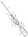
- the instant invention as shown in Fig. 1 , includes a needle assembly 2 that has a needle hub 4.
- Needle hub 4 has a receptacle end 6 and a closed end 8 from which a needle 10 extends.
- Needle 10 may be a conventional needle, but for the instant embodiment is an epidural or a spinal needle for insertion to a patient.
- the closed end 8 is separated from the rest of needle hub 4 by a flange 12.
- Receptacle end of needle hub 4 comprises an elongate cylindrical portion whereat a particular formation, or formations, are effected during the manufacturing process for providing a particular or given configuration that is unique to the needle assembly.
- the thickness of the circumferential wall of the elongate cylindrical portion 14 is dimensioned to provide a further attribute of the configuration of needle hub 4, i.e., configuring the cross section of opening 18 at receptacle end 6 and the through passage into needle hub 4.
- Opening 18 is of a sufficient dimension to accept the receptacle end of an adapter 20 to which needle hub 4 of the needle assembly 2 mates with.
- Protrusions 16a and 16b are formed on the receptacle end 6 of needle hub 4 a particular distance from opening 18 as part of the formation for effecting the proper mating with adapter 20, more specifically with the receptacle end thereof and the shroud component of adapter 20, to be discussed later.
- adapter 20 has another receptacle end 24, which may be configured as a conventional luer end for mating with the conventional luer en d 26 of a fluid store, such as for example a syringe 28.
- a fluid line having fitted to its end a luer such as 26 is also contemplated.
- the receptacle end 26 of syringe 28 is able to mate with receptacle end 24 of a adapter 20, it could not mate with the receptacle end 6 of needle assembly 2.
- Receptacle end 26 of syringe 28 has a male receptacle end 29 and is internally threaded, as represented by the dotted threaded line 30.
- Fig. 2 shows the different components of adapter 20 in relation to needle assembly 2.
- adapter 20 comprises an adapter core 32 and a shroud 34 that is adapted to fit about core 32.
- adapter core 32 has a receptacle end 24, which may also be referred to as its second or distal end.
- core 32 has a first receptacle end 36, or a first or proximal end, for mating with receptacle end 6 of needle hub 4.
- the first end 36 and the second end 24 of adapter core 32 are connected, as adapter core 32 is a single molded piece, by a through passage 40 ( Fig. 4b ) that extends from the opening at first end 36 to the opening at second end 24.
- Shroud 34 and adapter core 32 are separate pieces that may be molded from conventional medical plastics.
- Needle assembly is shown in side views 3a and 3b.
- Fig. 3a shows the receptacle end 6 of needle hub 4 of the needle assembly 2 being covered by a cap 39 that has extending therefrom a thin cannula (not shown) inserted within needle 10 to prevent coring, or the blocking of the needle opening 10a, when needle 10 is inserted to the patient. It is only after needle 10 has been properly inserted into the patient would the user remove cap 38, and therefore the cannula inserted in needle 10. At which time, fluid may pass between needle 10 and the patient through opening 10a at the tip of needle 10.
- Adapter core 32 of adapter 20 of the instant invention has an elongate conical first end 36 and a cylindrical second end 24, which has at its end flanges 24a for forming a conventional luer connection.
- a through passage 40 extends from the opening at first end 36 to the opening at second end 24.
- a flange 42 that separates the first end from the second end provides a back stop, when adapter core 36 is fitted into shroud 34 (or conversely shroud 34 being fitted about adapter core 32), as shown in Fig. 1 .
- a tapered circumferential portion 44 enables adapter core 32 to be inserted to shroud 34, and be fixedly but rotatably retained within shroud 34.
- Shroud 34 is shown in Figs. 5a-5g to have a first opening 46 and a second opening 48. Opening 46 is fabricated to have a configuration that is complementary to the configuration of the formation at receptacle end 6 of needle assembly 2, as discussed above. In particular, as shown in Fig. 5b , opening 46 of shroud 34 has a formation in the shape of a circle, but with two side inlets or channels 46a that allow the corresponding protrusions 16 of needle hub 4 to pass through.
- receptacle end 6 of needle hub 4 once inserted to opening 46, may be secured to shroud 34 by the relative rotation of hub 4 and shroud 34, so that protrusions 16 of needle hub may travel along the internal thread of shroud 34, and receptacle end 6 via its opening 18 be more fully mated-with the receptacle end 36 of adapter core 32. Once fully threaded, needle hub 4 is securely mated to adapter 20.
- Adapter core 32 is pressedly fitted to shroud 34 in the direction as shown by directional arrow 48 in Fig. 5e and 5f .
- the portion of adapter core 32 designated 32a in Fig. 4b , is fitted and held by shroud 34 at portion 34a, as shown in Figs. 5e and 5f .
- adapter core 32 once adapter core 32 is fitted into shroud 34, it cannot be removed therefrom.
- shroud 34 Also provided in shroud 34 are a number of ramped stops 52, as best shown in Fig. 5g , that prevent adapter core 32 from rotating in a direction where the stop surfaces 52s would bias against pawl stops 38b.
- ramped stops 52 are also provided in shroud 34.
- adapter 20 can readily be coupled to the fluid store.
- a fluid store such as for example syringe 28 shown in Fig. 1
- adapter 20 can readily be coupled to the fluid store.
- any attempt to remove adapter 20 from syringe 28, by for example rotating adapter 2 (more specifically shroud 34) counterclockwise relative to syringe 28 would fail, as adapter core 32 would move (rotation or non-rotation) in unison with syringe 28, while the movement of shroud 34 (non-rotation or rotation) would be independent of the unified movement of adapter core 32 and syringe 28.
- FIG. 6 Another aspect of the instant invention is shown in Fig. 6 .
- a filter device 56 is shown to be interposedly connectable to adapter 20 and needle assembly 2.
- Filter device 56 in addition to having a filter element 58, has a first end 60 that has a configuration that is complementary to the configuration of the receptacle end 6 of needle hub 4 of the needle assembly 2.
- the configuration of the receptacle end 60 for filter device 56 is the same as the configuration of the receptacle end 36 of adapter 20.
- filter device 56 has a second end 62 for mating with adapter 20 that has a configuration that is the same as the configuration of receptacle end 6 of needle hub 4.
- filter device 56 filters the fluid passing between the needle assembly 2 and adapter 20, and of course the fluid store that is connected to end 24 of adapter 20.
- the filter element 58 of filter device 56 may be any conventional medical filter that is adaptable to filter out undesirable particles or elements that may be in the fluid.
Landscapes
- Health & Medical Sciences (AREA)
- Life Sciences & Earth Sciences (AREA)
- General Health & Medical Sciences (AREA)
- Anesthesiology (AREA)
- Veterinary Medicine (AREA)
- Public Health (AREA)
- Engineering & Computer Science (AREA)
- Biomedical Technology (AREA)
- Heart & Thoracic Surgery (AREA)
- Animal Behavior & Ethology (AREA)
- Vascular Medicine (AREA)
- Hematology (AREA)
- Surgery (AREA)
- Molecular Biology (AREA)
- Medical Informatics (AREA)
- Nuclear Medicine, Radiotherapy & Molecular Imaging (AREA)
- Pathology (AREA)
- Infusion, Injection, And Reservoir Apparatuses (AREA)
Claims (12)
- Vorrichtung, umfassend:eine Nadelanordnung (2) mit einem Ansatz (4) mit einer bestimmten Formation, die während des Herstellungsverfahrens herbeigeführt wurde, um eine vorgegebene Konfiguration an seinem Aufnahmeende (6) bereitzustellen, und einer sich von seinem geschlossenen Ende (8) erstreckenden Nadel (10);einen Adapter (20) mit einem ersten Ende (36 und 46, 46a) mit einer ersten Konfiguration, die zur vorgegebenen Konfiguration komplementär ist, damit sie mit dem Ansatz an seinem Aufnahmeende zusammenpasst, wobei der Adapter ein zweites Ende (24) mit einer zweiten Konfiguration aufweist, wobei die ersten und zweiten Enden durch einen Durchgangskanal (40) durch ein einzelnes Formstück (32) des Adapters verbunden sind; undeinen Fluidspeicher (28) oder eine Fluidleitung mit einem Aufnahmeende (29) mit einer Konfiguration, die zur zweiten Konfiguration komplementär ist, um mit dem zweiten Ende des Adapters zusammenzupassen;wobei der Adapter einen Arretiermechanismus (38, 52) umfasst, um die Entfernung des Aufnahmeendes (29) des Fluidspeichers (28) oder der Fluidleitung vom zweiten Ende (24) des Adapter zu verhindern, nachdem der Fluidspeicher oder die Fluidleitung und der Adapter zusammengefügt wurden, weil eine Drehung in die Richtung, die normalerweise das Aufnahmeende des Fluidspeichers vom zweiten Ende des Adapters gelöst hätte, dazu führen würde, dass sich das zweite Ende des Adapters gemeinsam mit dem Aufnahmeende des Fluidspeichers oder der Fluidleitung dreht, um so zu verhindern, dass sich der Fluidspeicher oder die Fluidleitung und der Adapter aus ihrem Eingriff lösen.
- Vorrichtung nach Anspruch 1, wobei das Aufnahmeende des Ansatzes eine integrierte Formation (16a, 16b) zur Bildung der vorgegebenen Konfiguration aufweist, so dass der Ansatz dazu ausgelegt ist, nur mit einem Gegenstück zu dem Aufnahmeende zusammenzupassen, das eine Konfiguration aufweist, die zu der vorgegebenen Konfiguration komplementär ist.
- Vorrichtung nach Anspruch 2, wobei die integrierte Formation des Aufnahmeendes des Ansatzes zwei Vorsprünge umfasst, die sich von dem Aufnahmeende des Ansatzes aus erstrecken.
- Vorrichtung nach Anspruch 1, wobei der Adapter einen Kragen (34) umfasst, der um einen Adapterkern (32) herum angebracht ist, wobei der Adapterkern das einzelne Formstück ist, wobei die ersten und zweiten Enden (24, 36) des Adapters an entgegengesetzten Enden des Adapterkerns gebildet sind, wobei der Arretiermechanismus wenigstens eine Sperrklinke (38) aufweist, die auf einer äußeren Umfangsseite des Adapterkerns gebildet ist, um zusammen gegen rampenförmige Anschläge (42) zu wirken, die umfangsmäßig entlang einer Innenfläche des Kragens gebildet sind, so dass nach dem Zusammenfügen des Fluidspeichers oder der Fluidleitung mit dem zweiten Ende des Adapters der Fluidspeicher oder die Fluidleitung und der Adapter nicht mehr voneinander gelöst werden können.
- Vorrichtung nach Anspruch 1, wobei die Nadelanordnung eine Epiduralnadel umfasst.
- Vorrichtung nach Anspruch 1, wobei der Adapter einen Adapterkern mit einem Durchgangskanal (40) und einen um den Adapterkern herum angebrachten Kragen umfasst, wobei das erste Ende (36) des Adapterkerns ein verjüngtes inneres Aufnahmeende ist, welches das erste Ende des Adapters bildet, wobei der Kragen gegenüberliegende Einlässe (46a) zu einem Innengewinde (49) aufweist, für Gewindeeingriff mit dem Aufnahmeende des Ansatzes, wenn das Aufnahmeende des Ansatzes mit dem verjüngten inneren Aufnahmeende des Adapterkerns zusammengefügt wird.
- Vorrichtung nach Anspruch 1, wobei die erste Konfiguration des ersten Endes des Adapters nicht mit einer Nadelanordnung verbunden werden kann, die einen herkömmlichen Luer-Adapter aufweist.
- Vorrichtung nach Anspruch 1, ferner umfassend einen Filter (56) mit einem ersten Ende (60) mit einer Konfiguration, die zur vorgegebenen Konfiguration des Ansatzes komplementär ist, und mit einem zweiten Ende (62), das dieselbe vorgegebene Konfiguration wie der Ansatz aufweist, wobei der Filter dazu ausgelegt ist, verbindbar zwischen der Nadelanordnung und dem Adapter angeordnet zu werden, indem sein erstes Ende mit dem Aufnahmeende des Ansatzes verbunden wird und sein zweites Ende mit dem ersten Ende des Adapters verbunden wird.
- Verfahren zur Verbindung einer Nadelanordnung, die einen Ansatz mit einem Aufnahmeende und einer sich von seinem geschlossenen Ende aus ersteckenden Nadel aufweist, mit einem angemessenen Medikamentenfluidspeicher oder einer Fluidleitung, das die folgenden Schritte umfasst:a) Herbeiführen einer bestimmten Formation während des Herstellungsverfahrens, um eine vorgegebene Konfiguration am Aufnahmeende des Ansatzes bereitzustellen;b) Bereitstellen eines Adapters mit einem ersten Ende mit einer ersten Konfiguration, die zur vorgegebenen Konfiguration komplementär ist, damit sie mit dem Ansatz an seinem Aufnahmeende zusammenpasst;c) Herbeiführen einer zweiten Konfiguration an einem zweiten Ende des Adapters, wobei die ersten und zweiten Enden durch einen Durchgangskanal durch ein einzelnes Formstück des Adapters verbunden sind;d) Bereitstellen eines Fluidspeichers oder einer Fluidleitung mit einem Aufnahmeende mit einer Konfiguration, die zur zweiten Konfiguration komplementär ist, um mit dem zweiten Ende des Adapters zusammenzupassen; unde) Bereitstellen eines Arretiermechanismus an dem Adapter, um die Entfernung des Aufnahmeendes des Fluidspeichers oder der Fluidleitung vom zweiten Ende des Adapters zu verhindern, nachdem der Fluidspeicher oder die Fluidleitung und der Adapter zusammengefügt wurden, weil eine Drehung in die Richtung, die normalerweise das Aufnahmeende des Fluidspeichers oder der Fluidleitung vom zweiten Ende des Adapters gelöst hätte, dazu führen würde, dass sich das zweite Ende des Adapters gemeinsam mit dem Aufnahmeende des Fluidspeichers oder der Fluidleitung dreht, um so zu verhindern, dass sich der Fluidspeicher oder die Fluidleitung und der Adapter aus ihrem Eingriff lösen.
- Verfahren nach Anspruch 9, wobei der Schritt a ferner den folgenden Schritt umfasst:Bereitstellen einer integrierten Formation am Aufnahmeende des Ansatzes zur Bildung der vorgegebenen Konfiguration, so dass der Ansatz dazu ausgelegt ist, nur mit einem Gegenstück zu dem Aufnahmeende zusammenzupassen, das eine Konfiguration aufweist, die zu der vorgegebenen Konfiguration komplementär ist.
- Verfahren nach Anspruch 9, wobei der Schritt b ferner die folgenden Schritte umfasst:Bereitstellen eines Adapterkerns und eines Kragens, der um den Adapterkern herum angebracht werden kann, als Teile des Adapters, wobei der Adapterkern das einzelne Formstück ist;Bilden der ersten und zweiten Enden des Adapters an entgegengesetzten Enden des Adapterkerns;Bilden wenigstens einer Sperrklinke auf einer äußeren Umfangsseite des Adapterkerns und von rampenförmigen Anschlägen umfangsmäßig entlang einer Innenfläche des Kragens;drehendes Anbringen des Kragens um den Adapterkern zur Bildung des Adapters;wobei nach dem Zusammenfügen des Fluidspeichers oder der Fluidleitung mit dem zweiten Ende des Adapters die Sperrklinke des Adapterkerns mit den rampenförmigen Anschlägen des Kragens zusammenarbeiten würde, damit der Fluidspeicher oder die Fluidleitung nur in eine Richtung drehbar sind, die es nicht gestattet, dass der Adapter und der Fluidspeicher oder die Fluidleitung voneinander gelöst werden.
- Verfahren nach Anspruch 9, ferner den folgenden Schritt umfassend:verbindbares Anordnen eines Filters mit einem ersten Ende mit einer Konfiguration, die zur vorgegebenen Konfiguration des Ansatzes komplementär ist, und mit einem zweiten Ende, das dieselbe vorgegebene Konfiguration wie der Ansatz aufweist, zwischen der Nadelanordnung und dem Adapter, indem das erste Ende des Filters mit dem Aufnahmeende des Ansatzes verbunden wird und das zweite Ende des Filters mit dem ersten Ende des Adapters verbunden wird, um so einen gefilterten Fluidkommunikationsweg zwischen der Nadel und dem Adapter zu bewirken.
Applications Claiming Priority (2)
| Application Number | Priority Date | Filing Date | Title |
|---|---|---|---|
| US11/342,620 US20070179454A1 (en) | 2006-01-31 | 2006-01-31 | Safety needle assembly with correct medication connection |
| PCT/US2007/002004 WO2007089531A2 (en) | 2006-01-31 | 2007-01-24 | Safety needle assembly with correct medication connection |
Publications (3)
| Publication Number | Publication Date |
|---|---|
| EP1979024A2 EP1979024A2 (de) | 2008-10-15 |
| EP1979024A4 EP1979024A4 (de) | 2010-08-25 |
| EP1979024B1 true EP1979024B1 (de) | 2016-11-02 |
Family
ID=38323020
Family Applications (1)
| Application Number | Title | Priority Date | Filing Date |
|---|---|---|---|
| EP07762954.1A Not-in-force EP1979024B1 (de) | 2006-01-31 | 2007-01-24 | Sicherheitsnadelanordnung mit richtiger medikamentenverbindung |
Country Status (7)
| Country | Link |
|---|---|
| US (3) | US20070179454A1 (de) |
| EP (1) | EP1979024B1 (de) |
| JP (3) | JP5059785B2 (de) |
| CN (2) | CN102727966B (de) |
| CA (1) | CA2638018C (de) |
| TW (2) | TWI480074B (de) |
| WO (1) | WO2007089531A2 (de) |
Families Citing this family (33)
| Publication number | Priority date | Publication date | Assignee | Title |
|---|---|---|---|---|
| US7998134B2 (en) | 2007-05-16 | 2011-08-16 | Icu Medical, Inc. | Medical connector |
| US7803140B2 (en) | 2005-07-06 | 2010-09-28 | Icu Medical, Inc. | Medical connector with closeable male luer |
| US10089443B2 (en) | 2012-05-15 | 2018-10-02 | Baxter International Inc. | Home medical device systems and methods for therapy prescription and tracking, servicing and inventory |
| US9168366B2 (en) | 2008-12-19 | 2015-10-27 | Icu Medical, Inc. | Medical connector with closeable luer connector |
| KR101162529B1 (ko) * | 2009-04-24 | 2012-07-03 | 이희영 | 수술사 주입용 주사기 |
| JP5489548B2 (ja) * | 2009-06-15 | 2014-05-14 | テルモ株式会社 | プレフィルドシリンジ |
| US9205248B2 (en) * | 2010-02-24 | 2015-12-08 | Becton, Dickinson And Company | Safety Drug delivery connectors |
| US9056163B2 (en) * | 2010-02-24 | 2015-06-16 | Becton, Dickinson And Company | Safety drug delivery system |
| US8465461B2 (en) * | 2010-07-27 | 2013-06-18 | Becton, Dickinson And Company | Blunt needle safety drug delivery system |
| US9814870B2 (en) | 2010-08-17 | 2017-11-14 | Becton, Dickinson And Company | Non-luer connectors |
| AR083884A1 (es) * | 2010-11-16 | 2013-03-27 | Otsuka Pharma Co Ltd | Jeringa prellenable de doble camara y relleno de aripiprazol en la jeringa |
| US9433768B2 (en) * | 2011-03-25 | 2016-09-06 | Becton, Dickinson And Company | Drug delivery connectors |
| CN103987423B (zh) | 2011-09-09 | 2018-04-13 | Icu医学有限公司 | 具有阻流配合界面的医用连接器 |
| US20140350477A1 (en) * | 2012-01-20 | 2014-11-27 | Young-Hee Lee | Disposable syringe |
| TW201442753A (zh) * | 2013-03-14 | 2014-11-16 | Smiths Medical Asd Inc | 可調適的連結器 |
| US10098816B2 (en) | 2013-05-16 | 2018-10-16 | Becton Dickinson and Company Ltd. | Mechanical friction enhancement for threaded connection incorporating micro-threads |
| US9968771B2 (en) | 2013-05-16 | 2018-05-15 | Becton Dickinson and Company Limited | Mechanical friction enhancement for threaded connection incorporating crushable ribs |
| US9895290B2 (en) | 2013-05-16 | 2018-02-20 | Becton Dickinson and Company Ltd. | Mechanical friction enhancement for threaded connection incorporating opposing barb |
| CA156081S (en) | 2013-10-17 | 2014-11-07 | Otsuka Pharma Co Ltd | Syringe |
| WO2015095254A1 (en) * | 2013-12-18 | 2015-06-25 | Stryker Corporation | Assembly for sequentially percutaneously applying an electrode and an anesthetic to tissue |
| USD741476S1 (en) | 2014-06-20 | 2015-10-20 | Otsuka Pharmaceutical Co., Ltd. | Medical syringe |
| IL239366B (en) * | 2015-06-11 | 2018-07-31 | Kriheli Marino | Components of a fluid transfer apparatus |
| KR101691308B1 (ko) * | 2015-10-30 | 2016-12-29 | 라용국 | 필터 주사기 |
| ITUB20160977A1 (it) * | 2016-02-23 | 2017-08-23 | Brev Angela Srl | Sistema di apertura ed erogazione per contenitori pre-riempiti, relativi contenitori pre-riempiti e procedimenti per la loro realizzazione |
| JP6715384B2 (ja) | 2016-08-22 | 2020-07-01 | イーライ リリー アンド カンパニー | 安全な薬剤移送システム |
| US11076883B2 (en) * | 2017-08-21 | 2021-08-03 | Verb Surgical Inc. | Cannula attachment devices and methods for a surgical robotic system |
| USD907193S1 (en) | 2018-02-21 | 2021-01-05 | Eli Lilly And Company | Secured medication transfer set |
| US11235134B2 (en) * | 2018-07-11 | 2022-02-01 | Becton, Dickinson And Company | Neuraxial connector |
| EP3946522A1 (de) * | 2019-04-01 | 2022-02-09 | Credence Medsystems, Inc. | Polymere injektionssysteme |
| MX2021015964A (es) * | 2019-07-09 | 2022-02-10 | Becton Dickinson Co | Conector neuroaxial. |
| CN113577461B (zh) * | 2021-08-10 | 2022-03-29 | 温州康洲医疗器材有限公司 | 一种自对位型针座 |
| KR102705613B1 (ko) * | 2022-08-02 | 2024-09-11 | 가톨릭대학교 산학협력단 | 공기주입방지를 위한 필터부가 구비된 의료용 바늘 유닛 |
| USD1105422S1 (en) | 2024-02-09 | 2025-12-09 | Icu Medical, Inc. | Medical connector cover |
Family Cites Families (64)
| Publication number | Priority date | Publication date | Assignee | Title |
|---|---|---|---|---|
| US4020A (en) * | 1845-05-01 | Machine foe | ||
| US3170667A (en) * | 1963-11-04 | 1965-02-23 | Crawford Fitting Co | Quick connect system |
| US3287031A (en) * | 1964-09-21 | 1966-11-22 | William H Simmons | Indexed keyed connection |
| US4076285A (en) * | 1975-08-01 | 1978-02-28 | Erika, Inc. | Laminar flow connector for conduits |
| DE2549177C3 (de) * | 1975-11-03 | 1985-10-03 | Siemens AG, 1000 Berlin und 8000 München | Kupplungsvorrichtung für zahnärztliche Handstücke |
| US4150673A (en) * | 1977-02-03 | 1979-04-24 | Pharmachem Corporation | Coded entry system for blood bag |
| US4137917A (en) * | 1977-05-12 | 1979-02-06 | Cohen Milton J | Syringe filter unit |
| US4116476A (en) * | 1977-11-11 | 1978-09-26 | Porter Gary K | Quick disconnect coupler assembly |
| US4211439A (en) * | 1978-07-26 | 1980-07-08 | Moldestad Jon P | Safety device for hose connections |
| US4280723A (en) * | 1978-07-26 | 1981-07-28 | Moldestad Jon P | Safety device for hose connections |
| US4453927A (en) * | 1979-02-07 | 1984-06-12 | Gesco International | Method and apparatus for microfiltration of blood |
| US4452473A (en) * | 1982-07-26 | 1984-06-05 | Baxter Travenol Laboratories, Inc. | Luer connection system |
| US5776116A (en) * | 1983-01-24 | 1998-07-07 | Icu Medical, Inc. | Medical connector |
| JPS6145774A (ja) * | 1984-08-07 | 1986-03-05 | テルモ株式会社 | 医療用器具 |
| US4619640A (en) * | 1984-08-17 | 1986-10-28 | Potolsky Abraham I | Blood transfusion connector assembly |
| CA1272655A (en) * | 1985-07-31 | 1990-08-14 | Yukihiro Kawano | Connector for plasmapheresis bag |
| GB8527646D0 (en) * | 1985-11-08 | 1985-12-11 | Cox J A | Devices for sampling drainage |
| US4772267A (en) * | 1987-03-27 | 1988-09-20 | Menlo Care, Inc. | Peripheral IV catheter with enlargeable flashback chamber |
| DE3821154C1 (de) * | 1988-06-23 | 1989-10-19 | B. Braun Melsungen Ag, 3508 Melsungen, De | |
| JPH0268072A (ja) * | 1988-09-01 | 1990-03-07 | Terumo Corp | 注射装置 |
| JPH02297342A (ja) * | 1988-09-28 | 1990-12-07 | Terumo Corp | 両刀針形の医療用針とホルダーを用いる採血及び/又は注射装置、並びに該装置に用いる両刀針形の医療用針及びホルダー |
| US4964854A (en) * | 1989-01-23 | 1990-10-23 | Luther Medical Products, Inc. | Intravascular catheter assembly incorporating needle tip shielding cap |
| US4940458A (en) * | 1989-02-02 | 1990-07-10 | Cohn Arnold K | Epidural needle placement system |
| IE72466B1 (en) * | 1989-03-17 | 1997-04-09 | Baxter Int | Blunt-ended cannula device |
| DE69314820T2 (de) * | 1992-01-31 | 1998-02-26 | Becton Dickinson Co | Chirurgischer Dilator |
| US5603706A (en) * | 1992-09-29 | 1997-02-18 | Wyatt; Philip | Infusion apparatus |
| US5405339A (en) * | 1993-09-03 | 1995-04-11 | Medtronic, Inc. | Medical connector and method for connecting medical tubing |
| JP3502135B2 (ja) * | 1993-12-24 | 2004-03-02 | テルモ株式会社 | 血管内挿入用医療器具およびその製造方法 |
| US5562121A (en) * | 1995-04-06 | 1996-10-08 | Allied Healthcare Products, Inc. | Gas delivery system with universal outlet |
| US5620427A (en) * | 1995-04-27 | 1997-04-15 | David R. Kipp | Luer lock system |
| US5605359A (en) * | 1995-06-02 | 1997-02-25 | Dana Corporation | Stabilized hose fitting for coupling |
| US5947937A (en) * | 1995-09-07 | 1999-09-07 | Sharon Ventures, Inc. | Method and apparatus for prevention of blood-type mismatches |
| US5725511A (en) * | 1995-09-07 | 1998-03-10 | Urrutia; Sharon A. | Method and apparatus for prevention of blood-type mismatches |
| US5616133A (en) * | 1995-10-23 | 1997-04-01 | Cardenas; Juan M. | Syringe for epidural catheter |
| IT1281248B1 (it) * | 1995-11-16 | 1998-02-17 | Pier Luigi Delvigo | Dispositivo medico di sicurezza per trasfusioni. |
| JP3892095B2 (ja) * | 1996-01-23 | 2007-03-14 | テルモ株式会社 | 注射器 |
| US5743882A (en) * | 1996-03-08 | 1998-04-28 | Luther Medical Products, Inc. | Needle blunting assembly for use with intravascular introducers |
| US5718690A (en) * | 1996-06-10 | 1998-02-17 | Gettig Technologies, Incorporated | Hypodermic injector system and method for maintaining the sterility thereof prior to use |
| US5741269A (en) * | 1996-11-18 | 1998-04-21 | Mccredy; Doug | Medical vacuum device |
| US6402207B1 (en) * | 1997-06-09 | 2002-06-11 | Qd Enterprises, Llc | Safety indexed medical connectors |
| DE29720182U1 (de) * | 1997-11-14 | 1999-03-25 | B. Braun Melsungen Ag, 34212 Melsungen | Vorrichtung zum Zuführen von Flüssigkeiten zu einem Patienten |
| GB9801261D0 (en) * | 1998-01-21 | 1998-03-18 | Peters Joseph L | Couplings for medical cannulae |
| US6183464B1 (en) * | 1998-06-01 | 2001-02-06 | Inviro Medical Devices Ltd. | Safety syringe with retractable needle and universal luer coupling |
| US6250688B1 (en) * | 1998-06-01 | 2001-06-26 | Micron Technology, Inc. | Ramp-lock lifting device |
| US6592559B1 (en) * | 1998-12-09 | 2003-07-15 | Cook Incorporated | Hollow, curved, superlastic medical needle |
| US6156025A (en) * | 1999-06-17 | 2000-12-05 | Bracco Research Usa Inc. | Twist valve |
| JP2001187990A (ja) * | 1999-12-28 | 2001-07-10 | Ookisu:Kk | 医療用接続部材 |
| EP1286718B1 (de) * | 2000-04-10 | 2007-01-24 | Boston Scientific Limited | Feststellkatheter |
| JP2002028224A (ja) * | 2000-05-10 | 2002-01-29 | Jms Co Ltd | 経胃経腸栄養点滴セット用回路システム |
| US6394979B1 (en) * | 2000-06-09 | 2002-05-28 | Inviro Medical Devices Ltd. | Cannula for use with a medical syringe |
| US6500153B1 (en) * | 2001-07-13 | 2002-12-31 | Children's And Women's Health Centre Of British Columbia | Syringe and needle for preventing inadvertent drug injection |
| US20030105428A1 (en) * | 2001-12-05 | 2003-06-05 | John Hogan | Electronically controlled fluid delivery device |
| ITTO20020111A1 (it) * | 2002-02-08 | 2003-08-08 | Borla Ind | ,,connettore luer lock maschio per linee di fluido medicali,, |
| US6688651B2 (en) * | 2002-02-21 | 2004-02-10 | Dmt Co., Ltd. | Device for locking cap nut for coupling |
| ITTO20020276A1 (it) * | 2002-03-27 | 2003-09-29 | Borla Ind | ,,connettore luer lock maschio per linee di fluido medicali,, |
| US6722705B2 (en) * | 2002-04-25 | 2004-04-20 | Ab Korkor Medical, Inc. | Medical tubing connector |
| US6786131B2 (en) * | 2002-08-27 | 2004-09-07 | Lung-Po Tsai | Valve used for an inflatable article |
| FR2845607B1 (fr) * | 2002-10-10 | 2005-06-24 | Vygon | Connecteur de fluide a usage medical et ses applications |
| US20040122378A1 (en) * | 2002-12-19 | 2004-06-24 | Fu-Yu Hsu | Safety hypodermic syringe |
| US6991608B2 (en) * | 2003-04-03 | 2006-01-31 | Becton, Dickinson And Company | Medical assembly |
| JP4383908B2 (ja) * | 2004-01-29 | 2009-12-16 | 株式会社八光 | 硬膜外針 |
| US7497484B2 (en) * | 2004-08-11 | 2009-03-03 | Smiths Medical Asd, Inc. | Medical coupling system |
| ITTO20050516A1 (it) * | 2005-07-25 | 2007-01-26 | Borla Ind | Connettore medicale |
| ITTO20050515A1 (it) * | 2005-07-25 | 2007-01-26 | Borla Ind | Connettore valvolare medicale |
-
2006
- 2006-01-31 US US11/342,620 patent/US20070179454A1/en not_active Abandoned
-
2007
- 2007-01-18 TW TW102140851A patent/TWI480074B/zh not_active IP Right Cessation
- 2007-01-18 TW TW096101888A patent/TWI480073B/zh not_active IP Right Cessation
- 2007-01-24 WO PCT/US2007/002004 patent/WO2007089531A2/en not_active Ceased
- 2007-01-24 JP JP2008552401A patent/JP5059785B2/ja not_active Expired - Fee Related
- 2007-01-24 CA CA2638018A patent/CA2638018C/en not_active Expired - Fee Related
- 2007-01-24 EP EP07762954.1A patent/EP1979024B1/de not_active Not-in-force
- 2007-01-24 CN CN201210109289.1A patent/CN102727966B/zh not_active Expired - Fee Related
- 2007-01-24 CN CN2007800040030A patent/CN101378798B/zh not_active Expired - Fee Related
-
2012
- 2012-05-09 JP JP2012107603A patent/JP5662377B2/ja not_active Expired - Fee Related
- 2012-09-12 US US13/610,943 patent/US20130046255A1/en not_active Abandoned
- 2012-12-14 US US13/714,501 patent/US20130116631A1/en not_active Abandoned
-
2013
- 2013-09-12 JP JP2013189235A patent/JP5753560B2/ja not_active Expired - Fee Related
Also Published As
| Publication number | Publication date |
|---|---|
| EP1979024A2 (de) | 2008-10-15 |
| CN101378798A (zh) | 2009-03-04 |
| CN101378798B (zh) | 2012-06-20 |
| JP5753560B2 (ja) | 2015-07-22 |
| TWI480073B (zh) | 2015-04-11 |
| JP2014014703A (ja) | 2014-01-30 |
| JP2012166052A (ja) | 2012-09-06 |
| CN102727966B (zh) | 2016-08-03 |
| EP1979024A4 (de) | 2010-08-25 |
| TWI480074B (zh) | 2015-04-11 |
| JP5059785B2 (ja) | 2012-10-31 |
| JP2009525067A (ja) | 2009-07-09 |
| CN102727966A (zh) | 2012-10-17 |
| JP5662377B2 (ja) | 2015-01-28 |
| CA2638018C (en) | 2016-11-08 |
| CA2638018A1 (en) | 2007-08-09 |
| US20130116631A1 (en) | 2013-05-09 |
| US20130046255A1 (en) | 2013-02-21 |
| TW200744694A (en) | 2007-12-16 |
| TW201414516A (zh) | 2014-04-16 |
| US20070179454A1 (en) | 2007-08-02 |
| WO2007089531A2 (en) | 2007-08-09 |
| WO2007089531A3 (en) | 2008-01-10 |
Similar Documents
| Publication | Publication Date | Title |
|---|---|---|
| EP1979024B1 (de) | Sicherheitsnadelanordnung mit richtiger medikamentenverbindung | |
| US12383466B2 (en) | Fluid transfer device and packaging therefor | |
| CN101360946B (zh) | 医疗联接系统 | |
| US6508807B1 (en) | Coupling for medical cannulae | |
| EP2931207B1 (de) | Phiolenadapter | |
| EP3831439B1 (de) | Verbindungssystem für komponenten medizinischer vorrichtungen | |
| EP2259839B1 (de) | Vorrichtungen, anordnungen und verfahren zur kontrolle des flüssigkeitsflusses | |
| US20160287857A1 (en) | Connector with Seal Element and Adapted Connector Parts | |
| CN113599613A (zh) | 盒、盒组件以及笔式针组件 | |
| CN113975545B (zh) | 注射器的注射头组件和注射器 | |
| MX2008009669A (en) | Safety needle assembly with correct medication connection | |
| HK1175128A (en) | Safety needle assembly with correct medication connection | |
| EP4230242A1 (de) | Adapter zum verbinden eines verbinders mit einer distalen spitze eines medizinischen behälters, spitzenkappenanordnung und arzneimittelabgabevorrichtung zum eingriff mit dem adapter und verfahren zur herstellung des adapters | |
| CN219251198U (zh) | 导管系统 |
Legal Events
| Date | Code | Title | Description |
|---|---|---|---|
| PUAI | Public reference made under article 153(3) epc to a published international application that has entered the european phase |
Free format text: ORIGINAL CODE: 0009012 |
|
| 17P | Request for examination filed |
Effective date: 20080728 |
|
| AK | Designated contracting states |
Kind code of ref document: A2 Designated state(s): AT BE BG CH CY CZ DE DK EE ES FI FR GB GR HU IE IS IT LI LT LU LV MC NL PL PT RO SE SI SK TR |
|
| A4 | Supplementary search report drawn up and despatched |
Effective date: 20100728 |
|
| 17Q | First examination report despatched |
Effective date: 20120417 |
|
| DAX | Request for extension of the european patent (deleted) | ||
| REG | Reference to a national code |
Ref country code: DE Ref legal event code: R079 Ref document number: 602007048570 Country of ref document: DE Free format text: PREVIOUS MAIN CLASS: A61M0005000000 Ipc: A61B0017340000 |
|
| RIC1 | Information provided on ipc code assigned before grant |
Ipc: A61M 5/32 20060101ALI20160404BHEP Ipc: A61B 17/34 20060101AFI20160404BHEP Ipc: A61M 5/158 20060101ALI20160404BHEP Ipc: A61M 39/10 20060101ALI20160404BHEP Ipc: A61M 5/165 20060101ALI20160404BHEP |
|
| GRAP | Despatch of communication of intention to grant a patent |
Free format text: ORIGINAL CODE: EPIDOSNIGR1 |
|
| INTG | Intention to grant announced |
Effective date: 20160602 |
|
| GRAS | Grant fee paid |
Free format text: ORIGINAL CODE: EPIDOSNIGR3 |
|
| GRAA | (expected) grant |
Free format text: ORIGINAL CODE: 0009210 |
|
| AK | Designated contracting states |
Kind code of ref document: B1 Designated state(s): AT BE BG CH CY CZ DE DK EE ES FI FR GB GR HU IE IS IT LI LT LU LV MC NL PL PT RO SE SI SK TR |
|
| RAP1 | Party data changed (applicant data changed or rights of an application transferred) |
Owner name: SMITHS MEDICAL ASD, INC. |
|
| REG | Reference to a national code |
Ref country code: GB Ref legal event code: FG4D |
|
| REG | Reference to a national code |
Ref country code: AT Ref legal event code: REF Ref document number: 840998 Country of ref document: AT Kind code of ref document: T Effective date: 20161115 Ref country code: CH Ref legal event code: EP |
|
| REG | Reference to a national code |
Ref country code: IE Ref legal event code: FG4D |
|
| REG | Reference to a national code |
Ref country code: DE Ref legal event code: R096 Ref document number: 602007048570 Country of ref document: DE Ref country code: FR Ref legal event code: PLFP Year of fee payment: 11 |
|
| PG25 | Lapsed in a contracting state [announced via postgrant information from national office to epo] |
Ref country code: LV Free format text: LAPSE BECAUSE OF FAILURE TO SUBMIT A TRANSLATION OF THE DESCRIPTION OR TO PAY THE FEE WITHIN THE PRESCRIBED TIME-LIMIT Effective date: 20161102 |
|
| REG | Reference to a national code |
Ref country code: NL Ref legal event code: MP Effective date: 20161102 |
|
| REG | Reference to a national code |
Ref country code: LT Ref legal event code: MG4D |
|
| REG | Reference to a national code |
Ref country code: AT Ref legal event code: MK05 Ref document number: 840998 Country of ref document: AT Kind code of ref document: T Effective date: 20161102 |
|
| PG25 | Lapsed in a contracting state [announced via postgrant information from national office to epo] |
Ref country code: SE Free format text: LAPSE BECAUSE OF FAILURE TO SUBMIT A TRANSLATION OF THE DESCRIPTION OR TO PAY THE FEE WITHIN THE PRESCRIBED TIME-LIMIT Effective date: 20161102 Ref country code: NL Free format text: LAPSE BECAUSE OF FAILURE TO SUBMIT A TRANSLATION OF THE DESCRIPTION OR TO PAY THE FEE WITHIN THE PRESCRIBED TIME-LIMIT Effective date: 20161102 Ref country code: LT Free format text: LAPSE BECAUSE OF FAILURE TO SUBMIT A TRANSLATION OF THE DESCRIPTION OR TO PAY THE FEE WITHIN THE PRESCRIBED TIME-LIMIT Effective date: 20161102 Ref country code: GR Free format text: LAPSE BECAUSE OF FAILURE TO SUBMIT A TRANSLATION OF THE DESCRIPTION OR TO PAY THE FEE WITHIN THE PRESCRIBED TIME-LIMIT Effective date: 20170203 |
|
| PG25 | Lapsed in a contracting state [announced via postgrant information from national office to epo] |
Ref country code: PT Free format text: LAPSE BECAUSE OF FAILURE TO SUBMIT A TRANSLATION OF THE DESCRIPTION OR TO PAY THE FEE WITHIN THE PRESCRIBED TIME-LIMIT Effective date: 20170302 Ref country code: ES Free format text: LAPSE BECAUSE OF FAILURE TO SUBMIT A TRANSLATION OF THE DESCRIPTION OR TO PAY THE FEE WITHIN THE PRESCRIBED TIME-LIMIT Effective date: 20161102 Ref country code: PL Free format text: LAPSE BECAUSE OF FAILURE TO SUBMIT A TRANSLATION OF THE DESCRIPTION OR TO PAY THE FEE WITHIN THE PRESCRIBED TIME-LIMIT Effective date: 20161102 Ref country code: AT Free format text: LAPSE BECAUSE OF FAILURE TO SUBMIT A TRANSLATION OF THE DESCRIPTION OR TO PAY THE FEE WITHIN THE PRESCRIBED TIME-LIMIT Effective date: 20161102 Ref country code: IS Free format text: LAPSE BECAUSE OF FAILURE TO SUBMIT A TRANSLATION OF THE DESCRIPTION OR TO PAY THE FEE WITHIN THE PRESCRIBED TIME-LIMIT Effective date: 20170302 Ref country code: FI Free format text: LAPSE BECAUSE OF FAILURE TO SUBMIT A TRANSLATION OF THE DESCRIPTION OR TO PAY THE FEE WITHIN THE PRESCRIBED TIME-LIMIT Effective date: 20161102 Ref country code: BE Free format text: LAPSE BECAUSE OF NON-PAYMENT OF DUE FEES Effective date: 20170131 |
|
| PG25 | Lapsed in a contracting state [announced via postgrant information from national office to epo] |
Ref country code: CZ Free format text: LAPSE BECAUSE OF FAILURE TO SUBMIT A TRANSLATION OF THE DESCRIPTION OR TO PAY THE FEE WITHIN THE PRESCRIBED TIME-LIMIT Effective date: 20161102 Ref country code: SK Free format text: LAPSE BECAUSE OF FAILURE TO SUBMIT A TRANSLATION OF THE DESCRIPTION OR TO PAY THE FEE WITHIN THE PRESCRIBED TIME-LIMIT Effective date: 20161102 Ref country code: DK Free format text: LAPSE BECAUSE OF FAILURE TO SUBMIT A TRANSLATION OF THE DESCRIPTION OR TO PAY THE FEE WITHIN THE PRESCRIBED TIME-LIMIT Effective date: 20161102 Ref country code: EE Free format text: LAPSE BECAUSE OF FAILURE TO SUBMIT A TRANSLATION OF THE DESCRIPTION OR TO PAY THE FEE WITHIN THE PRESCRIBED TIME-LIMIT Effective date: 20161102 Ref country code: RO Free format text: LAPSE BECAUSE OF FAILURE TO SUBMIT A TRANSLATION OF THE DESCRIPTION OR TO PAY THE FEE WITHIN THE PRESCRIBED TIME-LIMIT Effective date: 20161102 |
|
| REG | Reference to a national code |
Ref country code: DE Ref legal event code: R097 Ref document number: 602007048570 Country of ref document: DE |
|
| PG25 | Lapsed in a contracting state [announced via postgrant information from national office to epo] |
Ref country code: BE Free format text: LAPSE BECAUSE OF FAILURE TO SUBMIT A TRANSLATION OF THE DESCRIPTION OR TO PAY THE FEE WITHIN THE PRESCRIBED TIME-LIMIT Effective date: 20161102 Ref country code: IT Free format text: LAPSE BECAUSE OF FAILURE TO SUBMIT A TRANSLATION OF THE DESCRIPTION OR TO PAY THE FEE WITHIN THE PRESCRIBED TIME-LIMIT Effective date: 20161102 Ref country code: BG Free format text: LAPSE BECAUSE OF FAILURE TO SUBMIT A TRANSLATION OF THE DESCRIPTION OR TO PAY THE FEE WITHIN THE PRESCRIBED TIME-LIMIT Effective date: 20170202 |
|
| REG | Reference to a national code |
Ref country code: CH Ref legal event code: PL |
|
| PLBE | No opposition filed within time limit |
Free format text: ORIGINAL CODE: 0009261 |
|
| STAA | Information on the status of an ep patent application or granted ep patent |
Free format text: STATUS: NO OPPOSITION FILED WITHIN TIME LIMIT |
|
| PG25 | Lapsed in a contracting state [announced via postgrant information from national office to epo] |
Ref country code: MC Free format text: LAPSE BECAUSE OF FAILURE TO SUBMIT A TRANSLATION OF THE DESCRIPTION OR TO PAY THE FEE WITHIN THE PRESCRIBED TIME-LIMIT Effective date: 20161102 |
|
| 26N | No opposition filed |
Effective date: 20170803 |
|
| PG25 | Lapsed in a contracting state [announced via postgrant information from national office to epo] |
Ref country code: LI Free format text: LAPSE BECAUSE OF NON-PAYMENT OF DUE FEES Effective date: 20170131 Ref country code: CH Free format text: LAPSE BECAUSE OF NON-PAYMENT OF DUE FEES Effective date: 20170131 |
|
| REG | Reference to a national code |
Ref country code: IE Ref legal event code: MM4A |
|
| PG25 | Lapsed in a contracting state [announced via postgrant information from national office to epo] |
Ref country code: LU Free format text: LAPSE BECAUSE OF NON-PAYMENT OF DUE FEES Effective date: 20170124 Ref country code: SI Free format text: LAPSE BECAUSE OF FAILURE TO SUBMIT A TRANSLATION OF THE DESCRIPTION OR TO PAY THE FEE WITHIN THE PRESCRIBED TIME-LIMIT Effective date: 20161102 |
|
| REG | Reference to a national code |
Ref country code: FR Ref legal event code: PLFP Year of fee payment: 12 |
|
| PGFP | Annual fee paid to national office [announced via postgrant information from national office to epo] |
Ref country code: FR Payment date: 20171211 Year of fee payment: 12 |
|
| PG25 | Lapsed in a contracting state [announced via postgrant information from national office to epo] |
Ref country code: IE Free format text: LAPSE BECAUSE OF NON-PAYMENT OF DUE FEES Effective date: 20170124 |
|
| PGFP | Annual fee paid to national office [announced via postgrant information from national office to epo] |
Ref country code: GB Payment date: 20180124 Year of fee payment: 12 Ref country code: DE Payment date: 20180110 Year of fee payment: 12 |
|
| PG25 | Lapsed in a contracting state [announced via postgrant information from national office to epo] |
Ref country code: HU Free format text: LAPSE BECAUSE OF FAILURE TO SUBMIT A TRANSLATION OF THE DESCRIPTION OR TO PAY THE FEE WITHIN THE PRESCRIBED TIME-LIMIT; INVALID AB INITIO Effective date: 20070124 |
|
| REG | Reference to a national code |
Ref country code: DE Ref legal event code: R119 Ref document number: 602007048570 Country of ref document: DE |
|
| GBPC | Gb: european patent ceased through non-payment of renewal fee |
Effective date: 20190124 |
|
| PG25 | Lapsed in a contracting state [announced via postgrant information from national office to epo] |
Ref country code: CY Free format text: LAPSE BECAUSE OF NON-PAYMENT OF DUE FEES Effective date: 20161102 Ref country code: DE Free format text: LAPSE BECAUSE OF NON-PAYMENT OF DUE FEES Effective date: 20190801 Ref country code: FR Free format text: LAPSE BECAUSE OF NON-PAYMENT OF DUE FEES Effective date: 20190131 |
|
| PG25 | Lapsed in a contracting state [announced via postgrant information from national office to epo] |
Ref country code: GB Free format text: LAPSE BECAUSE OF NON-PAYMENT OF DUE FEES Effective date: 20190124 |
|
| PG25 | Lapsed in a contracting state [announced via postgrant information from national office to epo] |
Ref country code: TR Free format text: LAPSE BECAUSE OF FAILURE TO SUBMIT A TRANSLATION OF THE DESCRIPTION OR TO PAY THE FEE WITHIN THE PRESCRIBED TIME-LIMIT Effective date: 20161102 |