EP1978679A2 - Vorrichtung zur drahtlosen Kommunikation - Google Patents
Vorrichtung zur drahtlosen Kommunikation Download PDFInfo
- Publication number
- EP1978679A2 EP1978679A2 EP08251084A EP08251084A EP1978679A2 EP 1978679 A2 EP1978679 A2 EP 1978679A2 EP 08251084 A EP08251084 A EP 08251084A EP 08251084 A EP08251084 A EP 08251084A EP 1978679 A2 EP1978679 A2 EP 1978679A2
- Authority
- EP
- European Patent Office
- Prior art keywords
- communication
- intensity
- specific
- wireless communication
- section
- Prior art date
- Legal status (The legal status is an assumption and is not a legal conclusion. Google has not performed a legal analysis and makes no representation as to the accuracy of the status listed.)
- Granted
Links
- 238000004891 communication Methods 0.000 title claims abstract description 308
- 230000005684 electric field Effects 0.000 claims description 54
- 238000012545 processing Methods 0.000 claims description 33
- 230000001174 ascending effect Effects 0.000 claims description 21
- 230000003247 decreasing effect Effects 0.000 claims description 8
- 238000000034 method Methods 0.000 description 12
- 238000012986 modification Methods 0.000 description 8
- 230000004048 modification Effects 0.000 description 8
- 238000005516 engineering process Methods 0.000 description 1
- 230000001788 irregular Effects 0.000 description 1
- 238000000060 site-specific infrared dichroism spectroscopy Methods 0.000 description 1
Images




Classifications
-
- H—ELECTRICITY
- H04—ELECTRIC COMMUNICATION TECHNIQUE
- H04B—TRANSMISSION
- H04B1/00—Details of transmission systems, not covered by a single one of groups H04B3/00 - H04B13/00; Details of transmission systems not characterised by the medium used for transmission
- H04B1/69—Spread spectrum techniques
- H04B1/713—Spread spectrum techniques using frequency hopping
-
- H—ELECTRICITY
- H04—ELECTRIC COMMUNICATION TECHNIQUE
- H04W—WIRELESS COMMUNICATION NETWORKS
- H04W72/00—Local resource management
- H04W72/50—Allocation or scheduling criteria for wireless resources
- H04W72/56—Allocation or scheduling criteria for wireless resources based on priority criteria
- H04W72/566—Allocation or scheduling criteria for wireless resources based on priority criteria of the information or information source or recipient
- H04W72/569—Allocation or scheduling criteria for wireless resources based on priority criteria of the information or information source or recipient of the traffic information
-
- H—ELECTRICITY
- H04—ELECTRIC COMMUNICATION TECHNIQUE
- H04W—WIRELESS COMMUNICATION NETWORKS
- H04W88/00—Devices specially adapted for wireless communication networks, e.g. terminals, base stations or access point devices
- H04W88/02—Terminal devices
- H04W88/06—Terminal devices adapted for operation in multiple networks or having at least two operational modes, e.g. multi-mode terminals
Definitions
- the present invention relates to a wireless communication apparatus configured to communicate with a specific external communication device while successively changing a communication frequency band or a channel.
- the wireless LAN device and a digital cordless phone use the same 2.4 GHz frequency band.
- a radio interference unfortunately occurs therebetween, resulting in an unsatisfactory communication.
- Patent Document 1 Japanese Patent Application Publication No. 2002-198867
- Patent Document 2 Japanese Patent Application Publication No. 2002-198868
- BER bit error rate
- an electric field intensity i.e., channels
- a wireless communication using the determined communication frequency bands is susceptible to interference waves which occur at irregular intervals.
- a time for recognizing a communication condition needs to be made longer in order to increase an accuracy for determining communication frequency bands in which the wireless communication is less affected by the interference waves.
- This invention has been developed in view of the above-described situation, and it is an object of the present invention to provide a wireless communication apparatus which is less affected by the interference waves.
- a wireless communication apparatus including: a specific external communication section configured to communicate with a specific external communication device through a wireless communication while successively changing a communication frequency band that is a frequency band in which a communication is performed; and a communication condition recognizing section configured to recognize a communication condition in each of a plurality of frequency ranges each having a predetermined range width, wherein the specific external communication section determines, on the basis of the recognized communication condition in each of the plurality of frequency ranges, a set number of a plurality of communication planned frequency bands in each of which the specific external communication section is planned to communicate with the specific external communication device, by allocating to a part of the plurality of frequency ranges, and wherein the specific external communication section communicates, in the determined communication planned frequency bands, with the specific external communication device while successively changing the communication frequency band.
- the occurrence of the radio interference with the communication between the specific external communication section and the specific external communication device can be effectively prevented.
- Fig. 1 is a perspective view of a wireless communication apparatus 1 as the embodiment of the present invention.
- the wireless communication apparatus 1 can establish two communication systems with various devices, i.e., a cordless phone system and a wireless LAN system.
- the wireless communication apparatus 1 is equipped with a handset 2 as a specific external communication device that is a digital cordless phone capable of communicating with the wireless communication apparatus 1 as a main unit configured to perform a cordless phone communication, a digital cordless antenna portion 4 for transmitting and receiving data when the wireless communication apparatus 1 is communicating with the handset 2 through a wireless communication (i.e., the cordless phone communication), and a wireless LAN antenna portion 5 for transmitting and receiving data when the wireless communication apparatus 1 is communicating with external wireless LAN devices as external communication devices.
- a wireless communication i.e., the cordless phone communication
- a wireless LAN antenna portion 5 for transmitting and receiving data when the wireless communication apparatus 1 is communicating with external wireless LAN devices as external communication devices.
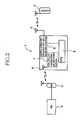
- Fig. 2 is a schematic view showing a configuration of the wireless communication apparatus 1.
- the wireless communication apparatus 1 is constituted by, in addition to the digital cordless antenna portion 4 and the wireless LAN antenna portion 5, a digital cordless (DCL) transmitting and receiving portion 6 for communicating, as a specific external communication section, with the handset 2, a wireless LAN (WLAN) transmitting and receiving portion 7 as another external communication section communicable with the external wireless LAN devices through the wireless communication using the wireless LAN system, a CPU 8 for controlling components of the wireless communication apparatus 1, and the like.
- DCL digital cordless
- WLAN wireless LAN
- the digital cordless transmitting and receiving portion 6 communicates with the handset 2 through the wireless communication.
- Fig. 1 is constituted by, in addition to the digital cordless antenna portion 4 and the wireless LAN antenna portion 5, a digital cordless (DCL) transmitting and receiving portion 6 for communicating, as a specific external communication section, with the handset 2, a wireless LAN (WLAN) transmitting and receiving portion 7 as another external communication section communic
- the wireless LAN transmitting and receiving portion 7 communicates through the wireless communication with the PCs 12 via the access points 11 respectively connected thereto.
- Fig. 3 is a view showing respective relationships between frequency bands and channels used by the wireless LAN transmitting and receiving portion 7.
- the wireless LAN system uses the 2.4 GHz frequency band which is one of specific frequency bands named as Industry Science Medical (ISM) bands.
- ISM Industry Science Medical
- the 2.4 GHz frequency band is divided into fourteen channels (i.e., frequency ranges) as communicable frequency bands each having a predetermined pitch of about 5 MHz.
- Each of the external wireless LAN devices can selectively use any one or more of the channels.
- each of the fourteen channels can be divided into a plurality of communication frequency bands. It is stipulated that a set number of communication frequency bands must be always secured in communication using the cordless phone system.
- the cordless phone communication between the wireless communication apparatus 1 and the handset 2 is performed using the set number of the communication frequency bands. More specifically, the wireless communication apparatus 1 communicates with the handset 2 through the cordless phone communication using one of the communication bands at one time while successively changing the communication frequency bands. It is noted that the set number of the communication frequency bands in each of which the digital cordless transmitting and receiving portion 6 is planned to communicate with the handset 2 may be referred to as communication planned frequency bands.
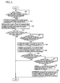
- Fig. 4 is a flow chart showing a processing of the digital cordless transmitting and receiving portion 6.
- the network identifying information includes a Service Set Identifier (SSID) that is a name for identifying the external wireless device, and the following information relating to the SSID: a frequency band being used by the external wireless device, and an electric field intensity in the frequency band, an electric field intensity to be generated by the external wireless device in the frequency band, and so on, for example.
- the wireless LAN transmitting and receiving portion 7 also functions as a communication condition recognizing section and recognizes, on the basis of the received network identifying information, a communication condition in each of the channels.
- the wireless LAN transmitting and receiving portion 7 recognizes a number of the external wireless LAN devices and the electric field intensity in each of the channels. It is noted that the electric field intensity is generated by one of the external wireless LAN devices communicating in each channel, which one is to generate the maximum electric field intensity.
- the wireless LAN transmitting and receiving portion 7 transmits, to the digital cordless transmitting and receiving portion 6, channel informations each of which is information about the communication condition in each channel.
- Each of the channel informations includes the number of the recognized external wireless LAN devices and the recognized electric field intensity in each of the channels. It is noted that, in the present embodiment, each channel information can be separated into R1 channel information, R2 channel information, and R3 channel information which will be explained below.
- the digital cordless transmitting and receiving portion 6 determines, on the basis of the channel information in each channel, the above-described communication planned frequency bands. More specifically, the wireless LAN transmitting and receiving portion 7 determines, on the basis of the number of the external wireless LAN devices and the electric field intensity in each channel, the communication planned frequency bands by allocating to a part of the communication frequency bands, such that an interference with the cordless phone communication between the wireless communication apparatus 1 and the handset 2 is minimized.
- a specific threshold intensity n1 and a specific threshold number n2 are set respectively as a specific electric field intensity and a specific number of the external wireless LAN devices, and the set number of the communication planned frequency bands are determined on the assumption that the radio interference is less likely to occur in one channel in the following order: a case in which a maximum electric field intensity in the channel is lower than the specific threshold intensity n1 and the number of the external wireless LAN devices in the channel is smaller than the specific threshold number n2 (in this case, the channel may be referred to as a low-electric-field-intensity ⁇ small-device-number range), a case in which the maximum electric field intensity in the channel is lower than the specific threshold intensity n1 and the number of the external wireless LAN devices in the channel is equal to or larger than the specific threshold number n2 (in this
- the digital cordless transmitting and receiving portion 6 judges, in S100, whether the above-described R1 channel information is transmitted from the wireless LAN transmitting and receiving portion 7.
- the R1 channel information is the above-described channel information about the channel.
- the R1 channel is a channel in which the electric field intensity in one channel is lower than the specific threshold intensity n1 and the number of the external wireless LAN devices in the channel is smaller than the specific threshold number n2. That is, where the channel is the above-described low-electric-field-intensity-small-device-number range, the channel is recognized to be the R1 channel by the wireless LAN transmitting and receiving portion 7.
- Fig. 5 is an example of a compilation of network identifying information received by the wireless LAN transmitting and receiving portion 7.
- a Received Signal Strength Indication (RSSI) is a value that indicates a strength of a signal to be received by the wireless LAN devices such as this wireless communication apparatus 1.
- RSSI Received Signal Strength Indication
- a value of each of the RSSIs indicates an electric field intensity in a frequency band used by a corresponding one of the external wireless LAN devices that respectively correspond to the SSIDs.
- the electric field intensity is shown for each of the fourteen channels used in the wireless LAN system, and each channel has the corresponding predetermined frequency range. Thus, the electric field intensity in each channel can be recognized.
- recognition that the radio interference is more likely to occur is firstly performed on the basis that the electric field intensity is relatively high in the channel, and secondly performed on the basis that the number of the external wireless LAN devices is relatively large.
- the possibility of the occurrence of the radio interference is the highest in a channel 1 (1ch) among all the channels, the second highest in a channel 13 (13ch), and the third highest in a channel 6 (6ch) or a channel 11 (11ch).
- the digital cordless transmitting and receiving portion 6 sorts, in S110, the R1 channels in ascending order of the maximum electric field intensity. Then, in S120, the digital cordless transmitting and receiving portion 6 allocates at least a part of the communication planned frequency bands to the R1 channels in ascending order of the maximum electric field intensity up to the set number.
- the digital cordless transmitting and receiving portion 6 determines, on the priority basis, the communication planned frequency bands by allocating to the R1 channels each satisfying the condition that the maximum electric field intensity in the channel is lower than the specific threshold intensity n1 and that the number of the external wireless LAN devices in the channel is smaller than the specific threshold number n2. In other words, the digital cordless transmitting and receiving portion 6 determines the communication planned frequency bands by allocating to the R1 channels in ascending order of the maximum electric field intensity in an allocation to the low-electric-field-intensity-small-device-number ranges. It is noted that where the digital cordless transmitting and receiving portion 6 has not received the R1 channel information from the wireless LAN transmitting and receiving portion 7 (S100: No), the digital cordless transmitting and receiving portion 6 waits until the reception of the R1 channel information.
- the digital cordless transmitting and receiving portion 6 judges whether all the communication planned frequency bands have been determined. Where all the communication planned frequency bands have been determined (S130: YES), the digital cordless transmitting and receiving portion 6 judges to have secured the set number of the communication planned frequency bands. Then, this processing is completed.
- the digital cordless transmitting and receiving portion 6 determines, in the following procedures, remaining at least one of the communication planned frequency bands by allocating to R2 channels which will be explained below.
- the digital cordless transmitting and receiving portion 6 judges whether the digital cordless transmitting and receiving portion 6 has received, from the wireless LAN transmitting and receiving portion 7, the above-described R2 channel information.
- the R2 channel information is the above-described channel information about the channel.
- the R2 channel is a channel in which the electric field intensity in one channel is lower than the specific threshold intensity n1 and the number of the external wireless LAN devices in the channel is larger than the specific threshold number n2. That is, where the channel is the above-described low-electric-field-intensity ⁇ large-device-number range, the channel is recognized to be the R2 channel by the wireless LAN transmitting and receiving portion 7.
- the digital cordless transmitting and receiving portion 6 sorts, in S150, the R2 channels in ascending order of the number of the external wireless LAN devices. Where the digital cordless transmitting and receiving portion 6 has not received the R2 channel information from the wireless LAN transmitting and receiving portion 7 (S140: NO), the digital cordless transmitting and receiving portion 6 waits until the reception of the R2 channel information.
- the digital cordless transmitting and receiving portion 6 which has sorted the R2 channels in S150 determines, in S160, remaining at least one of the communication planned frequency bands by allocating to the R2 channels in ascending order of the number of the external wireless LAN devices up to the set number. That is, in S150 and S160, the digital cordless transmitting and receiving portion 6 determines, on the priority basis, the remaining at least one of the communication planned frequency band by allocating to the R2 channels each satisfying the condition that the maximum electric field intensity in the channel is lower than the specific threshold intensity n1 and that the number of the external wireless LAN devices in the channel is equal to or larger than the specific threshold number n2.
- the digital cordless transmitting and receiving portion 6 determines the remaining at least one of the communication planned frequency bands by allocating to the R2 channels in ascending order of the number of the external wireless LAN devices in an allocation to the low-electric-field -intensity ⁇ large-device-number ranges.
- the digital cordless transmitting and receiving portion 6 judges whether all the communication planned frequency bands have been determined. Where all the communication planned frequency bands have been determined (S165: YES), the digital cordless transmitting and receiving portion 6 judges to have secured the set number of the communication planned frequency bands. Then, this processing is completed. That is, in S100 to S165, the digital cordless transmitting and receiving portion 6 determines the communication planned frequency bands by allocating, on the priority basis, to low-electric-field-intensity ranges of the frequency ranges in each of which the electric field intensity is lower than the specific threshold intensity n1.
- the digital cordless transmitting and receiving portion 6 determines remaining at least one of the communication planned frequency bands by allocating to remaining channels in ascending order of the number of the external wireless LAN devices in the following procedures.
- the digital cordless transmitting and receiving portion 6 judges whether the digital cordless transmitting and receiving portion 6 has received, from the wireless LAN transmitting and receiving portion 7, the above-described R3 channel information.
- the R3 channel information is the above-described channel information about the channel.
- the R3 channel is a channel in which the electric field intensity in one channel is equal to or higher than the specific threshold intensity n1. That is, where the channel is the above-described high-electric-field-intensity range, the channel is recognized to be the R2 channel by the wireless LAN transmitting and receiving portion 7.
- the digital cordless transmitting and receiving portion 6 sorts, in S180, the R3 channels in ascending order of the number of the external wireless LAN devices. Where the digital cordless transmitting and receiving portion 6 has not received the R3 channel information from the wireless LAN transmitting and receiving portion 7 (S170: NO), the digital cordless transmitting and receiving portion 6 waits until a reception of the R3 channel information.
- the digital cordless transmitting and receiving portion 6 which has sorted the R3 channels in S180 determines, in S190, remaining at least one of the communication planned frequency bands by allocating to the R3 channels in ascending order of the number of the external wireless LAN devices. That is, in S180 and S190, the digital cordless transmitting and receiving portion 6 determines remaining at least one of the communication planned frequency bands by allocating to the R3 channels each satisfying the condition that the maximum electric field intensity in the channel is equal to or higher than the specific threshold intensity n1.
- the digital cordless transmitting and receiving portion 6 determines the remaining at least one of the communication planned frequency bands by allocating to the R3 channels in ascending order of the number of the external wireless LAN devices in an allocation to high-electric-field-intensity ranges.
- the digital cordless transmitting and receiving portion 6 can determine the remaining at least one of the communication planned frequency bands by allocating to the R3 channels in ascending order of the possibility of the occurrence of the radio interference.
- the digital cordless transmitting and receiving portion 6 judges to have secured the set number of the communication planned frequency bands. Then, this processing is completed.
- the digital cordless transmitting and receiving portion 6 determines the communication planned frequency bands by allocating to ones of the frequency ranges in ascending order of the electric field intensity. Further, generally, in the above-explained procedures, the digital cordless transmitting and receiving portion 6 determines the communication planned frequency bands by allocating to ones of the frequency ranges in ascending order of the number of the communicating communication devices.
- the digital cordless transmitting and receiving portion 6 communicates with the handset 2 through the wireless communication while successively changing among the communication planned frequency bands determined in the above-described processing. That is, the digital cordless transmitting and receiving portion 6 communicates with the handset 2 through the wireless communication using a frequency hopping in the communication planned frequency bands determined in the above-described processing. As a result, a good quality of the cordless phone communication between the wireless communication apparatus 1 and the handset 2 is ensured.
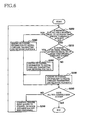
- Fig. 6 is a flow chart showing a processing of the wireless LAN transmitting and receiving portion 7.
- the wireless LAN transmitting and receiving portion 7 receives the network identifying information from each of the access points 11. On the basis of the received network identifying information, the wireless LAN transmitting and receiving portion 7 recognizes the maximum electric field intensity in each channel, and sends the R1, R2, R3 channel informations to the digital cordless transmitting and receiving portion 6. Since the received network identifying information is compiled for each of the channels which can be used by the wireless communication apparatus 1 through the wireless communication using the wireless LAN system, the wireless LAN transmitting and receiving portion 7 can recognize the communication condition in each channel which can be used by the wireless communication apparatus 1 and the maximum electric field intensity in the channel without a complex recognition of the frequency bands.
- the wireless LAN transmitting and receiving portion 7 judges whether the maximum electric field intensity in a channel being judged is equal to or higher than the specific threshold intensity n1. Where the maximum electric field intensity is equal to or higher than the specific threshold intensity n1 (S200: YES), the wireless LAN transmitting and receiving portion 7 sends, in S240, to the digital cordless transmitting and receiving portion 6, the R3 channel information representing that the maximum electric field intensity is equal to or higher than the specific threshold intensity n1 in the channel being judged. Then, in S230, the wireless LAN transmitting and receiving portion 7 judges whether all the channels have been judged.
- the wireless LAN transmitting and receiving portion 7 completes this processing on the assumption that each of the channel data has been transmitted.
- the wireless LAN transmitting and receiving portion 7 changes, in S260, the channel being judged to a channel on which the judgment has not been performed. Then, the processing goes back to S200, and the judgment is performed on a new channel.
- the wireless LAN transmitting and receiving portion 7 judges, in S210, whether the number of the external wireless LAN devices in the channel being judged is equal to or larger than the specific threshold number n2. Where the number of the external wireless LAN devices is equal to or larger than the specific threshold number n2 (S210: YES), the wireless LAN transmitting and receiving portion 7 sends, in S250, to the digital cordless transmitting and receiving portion 6, the R2 channel information representing that the maximum electric field intensity is lower than the specific threshold intensity n1 and the number of the external wireless LAN devices is equal to or larger than the specific threshold number n2 in the channel being judged. Then, the processing goes to S230 in which the wireless LAN transmitting and receiving portion 7 judges whether this processing has been performed on all the channels.
- the wireless LAN transmitting and receiving portion 7 sends, in S220, to the digital cordless transmitting and receiving portion 6, the R1 channel information representing that the maximum electric field intensity is lower than the specific threshold intensity n1 and the number of the external wireless LAN devices is smaller than the specific threshold number n2 in the channel being judged. Then, the processing goes to S230 in which the wireless LAN transmitting and receiving portion 7 judges whether all the channels have been judged.
- the wireless LAN transmitting and receiving portion 7 can send all the channel data to the digital cordless transmitting and receiving portion 6 by performing this processing.
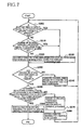
- Fig. 7 is a flow chart showing a processing of a digital cordless transmitting and receiving portion 6 of the wireless communication apparatus 1 as a modification of the embodiment.
- This wireless communication apparatus 1 differs from the above-described wireless communication apparatus 1 in that at least one of the specific threshold intensity n1 and the specific threshold number n2 is variable.
- the at least one of the specific threshold intensity n1 and the specific threshold number n2 is variable, there can be reduced, for example, a possibility that one or ones of the communication planned frequency bands is or are allocated to a channel in which a plurality of the external wireless LAN devices each having a possibility of generating a maximum electric field intensity slightly lower than the threshold value n1 are present, prior to a channel in which one external wireless LAN device having a possibility of generating a maximum electric field intensity slightly higher than the threshold value n1 is present.
- this wireless communication apparatus 1 can determine the communication planned frequency bands in each of which a communication condition is relatively good. It is noted that components of this modification other than the digital cordless transmitting and receiving portion 6 and a wireless LAN transmitting and receiving portion 7 are identical with those of the above-described embodiment, and description thereof is dispensed with.
- the digital cordless transmitting and receiving portion 6 judges, on the basis of the above-explained channel data received from the wireless LAN transmitting and receiving portion 7, whether the electric field intensity in a channel being judged is equal to or higher than the specific threshold intensity n1. Where the electric field intensity in the channel being judged is lower than the specific threshold intensity n1 (S300: NO), the digital cordless transmitting and receiving portion 6 judges, in S310, whether the above-described number of the external wireless LAN devices in the channel being judged is equal to or larger than the specific threshold number n2.
- the digital cordless transmitting and receiving portion 6 inhibits, in S330, the channel from being used for the wireless communication between the wireless communication apparatus 1 and the handset 2. That is, the digital cordless transmitting and receiving portion 6 inhibits the allocation of the communication planned frequency bands. More specifically, the digital cordless transmitting and receiving portion 6 inhibits the allocation of the communication planned frequency bands to the high-electric-field-intensity range.
- the digital cordless transmitting and receiving portion 6 allows, in S320, the channel to be used for the wireless communication between the wireless communication apparatus 1 and the handset 2. That is, the digital cordless transmitting and receiving portion 6 allows the allocation of the communication planned frequency bands. More specifically, the digital cordless transmitting and receiving portion 6 allows the allocation of the communication planned frequency bands to the low-electric-field-intensity-small-device-number range.
- the digital cordless transmitting and receiving portion 6 inhibits, in S330, the channel from being used for the wireless communication between the wireless communication apparatus 1 and the handset 2. That is, the digital cordless transmitting and receiving portion 6 inhibits the allocation of the communication planned frequency bands. More specifically, the digital cordless transmitting and receiving portion 6 inhibits the allocation of the communication planned frequency bands to the low-electric-field-intensity-small-device-number range.
- the digital cordless transmitting and receiving portion 6 judges whether the procedure of S300 has been performed on all the channels. Where the procedure of S300 has not been performed on all the channels (S340: NO), the digital cordless transmitting and receiving portion 6 changes, in S345, the channel being judged to a channel on which the judgment has not been performed. Then, the processing goes back to S300, and the judgment is performed on a new channel.
- the digital cordless transmitting and receiving portion 6 judges, in S350, whether the number of the channels allowed in S320 is equal to or larger than a number of the channels required for the allocation of all the communication planned frequency bands. Where the number of the channels allowed in S320 is equal to or larger than the number required for the allocation of all the communication planned frequency bands (S350: YES), the digital cordless transmitting and receiving portion 6 determines the set number of the communication planned frequency bands by allocating to the allowed channels. Then, the digital cordless transmitting and receiving portion 6 subtracts, in S360, a specific value or specific values from at least one of the specific threshold intensity n1 and the specific threshold number n2.
- the at least one of the specific threshold intensity n1 and the specific threshold number n2 is decreased by at least one of decreasing the specific threshold intensity n1 by a specific decrease amount and decreasing the specific threshold number n2 by a specific decrease number. Then, this processing is completed.
- the subtraction from the at least one of the specific threshold intensity n1 and the specific threshold number n2 tightens a criterion of the judgment.
- the digital cordless transmitting and receiving portion 6 adds, in S370, a specific value or specific values to at least one of the specific threshold intensity n1 and the specific threshold number n2. That is, the at least one of the specific threshold intensity n1 and the specific threshold number n2 is increased by at least one of increasing the specific threshold intensity n1 by a specific increase amount and increasing the specific threshold number n2 by a specific increase number.
- the digital cordless transmitting and receiving portion 6 sets, to channels to be judged, the channels inhibited, in S330, from being used. Then, the processing goes back to S300, and the digital cordless transmitting and receiving portion 6 performs the judgment with new threshold values. That is, the digital cordless transmitting and receiving portion 6 redetermines the communication planned frequency bands by reallocating to the low-electric-field-intensity ⁇ small-device-number ranges. The addition to the at least one of the specific threshold intensity n1 and the specific threshold number n2 loosens the criterion of the judgment. Thus, one or ones of the inhibited channels in each of which the communication condition is relatively good can be additionally allowed to be used to secure the set number of the communication planned frequency bands.
- the digital cordless transmitting and receiving portion 6 determines the communication planned frequency bands by allocating to ones of the frequency ranges in ascending order of the electric field intensity. In other words, the digital cordless transmitting and receiving portion 6 determines the communication planned frequency bands by allocating while excluding ones of the frequency ranges in descending order of the electric field intensity. As a result, even where a number of the inhibited channels is larger than the number of the channels required for the allocation of the communication planned frequency bands, the radio interference can be effectively prevented.
- the digital cordless transmitting and receiving portion 6 determines the communication planned frequency bands by allocating to ones of the frequency ranges in ascending order of the number of the external wireless LAN devices. In other words, the digital cordless transmitting and receiving portion 6 determines the communication planned frequency bands by allocating while excluding ones of the frequency ranges in descending order of the number of the external wireless LAN devices.
- the radio interference can be effectively prevented by decreasing the number of the external wireless LAN devices each having the possibility of the occurrence of the radio interference.
- the digital cordless transmitting and receiving portion 6 subtracts or adds specific values to or from both of the specific threshold intensity n1 and the specific threshold number n2 to properly adjust the specific threshold intensity n1 and the specific threshold number n2.
- the set number of the communication planned frequency bands are determined by the digital cordless transmitting and receiving portion 6 of the wireless communication apparatus 1 as the modification of the above-described embodiment.
- Fig. 8 is a flow chart showing a processing of the wireless LAN transmitting and receiving portion 7 of the wireless communication apparatus 1 as the modification of the above-described embodiment.
- the wireless LAN transmitting and receiving portion 7 judges whether the communication conditions about all the channels have been recognized. Where the communication conditions about all the channels have been recognized (S400: YES), the wireless LAN transmitting and receiving portion 7 sends, in S410, one of the communication conditions which is last recognized, to the digital cordless transmitting and receiving portion 6.
- the wireless LAN transmitting and receiving portion 7 sends, in S420, a communication condition about the channel being judged, to the digital cordless transmitting and receiving portion 6. Then, in S430, the wireless LAN transmitting and receiving portion 7 changes the channel being judged to one of remaining channels which have not been judged, and the processing goes back to S400.
- the communication conditions about all the channel are sent to the digital cordless transmitting and receiving portion 6 by the wireless LAN transmitting and receiving portion 7 of the wireless communication apparatus 1 as the modification of the above-described embodiment.
Landscapes
- Engineering & Computer Science (AREA)
- Computer Networks & Wireless Communication (AREA)
- Signal Processing (AREA)
- Mobile Radio Communication Systems (AREA)
- Small-Scale Networks (AREA)
- Transceivers (AREA)
- Transmitters (AREA)
Applications Claiming Priority (1)
| Application Number | Priority Date | Filing Date | Title |
|---|---|---|---|
| JP2007091610A JP4491796B2 (ja) | 2007-03-30 | 2007-03-30 | 無線装置 |
Publications (3)
| Publication Number | Publication Date |
|---|---|
| EP1978679A2 true EP1978679A2 (de) | 2008-10-08 |
| EP1978679A3 EP1978679A3 (de) | 2010-03-10 |
| EP1978679B1 EP1978679B1 (de) | 2011-05-11 |
Family
ID=39708925
Family Applications (1)
| Application Number | Title | Priority Date | Filing Date |
|---|---|---|---|
| EP08251084A Ceased EP1978679B1 (de) | 2007-03-30 | 2008-03-26 | Vorrichtung zur drahtlosen Kommunikation |
Country Status (3)
| Country | Link |
|---|---|
| US (1) | US8040816B2 (de) |
| EP (1) | EP1978679B1 (de) |
| JP (1) | JP4491796B2 (de) |
Families Citing this family (8)
| Publication number | Priority date | Publication date | Assignee | Title |
|---|---|---|---|---|
| US20100022237A1 (en) * | 2008-07-28 | 2010-01-28 | At&T Intellectual Property I, L.P. | Multi-mode communication system |
| JP4924626B2 (ja) * | 2009-01-30 | 2012-04-25 | ブラザー工業株式会社 | 無線通信装置 |
| JP4978630B2 (ja) * | 2009-01-30 | 2012-07-18 | ブラザー工業株式会社 | 無線通信装置、および無線通信制御方法 |
| US20130094386A1 (en) * | 2010-06-18 | 2013-04-18 | Panasonic Corporation | Communication terminal device and communication method |
| EP2521389A2 (de) | 2010-09-20 | 2012-11-07 | LG Electronics Inc. | Verfahren und vorrichtung zur deaktivierung einer illegalen vorrichtung in einem drahtlosen lan-system |
| KR20120076287A (ko) * | 2010-12-29 | 2012-07-09 | 한국전자통신연구원 | 다수의 주파수 공유장치간 상호공존을 위한 상호공존 관리 시스템의 프로시져 및 메시지 |
| US10917164B2 (en) * | 2016-11-10 | 2021-02-09 | Cable Television Laboratories, Inc. | Systems and methods for ultra reliable low latency communications |
| JP2024505582A (ja) * | 2021-02-03 | 2024-02-06 | グーグル エルエルシー | 電磁伝播における不等式の迅速な評価 |
Citations (3)
| Publication number | Priority date | Publication date | Assignee | Title |
|---|---|---|---|---|
| JP2002198867A (ja) | 2000-12-27 | 2002-07-12 | Toshiba Corp | 無線通信方法および無線通信装置 |
| JP2002198868A (ja) | 2000-12-27 | 2002-07-12 | Toshiba Corp | 無線通信方法および無線通信装置 |
| JP2007091610A (ja) | 2005-09-27 | 2007-04-12 | Kenichi Ochi | 柑橘エキスうがい液 |
Family Cites Families (16)
| Publication number | Priority date | Publication date | Assignee | Title |
|---|---|---|---|---|
| JPH1042353A (ja) * | 1996-07-22 | 1998-02-13 | Matsushita Electric Ind Co Ltd | 無線通信システム |
| US6009332A (en) * | 1996-08-28 | 1999-12-28 | Telefonaktiebolaget Lm Ericsson | Method and system for autonomously allocating a frequency hopping traffic channel in a private radio system |
| EP1111947A1 (de) | 1999-12-22 | 2001-06-27 | Telefonaktiebolaget L M Ericsson (Publ) | Schnurloses Telefonsystem |
| CN1254992C (zh) * | 1999-12-22 | 2006-05-03 | 诺基亚有限公司 | 跳频扩频通信系统 |
| JP2002095062A (ja) * | 2000-09-20 | 2002-03-29 | Canon Inc | 通信システム |
| JP2003023674A (ja) * | 2001-07-10 | 2003-01-24 | Victor Co Of Japan Ltd | 電話システム |
| JP4287604B2 (ja) * | 2001-08-27 | 2009-07-01 | 富士通株式会社 | 移動体通信システム並びに無線基地局,無線装置及び移動端末 |
| JP4122789B2 (ja) * | 2002-02-13 | 2008-07-23 | 日本電気株式会社 | 複合無線装置及びそれに用いる干渉回避制御方法 |
| GB2385747B (en) * | 2002-02-21 | 2004-04-28 | Toshiba Res Europ Ltd | Channel management in adaptive hopping schemes |
| JP2003249973A (ja) * | 2002-02-22 | 2003-09-05 | Sharp Corp | 通信システム、通信制御装置および通信端末装置 |
| JP2004159053A (ja) * | 2002-11-06 | 2004-06-03 | Matsushita Electric Ind Co Ltd | 電話装置 |
| CN100405769C (zh) * | 2003-03-10 | 2008-07-23 | 巴比禄股份有限公司 | 接入点 |
| JP2004363728A (ja) * | 2003-06-02 | 2004-12-24 | Canon Inc | 無線情報通信端末 |
| JP4702738B2 (ja) * | 2005-03-16 | 2011-06-15 | 株式会社ソニー・コンピュータエンタテインメント | ゲームシステム |
| US7697896B2 (en) * | 2005-03-16 | 2010-04-13 | Sony Computer Entertainment Inc. | Communication apparatus preventing communication interference |
| US7558592B2 (en) * | 2005-09-01 | 2009-07-07 | Cisco Technology, Inc. | Radio planning for WLANS |
-
2007
- 2007-03-30 JP JP2007091610A patent/JP4491796B2/ja active Active
-
2008
- 2008-03-25 US US12/055,287 patent/US8040816B2/en not_active Expired - Fee Related
- 2008-03-26 EP EP08251084A patent/EP1978679B1/de not_active Ceased
Patent Citations (3)
| Publication number | Priority date | Publication date | Assignee | Title |
|---|---|---|---|---|
| JP2002198867A (ja) | 2000-12-27 | 2002-07-12 | Toshiba Corp | 無線通信方法および無線通信装置 |
| JP2002198868A (ja) | 2000-12-27 | 2002-07-12 | Toshiba Corp | 無線通信方法および無線通信装置 |
| JP2007091610A (ja) | 2005-09-27 | 2007-04-12 | Kenichi Ochi | 柑橘エキスうがい液 |
Also Published As
| Publication number | Publication date |
|---|---|
| EP1978679A3 (de) | 2010-03-10 |
| US8040816B2 (en) | 2011-10-18 |
| US20080240066A1 (en) | 2008-10-02 |
| JP4491796B2 (ja) | 2010-06-30 |
| EP1978679B1 (de) | 2011-05-11 |
| JP2008252554A (ja) | 2008-10-16 |
Similar Documents
| Publication | Publication Date | Title |
|---|---|---|
| EP1978679B1 (de) | Vorrichtung zur drahtlosen Kommunikation | |
| US9681463B2 (en) | Coexistence priority selection | |
| US6882849B2 (en) | Wireless user equipment for use in reducing cross cell interference | |
| CN104022797B (zh) | 半导体装置 | |
| JP4168016B2 (ja) | 無線通信システムにおけるチャンネル割当装置及び方法 | |
| US7181657B2 (en) | Data transmission apparatus adaptive to data quality on radio-transmission and a method of data transmission therefor | |
| JP5036760B2 (ja) | 無線通信装置および帯域制御方法 | |
| US20060073827A1 (en) | System and handover mechanism in frequency multilple band environment and equipment therefor | |
| EP2408137A2 (de) | Dynamische Interferenzsteuerung in einem drahtlosen Kommunikationsnetzwerk | |
| CN100433870C (zh) | 无线通信设备和无线通信方法 | |
| WO2007052811A1 (ja) | 複数の信号帯域幅を定義する無線通信システムにおける送受信帯域幅設定方法、移動端末および基地局 | |
| US20050220135A1 (en) | Wireless communication method and wireless communication device | |
| CN100393159C (zh) | 实现通信系统共存的设备和方法 | |
| JP4812532B2 (ja) | 移動局装置および基地局装置並びに下りリソース割り当て方法 | |
| CN103841631B (zh) | 一种基于自干扰消除技术的通信方法、基站及通信系统 | |
| JPWO2010061614A1 (ja) | 空間多重スロット割当方法および基地局 | |
| KR20150123073A (ko) | 주파수 공유대역에서 가용채널 확보를 위해 우선 채널을 할당하는 네트워크 관리 장치 및 그 방법 | |
| KR100652577B1 (ko) | 복수의 무선 통신 기능을 구비한 장치의 통신 방법 | |
| AU2024363009A1 (en) | Communication device, control method, and program | |
| JPS62226729A (ja) | 送信権制御方法 | |
| JPH07245780A (ja) | 制御チャネル設定方法 | |
| JP2009033647A (ja) | 通信装置および通信方法 | |
| JP2006253832A (ja) | 無線基地局システム、送信選択方法および送信選択プログラム |
Legal Events
| Date | Code | Title | Description |
|---|---|---|---|
| PUAI | Public reference made under article 153(3) epc to a published international application that has entered the european phase |
Free format text: ORIGINAL CODE: 0009012 |
|
| AK | Designated contracting states |
Kind code of ref document: A2 Designated state(s): AT BE BG CH CY CZ DE DK EE ES FI FR GB GR HR HU IE IS IT LI LT LU LV MC MT NL NO PL PT RO SE SI SK TR |
|
| AX | Request for extension of the european patent |
Extension state: AL BA MK RS |
|
| PUAL | Search report despatched |
Free format text: ORIGINAL CODE: 0009013 |
|
| AK | Designated contracting states |
Kind code of ref document: A3 Designated state(s): AT BE BG CH CY CZ DE DK EE ES FI FR GB GR HR HU IE IS IT LI LT LU LV MC MT NL NO PL PT RO SE SI SK TR |
|
| AX | Request for extension of the european patent |
Extension state: AL BA MK RS |
|
| 17P | Request for examination filed |
Effective date: 20100723 |
|
| RIC1 | Information provided on ipc code assigned before grant |
Ipc: H04W 72/12 20090101AFI20100824BHEP |
|
| AKX | Designation fees paid |
Designated state(s): DE FR GB |
|
| GRAP | Despatch of communication of intention to grant a patent |
Free format text: ORIGINAL CODE: EPIDOSNIGR1 |
|
| GRAS | Grant fee paid |
Free format text: ORIGINAL CODE: EPIDOSNIGR3 |
|
| GRAA | (expected) grant |
Free format text: ORIGINAL CODE: 0009210 |
|
| AK | Designated contracting states |
Kind code of ref document: B1 Designated state(s): DE FR GB |
|
| REG | Reference to a national code |
Ref country code: GB Ref legal event code: FG4D |
|
| REG | Reference to a national code |
Ref country code: DE Ref legal event code: R096 Ref document number: 602008006794 Country of ref document: DE Effective date: 20110622 |
|
| PLBE | No opposition filed within time limit |
Free format text: ORIGINAL CODE: 0009261 |
|
| STAA | Information on the status of an ep patent application or granted ep patent |
Free format text: STATUS: NO OPPOSITION FILED WITHIN TIME LIMIT |
|
| 26N | No opposition filed |
Effective date: 20120214 |
|
| REG | Reference to a national code |
Ref country code: DE Ref legal event code: R097 Ref document number: 602008006794 Country of ref document: DE Effective date: 20120214 |
|
| REG | Reference to a national code |
Ref country code: FR Ref legal event code: PLFP Year of fee payment: 9 |
|
| REG | Reference to a national code |
Ref country code: FR Ref legal event code: PLFP Year of fee payment: 10 |
|
| REG | Reference to a national code |
Ref country code: FR Ref legal event code: PLFP Year of fee payment: 11 |
|
| PGFP | Annual fee paid to national office [announced via postgrant information from national office to epo] |
Ref country code: GB Payment date: 20180223 Year of fee payment: 11 |
|
| PGFP | Annual fee paid to national office [announced via postgrant information from national office to epo] |
Ref country code: FR Payment date: 20180223 Year of fee payment: 11 |
|
| PGFP | Annual fee paid to national office [announced via postgrant information from national office to epo] |
Ref country code: DE Payment date: 20190215 Year of fee payment: 12 |
|
| GBPC | Gb: european patent ceased through non-payment of renewal fee |
Effective date: 20190326 |
|
| PG25 | Lapsed in a contracting state [announced via postgrant information from national office to epo] |
Ref country code: GB Free format text: LAPSE BECAUSE OF NON-PAYMENT OF DUE FEES Effective date: 20190326 |
|
| PG25 | Lapsed in a contracting state [announced via postgrant information from national office to epo] |
Ref country code: FR Free format text: LAPSE BECAUSE OF NON-PAYMENT OF DUE FEES Effective date: 20190331 |
|
| REG | Reference to a national code |
Ref country code: DE Ref legal event code: R119 Ref document number: 602008006794 Country of ref document: DE |
|
| PG25 | Lapsed in a contracting state [announced via postgrant information from national office to epo] |
Ref country code: DE Free format text: LAPSE BECAUSE OF NON-PAYMENT OF DUE FEES Effective date: 20201001 |