EP1978534B1 - Tastatur für ein Haushaltgerät und Verfahren für deren Einbau - Google Patents
Tastatur für ein Haushaltgerät und Verfahren für deren Einbau Download PDFInfo
- Publication number
- EP1978534B1 EP1978534B1 EP08102700A EP08102700A EP1978534B1 EP 1978534 B1 EP1978534 B1 EP 1978534B1 EP 08102700 A EP08102700 A EP 08102700A EP 08102700 A EP08102700 A EP 08102700A EP 1978534 B1 EP1978534 B1 EP 1978534B1
- Authority
- EP
- European Patent Office
- Prior art keywords
- button
- frame
- keyboard
- blocking
- control element
- Prior art date
- Legal status (The legal status is an assumption and is not a legal conclusion. Google has not performed a legal analysis and makes no representation as to the accuracy of the status listed.)
- Not-in-force
Links
- 238000000034 method Methods 0.000 title claims abstract description 13
- 238000009434 installation Methods 0.000 title 1
- 230000000903 blocking effect Effects 0.000 claims description 51
- 238000002844 melting Methods 0.000 claims description 7
- 230000008018 melting Effects 0.000 claims description 7
- 238000006073 displacement reaction Methods 0.000 claims description 5
- 229920003023 plastic Polymers 0.000 claims description 4
- 239000004033 plastic Substances 0.000 claims description 4
- 239000000463 material Substances 0.000 claims description 2
- 238000003466 welding Methods 0.000 description 21
- 238000004519 manufacturing process Methods 0.000 description 6
- 238000004026 adhesive bonding Methods 0.000 description 4
- 238000005266 casting Methods 0.000 description 3
- 238000010438 heat treatment Methods 0.000 description 2
- 238000001514 detection method Methods 0.000 description 1
- 230000000694 effects Effects 0.000 description 1
- 239000000155 melt Substances 0.000 description 1
- 238000010309 melting process Methods 0.000 description 1
- 239000007787 solid Substances 0.000 description 1
- 230000000007 visual effect Effects 0.000 description 1
Images

Classifications
-
- H—ELECTRICITY
- H01—ELECTRIC ELEMENTS
- H01H—ELECTRIC SWITCHES; RELAYS; SELECTORS; EMERGENCY PROTECTIVE DEVICES
- H01H13/00—Switches having rectilinearly-movable operating part or parts adapted for pushing or pulling in one direction only, e.g. push-button switch
- H01H13/70—Switches having rectilinearly-movable operating part or parts adapted for pushing or pulling in one direction only, e.g. push-button switch having a plurality of operating members associated with different sets of contacts, e.g. keyboard
- H01H13/702—Switches having rectilinearly-movable operating part or parts adapted for pushing or pulling in one direction only, e.g. push-button switch having a plurality of operating members associated with different sets of contacts, e.g. keyboard with contacts carried by or formed from layers in a multilayer structure, e.g. membrane switches
- H01H13/705—Switches having rectilinearly-movable operating part or parts adapted for pushing or pulling in one direction only, e.g. push-button switch having a plurality of operating members associated with different sets of contacts, e.g. keyboard with contacts carried by or formed from layers in a multilayer structure, e.g. membrane switches characterised by construction, mounting or arrangement of operating parts, e.g. push-buttons or keys
-
- H—ELECTRICITY
- H02—GENERATION; CONVERSION OR DISTRIBUTION OF ELECTRIC POWER
- H02B—BOARDS, SUBSTATIONS OR SWITCHING ARRANGEMENTS FOR THE SUPPLY OR DISTRIBUTION OF ELECTRIC POWER
- H02B1/00—Frameworks, boards, panels, desks, casings; Details of substations or switching arrangements
- H02B1/015—Boards, panels, desks; Parts thereof or accessories therefor
- H02B1/04—Mounting thereon of switches or of other devices in general, the switch or device having, or being without, casing
- H02B1/044—Mounting through openings
-
- H—ELECTRICITY
- H01—ELECTRIC ELEMENTS
- H01H—ELECTRIC SWITCHES; RELAYS; SELECTORS; EMERGENCY PROTECTIVE DEVICES
- H01H13/00—Switches having rectilinearly-movable operating part or parts adapted for pushing or pulling in one direction only, e.g. push-button switch
- H01H13/02—Details
- H01H13/12—Movable parts; Contacts mounted thereon
- H01H13/14—Operating parts, e.g. push-button
-
- H—ELECTRICITY
- H01—ELECTRIC ELEMENTS
- H01H—ELECTRIC SWITCHES; RELAYS; SELECTORS; EMERGENCY PROTECTIVE DEVICES
- H01H11/00—Apparatus or processes specially adapted for the manufacture of electric switches
- H01H2011/0093—Standardization, e.g. limiting the factory stock by limiting the number of unique, i.e. different components
-
- H—ELECTRICITY
- H01—ELECTRIC ELEMENTS
- H01H—ELECTRIC SWITCHES; RELAYS; SELECTORS; EMERGENCY PROTECTIVE DEVICES
- H01H2217/00—Facilitation of operation; Human engineering
- H01H2217/022—Part of keyboard not operable
-
- H—ELECTRICITY
- H01—ELECTRIC ELEMENTS
- H01H—ELECTRIC SWITCHES; RELAYS; SELECTORS; EMERGENCY PROTECTIVE DEVICES
- H01H2231/00—Applications
- H01H2231/012—Household appliance
Definitions
- the present invention relates to a keyboard for a device, in particular a household appliance, with at least one control element which is arranged in a predetermined position of the control.
- the keyboard has at least one button suitable for operating the control, a frame in which the button is slidably provided in a predetermined position of the button, and a blocking element.
- the invention relates to a method for installing the keyboard in household appliances.
- buttons are arranged on the front.
- the buttons can u.a. be in the style of push, turn, tilt and slide buttons.
- the high-end area has a higher number of functions and controls, ultimately operating buttons of the controls, on than the household appliances of the lower-priced area.
- buttons are part of a keyboard that is built into the device.
- This same front of the control panel can be used for a home appliance of the lowest quality range with a smaller number of controls and consequently a lower number of functionalities of the device. Therefore, this lowest quality device will have fewer buttons to operate the controls.
- keyboards that are designed for a household appliance.
- the keyboards each have at least one control that is arranged in a predetermined position.
- the keyboard includes a button configured to operate the control.
- a frame is provided in which the button is slidably providable in a predetermined position of the button.
- each locking elements are optional for permanently locking the displaceability of the button in a state in which the keyboard is attached to a device and the position of the control and the position of the button must be different or a function of the control by means of the button must be excluded known.
- a blocking element may be provided which permanently allows for the displaceability of the button in a state in which the keyboard is attached to the device and the position of the control and the position of the button correspond to each other and a function of the control by means of the button must, is trained.
- the object of the invention is therefore to provide a keyboard for a device with greater versatility, ease of assembly into the device and with lower financial costs than the keyboards of the current state of the art and a method.
- this object is achieved by a keyboard according to claim 1.
- the same keyboard can be installed in different devices, depending on the need to activate a control of the device or have a control activated by the button without another element for closing the opening created by the button. to use.
- the blocking element blocks the movement of the button and thus the same button on the keyboard takes over the capping function to close the opening of the button or in the event that the control is activated, the blocking element is not activated and allows the movement of the knob to its adjustment free space.
- the blocking element can be made effective in any manner, for example, by gluing, by clamping, by vibration welding, casting welding, heating element welding, ultrasonic welding and / or tightening.
- the button is a button that is selected from a group of buttons, with: Push buttons, push buttons, and knobs because a keyboard in a device may have one or more of these button types that may or may not be locked because they do not trigger a control.
- the button is rotatably mounted in the frame, which gives it a support point with respect to the frame of the keyboard and its actuating movement is thus a rotation with respect to a rotation axis of the frame.
- the frame has a frame edge and the button has a button support projection which can rest on the frame edge in a rest position of the button to receive the button in the frame. This ensures a rest position of the button in the frame and that it does not pick up any unwanted movements relative to the frame.
- the frame includes a frame window to lock a control display.
- a control display For example, in the event that the control is to display its functional state or any other information, this may be done by means of the display, which is locked, mounted or attached in any manner, by gluing, by vibration welding, casting welding, hot plate welding, Ultrasonic welding and / or screwing to a frame window of any geometric shape, which consists of one piece or is connected to the frame.
- the blocking element is disposed in the frame and / or in the button. In a manner in which one is connected to the other, or where the relative displacement between the two is prevented, so that the button does not move, even if it should be pressed by the user.
- the blocking element is arranged on the frame back side and / or the back side of the button, being directed towards the interior of the device and being invisible to the user.
- the locking element is arranged on the opposite side of a knob rotation axis, wherein the rotation is blocked around the axis.
- the blocking element is an integral fusible part of the frame and / or the button. This embodiment allows the inclusion of the blocking element in the frame and / or button, wherein the number of parts is reduced.
- the melt shape of the blocking element may be, among others, vibration welding, casting welding, heating element welding, ultrasonic welding.
- the blocking element extends in a molten state on the back of the button and on the back of the frame. Thus, the movement is blocked by the melting of the one-piece fusible part of the frame and / or the button with a light and fast locking system.
- the blocking element has a locking piece. It is a piece that does not belong to the frame and / or knob that can realize blocking the relative movement of the knob.
- the locking piece is a frame-shaped locking piece, which is connectable to the frame window.
- the connection between the two can be made in any manner, such as gluing, stapling, vibration welding, curtain welding, hot plate welding, ultrasonic welding, screwing, the opening of both preferably having the same size to allow visual detection of the control information via the display of the control is possible.
- the frame-shaped locking piece has at least one locking piece portion which protrudes from a locking piece edge of the frame-shaped locking piece to rest on a button support projection, whereby a button displacement distance is locked. Since the locking piece is locked on the frame window, the locking piece portion directly prevents the movement of the button.
- the blocking element extends in a molten state on the Sperr Swiss Wegseite. It is a quick way to block the path of movement of the button by melting the blocking element, connecting it to the back of the button.
- the button and / or the frame and / or the blocking element are made of plastic. It is particularly advantageous for the manufacture of this type of keyboards and for blocking the button by a fusible blocking element, because the melting of the plastic can be carried out at relatively low temperatures and thereby a very reliable blocking is achieved.
- this object is achieved by a method according to claim 15.
- the mobility of the button is permanently blocked when the blocking element has melted. This method is very fast and reliable.
- the blocking element can be melted by heat generated by a welding process by vibration or friction.
- the mobility of the button is permanently blocked when the locking piece is secured to the frame so that the locking portion of the locking piece blocks the displacement of the button, the locking piece is connected to the frame or with the frame window, which locks the display of the control simultaneously ,
- the frame part can also be connected to the frame window or to the frame by vibration welding. If the material of which the button, frame and / or locking piece are made is plastic, vibration welding is a very advantageous method.
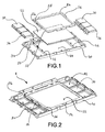
- FIG. 1 Fig. 3 shows an exploded perspective of a keyboard 1 according to an embodiment of the invention, seen from its rear side.
- the keyboard of the figure has six buttons 30 for actuating the controls 20.
- the buttons 30 are fixed and rotate about axes of rotation of the buttons 34, which are arranged on the frame 40 in each case in a group of three on each side of a frame window 44.
- the buttons 30 on the opposite side of the axis of rotation 34 have a button support projection 36 to accommodate on an edge of the frame 42 when the knob 30 from its installed position of FIG. 1 180 ° in its functional position of the FIG. 2 rotates.
- the button support projections have a groove that surrounds each pin and is very close to, but not touching, thereby allowing the free movement of the knob.
- a control display 22 is arranged to gain access to the information represented by the controls or function of the device.
- a locking piece in the form of a frame 54 is arranged, which is the entire perimeter of the window 44 covered.
- This locking piece in frame form has a locking piece edge 57, from which protrude three locking piece portions 56, which arrange in wing shape parallel to the window 44 in the direction of the buttons to lock three buttons 30.
- Each locking piece portion 56 has two holes to allow the pins of the locking elements 50 to enter, which, as soon as the locking piece is in frame form in its place on the display 22, protrude from the holes on the back of the locking piece 58.
- the locked buttons would work as in the Fig. 5 is shown, and the three unlocked according to FIG. 4 , Of course, the locked and unlocked buttons depend on the controls of the device; in the high quality could all be activated and the cheaper could all be locked except one.
- FIG. 2 is a perspective of the keyboard 1 according to the embodiment of the invention FIG. 1 shown, which is seen from the back.
- the buttons 30 are mounted on the frame axles 34 and rotated to their operative position.
- the display 22 is disposed on the rectangular frame window 44 enclosing it on its four sides and the locking piece in frame form 54 is on the display 22, forms a sandwich with the display and reliably locks it.
- the locking piece in frame form 54 has been connected to the frame 40 by the vibration welding method, and the pins of the locking member 50 have been simultaneously melted and joined to the locking piece 54, causing locking and locking of the buttons 30.
- the other three buttons remain unlocked and would function as in FIG. 4 is explained.
- FIG. 3 shows a perspective of a keyboard 1 according to the inventive embodiment of the preceding figures, which is seen from the front side. Both the buttons 30 and the frame 40 and the display 22 are balanced in an equal plane for aesthetic reasons.
- FIG. 4 shows a cross section of a keyboard 1 according to the inventive embodiment of the preceding figures with the unlocked button 30 in contact with a Control 20.
- the knob is engaged in its functional position on the axis of rotation of the knob 34 and on its opposite side it is supported on the frame edge 42 by the button support projection 36 from.
- the button support projection 36 has a recess which revolves around it and lies very close to the pin of the locking element 50, which is not deformed, goes beyond the back of the locking piece 58 and consequently allows the button free movement on its Knopfver einsweg 38.
- the locking element 50th is disabled and part of a frame piece 40, as well as the axis of rotation of the knob 34.
- the display of the control element 22 is supported and forms a sandwich with this and, by being locked, the locking piece 50 is arranged can be in the form of a frame or be part of it.
- the button tilts around the knob rotation axis 32 of the frame 40 and the connection to the control element 20 is realized by a changeover contact.
- the changeover contact system accommodates the potential deviations from existing tolerances between the button and the control, thereby ensuring their functionality.
- FIG. 5 shows a cross section of a keyboard 1 according to the inventive embodiment of the preceding figures with the already locked button 30, which has no control to activate.
- the button is locked in the axis of rotation of the knob 34 and on the opposite side it is supported on the frame edge 42 by the button support projection 36 from.
- the button support projection 36 has a recess which orbits it and is located very close to the pin of the locking element 50 which is deformed and protrudes beyond the back of the locking piece 58 covering the button support projection 36 as it passes through the opening in the area of the locking piece section 56. whereby it forms a sandwich with him against the frame edge 42 and as a result, the movement of the knob 30 is definitely blocked.
- the blocking element 50 is part of a part of the frame 40 and has been activated by means of vibration welding by means of the melting process.
- the button lock could be realized without locking piece 52 and without locking piece in frame 54. You could simply deform the pin of the locking element 50 on the button support projection 36 while blocking its movement.
- the recess of the button support projection 36 which surrounds the pin of the locking member 50 is very close to, surrounds this largely and when it is deformed by heat, it covers the back of the knob 32.
- the display 22 in this embodiment could be glued to the frame window or locking in any known manner or by melting a projection on the inside of the edge of the frame window is arranged to be connected to the same process of vibration melting, wherein the inside of the display is covered and the display is locked on the frame window in a solid and definitive position.
- buttons and changing the graphics that display their functions can be satisfied by simply locking buttons and changing the graphics that display their functions.
- the keypad which has more than one button on the frame, provides a one-piece bandage that provides the versatility required of such a wide range of different devices through a fitting method appropriate to each type of device. By attaching the keyboard only to a window present in the panel, the adjustment of the buttons to the controls is more reliable than when the display and buttons are each to be fastened separately.
Landscapes
- Engineering & Computer Science (AREA)
- Power Engineering (AREA)
- Push-Button Switches (AREA)
- Switch Cases, Indication, And Locking (AREA)
- Slide Switches (AREA)
- Input From Keyboards Or The Like (AREA)
Description
- Die vorliegende Erfindung betrifft eine Tastatur für ein Gerät, insbesondere ein Haushaltsgerät, mit mindestens einem Steuerelement, das in einer vorbestimmten Position des Steuerelements angeordnet ist. Die Tastatur weist mindestens einen Knopf, der zum Betätigen des Steuerelementes geeignet ist, einen Rahmen, in dem der Knopf verschiebbar in einer vorbestimmten Position des Knopfes vorsehbar ist, und ein Sperrelement auf. Außerdem betrifft die Erfindung ein Verfahren zum Einbau der Tastatur in Haushaltsgeräten.
- Fast alle Geräte, die nach dem Stand der Technik vorliegen, weisen Steuerelemente auf, die vom Nutzer zu betätigen sind, um deren funktionsseitige Wirkung zu erreichen.
- Bei der Fertigung der Schaltfelder der Geräte zum Betätigen der Steuerelemente werden auf der Vorderseite Knöpfe angeordnet. Die Knöpfe können u.a. in der Art von Druck-, Dreh-, Kipp- und Schiebeknöpfen sein.
- Insbesondere bei der Fertigung von Haushaltsgeräten ist es höchst üblich, dass dasselbe Gerät mit verschiedenen Funktionalitäten hergestellt wird. Der hochwertige Bereich weist eine höhere Anzahl an Funktionen und Steuerelementen, letztendlich Betätigungsknöpfen der Steuerelemente, auf als die Haushaltsgeräte des preisgünstigeren Bereiches.
- Demzufolge ist es notwendig, dass die Geräte des hochwertigen Bereiches mehr Knöpfe aufweisen, um die Steuerelemente zu steuern, als die des preisgünstigeren Bereiches, weshalb die Schalttafel oder das Schaltgehäuse mit Öffnungen versehen sein muss, um zu den Steuerknöpfen der Steuerelemente Zugriff zu haben. Diese Knöpfe sind Bestandteil einer Tastatur, die in dem Gerät eingebaut wird.
- Eine Form, die die Hersteller von Haushaltgeräten bei der Fertigung des Produktes zur Kostensenkung haben, ist die Herstellung eines einzigen Bedienfeldes für alle Qualitätsbereiche desselben Produktes mit allen erforderlichen Öffnungen und Zugriffen der Knöpfe der Tastaturen des Gerätes, die vorher bei der Herstellung der Vorderseite gefertigt werden.
- Diese gleiche Vorderseite des Bedienfeldes kann für ein Haushaltsgerät des niedrigsten Qualitätsbereiches mit einer geringeren Anzahl an Steuerelementen und folglich einer geringeren Anzahl an Funktionalitäten des Gerätes verwendet werden. Deshalb wird dieses Gerät des niedrigsten Qualitätsbereiches über weniger Knöpfe zur Betätigung der Steuerelemente verfügen. So verbleiben auf der Vorderseite des Bedienfeldes Öffnungen, die geschlossen werden müssen. Im Stand der Technik werden diese Öffnungen mit Abdeckungen bedeckt, die in die Öffnungen eingefügt werden. Die Befestigung kann durch Kleben, Klammern, Schrauben oder jede beliebige andere Form erfolgen.
- Aus der
DE 100 57 402 A1 , derDE 102 52 497 C1 , derUS 5,921,381 A und derEP 0 435 131 A sind Tastaturen bekannt, die für ein Haushaltsgerät konzipiert sind. Die Tastaturen weisen jeweils zumindest ein Steuerelement auf, dass in einer vorbestimmten Position angeordnet ist. Darüber hinaus umfasst die Tastatur einen Knopf, der zum Betätigen des Steuerelements ausgebildet ist. Darüber hinaus ist ein Rahmen vorgesehen, in dem der Knopf verschiebbar in einer vorbestimmten Position des Knopfs vorsehbar ist. Darüber hinaus sind jeweils Sperrelemente optional zum permanenten Sperren der Verschiebbarkeit des Knopfs in einem Zustand, in dem die Tastatur an einem Gerät angebracht ist und die Position des Steuerelements und die Position des Knopfs voneinander abweichen oder eine Funktion des Steuerelements mittels des Knopfs ausgeschlossen muss sein, bekannt. Optional kann ein Sperrelement vorgesehen sein, welches permanent zum Ermöglichen der Verschiebbarkeit des Knopfs in einem Zustand, in dem die Tastatur an dem Gerät angebracht ist und die Position des Steuerelements und die Position des Knopfs einander entsprechen und eine Funktion des Steuerelements mittels des Knopfs ermöglicht sein muss, ausgebildet ist. - Aufgabe der Erfindung ist demzufolge, eine Tastatur für ein Gerät mit größerer Wandlungsfähigkeit, Leichtigkeit der Montage in das Gerät und mit geringeren finanziellen Kosten als die Tastaturen des heutigen Standes der Technik sowie ein Verfahren zur Verfügung zu stellen.
- Gemäß einem ersten Aspekt der Erfindung wird diese Aufgabe durch eine Tastatur gemäß Anspruch 1.
- Dieselbe Tastatur kann in verschiedenen Geräten eingebaut werden, je nach der Notwendigkeit, ob ein Steuerelement des Gerätes aktiviert werden soll oder ein Steuerelement vorliegt, das durch den Knopf aktiviert wird, ohne ein anderes Element zum Verschließen der Öffnung, die durch den Knopf entstanden ist, zu verwenden. In dem Fall, in dem es nicht notwendig ist, dass der Knopf das Steuerelement des Gerätes aktiviert, blockiert das Sperrelement die Bewegung des Knopfes und somit übernimmt derselbe Knopf der Tastatur die Abdeckfunktion zum Verschließen der Öffnung des Knopfes oder für den Fall, dass das Steuerelement aktiviert werden soll, ist das Sperrelement nicht aktiviert und lässt der Bewegung des Knopfes zu dessen Verstellung freien Raum. Das Sperrelement kann in jeder beliebigen Art und Weise wirksam gemacht werden, beispielsweise, durch Verkleben, durch Klammern, durch Vibrationsschweißen, Gießschweißen, Heizelementschweißen, Ultraschallschweißen und/oder Festschrauben.
- Der Knopf ist ein Knopf, der aus einer Gruppe von Knöpfen gewählt wird, mit:
Druckknöpfen, Schiebeknöpfen und Drehknöpfen, weil eine Tastatur in einem Gerät einen oder mehrere dieser Knopfarten aufweisen kann, die gesperrt werden können oder müssen, da sie kein Steuerelement auslösen. - In einer Ausführung ist der Knopf im Rahmen drehbar befestigt, was diesem einen Stützpunkt hinsichtlich des Rahmens der Tastatur gibt und seine Betätigungsbewegung demzufolge eine Umdrehung bezüglich einer Drehachse des Rahmens ist.
- Der Rahmen weist einen Rahmenrand auf und der Knopf weist einen Knopfstützvorsprung auf, der auf dem Rahmenrand in einer Ruheposition des Knopfes ruhen kann, um den Knopf in dem Rahmen aufzunehmen. Dies stellt eine Ruheposition des Knopfes in dem Rahmen sicher und dass er keine unerwünschten Bewegungen bezüglich des Rahmens aufnimmt.
- In einer Ausführung weist der Rahmen ein Rahmenfenster auf, um ein Steuerelementendisplay zu arretieren. Für den Fall, dass das Steuerelement beispielsweise seinen Funktionszustand oder jede andere beliebige Information anzeigen soll, kann das mit Hilfe des Displays erfolgen, das in jeder beliebigen Art und Weise arretiert, angebracht oder befestigt ist, durch Ankleben, durch Vibrationsschweißen, Gießschweißen, Heizelementschweißen, Ultraschallschweißen und/oder Anschrauben an ein Rahmenfenster jeder beliebigen geometrischen Form, die aus einem Stück besteht oder mit dem Rahmen verbunden ist.
- In einer Ausführung ist das Sperrelement in dem Rahmen und/oder in dem Knopf angeordnet. In einer Weise, in der der eine mit dem anderen verbunden ist, oder wo das relative Verschieben zwischen beiden verhindert ist, damit sich der Knopf nicht bewegt, auch wenn er vom Nutzer gedrückt werden sollte.
- Das Sperrelement ist an der Rahmenrückseite und/oder der Knopfrückseite angeordnet, wobei es zum Innenbereich des Gerätes gerichtet ist und für den Nutzer unsichtbar ist.
- Das Sperrelement ist auf der einer Knopfdrehachse gegenüberliegenden Seite angeordnet, wobei die Rotation um die Achse blockiert ist.
- Das Sperrelement ist ein einstückiges schmelzbares Teil des Rahmens und/oder des Knopfes. Diese Ausführungsform erlaubt die Aufnahme des Sperrelementes in den Rahmen und/oder Knopf, wobei die Anzahl der Teile reduziert wird. Die Schmelzform des Sperrelementes kann, unter anderem, das Vibrationsschweißen, Gießschweißen, Heizelementschweißen, Ultraschallschweißen sein.
- Das Sperrelement erstreckt sich in einem geschmolzenen Zustand auf der Rückseite des Knopfes und auf der Rückseite des Rahmens. So wird die Bewegung durch das Schmelzen des einstückigen schmelzbaren Teiles des Rahmens und/oder des Knopfes mit einem leichten und schnellen Sperrsystem abgeblockt.
- Das Sperrelement weist ein Sperrstück auf. Es ist ein Stück, das nicht zum Rahmen und/oder Knopf gehört, das das Abblocken der relativen Bewegung des Knopfes realisieren kann.
- Das Sperrstück ist ein rahmenförmiges Sperrstück, das mit dem Rahmenfenster verbindbar ist. Die Verbindungsart zwischen beiden kann in jeder beliebigen Weise erfolgen, beispielsweise durch Kleben, mittels Klammern, durch Vibrationsschweißen, Gießschweißen, Heizelementschweißen, Ultraschallschweißen, Verschrauben, wobei die Öffnung beider vorzugsweise die gleiche Größe aufweist, damit die visuelle Erfassung der Informationen des Steuerelementes über das Display des Steuerelementes möglich ist.
- Das rahmenförmige Sperrstück weist zumindest einen Sperrstückabschnitt auf, der von einem Sperrstücksrand des rahmenförmigen Sperrstücks vorsteht, um auf einem Knopfstützvorsprung zu ruhen, wodurch eine Knopfverschiebungsstrecke gesperrt ist. Da das Sperrstück auf dem Rahmenfenster arretiert wird, verhindert der Sperrstückabschnitt direkt die Bewegung des Knopfes.
- Das Sperrelement erstreckt sich in einem geschmolzenen Zustand auf der Sperrstückrückseite. Es ist eine schnelle Art und Weise, durch das Schmelzen des Sperrelementes den Bewegungsweg des Knopfes abzublocken, wobei es mit der Rückseite des Knopfes verbunden wird.
- Der Knopf und/oder der Rahmen und/oder das Sperrelement sind aus Kunststoff gefertigt. Es ist besonders vorteilhaft für die Herstellung dieser Art von Tastaturen und zum Blockieren des Knopfes durch ein schmelzbares Sperrelement, weil das Schmelzen des Kunststoffes bei relativ niedrigen Temperaturen durchgeführt werden kann und dabei eine sehr zuverlässige Blockierung erreicht wird.
- Gemäß einem zweiten erfindungsgemäßen Aspekt wird diese Aufgabe durch ein Verfahren gemäß Anspruch 15.
- Die Beweglichkeit des Knopfes ist permanent blockiert, wenn das Sperrelement geschmolzen ist. Diese Methode ist sehr schnell und zuverlässig. Das Sperrelement kann durch Wärme geschmolzen werden, die durch ein Schweißverfahren durch Vibration oder Reibung entsteht.
- Die Beweglichkeit des Knopfes ist permanent blockiert, wenn das Sperrstück so an dem Rahmen befestigt ist, dass der Sperrabschnitt des Sperrstückes den Verstellungsweg des Knopfes blockiert, wobei das Sperrstück mit dem Rahmen oder mit dem Rahmenfenster, das gleichzeitig das Display des Steuerelementes arretiert, verbunden wird. Das Rahmenteil kann ebenfalls mit dem Rahmenfenster oder mit dem Rahmen durch Vibrationsschweißen verbunden werden. Wenn das Material, aus dem der Knopf, Rahmen und/oder Sperrstück gefertigt sind, Kunststoff ist, ist das Vibrationsschweißen ein sehr vorteilhaftes Verfahren.
- Die Figuren zeigen:
- Figur 1:
- zeigt eine Explosionsperspektive einer Tastatur gemäß einer Ausführung der Erfindung, die von ihrer Rückseite aus gesehen wird.
- Figur 2:
- zeigt eine Perspektive einer Tastatur gemäß einer Ausführung der Erfindung, die von ihrer Rückseite aus mit den auf den Achsen des Rahmens eingebauten Knöpfen gesehen wird.
- Figur 3:
- zeigt eine Perspektive einer Tastatur gemäß einer Ausführung der Erfindung, die von ihrer Vorderseite aus gesehen wird.
- Figur 4:
- zeigt einen Querschnitt einer Tastatur gemäß einer Ausführung der Erfindung mit dem nicht gesperrten Knopf in Kontakt mit einem Steuerelement.
- Figur 5:
- zeigt einen Querschnitt einer Tastatur gemäß einer Ausführung der Erfindung mit dem blockierten Knopf.
- In
Figur 1 wird eine Explosionsperspektive einer Tastatur 1 gemäß einer Ausführung der Erfindung gezeigt, die von ihrer Rückseite aus gesehen wird. Die Tastatur der Figur weist sechs Knöpfe 30 zum Betätigen der Steuerelemente 20 auf. Die Knöpfe 30 werden befestigt und drehen sich um Rotationsachsen der Knöpfe 34, die auf dem Rahmen 40 jeweils in einer Dreiergruppe auf jeder Seite eines Rahmenfensters 44 angeordnet sind. Die Knöpfe 30 auf der gegenüberliegenden Seite der Rotationsachse 34 weisen einen Knopfstützvorsprung 36 auf, um sich auf einem Rand des Rahmens 42 anzupassen, wenn sich der Knopf 30 aus seiner Einbauposition derFigur 1 um 180° in seine Funktionsposition derFigur 2 dreht. - Aus dem Rahmenrand 42 ragen einige Zapfen heraus, die die Sperrelemente 50 bilden. Die Knopfstützvorsprünge besitzen eine Auskehlung, die jeden Zapfen umgibt und dabei ganz in deren Nähe vorliegt, jedoch diese nicht berührt und dabei die freie Bewegung des Knopfes erlaubt.
- Auf dem Rahmenfenster 44 ist ein Steuerelementendisplay 22 angeordnet, um Zugang zur Information zu erhalten, die durch die Steuerelemente oder Funktion des Gerätes dargestellt wird. Auf dem Display 22 ist ein Sperrstück in Form eines Rahmens 54 angeordnet, das den gesamten Umkreis des Fensters 44 bedeckt. Dieses Sperrstück in Rahmenform weist einen Sperrstückrand 57 auf, von dem aus drei Sperrstückabschnitte 56 herausragen, die sich in Flügelform parallel zum Fenster 44 in Richtung der Knöpfe anordnen, um drei Knöpfe 30 zu sperren. Jeder Sperrstückabschnitt 56 hat zwei Löcher, um die Zapfen der Sperrelemente 50 eintreten zu lassen, die, sobald sich das Sperrstück in Rahmenform auf seinem Platz auf dem Display 22 befindet, aus den Löchern auf der Rückseite des Sperrstückes 58 herausragen. Die gesperrten Knöpfe würden so funktionieren, wie in der
Fig. 5 gezeigt wird, und die drei nicht gesperrten gemäßFigur 4 . Natürlich hängen die gesperrten und nicht gesperrten Knöpfe von den Steuerelementen des Gerätes ab; bei den hochwertigen könnten alle aktiviert werden und bei den preiswerteren könnten alle außer einem gesperrt sein. - In
Figur 2 wird eine Perspektive der Tastatur 1 gemäß der erfindungsgemäßen Ausführung derFigur 1 gezeigt, die von ihrer Rückseite aus gesehen wird. Die Knöpfe 30 sind auf den Rahmenachsen 34 montiert und in ihre Funktionsposition gedreht. Das Display 22 ist auf dem rechteckigen Rahmenfenster 44 angeordnet, das es an seinen vier Seiten einschließt und das Sperrstück in Rahmenform 54 befindet sich auf dem Display 22, bildet ein Sandwich mit dem Display und arretiert es zuverlässig. - Vom Rand des Sperrstückes 57 ragen die drei Sperrstückabschnitte 56 hervor und liegen auf den Knopfstützvorsprüngen 34 auf, bilden dabei ein Sandwich mit ihnen gegen den Rahmenrand 42. Die Zapfen des Sperrelementes 50 werden von den Ausnehmungen umringt, die jeden Zapfen ganz nah umringen und ragen aus den Öffnungen auf der Rückseite des Sperrstückes 58 heraus.
- Das Sperrstück in Rahmenform 54 ist durch das Vibrationsschweißverfahren mit dem Rahmen 40 verbunden worden und die Zapfen des Sperrelementes 50 wurden gleichzeitig geschmolzen und verbinden sich mit dem Sperrstück 54, wobei sie eine Arretierung und Sperrung der Knöpfe 30 bewirken. Die anderen drei Knöpfe verbleiben im nicht gesperrten Zustand und würden so funktionieren, wie in
Figur 4 erläutert ist. -
Figur 3 zeigt eine Perspektive einer Tastatur 1 gemäß der erfindungsgemäßen Ausführung der vorhergehenden Figuren, die von deren Vorderseite aus gesehen wird. Sowohl die Knöpfe 30 als auch der Rahmen 40 und das Display 22 sind aus ästhetischem Grund in einer gleichen Ebene abgeglichen. -
Figur 4 zeigt einen Querschnitt einer Tastatur 1 gemäß der erfindungsgemäßen Ausführung der vorhergehenden Figuren mit dem nicht gesperrten Knopf 30 in Kontakt mit einem Steuerelement 20. Der Knopf ist in seiner Funktionsstellung an der Rotationsachse des Knopfes 34 eingerastet und an seiner entgegengesetzten Seite stützt er sich am Rahmenrand 42 durch den Knopfstützvorsprung 36 ab. Der Knopfstützvorsprung 36 weist eine Ausnehmung auf, die diesen umläuft und ganz nah am Zapfen des Sperrelementes 50 liegt, das nicht verformt ist, geht über die Rückseite des Sperrstückes 58 hinaus und erlaubt infolgedessen dem Knopf die freie Bewegung auf seinem Knopfverstellungsweg 38. Das Sperrelement 50 ist deaktiviert und Bestandteil eines Rahmenstückes 40, genauso wie die Rotationsachse des Knopfes 34. Auf dem Innenteil des Rahmens 40 stützt sich das Display des Steuerelementes 22 ab und bildet ein Sandwich mit diesem und, indem es arretiert wird, wird das Sperrstück 50 angeordnet, das die Form eines Rahmens haben kann oder ein Teil von ihm selbst sein kann. In dieser Ausführung kippt der Knopf um die Knopfrotationsachse 32 des Rahmens 40 und die Verbindung mit dem Steuerelement 20 wird durch einen Umschaltkontakt realisiert. Durch das Umschaltkontaktsystem werden die möglichen Abweichungen durch bestehende Toleranzen zwischen dem Knopf und dem Steuerelement aufgenommen, wobei deren Funktionalität sichergestellt wird. -
Figur 5 zeigt einen Querschnitt einer Tastatur 1 gemäß der erfindungsgemäßen Ausführung der vorhergehenden Figuren mit dem bereits gesperrten Knopf 30, der kein Steuerelement zu aktivieren hat. Der Knopf ist in der Rotationsachse des Knopfes 34 eingerastet und auf der entgegengesetzten Seite stützt er sich am Rahmenrand 42 durch den Knopfstützvorsprung 36 ab. Der Knopfstützvorsprung 36 weist eine Ausnehmung auf, die ihn umkreist und ganz nah am Zapfen des Sperrelementes 50, das verformt ist, liegt und beim Durchqueren der Öffnung in dem Bereich des Sperrstückabschnittes 56 über die Rückseite des Sperrstückes 58 hinausragt, das den Knopfstützvorsprung 36 bedeckt, wobei es ein Sandwich mit ihm gegen den Rahmenrand 42 bildet und infolgedessen die Bewegung des Knopfes 30 definitiv blockiert. Das Sperrelement 50 ist Bestandteil eines Teils des Rahmens 40 und ist mit Hilfe des Schmelzverfahrens durch Vibrationsschweißen aktiviert worden. - In einer weiteren Ausführung, die nicht in den Figuren dargestellt wurde, könnte die Knopfsperrung ohne Sperrstück 52 und auch ohne Sperrstück in Rahmenform 54 realisiert werden. Man könnte einfach den Zapfen des Sperrelementes 50 auf dem Knopfstützvorsprung 36 verformen und dabei seine Bewegung blockieren. Die Ausnehmung des Knopfstützvorsprunges 36, die den Zapfen des Sperrelementes 50 umgibt, ist diesem sehr nahegelegen, umringt diesen größtenteils und wenn er durch Wärme verformt wird, bedeckt er die Rückseite des Knopfes 32. Das Display 22 in dieser Ausführung könnte mit dem Rahmenfenster durch Kleben oder Arretieren in jeder bekannten Weise oder auch durch Schmelzen eines Vorsprungs, der auf der Innenseite des Randes des Rahmenfensters angeordnet ist, mit dem selben Prozeß des Vibrationsschmelzens verbunden werden, wobei die Innenseite des Displays bedeckt wird und das Display auf dem Rahmenfenster in einer soliden und definitiven Position gesperrt wird.
- Es ist außerdem vorgesehen, dass von der Rückseite des Knopfes elastische, in den Figuren nicht dargestellte Arme, die mit diesem eine Einheit bilden, herausragen, damit, wenn der Knopf in Funktionsstellung ist und von dem Nutzer gegen das Steuerelement gedrückt wird, die Arme eine Federkraft ausüben, um den Knopf wieder in seine Ausgangsposition zu bringen.
- Mit einer einzigen Tastatur können alle Steuertafelvarianten aller Produktionsbereiche befriedigt werden, indem einfach nur Knöpfe gesperrt werden und die Graphik, die deren Funktionen anzeigt, geändert wird. Die Tastatur, die mehr als einen Knopf auf dem Rahmen aufweist, bietet einen einstückigen Verband, der durch ein für jeden Gerätetyp geeignetes Einbauverfahren einem so großen Bereich unterschiedlicher Geräte die geforderte Vielseitigkeit gibt. Dadurch, dass die Tastatur nur an einem Fenster, das in der Schalttafel vorliegt, zu befestigen ist, ist die Anpassung der Knöpfe an die Steuerelemente zuverlässiger, als wenn das Display und die Knöpfe jeder für sich zu befestigen sind.
- Es bezeichnen:
- 1
- Tastatur
- 20
- Steuerelement
- 22
- Display des Steuerelementes
- 30
- Knopf
- 32
- Rückseite des Knopfes
- 34
- Rotationsachse des Knopfes
- 36
- Knopfstützvorsprung
- 38
- Knopfverschiebungsstrecke
- 40
- Rahmen
- 42
- Rahmenrand
- 44
- Rahmenfenster
- 46
- Rückseite des Rahmens
- 50
- Sperrelement
- 52
- Sperrstück
- 54
- Sperrstück mit Rahmenform
- 56
- Sperrstückabschnitt
- 58
- Rückseite des Sperrstückes
Claims (16)
- Tastatur (1) für ein Gerät, insbesondere ein Haushaltsgerät, mit mindestens einem Steuerelement (20), das in einer vorbestimmten Position des Steuerelements (20) angeordnet ist, wobei die Tastatur (1) Folgendes aufweist:mindestens einen Knopf (30), der zum Betätigen des Steuerelements (20) geeignet ist;einen Rahmen (40), in dem der Knopf (30) verschiebbar in einer vorbestimmten Position des Knopfs (30) vorsehbar ist;und ein Sperrelement, das ein einstückiges schmelzbares Teil des Rahmens (40) und/oder des Knopfs (30) ist, wahlweise zum:dadurch gekennzeichnet, dassa) permanenten Sperren der Verschiebbarkeit des Knopfs (30) in einem Zustand, in dem
die Tastatur (1) in dem Gerät angebracht ist und die Position des Steuerelements (20) und die Position des Knopfs (30) voneinander abweichen oder eine Funktion des Steuerelements (20) mittels des Knopfs (30) ausgeschlossen sein muss; oderb) permanenten Ermöglichen der Verschiebbarkeit des Knopfs (30) in einem Zustand, in dem
die Tastatur (1) in dem Gerät angebracht ist und die Position des Steuerelements (20) und die Position des Knopfs (30) einander entsprechen und eine Funktion des Steuerelements (20) mittels des Knopfs (30) ermöglicht sein muss, wobei der Knopf (30) in dem Rahmen (40) fixierbar schwenkbar ist,
dass Sperrelement so ausgebildet ist, dass die Verschiebbarkeit des Knopfs (30) durch Schmelzen des Sperrelements (50) permanent gesperrt wird. - Tastatur nach Anspruch 1,
dadurch gekennzeichnet, dass
der Knopf (30) ein Knopf (30) aus einer Gruppe von Knöpfen ist, die Folgendes umfasst: Druckknöpfe, Schiebeknöpfe und Drehknöpfe. - Tastatur nach einem der vorhergehenden Ansprüche,
dadurch gekennzeichnet, dass
der Rahmen (40) einen Rahmenrand (42) aufweist und der Knopf (30) einen Knopfstützvorsprung (36) aufweist, der auf dem Rahmenrand (42) in einer Ruheposition des Knopfs (30) ruhen kann, um den Knopf (30) in dem Rahmen (40) aufzunehmen. - Tastatur nach einem der vorhergehenden Ansprüche,
dadurch gekennzeichnet, dass
der Rahmen (40) ein Rahmenfenster (44) zum Halten eines Steuerelementdisplays (22) aufweist. - Tastatur nach einem der vorhergehenden Ansprüche,
dadurch gekennzeichnet, dass
das Sperrelement (50) in dem Rahmen (40) und/oder in dem Knopf angeordnet ist. - Tastatur nach einem der vorhergehenden Ansprüche,
dadurch gekennzeichnet, dass
das Sperrelement (50) an der Knopfrückseite (32) und/oder der Rahmenrückseite (46) angeordnet ist. - Tastatur nach einem der vorherigen Ansprüche,
dadurch gekennzeichnet, dass
das Sperrelement (50) im gegenüberliegenden Teil einer Knopfdrehachse (34) angeordnet ist. - Tastatur nach einem der vorhergehenden Ansprüche,
dadurch gekennzeichnet, dass
sich das Sperrelement (50) in einem geschmolzenen Zustand über die Knopfrückseite (32) und die Rahmenrückseite (46) erstreckt. - Tastatur nach einem der vorhergehenden Ansprüche,
dadurch gekennzeichnet, dass
das Sperrelement (50) ein Sperrstück (52) aufweist. - Tastatur nach Anspruch 9,
dadurch gekennzeichnet, dass
das Sperrstück (52) ein rahmenförmiges Sperrstück (54) ist. - Tastatur nach Anspruch 10,
dadurch gekennzeichnet, dass
das rahmenförmige Sperrstück (54) mit dem Rahmenfenster (44) verbindbar ist. - Tastatur nach einem der Ansprüche 10 oder 11,
dadurch gekennzeichnet, dass
das rahmenförmige Sperrstück (54) mindestens einen Sperrstückabschnitt (56) aufweist, der von einem Sperrstückrand (57) des rahmenförmigen Sperrstücks (54) vorsteht, um auf einem Knopfstützvorsprung (36) zu ruhen, wodurch eine Knopfverschiebungsstrecke (38) gesperrt ist. - Tastatur nach einem der Ansprüche 9 bis 12,
dadurch gekennzeichnet, dass
sich das Sperrelement (50) in einem geschmolzenen Zustand über die Sperrstückrückseite (58) erstreckt. - Tastatur nach einem der vorhergehenden Ansprüche,
dadurch gekennzeichnet, dass
der Knopf (30) und/oder der Rahmen (40) und/oder das Sperrelement (50) aus Kunststoff hergestellt sind. - Verfahren zum Einrichten einer Tastatur (1) nach einem oder mehreren der Ansprüche 1 bis 14 in Geräten, insbesondere Haushaltsgeräten, die Steuerelemente bzw. verschiedene Positionen darin aufweisen, folgende Schritte aufweisend:a) beim Anbringen der Tastatur (1) in einem Gerät, bei dem die Position des Steuerelements (20) und die Position des Knopfs (30) voneinander abweichen oder eine Funktion des Steuerelements (20) mittels des Knopfs (30) ausgeschlossen sein muss: permanentes Sperren der Verschiebbarkeit des Knopfs (30) mittels des Sperrelements (50); undb) beim Anbringen der Tastatur (1) in dem Gerät, bei dem die Position des Steuerelements (20) und die Position des Knopfs (30) einander entsprechen und eine Funktion des Steuerelements (20) mittels des Knopfs (30) ermöglicht sein muss: permanentes Ermöglichen der Verschiebbarkeit des Knopfs (30) mittels des Sperrelements (50) in einem nicht gesperrten Zustand.
- Verfahren nach Anspruch 15 zum Einrichten einer Tastatur (1) nach Anspruch 12,
dadurch gekennzeichnet, dass
die Verschiebbarkeit des Knopfs (30) durch Schmelzen des Sperrelements (50) an den Rahmen (40) derart permanent gesperrt wird, dass der sperrabschnitt (56) des Sperrstücks (52) die Knopfverschiebungsstrecke (38) sperrt.
Applications Claiming Priority (1)
| Application Number | Priority Date | Filing Date | Title |
|---|---|---|---|
| ES200701016A ES2304891B1 (es) | 2007-04-04 | 2007-04-04 | Teclado para un aparato electrodomestico y metodo para instalarlo. |
Publications (3)
| Publication Number | Publication Date |
|---|---|
| EP1978534A2 EP1978534A2 (de) | 2008-10-08 |
| EP1978534A3 EP1978534A3 (de) | 2009-10-28 |
| EP1978534B1 true EP1978534B1 (de) | 2011-06-01 |
Family
ID=39494573
Family Applications (1)
| Application Number | Title | Priority Date | Filing Date |
|---|---|---|---|
| EP08102700A Not-in-force EP1978534B1 (de) | 2007-04-04 | 2008-03-18 | Tastatur für ein Haushaltgerät und Verfahren für deren Einbau |
Country Status (3)
| Country | Link |
|---|---|
| EP (1) | EP1978534B1 (de) |
| AT (1) | ATE511697T1 (de) |
| ES (1) | ES2304891B1 (de) |
Families Citing this family (1)
| Publication number | Priority date | Publication date | Assignee | Title |
|---|---|---|---|---|
| DE102008010217B3 (de) * | 2008-02-20 | 2009-09-10 | Preh Gmbh | Schalttafelanordnung mit Bedien- und Abdeckteil aus einem gemeinsamen Grundteil sowie ein Kraftfahrzeug und ein Haushaltsgerät damit |
Family Cites Families (9)
| Publication number | Priority date | Publication date | Assignee | Title |
|---|---|---|---|---|
| FR2656735B1 (fr) | 1989-12-28 | 1996-04-26 | Alcatel Business Systems | Clavier a touches captives. |
| US5921381A (en) | 1998-01-06 | 1999-07-13 | Watlow Electric Manufacturing Company | Locking button |
| SE521739C2 (sv) | 1999-11-19 | 2003-12-02 | Bt Ind Ab | Förfarande för anpassining av reglage vid maskiner samt reglage för utövande av förfarandet |
| WO2003001546A1 (en) * | 2001-06-22 | 2003-01-03 | Lg Electronics Inc. | Control panel assembly for home appliances and method for manufacturing the same |
| KR100593634B1 (ko) * | 2001-06-22 | 2006-06-30 | 주식회사 엘지이아이 | 가전기기의 콘트롤패널조립체 |
| DE10250497C1 (de) | 2002-10-29 | 2003-10-30 | Kieback & Peter Gmbh & Co Kg | Drucktasten-Schaltvorrichtung |
| DE10309516B3 (de) * | 2003-03-05 | 2004-11-25 | Electrolux Home Products Corporation N.V. | Tastenblock mit Federgeometrie |
| AU2004205205B2 (en) * | 2003-08-26 | 2009-06-04 | Lg Electronics Inc. | Control panel assembly and method for controlling thereof |
| KR20050081462A (ko) * | 2004-02-13 | 2005-08-19 | 엘지전자 주식회사 | 드럼 세탁기의 버튼 데코 설치구조 |
-
2007
- 2007-04-04 ES ES200701016A patent/ES2304891B1/es not_active Revoked
-
2008
- 2008-03-18 AT AT08102700T patent/ATE511697T1/de active
- 2008-03-18 EP EP08102700A patent/EP1978534B1/de not_active Not-in-force
Also Published As
| Publication number | Publication date |
|---|---|
| ATE511697T1 (de) | 2011-06-15 |
| ES2304891A1 (es) | 2008-10-16 |
| EP1978534A2 (de) | 2008-10-08 |
| EP1978534A3 (de) | 2009-10-28 |
| ES2304891B1 (es) | 2009-06-04 |
Similar Documents
| Publication | Publication Date | Title |
|---|---|---|
| DE3906473C2 (de) | Schließverriegelung | |
| EP1651833A1 (de) | Kraftfahrzeugt rverschluss | |
| DE102004011385B4 (de) | Vorrichtung zur Winkelverstellung einer um eine Drehachse drehbar vorgesehenen Komponente, insbesondere einer Armlehne in einem Fahrzeug | |
| DE69823317T2 (de) | Schlossgehäuse für Einbau in einer Tür oder ähnlichem | |
| DE19939090C2 (de) | Kraftfahrzeug-Drehschalteranordnung | |
| DE102004020655A1 (de) | Verriegelungseinheit für ein bewegliches Schließelement | |
| DE10324831B4 (de) | Bedienungsknopf zum Anschluss an einen Stellungsgeber mit selbstjustierender Drehführung | |
| WO2013056759A1 (de) | Mehrpolige schaltersicherungsanordnung für sammelschienensysteme | |
| DE102004007390A1 (de) | Verriegelungseinheit für ein bewegliches Schließelement | |
| DE102014102300B4 (de) | Verfahren zur Montage einer Türverriegelungs-/Entriegelungsbetätigungsvorrichtung zur Verriegelung/Entriegelung einer Fahrzeugtür | |
| EP3884554B1 (de) | Elektrisches installationsgerät | |
| DE1465705B1 (de) | Elektrischer Schnappschalter mit Drueckerhebel | |
| DE10392925T5 (de) | Zweipunkt-Verschlußsystem | |
| EP2318791B1 (de) | Abdeckleisten-baugruppe eines haushaltsgerätes | |
| EP0754827B1 (de) | Vorrichtung zur axial unverschieblichen, lösbaren Befestigung einer Handhabe an einem Lagerteil, insbesondere für Türdrücker, Fenstergriffe oder dgl. | |
| DE102004044672A1 (de) | Scharnieraufbau und Schutzvorrichtung mit einem Scharnieraufbau | |
| EP1978534A2 (de) | Tastatur für ein Haushaltgerät und Verfahren für deren Einbau | |
| DE4432343A1 (de) | Mit Mikroschaltern versehener Lenkstockschalter mit zwei Betriebsstellungen und einer Neutralstellung | |
| DE69907064T2 (de) | Lageeinstellungsvorrichtung eines Kfz-Scheinwerfers | |
| DE10307536B4 (de) | Blende mit rechteckigem Tastenblock und Verfahren zu dessen Herstellung | |
| EP0776020B1 (de) | Sicherheitsschaltvorrichtung | |
| EP1169593A1 (de) | Vorrichtung zum umkehrbaren verstellen eines ventilstössels | |
| DE2507910B2 (de) | Fehlbedienungssicherung für das Betätigungsgestänge eines Dreh-Kipp-Fensters | |
| EP0177811B1 (de) | Steuerschalter | |
| EP2138770A2 (de) | Haushaltsgerät, insbesondere Dunstabzugshaube, mit einem Scharnier und Scharnier für ein Haushaltsgerät |
Legal Events
| Date | Code | Title | Description |
|---|---|---|---|
| PUAI | Public reference made under article 153(3) epc to a published international application that has entered the european phase |
Free format text: ORIGINAL CODE: 0009012 |
|
| AK | Designated contracting states |
Kind code of ref document: A2 Designated state(s): AT BE BG CH CY CZ DE DK EE ES FI FR GB GR HR HU IE IS IT LI LT LU LV MC MT NL NO PL PT RO SE SI SK TR |
|
| AX | Request for extension of the european patent |
Extension state: AL BA MK RS |
|
| PUAL | Search report despatched |
Free format text: ORIGINAL CODE: 0009013 |
|
| AK | Designated contracting states |
Kind code of ref document: A3 Designated state(s): AT BE BG CH CY CZ DE DK EE ES FI FR GB GR HR HU IE IS IT LI LT LU LV MC MT NL NO PL PT RO SE SI SK TR |
|
| AX | Request for extension of the european patent |
Extension state: AL BA MK RS |
|
| 17P | Request for examination filed |
Effective date: 20100428 |
|
| 17Q | First examination report despatched |
Effective date: 20100601 |
|
| AKX | Designation fees paid |
Designated state(s): AT BE BG CH CY CZ DE DK EE ES FI FR GB GR HR HU IE IS IT LI LT LU LV MC MT NL NO PL PT RO SE SI SK TR |
|
| GRAP | Despatch of communication of intention to grant a patent |
Free format text: ORIGINAL CODE: EPIDOSNIGR1 |
|
| GRAS | Grant fee paid |
Free format text: ORIGINAL CODE: EPIDOSNIGR3 |
|
| GRAA | (expected) grant |
Free format text: ORIGINAL CODE: 0009210 |
|
| AK | Designated contracting states |
Kind code of ref document: B1 Designated state(s): AT BE BG CH CY CZ DE DK EE ES FI FR GB GR HR HU IE IS IT LI LT LU LV MC MT NL NO PL PT RO SE SI SK TR |
|
| REG | Reference to a national code |
Ref country code: GB Ref legal event code: FG4D Free format text: NOT ENGLISH |
|
| REG | Reference to a national code |
Ref country code: CH Ref legal event code: EP |
|
| REG | Reference to a national code |
Ref country code: IE Ref legal event code: FG4D Free format text: LANGUAGE OF EP DOCUMENT: GERMAN |
|
| REG | Reference to a national code |
Ref country code: DE Ref legal event code: R096 Ref document number: 502008003728 Country of ref document: DE Effective date: 20110714 |
|
| REG | Reference to a national code |
Ref country code: NL Ref legal event code: VDEP Effective date: 20110601 |
|
| PG25 | Lapsed in a contracting state [announced via postgrant information from national office to epo] |
Ref country code: HR Free format text: LAPSE BECAUSE OF FAILURE TO SUBMIT A TRANSLATION OF THE DESCRIPTION OR TO PAY THE FEE WITHIN THE PRESCRIBED TIME-LIMIT Effective date: 20110601 Ref country code: LT Free format text: LAPSE BECAUSE OF FAILURE TO SUBMIT A TRANSLATION OF THE DESCRIPTION OR TO PAY THE FEE WITHIN THE PRESCRIBED TIME-LIMIT Effective date: 20110601 Ref country code: NO Free format text: LAPSE BECAUSE OF FAILURE TO SUBMIT A TRANSLATION OF THE DESCRIPTION OR TO PAY THE FEE WITHIN THE PRESCRIBED TIME-LIMIT Effective date: 20110901 Ref country code: SE Free format text: LAPSE BECAUSE OF FAILURE TO SUBMIT A TRANSLATION OF THE DESCRIPTION OR TO PAY THE FEE WITHIN THE PRESCRIBED TIME-LIMIT Effective date: 20110601 |
|
| PG25 | Lapsed in a contracting state [announced via postgrant information from national office to epo] |
Ref country code: GR Free format text: LAPSE BECAUSE OF FAILURE TO SUBMIT A TRANSLATION OF THE DESCRIPTION OR TO PAY THE FEE WITHIN THE PRESCRIBED TIME-LIMIT Effective date: 20110902 Ref country code: LV Free format text: LAPSE BECAUSE OF FAILURE TO SUBMIT A TRANSLATION OF THE DESCRIPTION OR TO PAY THE FEE WITHIN THE PRESCRIBED TIME-LIMIT Effective date: 20110601 Ref country code: FI Free format text: LAPSE BECAUSE OF FAILURE TO SUBMIT A TRANSLATION OF THE DESCRIPTION OR TO PAY THE FEE WITHIN THE PRESCRIBED TIME-LIMIT Effective date: 20110601 Ref country code: CY Free format text: LAPSE BECAUSE OF FAILURE TO SUBMIT A TRANSLATION OF THE DESCRIPTION OR TO PAY THE FEE WITHIN THE PRESCRIBED TIME-LIMIT Effective date: 20110601 Ref country code: ES Free format text: LAPSE BECAUSE OF FAILURE TO SUBMIT A TRANSLATION OF THE DESCRIPTION OR TO PAY THE FEE WITHIN THE PRESCRIBED TIME-LIMIT Effective date: 20110912 Ref country code: SI Free format text: LAPSE BECAUSE OF FAILURE TO SUBMIT A TRANSLATION OF THE DESCRIPTION OR TO PAY THE FEE WITHIN THE PRESCRIBED TIME-LIMIT Effective date: 20110601 |
|
| REG | Reference to a national code |
Ref country code: IE Ref legal event code: FD4D |
|
| PG25 | Lapsed in a contracting state [announced via postgrant information from national office to epo] |
Ref country code: NL Free format text: LAPSE BECAUSE OF FAILURE TO SUBMIT A TRANSLATION OF THE DESCRIPTION OR TO PAY THE FEE WITHIN THE PRESCRIBED TIME-LIMIT Effective date: 20110601 |
|
| PG25 | Lapsed in a contracting state [announced via postgrant information from national office to epo] |
Ref country code: PT Free format text: LAPSE BECAUSE OF FAILURE TO SUBMIT A TRANSLATION OF THE DESCRIPTION OR TO PAY THE FEE WITHIN THE PRESCRIBED TIME-LIMIT Effective date: 20111003 Ref country code: IS Free format text: LAPSE BECAUSE OF FAILURE TO SUBMIT A TRANSLATION OF THE DESCRIPTION OR TO PAY THE FEE WITHIN THE PRESCRIBED TIME-LIMIT Effective date: 20111001 Ref country code: EE Free format text: LAPSE BECAUSE OF FAILURE TO SUBMIT A TRANSLATION OF THE DESCRIPTION OR TO PAY THE FEE WITHIN THE PRESCRIBED TIME-LIMIT Effective date: 20110601 Ref country code: IE Free format text: LAPSE BECAUSE OF FAILURE TO SUBMIT A TRANSLATION OF THE DESCRIPTION OR TO PAY THE FEE WITHIN THE PRESCRIBED TIME-LIMIT Effective date: 20110601 Ref country code: CZ Free format text: LAPSE BECAUSE OF FAILURE TO SUBMIT A TRANSLATION OF THE DESCRIPTION OR TO PAY THE FEE WITHIN THE PRESCRIBED TIME-LIMIT Effective date: 20110601 |
|
| PG25 | Lapsed in a contracting state [announced via postgrant information from national office to epo] |
Ref country code: RO Free format text: LAPSE BECAUSE OF FAILURE TO SUBMIT A TRANSLATION OF THE DESCRIPTION OR TO PAY THE FEE WITHIN THE PRESCRIBED TIME-LIMIT Effective date: 20110601 Ref country code: PL Free format text: LAPSE BECAUSE OF FAILURE TO SUBMIT A TRANSLATION OF THE DESCRIPTION OR TO PAY THE FEE WITHIN THE PRESCRIBED TIME-LIMIT Effective date: 20110601 Ref country code: SK Free format text: LAPSE BECAUSE OF FAILURE TO SUBMIT A TRANSLATION OF THE DESCRIPTION OR TO PAY THE FEE WITHIN THE PRESCRIBED TIME-LIMIT Effective date: 20110601 |
|
| PLBE | No opposition filed within time limit |
Free format text: ORIGINAL CODE: 0009261 |
|
| STAA | Information on the status of an ep patent application or granted ep patent |
Free format text: STATUS: NO OPPOSITION FILED WITHIN TIME LIMIT |
|
| 26N | No opposition filed |
Effective date: 20120302 |
|
| PG25 | Lapsed in a contracting state [announced via postgrant information from national office to epo] |
Ref country code: IT Free format text: LAPSE BECAUSE OF FAILURE TO SUBMIT A TRANSLATION OF THE DESCRIPTION OR TO PAY THE FEE WITHIN THE PRESCRIBED TIME-LIMIT Effective date: 20110601 |
|
| REG | Reference to a national code |
Ref country code: DE Ref legal event code: R097 Ref document number: 502008003728 Country of ref document: DE Effective date: 20120302 |
|
| PG25 | Lapsed in a contracting state [announced via postgrant information from national office to epo] |
Ref country code: DK Free format text: LAPSE BECAUSE OF FAILURE TO SUBMIT A TRANSLATION OF THE DESCRIPTION OR TO PAY THE FEE WITHIN THE PRESCRIBED TIME-LIMIT Effective date: 20110601 |
|
| BERE | Be: lapsed |
Owner name: BSH BOSCH UND SIEMENS HAUSGERATE G.M.B.H. Effective date: 20120331 |
|
| PG25 | Lapsed in a contracting state [announced via postgrant information from national office to epo] |
Ref country code: MC Free format text: LAPSE BECAUSE OF NON-PAYMENT OF DUE FEES Effective date: 20120331 |
|
| REG | Reference to a national code |
Ref country code: CH Ref legal event code: PL |
|
| GBPC | Gb: european patent ceased through non-payment of renewal fee |
Effective date: 20120318 |
|
| REG | Reference to a national code |
Ref country code: FR Ref legal event code: ST Effective date: 20121130 |
|
| PG25 | Lapsed in a contracting state [announced via postgrant information from national office to epo] |
Ref country code: LI Free format text: LAPSE BECAUSE OF NON-PAYMENT OF DUE FEES Effective date: 20120331 Ref country code: FR Free format text: LAPSE BECAUSE OF NON-PAYMENT OF DUE FEES Effective date: 20120402 Ref country code: CH Free format text: LAPSE BECAUSE OF NON-PAYMENT OF DUE FEES Effective date: 20120331 Ref country code: BE Free format text: LAPSE BECAUSE OF NON-PAYMENT OF DUE FEES Effective date: 20120331 Ref country code: GB Free format text: LAPSE BECAUSE OF NON-PAYMENT OF DUE FEES Effective date: 20120318 |
|
| PG25 | Lapsed in a contracting state [announced via postgrant information from national office to epo] |
Ref country code: BG Free format text: LAPSE BECAUSE OF FAILURE TO SUBMIT A TRANSLATION OF THE DESCRIPTION OR TO PAY THE FEE WITHIN THE PRESCRIBED TIME-LIMIT Effective date: 20110901 |
|
| PG25 | Lapsed in a contracting state [announced via postgrant information from national office to epo] |
Ref country code: MT Free format text: LAPSE BECAUSE OF FAILURE TO SUBMIT A TRANSLATION OF THE DESCRIPTION OR TO PAY THE FEE WITHIN THE PRESCRIBED TIME-LIMIT Effective date: 20110601 |
|
| PG25 | Lapsed in a contracting state [announced via postgrant information from national office to epo] |
Ref country code: TR Free format text: LAPSE BECAUSE OF FAILURE TO SUBMIT A TRANSLATION OF THE DESCRIPTION OR TO PAY THE FEE WITHIN THE PRESCRIBED TIME-LIMIT Effective date: 20110601 |
|
| PGFP | Annual fee paid to national office [announced via postgrant information from national office to epo] |
Ref country code: DE Payment date: 20140331 Year of fee payment: 7 |
|
| REG | Reference to a national code |
Ref country code: AT Ref legal event code: MM01 Ref document number: 511697 Country of ref document: AT Kind code of ref document: T Effective date: 20130318 |
|
| PG25 | Lapsed in a contracting state [announced via postgrant information from national office to epo] |
Ref country code: LU Free format text: LAPSE BECAUSE OF NON-PAYMENT OF DUE FEES Effective date: 20120318 |
|
| PG25 | Lapsed in a contracting state [announced via postgrant information from national office to epo] |
Ref country code: HU Free format text: LAPSE BECAUSE OF FAILURE TO SUBMIT A TRANSLATION OF THE DESCRIPTION OR TO PAY THE FEE WITHIN THE PRESCRIBED TIME-LIMIT Effective date: 20080318 |
|
| PG25 | Lapsed in a contracting state [announced via postgrant information from national office to epo] |
Ref country code: AT Free format text: LAPSE BECAUSE OF NON-PAYMENT OF DUE FEES Effective date: 20130318 |
|
| REG | Reference to a national code |
Ref country code: DE Ref legal event code: R119 Ref document number: 502008003728 Country of ref document: DE |
|
| PG25 | Lapsed in a contracting state [announced via postgrant information from national office to epo] |
Ref country code: DE Free format text: LAPSE BECAUSE OF NON-PAYMENT OF DUE FEES Effective date: 20151001 |