EP1978218A1 - Abgassystem für Grätschsitzfahrzeug - Google Patents
Abgassystem für Grätschsitzfahrzeug Download PDFInfo
- Publication number
- EP1978218A1 EP1978218A1 EP08251069A EP08251069A EP1978218A1 EP 1978218 A1 EP1978218 A1 EP 1978218A1 EP 08251069 A EP08251069 A EP 08251069A EP 08251069 A EP08251069 A EP 08251069A EP 1978218 A1 EP1978218 A1 EP 1978218A1
- Authority
- EP
- European Patent Office
- Prior art keywords
- exhaust
- muffler
- expansion chamber
- pipe
- exhaust valve
- Prior art date
- Legal status (The legal status is an assumption and is not a legal conclusion. Google has not performed a legal analysis and makes no representation as to the accuracy of the status listed.)
- Granted
Links
Images


Classifications
-
- F—MECHANICAL ENGINEERING; LIGHTING; HEATING; WEAPONS; BLASTING
- F01—MACHINES OR ENGINES IN GENERAL; ENGINE PLANTS IN GENERAL; STEAM ENGINES
- F01N—GAS-FLOW SILENCERS OR EXHAUST APPARATUS FOR MACHINES OR ENGINES IN GENERAL; GAS-FLOW SILENCERS OR EXHAUST APPARATUS FOR INTERNAL-COMBUSTION ENGINES
- F01N1/00—Silencing apparatus characterised by method of silencing
- F01N1/08—Silencing apparatus characterised by method of silencing by reducing exhaust energy by throttling or whirling
- F01N1/089—Silencing apparatus characterised by method of silencing by reducing exhaust energy by throttling or whirling using two or more expansion chambers in series
-
- F—MECHANICAL ENGINEERING; LIGHTING; HEATING; WEAPONS; BLASTING
- F01—MACHINES OR ENGINES IN GENERAL; ENGINE PLANTS IN GENERAL; STEAM ENGINES
- F01N—GAS-FLOW SILENCERS OR EXHAUST APPARATUS FOR MACHINES OR ENGINES IN GENERAL; GAS-FLOW SILENCERS OR EXHAUST APPARATUS FOR INTERNAL-COMBUSTION ENGINES
- F01N1/00—Silencing apparatus characterised by method of silencing
- F01N1/16—Silencing apparatus characterised by method of silencing by using movable parts
- F01N1/161—Silencing apparatus characterised by method of silencing by using movable parts for adjusting resonance or dead chambers or passages to resonance or dead chambers
- F01N1/163—Silencing apparatus characterised by method of silencing by using movable parts for adjusting resonance or dead chambers or passages to resonance or dead chambers by means of valves
-
- F—MECHANICAL ENGINEERING; LIGHTING; HEATING; WEAPONS; BLASTING
- F01—MACHINES OR ENGINES IN GENERAL; ENGINE PLANTS IN GENERAL; STEAM ENGINES
- F01N—GAS-FLOW SILENCERS OR EXHAUST APPARATUS FOR MACHINES OR ENGINES IN GENERAL; GAS-FLOW SILENCERS OR EXHAUST APPARATUS FOR INTERNAL-COMBUSTION ENGINES
- F01N1/00—Silencing apparatus characterised by method of silencing
- F01N1/16—Silencing apparatus characterised by method of silencing by using movable parts
- F01N1/166—Silencing apparatus characterised by method of silencing by using movable parts for changing the flow path through the silencer or for adjusting the dimensions of a chamber or a pipe
-
- F—MECHANICAL ENGINEERING; LIGHTING; HEATING; WEAPONS; BLASTING
- F01—MACHINES OR ENGINES IN GENERAL; ENGINE PLANTS IN GENERAL; STEAM ENGINES
- F01N—GAS-FLOW SILENCERS OR EXHAUST APPARATUS FOR MACHINES OR ENGINES IN GENERAL; GAS-FLOW SILENCERS OR EXHAUST APPARATUS FOR INTERNAL-COMBUSTION ENGINES
- F01N3/00—Exhaust or silencing apparatus having means for purifying, rendering innocuous, or otherwise treating exhaust
- F01N3/08—Exhaust or silencing apparatus having means for purifying, rendering innocuous, or otherwise treating exhaust for rendering innocuous
- F01N3/10—Exhaust or silencing apparatus having means for purifying, rendering innocuous, or otherwise treating exhaust for rendering innocuous by thermal or catalytic conversion of noxious components of exhaust
- F01N3/24—Exhaust or silencing apparatus having means for purifying, rendering innocuous, or otherwise treating exhaust for rendering innocuous by thermal or catalytic conversion of noxious components of exhaust characterised by constructional aspects of converting apparatus
- F01N3/28—Construction of catalytic reactors
- F01N3/2882—Catalytic reactors combined or associated with other devices, e.g. exhaust silencers or other exhaust purification devices
- F01N3/2885—Catalytic reactors combined or associated with other devices, e.g. exhaust silencers or other exhaust purification devices with exhaust silencers in a single housing
-
- F—MECHANICAL ENGINEERING; LIGHTING; HEATING; WEAPONS; BLASTING
- F01—MACHINES OR ENGINES IN GENERAL; ENGINE PLANTS IN GENERAL; STEAM ENGINES
- F01N—GAS-FLOW SILENCERS OR EXHAUST APPARATUS FOR MACHINES OR ENGINES IN GENERAL; GAS-FLOW SILENCERS OR EXHAUST APPARATUS FOR INTERNAL-COMBUSTION ENGINES
- F01N2230/00—Combination of silencers and other devices
- F01N2230/04—Catalytic converters
-
- F—MECHANICAL ENGINEERING; LIGHTING; HEATING; WEAPONS; BLASTING
- F01—MACHINES OR ENGINES IN GENERAL; ENGINE PLANTS IN GENERAL; STEAM ENGINES
- F01N—GAS-FLOW SILENCERS OR EXHAUST APPARATUS FOR MACHINES OR ENGINES IN GENERAL; GAS-FLOW SILENCERS OR EXHAUST APPARATUS FOR INTERNAL-COMBUSTION ENGINES
- F01N2490/00—Structure, disposition or shape of gas-chambers
- F01N2490/02—Two or more expansion chambers in series connected by means of tubes
- F01N2490/06—Two or more expansion chambers in series connected by means of tubes the gases flowing longitudinally from inlet to outlet in opposite directions
-
- F—MECHANICAL ENGINEERING; LIGHTING; HEATING; WEAPONS; BLASTING
- F01—MACHINES OR ENGINES IN GENERAL; ENGINE PLANTS IN GENERAL; STEAM ENGINES
- F01N—GAS-FLOW SILENCERS OR EXHAUST APPARATUS FOR MACHINES OR ENGINES IN GENERAL; GAS-FLOW SILENCERS OR EXHAUST APPARATUS FOR INTERNAL-COMBUSTION ENGINES
- F01N2590/00—Exhaust or silencing apparatus adapted to particular use, e.g. for military applications, airplanes, submarines
- F01N2590/04—Exhaust or silencing apparatus adapted to particular use, e.g. for military applications, airplanes, submarines for motorcycles
-
- Y—GENERAL TAGGING OF NEW TECHNOLOGICAL DEVELOPMENTS; GENERAL TAGGING OF CROSS-SECTIONAL TECHNOLOGIES SPANNING OVER SEVERAL SECTIONS OF THE IPC; TECHNICAL SUBJECTS COVERED BY FORMER USPC CROSS-REFERENCE ART COLLECTIONS [XRACs] AND DIGESTS
- Y02—TECHNOLOGIES OR APPLICATIONS FOR MITIGATION OR ADAPTATION AGAINST CLIMATE CHANGE
- Y02A—TECHNOLOGIES FOR ADAPTATION TO CLIMATE CHANGE
- Y02A50/00—TECHNOLOGIES FOR ADAPTATION TO CLIMATE CHANGE in human health protection, e.g. against extreme weather
- Y02A50/20—Air quality improvement or preservation, e.g. vehicle emission control or emission reduction by using catalytic converters
Definitions
- the present invention relates to an exhaust system for a saddle-ride type vehicle such as, for example, a motorcycle or a buggy.
- the present invention is concerned with the structure of a muffler which makes it possible to ensure a sufficient exhaust pipe length and a sufficient minimum road clearance.
- an exhaust system for a saddle-ride type vehicle wherein exhaust gas from an engine is discharged from a muffler through an exhaust pipe, the exhaust system comprising an exhaust valve disposed in an exhaust passage within the muffler to control the flow rate of the exhaust gas and a catalyst disposed within the exhaust pipe at a position near an open end as one end of the exhaust pipe, the one end of the exhaust pipe being open into the muffler.
- both exhaust valve and catalyst are disposed within the muffler, so in comparison with the case where both exhaust valve and catalyst are disposed separated within an exhaust system outside the muffler, it is not necessary to ensure any special place for mounting them and they can be mounted easily. Appearance is also improved. Moreover, since the whole can be made compact, it is possible to ensure a sufficient minimum road clearance. Further, since the catalyst is accommodated within the exhaust pipe at a position near the open end of the exhaust pipe, the exhaust pipe being accommodated within the muffler, the catalyst can be disposed by utilizing the exhaust pipe effectively and it is possible to ensure a sufficient length of the exhaust pipe.
- the exhaust valve can open and close the exhaust passage and it is urged in a normally closing direction and opens under the action of exhaust pressure.
- the structure is simple and less expensive in comparison with the electronically controlled type for example; besides, it is possible to make the system nearly maintenance-free.
- a separator is provided within the muffler to partition the interior of the muffler into an expansion chamber in which the open end of the exhaust pipe is disposed and an expansion chamber in which the exhaust valve is disposed, and an aperture is formed in the separator to provide communication between the adjacent expansion chambers, the aperture being opened and closed by the exhaust valve.
- the interior of the muffler is partitioned by a separator into an expansion chamber in which the open end of the exhaust pipe is located and an expansion chamber in which the exhaust valve is disposed, high-temperature exhaust gas just leaving the exhaust pipe can be prevented from direct contact with the exhaust valve and hence it is possible to improve both durability and reliability. Particularly, it is possible to increase the durability of the return spring.
- the separator functions as an exhaust gas flow uniforming plate when the aperture is closed by the exhaust valve. Hence, the exhaust gas leaving the open end of the exhaust pipe can be conducted smoothly toward an open end of a communication pipe for communication with the other expansion chamber.
- Fig. 1 schematically illustrates a motorcycle to which the present invention is applied.
- a multi-cylinder engine 3 is disposed between a front wheel 1 and a rear wheel 2 and exhaust pipes 4 (only one is shown in the figure) extending from exhaust ports of the cylinders are gathered as a manifold pipe 5 at a suitable position, for example, at a position under the engine 3, the manifold pipe 5 being connected to a muffler 6 which is generally triangular in side view.
- a bottom 7 of the muffler 6 is nearly parallel to the ground and ensures a predetermined minimum road clearance.
- An upper surface 8 of the muffler 6 extends backward and obliquely upward, with a tail pipe unit 9 being attached to a rear end of the muffler.
- Numeral 10 denotes a front fork, 11 a head pipe, 12 a main frame, 13 a pivot frame, 14 a pivot, 15 a rear frame, 16 a seat rail, and 17 a seat.
- Fig. 2 is a perspective view seeing through the interior of the muffler 6.
- the interior of a case 20 is partitioned into three chambers by a first separator 21 and a second separator 22, which chambers are assumed to be a first expansion chamber 23, a second expansion chamber 24 and a third expansion chamber 25 in order from the front side.
- the manifold pipe 5 gets into the second expansion chamber 24 sideways of a lower portion of the same chamber and extends upward substantially in parallel with the first separator 21 which is bent in the interior, with an open end 5a of the manifold pipe 5 being open upward.
- the second expansion chamber 24 communicates with the first expansion chamber 23 through a first connecting pipe 26 which is disposed in a lower portion of the first separator 21. Exhaust gas expanded in the second expansion chamber 24 is again throttled by the first connecting pipe 26 and enters the first expansion chamber 23, in which it expands again.
- the exhaust gas gets into a second connecting pipe 27 which extends through upper portions of the first and second separators 21, 22, and while being throttled thereby, it flows into the third expansion chamber 25, in which it undergoes the third expansion. Then, the exhaust gas passes through tail pipes 28 and is discharged into the atmosphere.
- the tail pipes two pipes different in diameter and length are used in combination.
- Numeral 29 denotes a supporting stay.
- a short-circuiting aperture 30 is formed in a lower portion of the second separator 22.
- an exhaust valve to be described later which is disposed on the third expansion chamber 25 side, becomes open, allowing the exhaust gas to flow directly from the second expansion chamber 24 into the third expansion chamber 25 to control the exhaust pressure.
- the short-circuiting aperture 30 is normally closed by a normally closed type exhaust valve 34 ( Fig. 4 ).
- Numeral 31 denotes a heat conducting plate disposed so as to cover the short-circuiting aperture 30 from above through a slight spacing, with punched holes being formed therein.
- a catalyst 32 is disposed within the manifold pipe 5 at a position near the open end 5a.
- the manifold pipe 5 may be a single exhaust pipe: By the generic term “exhaust pipe” as referred to herein it is meant to include a single exhaust pipe and a manifold pipe.
- the second connecting pipe 27 extends backward and obliquely upward, it conducts the exhaust gas flowing out from the open end 5a of the manifold pipe 5 to the upper portion side of the second separator 22. Further, the exhaust gas flows downward along the second separator 22 and reaches the short-circuiting aperture 30.
- the short-circuiting aperture 30 formed in the second separator 22 is closed with the exhaust valve 34 ( Fig. 4 )
- the second separator functions as it is as a flow uniforming plate for conducting the exhaust gas to the second expansion chamber 24-side open end of the first connecting pipe 26. If the short-circuiting aperture 30 is open, the exhaust gas flows directly into the third expansion chamber 25 through the short-circuiting aperture 30.
- a portion 7a of the bottom 7 of the case 20 which portion is contiguous to the lower portion of the second separator 22 is bent toward the open end of the first connecting pipe 26 and thus here again it is possible to obtain a flow uniforming effect.
- Fig. 3 is a side view seeing through the interior of the muffler 6.
- the two pipes are disposed so as to cover in a widened state the open end 5a (see Fig. 2 ) of the manifold pipe 5.
- the muffler 6 becomes thick in the expansion chamber 24 and thereby expands its capacity, in the interior of which is accommodated the open end 5a-side portion of the manifold pipe 5.
- the catalyst 32 which is cylindrical, is accommodated within the manifold pipe 5 at a position near the open end 5a. According to this arrangement, the manifold pipe 5 accommodated in the interior of the second expansion chamber 24 of a relatively large capacity can be made large in diameter and capacity, so that the catalyst 32 of a sufficient capacity can be accommodated within the manifold pipe 5.
- the open end 5a of the manifold pipe 5 is oriented in a slightly inclined state toward the first separator 21, so that the high-temperature exhaust gas just after leaving the opening end 5a does not directly advance toward the short-circuiting aperture 30, but strikes against the upper portion of the second separator 22 and an upper wall side of the muffler 6 and slows down, then forms a flow so as to descend along the second separator 22, whereby the exhaust gas can expand to a satisfactory extent throughout the whole of the second expansion chamber 24.
- the tail pipe unit 9 is constituted as an integral combination of the tail pipes 28, a decorative panel 9a which surrounds the tail pipes, and a partition wall through which the tail pipes 28 extend.
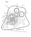
- Fig. 4 is a diagram showing the exhaust valve from behind.
- the exhaust valve 34 is in the shape of a disc which covers the short-circuiting aperture 30 and it is supported pivotably by a pivot shaft 35.
- a return spring 36 which is a coil spring. The return spring 36 urges the exhaust valve 34 in the closing direction.
- Both ends 37 of the return spring 36 are passed through mounting portions 38 provided on the outer periphery of the exhaust valve 34 and thereby urge the exhaust valve 34 for rotation.
- the strength of the return spring 36 is set so that the exhaust valve 34 rotates and opens under the action of a predetermined exhaust pressure. Therefore, when the exhaust pressure becomes high enough to overcome the spring load on the return spring 36, the exhaust valve 34 opens automatically, allowing the exhaust gas to flow out into the third expansion chamber 25 through the short-circuiting aperture 30 and thus making adjustment of the exhaust pressure.
- the exhaust valve 34 thus opens or closes automatically in accordance with the exhaust pressure, it is not necessary to use any special actuator for control and drive and it is possible to attain a simple and substantially maintenance-free structure. Besides, since the bottom 7 of the muffler 6 is inclined outwards and obliquely upward at a slight angle ⁇ , this also makes contribution to a large bank angle.
- the manifold pipe 5 Since the manifold pipe 5 is connected sideways to the second expansion chamber 24, the manifold pipe 5 can be connected to the second expansion chamber 24 which is thick and wide and it is possible to effect the connection of the manifold pipe 5 without exerting any influence on the minimum road clearance ( Fig. 1 ). If the manifold pipe 5 is connected to the first expansion chamber 23, it is required to thicken the first expansion chamber. In this case, if the first expansion chamber 23 is expanded downward, the minimum road clearance H becomes smaller and so does the bank angle.
- the muffler 6 is in a generally triangular shape of a large length in side view and its bottom 7 is made substantially horizontal, it is possible to make the minimum road clearance relatively large and thereby set a large bank angle. Also by forming the muffler in a generally triangular shape in side view and making the bottom 7 nearly parallel to the ground, it is possible to secure a minimum road clearance.
- the exhaust valve 34 is disposed in the third expansion chamber 25 partitioned by the second separator 22 from the second expansion chamber 24 into which the manifold pipe 5 opens. That is, the exhaust valve 34 is not disposed in the second expansion chamber 24 into which the exhaust gas flows out from the open end 5a while being raised in temperature through the catalyst 32. Consequently, it is possible to prevent the high-temperature exhaust gas from directly contacting the exhaust valve 34 and the return spring 36. In other words, it is possible to improve the durability of the exhaust valve 34 and that of the return spring 36. Moreover, since it is possible to diminish the influence of heat, the operation accuracy of the exhaust valve 34 is also improved. Additionally, it is not necessary to dispose the exhaust valve 34 and the return spring 36 at any special installation place in the exterior of the muffler 6, whereby the simplification and reduction in size of the entire system can be attained.
- the second connecting pipe 27 is disposed near the open end of the manifold pipe 5 to prevent the exhaust gas flowing out of the manifold pipe 5 from flowing directly toward the return spring 36, allowing the exhaust gas to flow toward the upper portion of the second separator 22 and the inner wall of the upper portion of the second expansion chamber 24. Further, a flow advancing downward along the second separator 22 is created and, when the exhaust valve 34 is closed, the second separator 22 functions as a flow uniforming plate for conducting the exhaust gas to the first connecting pipe 26 smoothly as a uniform flow.
- the second connecting pipe 27 can also be utilized as a flow uniforming member. Upon opening of the exhaust valve 34, the exhaust gas flows out immediately into the third expansion chamber 25 through the short-circuiting aperture 30, resulting in the exhaust pressure being reduced.
- the line connected to the muffler 6 from the engine side to introduce the exhaust gas into the muffler may be a manifold pipe or a single exhaust pipe.
- the return spring 36 is not limited to the coil spring. There may be used any of various types of springs. Further, the internal structure of the muffler 6 is arbitrary insofar the number of separators and that of expansion chambers are plural.
Landscapes
- Engineering & Computer Science (AREA)
- Chemical & Material Sciences (AREA)
- Combustion & Propulsion (AREA)
- Mechanical Engineering (AREA)
- General Engineering & Computer Science (AREA)
- Chemical Kinetics & Catalysis (AREA)
- Health & Medical Sciences (AREA)
- Toxicology (AREA)
- Exhaust Silencers (AREA)
- Exhaust Gas After Treatment (AREA)
Applications Claiming Priority (1)
| Application Number | Priority Date | Filing Date | Title |
|---|---|---|---|
| JP2007095621A JP4919864B2 (ja) | 2007-03-30 | 2007-03-30 | 鞍乗り型車両用排気装置 |
Publications (2)
| Publication Number | Publication Date |
|---|---|
| EP1978218A1 true EP1978218A1 (de) | 2008-10-08 |
| EP1978218B1 EP1978218B1 (de) | 2010-05-12 |
Family
ID=39587596
Family Applications (1)
| Application Number | Title | Priority Date | Filing Date |
|---|---|---|---|
| EP08251069A Not-in-force EP1978218B1 (de) | 2007-03-30 | 2008-03-26 | Abgassystem für Sitzfahrzeug |
Country Status (6)
| Country | Link |
|---|---|
| US (1) | US7905320B2 (de) |
| EP (1) | EP1978218B1 (de) |
| JP (1) | JP4919864B2 (de) |
| CA (1) | CA2625130C (de) |
| DE (1) | DE602008001190D1 (de) |
| MX (1) | MX2008003959A (de) |
Cited By (1)
| Publication number | Priority date | Publication date | Assignee | Title |
|---|---|---|---|---|
| WO2015172910A1 (de) * | 2014-05-16 | 2015-11-19 | Bayerische Motoren Werke Aktiengesellschaft | Abgasanlage mit variablen abgaswegen |
Families Citing this family (8)
| Publication number | Priority date | Publication date | Assignee | Title |
|---|---|---|---|---|
| WO2008022367A1 (en) | 2006-08-24 | 2008-02-28 | Global Valve Technology Limited | Centreline flow valve |
| US20090000862A1 (en) * | 2007-06-28 | 2009-01-01 | Buell Motorcycle Company | Motorcycle exhaust system |
| US20100270098A1 (en) * | 2009-04-24 | 2010-10-28 | Buell Motorcycle Company | Motorcycle with movable exhaust system |
| BRPI1015675B1 (pt) * | 2009-11-06 | 2023-02-14 | Bajaj Auto Limited | Sistema de exaustão para uma motocicleta |
| JP2011196242A (ja) | 2010-03-19 | 2011-10-06 | Kawasaki Heavy Ind Ltd | 自動二輪車の排気チャンバ |
| JP5484374B2 (ja) * | 2011-02-17 | 2014-05-07 | 本田技研工業株式会社 | 排気マフラー |
| DE102013111003B4 (de) * | 2012-10-31 | 2022-06-15 | Faurecia Emissions Control Technologies, Usa, Llc | Hybridventilbaugruppe, Verfahren zur Steuerung einer Hybridventilbaugruppe, sowie Ventilbaugruppe |
| JP2014234735A (ja) * | 2013-05-31 | 2014-12-15 | ヤマハ発動機株式会社 | 自動二輪車 |
Citations (6)
| Publication number | Priority date | Publication date | Assignee | Title |
|---|---|---|---|---|
| JPS55164711A (en) | 1979-06-11 | 1980-12-22 | Yamaha Motor Co Ltd | Exhaust gas silencing apparatus having reed valve |
| JPH0261312A (ja) * | 1988-08-24 | 1990-03-01 | Honda Motor Co Ltd | 2サイクルエンジンの排気装置 |
| DE10209577A1 (de) * | 2001-03-05 | 2002-09-19 | Honda Motor Co Ltd | Schalldämpfer mit Katalysator |
| JP2005105933A (ja) | 2003-09-30 | 2005-04-21 | Honda Motor Co Ltd | 自動二輪車の排気制御装置 |
| US20060000205A1 (en) | 2004-06-30 | 2006-01-05 | Harley-Davidson Motor Company Group, Inc. | Motorcycle dynamic exhaust system |
| JP2006207548A (ja) * | 2005-01-31 | 2006-08-10 | Honda Motor Co Ltd | 車両の排気装置 |
Family Cites Families (12)
| Publication number | Priority date | Publication date | Assignee | Title |
|---|---|---|---|---|
| WO1995013460A1 (en) * | 1993-11-09 | 1995-05-18 | Futaba Industrial Co., Ltd. | Muffler for an internal combustion engine |
| JP3214338B2 (ja) * | 1996-03-06 | 2001-10-02 | 日産自動車株式会社 | 自動車用排気消音装置 |
| JP3258554B2 (ja) * | 1996-03-12 | 2002-02-18 | 日産自動車株式会社 | 自動車用排気消音装置 |
| JP3546294B2 (ja) | 1998-04-28 | 2004-07-21 | トヨタ自動車株式会社 | 内燃機関の排気浄化装置 |
| DE69902085T2 (de) * | 1999-02-18 | 2003-01-30 | Hyundai Motor Co., Seoul/Soul | Semiaktiver Schalldämpfer für Brennkraftmaschine |
| JP3705969B2 (ja) * | 1999-10-21 | 2005-10-12 | 本田技研工業株式会社 | 消音器用バルブ装置 |
| JP3938481B2 (ja) * | 2001-08-22 | 2007-06-27 | 本田技研工業株式会社 | 自動二輪車の排気装置 |
| JP2004060631A (ja) * | 2002-07-31 | 2004-02-26 | Over Racing Projects:Kk | 自動二輪車用の触媒付マフラ構造 |
| US6644437B1 (en) * | 2002-08-02 | 2003-11-11 | General Motors Corporation | Vehicle exhaust with length-equalizing muffler |
| DE10311201A1 (de) * | 2003-03-14 | 2004-09-30 | Heinrich Gillet Gmbh | Schalldämpfer mit variabler Dämpfungscharakteristik |
| DE10316799A1 (de) * | 2003-04-11 | 2004-10-28 | Man Nutzfahrzeuge Ag | Kombinierte Abgasnachbehandlungs-/Schalldämpfungsvorrichtung im Abgasstrang einer Brennkraftmaschine |
| JP2007008442A (ja) * | 2005-03-11 | 2007-01-18 | Yamaha Motor Co Ltd | 自動二輪車の排気装置 |
-
2007
- 2007-03-30 JP JP2007095621A patent/JP4919864B2/ja not_active Expired - Fee Related
-
2008
- 2008-03-10 CA CA2625130A patent/CA2625130C/en not_active Expired - Fee Related
- 2008-03-25 MX MX2008003959A patent/MX2008003959A/es active IP Right Grant
- 2008-03-26 DE DE602008001190T patent/DE602008001190D1/de active Active
- 2008-03-26 US US12/055,570 patent/US7905320B2/en active Active
- 2008-03-26 EP EP08251069A patent/EP1978218B1/de not_active Not-in-force
Patent Citations (6)
| Publication number | Priority date | Publication date | Assignee | Title |
|---|---|---|---|---|
| JPS55164711A (en) | 1979-06-11 | 1980-12-22 | Yamaha Motor Co Ltd | Exhaust gas silencing apparatus having reed valve |
| JPH0261312A (ja) * | 1988-08-24 | 1990-03-01 | Honda Motor Co Ltd | 2サイクルエンジンの排気装置 |
| DE10209577A1 (de) * | 2001-03-05 | 2002-09-19 | Honda Motor Co Ltd | Schalldämpfer mit Katalysator |
| JP2005105933A (ja) | 2003-09-30 | 2005-04-21 | Honda Motor Co Ltd | 自動二輪車の排気制御装置 |
| US20060000205A1 (en) | 2004-06-30 | 2006-01-05 | Harley-Davidson Motor Company Group, Inc. | Motorcycle dynamic exhaust system |
| JP2006207548A (ja) * | 2005-01-31 | 2006-08-10 | Honda Motor Co Ltd | 車両の排気装置 |
Cited By (4)
| Publication number | Priority date | Publication date | Assignee | Title |
|---|---|---|---|---|
| WO2015172910A1 (de) * | 2014-05-16 | 2015-11-19 | Bayerische Motoren Werke Aktiengesellschaft | Abgasanlage mit variablen abgaswegen |
| CN105980678A (zh) * | 2014-05-16 | 2016-09-28 | 宝马股份公司 | 包括可变排气路径的排气系统 |
| US10221737B2 (en) | 2014-05-16 | 2019-03-05 | Bayerische Motoren Werke Aktiengesellschaft | Exhaust system having variable exhaust gas paths |
| CN105980678B (zh) * | 2014-05-16 | 2019-06-21 | 宝马股份公司 | 包括可变排气路径的排气系统 |
Also Published As
| Publication number | Publication date |
|---|---|
| US7905320B2 (en) | 2011-03-15 |
| DE602008001190D1 (de) | 2010-06-24 |
| EP1978218B1 (de) | 2010-05-12 |
| MX2008003959A (es) | 2009-02-27 |
| JP4919864B2 (ja) | 2012-04-18 |
| CA2625130A1 (en) | 2008-09-30 |
| JP2008255800A (ja) | 2008-10-23 |
| US20080236941A1 (en) | 2008-10-02 |
| CA2625130C (en) | 2010-12-07 |
Similar Documents
| Publication | Publication Date | Title |
|---|---|---|
| EP1978218B1 (de) | Abgassystem für Sitzfahrzeug | |
| JP4298835B2 (ja) | 自動二輪車の排気装置 | |
| JP2006307693A (ja) | 自動二輪車の排気装置 | |
| US7325651B2 (en) | Motorcycle exhaust system | |
| CN109989812B (zh) | 废气传感器的配置构造及排气控制系统 | |
| JP4545624B2 (ja) | ステアリングダンパ取り付け構造 | |
| US8302393B2 (en) | Exhaust system of an internal combustion engine | |
| US10907525B2 (en) | Vehicle exhaust device | |
| US8939255B2 (en) | Motorcycle | |
| KR101526401B1 (ko) | 터보차저용 웨이스트 게이트 어셈블리 | |
| JP5017194B2 (ja) | 車両の排気制御装置 | |
| US7874149B2 (en) | Exhaust apparatus for vehicle, and motorcycle having the same | |
| JP3859880B2 (ja) | 排気ガス再循環装置 | |
| JP2005188316A (ja) | 自動二輪車の排気装置 | |
| EP3951144B1 (de) | Abgasvorrichtung | |
| KR101517792B1 (ko) | Cda 엔진용 배기 소음장치 | |
| EP4495397A1 (de) | Installationsstruktur für eine luftsteuerungsvorrichtung | |
| KR102614150B1 (ko) | 차량의 가변형 배기밸브 및 차량의 가변형 배기밸브가 장착된 소음기 | |
| JP4345453B2 (ja) | 内燃機関の吸気装置 | |
| JP7059876B2 (ja) | 車両マフラの排出孔開閉装置 | |
| JP4589146B2 (ja) | 内燃機関の排気装置 | |
| JP2022030976A (ja) | バルブ内蔵型消音器 | |
| KR20060069641A (ko) | 자동차용 배기시스템의 소음방지 구조 | |
| JP2006046302A (ja) | 自動二輪車の排気装置 | |
| WO2022209880A1 (ja) | 内燃機関の吸気装置 |
Legal Events
| Date | Code | Title | Description |
|---|---|---|---|
| PUAI | Public reference made under article 153(3) epc to a published international application that has entered the european phase |
Free format text: ORIGINAL CODE: 0009012 |
|
| AK | Designated contracting states |
Kind code of ref document: A1 Designated state(s): AT BE BG CH CY CZ DE DK EE ES FI FR GB GR HR HU IE IS IT LI LT LU LV MC MT NL NO PL PT RO SE SI SK TR |
|
| AX | Request for extension of the european patent |
Extension state: AL BA MK RS |
|
| 17P | Request for examination filed |
Effective date: 20081126 |
|
| 17Q | First examination report despatched |
Effective date: 20090416 |
|
| AKX | Designation fees paid |
Designated state(s): DE FR GB IT |
|
| GRAP | Despatch of communication of intention to grant a patent |
Free format text: ORIGINAL CODE: EPIDOSNIGR1 |
|
| GRAS | Grant fee paid |
Free format text: ORIGINAL CODE: EPIDOSNIGR3 |
|
| GRAA | (expected) grant |
Free format text: ORIGINAL CODE: 0009210 |
|
| AK | Designated contracting states |
Kind code of ref document: B1 Designated state(s): DE FR GB IT |
|
| REG | Reference to a national code |
Ref country code: GB Ref legal event code: FG4D |
|
| REF | Corresponds to: |
Ref document number: 602008001190 Country of ref document: DE Date of ref document: 20100624 Kind code of ref document: P |
|
| PLBE | No opposition filed within time limit |
Free format text: ORIGINAL CODE: 0009261 |
|
| STAA | Information on the status of an ep patent application or granted ep patent |
Free format text: STATUS: NO OPPOSITION FILED WITHIN TIME LIMIT |
|
| 26N | No opposition filed |
Effective date: 20110215 |
|
| REG | Reference to a national code |
Ref country code: DE Ref legal event code: R097 Ref document number: 602008001190 Country of ref document: DE Effective date: 20110214 |
|
| REG | Reference to a national code |
Ref country code: DE Ref legal event code: R084 Ref document number: 602008001190 Country of ref document: DE |
|
| REG | Reference to a national code |
Ref country code: GB Ref legal event code: 746 Effective date: 20141114 |
|
| REG | Reference to a national code |
Ref country code: DE Ref legal event code: R084 Ref document number: 602008001190 Country of ref document: DE Effective date: 20141120 |
|
| REG | Reference to a national code |
Ref country code: FR Ref legal event code: PLFP Year of fee payment: 8 |
|
| PGFP | Annual fee paid to national office [announced via postgrant information from national office to epo] |
Ref country code: GB Payment date: 20150325 Year of fee payment: 8 Ref country code: FR Payment date: 20150309 Year of fee payment: 8 |
|
| PGFP | Annual fee paid to national office [announced via postgrant information from national office to epo] |
Ref country code: IT Payment date: 20160324 Year of fee payment: 9 |
|
| GBPC | Gb: european patent ceased through non-payment of renewal fee |
Effective date: 20160326 |
|
| REG | Reference to a national code |
Ref country code: FR Ref legal event code: ST Effective date: 20161130 |
|
| PG25 | Lapsed in a contracting state [announced via postgrant information from national office to epo] |
Ref country code: GB Free format text: LAPSE BECAUSE OF NON-PAYMENT OF DUE FEES Effective date: 20160326 Ref country code: FR Free format text: LAPSE BECAUSE OF NON-PAYMENT OF DUE FEES Effective date: 20160331 |
|
| PG25 | Lapsed in a contracting state [announced via postgrant information from national office to epo] |
Ref country code: IT Free format text: LAPSE BECAUSE OF NON-PAYMENT OF DUE FEES Effective date: 20170326 |
|
| PGFP | Annual fee paid to national office [announced via postgrant information from national office to epo] |
Ref country code: DE Payment date: 20190312 Year of fee payment: 12 |
|
| REG | Reference to a national code |
Ref country code: DE Ref legal event code: R119 Ref document number: 602008001190 Country of ref document: DE |
|
| PG25 | Lapsed in a contracting state [announced via postgrant information from national office to epo] |
Ref country code: DE Free format text: LAPSE BECAUSE OF NON-PAYMENT OF DUE FEES Effective date: 20201001 |