EP1973326A2 - Multifunktionsdrucker, Drucksystem und Standbilddruckprogramm - Google Patents
Multifunktionsdrucker, Drucksystem und Standbilddruckprogramm Download PDFInfo
- Publication number
- EP1973326A2 EP1973326A2 EP08005208A EP08005208A EP1973326A2 EP 1973326 A2 EP1973326 A2 EP 1973326A2 EP 08005208 A EP08005208 A EP 08005208A EP 08005208 A EP08005208 A EP 08005208A EP 1973326 A2 EP1973326 A2 EP 1973326A2
- Authority
- EP
- European Patent Office
- Prior art keywords
- image data
- correction
- data
- image
- printing
- Prior art date
- Legal status (The legal status is an assumption and is not a legal conclusion. Google has not performed a legal analysis and makes no representation as to the accuracy of the status listed.)
- Granted
Links
Images


Classifications
-
- H—ELECTRICITY
- H04—ELECTRIC COMMUNICATION TECHNIQUE
- H04N—PICTORIAL COMMUNICATION, e.g. TELEVISION
- H04N1/00—Scanning, transmission or reproduction of documents or the like, e.g. facsimile transmission; Details thereof
- H04N1/0035—User-machine interface; Control console
- H04N1/00352—Input means
- H04N1/00355—Mark-sheet input
- H04N1/00358—Type of the scanned marks
- H04N1/00366—Marks in boxes or the like, e.g. crosses or blacking out
-
- H—ELECTRICITY
- H04—ELECTRIC COMMUNICATION TECHNIQUE
- H04N—PICTORIAL COMMUNICATION, e.g. TELEVISION
- H04N1/00—Scanning, transmission or reproduction of documents or the like, e.g. facsimile transmission; Details thereof
- H04N1/0035—User-machine interface; Control console
- H04N1/00352—Input means
- H04N1/00355—Mark-sheet input
- H04N1/00368—Location of the scanned marks
- H04N1/00374—Location of the scanned marks on the same page as at least a part of the image
-
- H—ELECTRICITY
- H04—ELECTRIC COMMUNICATION TECHNIQUE
- H04N—PICTORIAL COMMUNICATION, e.g. TELEVISION
- H04N1/00—Scanning, transmission or reproduction of documents or the like, e.g. facsimile transmission; Details thereof
- H04N1/21—Intermediate information storage
- H04N1/2104—Intermediate information storage for one or a few pictures
- H04N1/2158—Intermediate information storage for one or a few pictures using a detachable storage unit
-
- H—ELECTRICITY
- H04—ELECTRIC COMMUNICATION TECHNIQUE
- H04N—PICTORIAL COMMUNICATION, e.g. TELEVISION
- H04N1/00—Scanning, transmission or reproduction of documents or the like, e.g. facsimile transmission; Details thereof
- H04N1/387—Composing, repositioning or otherwise geometrically modifying originals
-
- H—ELECTRICITY
- H04—ELECTRIC COMMUNICATION TECHNIQUE
- H04N—PICTORIAL COMMUNICATION, e.g. TELEVISION
- H04N2201/00—Indexing scheme relating to scanning, transmission or reproduction of documents or the like, and to details thereof
- H04N2201/0077—Types of the still picture apparatus
- H04N2201/0094—Multifunctional device, i.e. a device capable of all of reading, reproducing, copying, facsimile transception, file transception
Definitions
- the present invention relates to a multifunction printer, a printing system including the multifunction printer, and a still image printing program to be used for the multifunction printer.
- a technique has been hitherto known, in which a piece of still image data of a desired scene is extracted from a piece of movie image data composed of a plurality of pieces of still image data arranged in a chronological order, and an image of the still image data (still image) is printed on a printing medium.
- an image output device which is described in United States Patent No. 7,221, 470 (corresponding to Japanese Patent Application Laid-open No. 2003-264660 ), temporarily stores a plurality of pieces of still image data (frames) contained in movie image data.
- an instruction to print a still image is inputted by the remote control operation by a user
- a plurality of (for example, two) still images which are disposed in the vicinity of the time at which the printing instruction is inputted, are displayed on a screen.
- the data of the specified image is outputted to an image-forming device (for example, a color printer).
- An object of the present invention is to provide a multifunction printer which makes it possible to print a satisfactory still image by correcting any defective portion even when the defective portion is present in a part of a still image selected by a user.
- the correction position mark is the mark to indicate which area is to be corrected in the base image selected by the base image selection mark. Therefore, the correction position mark may be marked to any thumbnail image of the plurality of thumbnail images printed on the first printing medium. That is, the thumbnail image, to which the correction position mark is marked, may be different from or the same as the thumbnail image to which the base image selection mark is marked. It is not necessarily indispensable that the correction position mark is directly marked to the thumbnail image.
- the correction position mark may be marked at any position separated from the thumbnail image provided that the position at which the correction position mark is marked is successfully correlated with the area in which the thumbnail image is present.
- the base image data which corresponds to the thumbnail image marked with the base image selection mark
- the correction data-extracting section extracts the correction image data,for correcting the base image from the plurality of pieces of the still image data, the correction image data being instructed by the user or automatically set depending on the base image data.
- the data which is included in the correction image data and which corresponds to the correction position mark, is extracted as the correction data.
- the base image data and the correction data are combined or synthesized by the image-combining section, and thus the combined image data is generated.
- the image of the combined image data is outputted to the second printing medium.
- any defective portion portion unfavorite for the user
- the part can be replaced with the correction data which is extracted from the correction image data distinct from the base image data. It is possible to print the satisfactory image in which any defective portion is absent.
- the combined image in which a part of the base image is corrected, is automatically printed on the second printing medium such that the user views the list indication of the thumbnail images of the plurality of pieces of the still image data printed on the first printing medium and the user merely marks the base image selection mark and the correction position mark to the first printing medium to allow the scanner to read the printing medium. Therefore, it is unnecessary to perform any special operation which is not performed by the user during the ordinary image printing in order to print the combined image. Therefore, even in the case of the user who is weak in the equipment operation, it is possible to easily and conveniently print the combined still image of the desired scene in the moving image.
- the plurality of pieces of the still image data stored in the memory may be arranged in a chronological order.
- the correction data-extracting section may extract, as the correction image data, the still image data corresponding to the thumbnail image marked with the correction position mark.
- the correction data-extracting section judges that the instruction is made to correct the base image data by using the still image data corresponding to the correction position mark.
- the still image data which corresponds to the thumbnail image marked with the correction position mark, is extracted as the correction image data.
- the data which is included in the correction image data and which corresponds to the correction position mark, is cut out as the correction data. Therefore, the user can simultaneously perform the designation of the correction image data and the correction position by merely marking the correction position mark directly to the thumbnail image of the still image data to be used to correct the base image.
- the still image data when the base image selection mark and the correction position mark are marked to the same thumbnail image, the still image data, which is different from the still image data corresponding to the thumbnail image marked with the correction position mark, may be extracted as the correction image data by the correction data-extracting section.
- the correction data-extracting section judges that the correction position mark merely indicates the position of the area to be corrected in the base image.
- the still image data which is distinct from the still image data corresponding to the thumbnail image marked with the two types of the marks, is extracted as the correction image data.
- the data, which corresponds to the correction position mark of the correction image data is cut out as the correction data.
- a moving image identification mark which is provided to identify the movie image data, may be printed on the first printing medium together with the plurality of thumbnail images by the printing head, and the movie image data, from which the base image data and the correction image data are to be extracted, may be recognized from the moving image identification mark printed on the first printing medium by the image data-extracting section.
- the image data-extracting section recognizes the movie image data from which the base image data and the correction image data are to be extracted, from the moving image identification mark printed on the first printing medium. Therefore, it is unnecessary for the multifunction printer to inquire of the user from which movie image data the base image data and the correction image data are to be extracted.
- the plurality of pieces of the still image data may be classified into a plurality of groups, a group identification mark, which corresponds to each of the plurality of groups, may be printed by the printing head on one sheet of the first printing medium together with the thumbnail images of the still image data belonging to the group, and the group, from which the base image data and the correction image data are to be extracted, may be recognized by the image data-extracting section from the group identification mark printed on the first printing medium.
- the thumbnail images are shown in a list over a plurality of sheets of the first printing medium
- the plurality of pieces of the still image data are classified or divided into a plurality of groups in order to determine on which first printing medium the corresponding thumbnail image is printed.
- the thumbnail images of the still image data belonging to one group are printed on the same first printing medium, and the group identification mark corresponding to the group is printed on the same first printing medium.
- the image data-extracting section recognizes the group from which the base image data and the correction image data are to be extracted, from the group identification mark printed on the first printing medium. Therefore, it is unnecessary for the multifunction printer to inquire of the user from which group the base image data and the correction image data are to be extracted.
- any defective portion portion unfavorite for the user
- a part thereof can be replaced with the correction data extracted from the correction image data distinct from the base image data, in the same manner as in the first aspect. It is possible to print the satisfactory image.
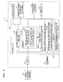
- the multifunction printer 1 of this embodiment comprises a printing head 2 which prints an image on the printing paper P (printing medium), a printing paper transport mechanism 3 which transports the printing paper P in a predetermined direction (frontward direction as shown in Fig. 1 ), a scanner 4 which reads the image printed on the printing paper P, and a controller 5 which controls various mechanisms of the multifunction printer 1 including, for example, the printing head 2, the printing paper transport mechanism 3, and the scanner 4 respectively.
- the multifunction printer 1 has a main printer body 6 having a substantially rectangular parallelepiped shape.
- the printing head 2 and the printing paper transport mechanism 3 are accommodated in the main printer body 6.
- Those usable as the printing head 2 include those based on the known system including, for example, the ink-jet system, the laser system, and the thermal transfer system for performing the printing on the printing paper P.
- the printing paper transport mechanism 3 is constructed such that the printing paper P is transported in the predetermined direction by the transport rollers driven and rotated by a motor.
- the scanner 4 is provided at an upper portion of the main printer body 6. As shown in Fig. 1 , the scanner 4 is provided with a placing stand (not shown) which is composed of a glass plate, a reading unit (not shown) which is arranged under the placing stand, and a cover 7 which covers the upper surface of the placing stand.
- the scanner 4 is constructed such that an image, which is printed on a manuscript, is read by the reading unit in a state in which the cover 7 is closed after the manuscript is placed on the upper surface of the placing stand.
- An inclined surface 6a is formed at a front upper portion of the main printer body 6.
- the inclined surface 6a is provided with an operating section 8 which is composed of a plurality of operation buttons to be operated by a user, and a display 9 which displays, for example, the error message and the operation state of the multifunction printer 1.
- a slot 10, to which a data-recording medium 11 such as a memory card is installed, is provided at a front right portion of the main printer body 6.
- the data including, for example, the movie image data and the image data recorded on the data-recording medium 11 is read in the slot 10, and the data is inputted into the controller 5.
- the data input into the multifunction printer 1 is not limited to such a system.
- the multifunction printer 1 may be connected to a digital video camera by a cable, and the data may be inputted into the multifunction printer 1 via the cable.
- the data may be inputted into the multifunction printer 1, for example, from a mobile phone equipped with the video photographing function via the wireless communication based on the use of, for example, the infrared light.
- the printing paper sheet P1 is read by the scanner 4 in a state in which a base image selection mark 31 for selecting a base image and a correction position mark 32 for instructing a correction area as a part of the base image are marked to the printing paper sheet P1 (first printing medium) printed with the thumbnail images 30 (see Fig. 6 ), the base image data corresponding to the base image selection mark 31 is combined with the correction data cut out or sliced out corresponding to the correction position mark 32 from the still image data (correction image data) which is distinct from the base image data.
- a combined image 38 image in which a part of the base image is corrected
- the controller 5 has a still image data-extracting section 22 which extracts the plurality of pieces of the still image data for the list indication or display (thumbnail indication) arranged in a chronological order, from the inputted movie image data.
- the storage section 21 of the controller 5 has a movie image data storage section 23 which temporarily stores the movie image data inputted from the data-recording medium 11, and a still image data storage section 24 which stores the plurality of still image data extracted by the still image data-extracting section 22 from the movie image data.
- the time interval T at which the still image data-extracting section 22 extracts the plurality of pieces of the still image data for the list indication from the movie image data 50, may be a preset fixed value or any value which is to be arbitrarily set by the user by the aid of the operating section 8.
- the still image data-extracting section 22 may set an appropriate value of the time interval T depending on the total period of time of the movie image data as the data extraction objective. For example, when the still image data are extracted from the movie image data in which the total period of time is long, the time interval T is increased. On the other hand, when the still image data are extracted from the movie image data in which the total period of time is short, the time interval T is decreased (made fine).
- the printing head 2 prints the movie image data ID 33 ("ABC": moving image identification mark) to identify the movie image data from which the still image data are extracted, at the upper-right position of the printing paper sheet P1. Further, the printing head 2 prints the time of the still image data corresponding to the thumbnail image 30 and a check box 34 at the position disposed just under each of the thumbnail images 30.
- ABC moving image identification mark
- the image data-extracting section 25 detects both of the marks 31, 32 (S14: Yes), the image data-extracting section 25 recognizes the movie image data from which the still image data is to be extracted, from the obtained movie image data ID 33.
- the image-combining section 28 combines the base image data extracted by the base image data-extracting section 26 with the correction data extracted by the correction data-extracting section 27 to generate the combined image data (S19). That is, the data, which is included in the base image data and which corresponds the area surrounded by the correction position mark 32, is replaced with the correction data cut out from the correction image data as the distinct still image data which is different from the base image data.
- the multifunction printer 1 of the first embodiment described above the following effect is obtained. That is, even when any defective portion (unfavorite portion for the user) is present in a part of the base image as the image which is intended to be printed by the user, the defective portion can be replaced with the correction data extracted from the correction image data distinct from the base image data. Therefore, it is possible to print the satisfactory image in which no defective portion is present.
- the correction data-extracting section 27 extracts, as the correction data from the correction image data, the data corresponding to the area marked with the correction position mark 32, of the thumbnail image 30. Therefore, the user can easily designate the correction position by directly marking the correction position mark 32 to the area on the thumbnail image 30 in which the base image is intended to be corrected. Further, the correction data-extracting section 27 cuts out, as the correction data, the data corresponding to the area surrounded by the correction position mark 32. Therefore, the user can instruct the correction area more finely by surrounding only the area intended to be corrected with the correction position mark 32. In other words, it is possible to avoid an inconvenience which would be otherwise caused such that the area of the base image, which is not required to be corrected, may be replaced with the correction image data in contravention of the intention of the user.
- the printing head 2 simultaneously prints the movie image data ID 33 (moving image identification mark) when the thumbnail images 30 are printed on the printing paper sheet P1. Therefore, when the printing paper sheet P1, which is marked with the base image selection mark 31 and the correction position mark 32, is read by the scanner 4, the image data-extracting section 25 can recognize the movie image data from which the base image data and the correction image data are to be printed, from the movie image data ID 33 printed on the printing paper sheet P1. In other words, it is unnecessary that the multifunction printer 1 should inquire of the user about from which movie image data the base image data and the correction image data are to be extracted.
- the printing head 2 simultaneously prints the plurality of check boxes 34 corresponding to the plurality of thumbnail images 30 respectively in order that the user easily marks the base image selection mark 31, when the plurality of thumbnail images 30 are printed on the printing paper sheet P1 (see Figs. 6 and 7 ).
- the printing head 2 it is possible to recognize the thumbnail image 30 selected by the mark 31 from the position at which the base image selection mark 31 is marked, irrelevant to the presence or absence of the check boxes 34. Therefore, it is not necessarily indispensable that the printing head 2 should print the check boxes 34 together with the plurality of thumbnail images 30.
- the user may directly write the mark 31 on any arbitrary thumbnail image 30, or the user may mark the mark 31 at any position disposed around the thumbnail images 30.
- the check boxes 34 are not printed, it is difficult to distinguish the base image selection mark 31 and the correction position mark 32 based on only the position information thereof. Accordingly, it is preferable that the two types of the marks 31, 32 are marked in different shapes so that the image data-extracting section 25 does not confuse the base image selection mark 31 and the correction position mark 32.
- the number of pieces of the still image data extracted from one piece of the movie image data is large depending on the total time of the movie image data and/or the time interval at which the still image data are extracted. All of the thumbnail images 30, which correspond to the pieces of the still image data, cannot be printed on one printing paper sheet P in some cases. In such a situation, the thumbnail images 30 of one piece of the movie image data are printed over a plurality of printing paper sheets P1.
- the still image data-extracting section 22 extracts, from the movie image data, the plurality of pieces of the still image data while dividing them into a plurality of groups.
- the printing control section 20 judges on which printing paper sheet P1 the thumbnail image 30 of a certain piece of the still image data is to be printed, from the group to which the still image data belongs.
- the printing head 2 is controlled on the basis thereof. In other words, the thumbnail images 30 of the plurality of pieces of the still image data belonging to a certain group are printed by the printing head 2 on one printing paper sheet P1.
- the printing head 2 preferably prints the thumbnail images 30 of the pieces of the still image data belonging to each of the groups on one printing paper sheet P1.
- the group identification mark 35 which corresponds to the group, is preferably printed on the same printing paper sheet P1.
- the group identification mark 35 of "3/6" shown in Fig. 8 indicates the third printing paper sheet P1 of the six printing paper sheets P1 in total on which the thumbnail images 30 are printed.
- the image data-extracting section 25 can recognize the positions at which the marks 31, 32 are marked, from the image data obtained by the scanner 4, and the image data-extracting section 25 can recognize the group from which the base image data and the correction image data are to be extracted, from the group identification mark 35. Therefore, it is unnecessary for the multifunction printer 1 to inquire of the user from which group the base image data and the correction image data are to be extracted.
- the multifunction printer 1 can recognize the group from which the base image data and the correction image data are to be extracted, by any other method, it is unnecessary for the printing head 2 to print the group identification mark 35 together with the thumbnail images 30 on the printing paper sheet P1.
- the following procedure is also available. That is, when the printing paper sheet P1, to which the marks 31, 32 are marked, is read by the scanner 4, then a message may be displayed on the display 9, and the user may input, from the operating section 8, which printing paper sheet P is read by the scanner 4.
- a plurality of correction position marks 32 may be marked by the user to the printing paper sheet P1 on which a plurality of thumbnail images 30 are printed.
- a base image selection mark-31 is marked to a thumbnail image 30 at the point of time of 14 hours 30 minutes 35 seconds of twelve thumbnail images 30 printed on the printing paper sheet P1.
- one correction position mark 32a is marked to a thumbna-il image 30 at the point of time 10 seconds before the thumbnail image 30 to which the base image selection mark 31 is marked.
- two correction position marks 32b, 32c are marked to a thumbnail image 30 at the point of time after 5 seconds.
- the base image-extracting section 26 extracts, as the base image data, the still image data at the point of time of 14 hours 30 minutes 35 seconds corresponding to the base image selection mark 31.
- the correction data-extracting section 27 extracts the still image data 10 seconds before the base image data and the still image data 5 seconds thereafter as the correction image data respectively. Further, the correction data-extracting section 27 extracts, as the correction data, the data corresponding to the mark 32a marked to the thumbnail image 30 which is 10 seconds before and the data corresponding to the marks 32b, 32c marked to the thumbnail image which is 5 seconds after respectively.
- the image-combining section 28 combines one piece of the base image data and three pieces of the correction data to generate the combined image data.
- the printing head 2 prints the image of the combined image data on the printing paper sheet P2.
- the image of the area A which is included in the combined image 38 printed on the printing paper sheet P2
- the image of the area B is the image of the correction data cut out from the correction image data (still image data at the point of time of 14 hours 30 minutes 25 seconds) earlier than the base image data by 10 seconds.
- the images of the areas C, D are the images of the two pieces of the correction data cut out from the correction image data (still image data at the point of time of 14 hours 30 minutes 40 seconds) later than the base image data by 5 seconds respectively.
- the data which corresponds to the area surrounded by the correction position mark 32 directly marked onto the thumbnail image 30, is cut out by the correction data-extracting section 27 as the correction data from the correction image data (see Fig. 7 ).
- the correction data-extracting section 27 As the correction data from the correction image data (see Fig. 7 ).
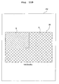
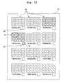
- the correction data-extracting section 27 may cut out, as the correction data, the entire data of the block areas 37 including the correction position mark 32 (upper-left four areas of the thumbnail image 30A marked with the correction position mark 32 in Fig. 11A ).
- the base image data and the correction data are combined with each other, and the combined image 38 is printed on the printing paper sheet P2 as shown in Fig.
- the area A of the combined image 38 is the image of the base image data
- the block area B which is disposed at the upper-left portion of the combined image 38 corresponding to the correction position mark 32, is the image of the correction data cut out from the correction image data.
- the correction position mark 32 is marked in the block area 37 to instruct one or a plurality of desired block area or areas 37. Therefore, any shape of the correction position mark 32 is available.
- it is not necessarily indispensable that the correction position mark 32 is formed to have the shape to surround the partial area of the thumbnail image 30 as in the first embodiment described above.
- the correction position mark 32 is directly marked onto the thumbnail image 30.
- the printing head 2 may print a plurality of check columns for the area selection correlated with the areas in the thumbnail images 30 around the respective thumbnail images 30.
- the correction area of the base image may be designated by marking the correction position marks 32 to the plurality of check columns for the area selection.
- the base image is selected by marking the base image selection mark 31 to a certain thumbnail image 30D by the user as shown in Fig. 11A .
- a combined image 38' as shown in Fig. 11C is printed on the printing paper sheet P2.
- the upper-left area A of the combined image 38' is the image of the correction data corresponding to the four upper-left block areas cut out from the thumbnail image 30A.
- the right area B of the combined image 38' is the image of the correction data corresponding to the eight right block areas cut out from the thumbnail image 30B.
- the lower-left area C is the image of the correction data corresponding to the four lower-left block areas cut out from the thumbnail image 30C.
- Step S17 may be executed when the image data-extracting section 25 detects the fact that the plurality of block areas 37 are marked without any excess and any deficiency so that one sheet of the combined image is established (S14: Yes).
- Step S15 may be executed.
- the thumbnail image 30, to which the base image selection mark 31 is marked by the user is different from the thumbnail images 30 to which the correction position mark 32 is marked.
- the base image selection mark 31 and the correction position mark 32 may be marked to the same thumbnail image 30.
- the correction data-extracting section 27 judges that the correction position mark 32 merely indicates the position of the area to be corrected in the base image. Therefore, the correction data-extracting section 27 extracts, as the correction image data, the still image data which is distinct from the still image data corresponding to the thumbnail image 30 marked with the base image selection mark 31 and the correction position mark 32. The data, which corresponds to the correction position mark 32 of the correction image data, is cut out as the correction data.
- the correction image data to be selected is not instructed by the correction position mark 32 unlike the first embodiment described above. Therefore, it is necessary to select the correction image data by any other technique. Accordingly, for example, the correction data-extracting section 27 may automatically adopt the still image data temporally positioned before and/or after the base image data, as the correction image data to be used for the correction of the base image. That is, as shown in Fig.
- the still image data which corresponds to the thumbnail image 30 marked with the correction image selection mark, may be adopted as the correction image data.
- Fig. 13 shows a block diagram schematically illustrating an electric configuration of a multifunction printer 41 according to the second embodiment.
- the multifunction printer 41 of the second embodiment is approximately the same as that of the first embodiment described above in relation to such a basic arrangement that the thumbnail images 30 of the still image data extracted from the movie image data are shown in a list on a printing paper sheet P1, and then the combined image 38 obtained by combining the base image and a part of the correction image selected by the user is printed on another printing paper sheet P2. Accordingly, in the following description, those constructed differently from those in the first embodiment will be principally explained. The components or parts, which are the same as or equivalent to those of the first embodiment described above, will be appropriately omitted from the explanation.
- the multifunction printer 41 of the second embodiment two or more pieces of the correction image data are extracted, and pieces of the correction data are cut out from the pieces of the correction image data. Further, the base image data is combined with the two or more of the correction data cut out from the correction image data respectively to generate two or more pieces of the to-be-printed data, and thumbnail images 60 of the to-be-printed data are printed on another printing paper sheet P3 (third printing medium) (see Fig. 17 ). In other words, the user can select one printing image which is believed as the best, from the plurality of combined images as the to-be-printeds.
- the printing paper sheet P3 is read by the scanner 4 in a state in which a predetermined printing selection mark 61 is marked by the user to an arbitrary thumbnail image 60 of the to-be-printed data (see Fig. 17 ).
- the controller 45 of the multifunction printer 41 of the second embodiment further comprises a printing image-identifying section 46.
- the to-be-printed data which corresponds to the printing selection mark 61 marked to the printing paper sheet P3, is identified or distinguished by the printing image-identifying section 46.
- the printing head 2 prints, on the printing paper sheet P2, the image 38 of the to-be-printed data identified by the printing image-identifying section 46.
- the still image data-extracting section 22 extracts a plurality of pieces of the still image data from the movie image data (S31), and the printing head 2 prints, on the printing paper sheet P1, a plurality of thumbnail images 30 corresponding to the plurality of the still image data respectively (S32).
- the printing head 2 also prints, on the printing paper sheet P1, a plurality of check boxes 34 corresponding to the plurality of thumbnail images 30 respectively.
- the base image selection mark 31 is marked by the user to the check box 34 corresponding to one thumbnail image 30.
- the correction position marks 32 are marked to other thumbnail images 30 distinct from the thumbnail image 30 to which the mark 31 is marked.
- the correction position marks 32 (32d to 32f) are marked to identical positions (upper-left positions) of the three thumbnail images 30 positioned temporally before and after the thumbnail image 30 to which the mark 31 is marked.
- the base image selection mark 31 and the correction position marks 32 are detected from the image data obtained by the scanner 4, by the image data-extracting section 25.
- the controller 45 allows the display 9 to show the error message to inform of the fact that the marks 31, 32 are not marked to the printing paper sheet P1 (S35).
- the base image-extracting section 26 extracts the base image data corresponding to the base image selection mark 31 (S36). Further, the correction data-extracting section 27 extracts the correction image data corresponding to the three correction position marks 32d to 32f respectively (S37). Further, the correction data-extracting section 27 cuts out, as the correction data from the three pieces of the extracted correction image data, the data corresponding to the positions (upper-left positions) to which the correction position marks 32 are marked (S38).
- the image-combining section 28 combines the base image data with the three pieces of the correction data cut out from the three pieces of the correction image data respectively to generate three pieces of to-be-printed data (S39). Simultaneously, the image-combining section 28 generates three pieces of thumbnail image data corresponding to the three pieces of the to-be-printed data respectively.
- the three pieces of the to-be-printed data and the thumbnail image data thereof generated in this process are stored in the still image data storage section 24.
- the printing head 2 prints, on the printing paper sheet P3, the thumbnail images 60 (to-be-printed thumbnail images) of the three pieces of the to-be-printed data generated by the image-combining section 28 (S40: third printing step).
- the printing head 2 prints, on the printing paper sheet P3, the times of the base image data and the correction image data as the sources of the three to-be-printed thumbnail images 60 and the check boxes 64 corresponding to the three to-be-printed thumbnail images 60 respectively together with the three to-be-printed thumbnail images 60.
- the predetermined printing selection mark 61 is marked by the user to the check box 64 of the thumbnail image 60 of the combined image intended to be finally printed.
- the printing selection mark 61 is detected from the image data obtained by the scanner 4, by the printing image-identifying section 46.
- the controller 45 allows the display 9 to show the error message to inform the user of the fact that the mark 61 is not marked to the printing paper sheet P1 (S43).
- the printing image-identifying section 46 detects the printing selection mark 61 (S42: Yes)
- the printing image-identifying section 46 identifies the to-be-printed thumbnail image 60 corresponding to the printing selection mark 61, of the three pieces of the to-be-printed data
- the printing image-identifying section 46 extracts the to-be-printed data corresponding to the thumbnail image 60 from the still image data storage section 24 (S44). Accordingly, as shown in Fig. 18 , the printing head 2 prints, on the printing paper sheet P2, the image 38 of the extracted to-be-printed data (combined image data).
- Fig. 18 the printing head 2 prints, on the printing paper sheet P2, the image 38 of the extracted to-be-printed data (combined image data).
- the area A of the combined image 38 printed on the printing paper sheet P2 is the image of the still image data (base image data) at the point of time of 14 hours 30 minutes 35 seconds
- the area B is the image of the correction data cut out from the still image data (correction image data) at the point of time of 14 hours 30 minutes 40 seconds.
- the multifunction printer 41 of the second embodiment described above the plurality of pieces of the correction image data are extracted, the plurality of pieces of the to-be-printed data are generated from the correction data cut out from the correction image data, and the thumbnail images 60 of the to-be-printed data are printed on the printing paper sheet P3. Therefore, the most favorite one is selected by the user from the thumbnail images 60 of the plurality of pieces of the to-be-printed data (combined image data) printed on the printing paper sheet P3, and thus the more satisfactory image can be printed on the printing paper sheet P2.
- the plurality of correction position marks 32 are marked by the user to the plurality of thumbnail images 30 printed on the printing paper sheet P1 (see Fig. 16 ), and thus the plurality of pieces of the still image data, which correspond to the plurality of thumbnail images 30 marked with the marks 32 respectively, are extracted as the correction image data.
- the correction image data may be extracted by any technique distinct therefrom.
- the base image selection mark 31 and the correction position mark 32 are marked to one thumbnail image 30 on the printing paper sheet P1.
- correction image selection marks 39a, 39b which are provided to instruct the correction image data, are marked to the check boxes 34 of the two thumbnail images 30 distinct from the thumbnail image 30 to which the base image selection mark 31 is marked respectively.
- the correction data-extracting section 27 judges that the correction position mark 32 merely indicates the position of the area to be corrected in the base image.
- the correction data-extracting section 27 recognizes the correction image data to be extracted, from the correction image selection marks 39a, 39b. For example, as shown in Fig. 19 , when the two correction image selection marks 39a, 39b are marked respectively to the two thumbnail images 30 which are separated temporally, a plurality of pieces of the still image data, which include the two pieces of the still image data corresponding to the two thumbnail images 30 marked with the marks 39a, 39b respectively and the still image data temporally disposed between the two pieces of the still image data, are extracted as the correction image data. Alternatively, only the two pieces of the still image data, which correspond to the two thumbnail images 30 marked with the two correction image selection marks 39a, 39b, may be extracted as the correction image data.
- correction image selection marks 39a, 39b are marked to the check boxes 34 as shown in Fig. 19 , it is preferable that the two types of the marks are marked in different shapes so that the correction image selection marks 39a, 39b and the base image selection mark 31 are not confused.
- the correction data-extracting section 27 may automatically adopt a plurality of still image data temporally positioned before and after the base image data, as the correction image data to be used for the correction of the base image.
- the controller of the multifunction printer performs all of the process for printing the still image.
- the printing system 100 of the third embodiment comprises a multifunction printer 71 which has the printing head 2 and the scanner 4, and a personal computer 72 (PC: control unit or controller) which controls the multifunction printer 71.
- PC control unit or controller
- the multifunction printer 71 has the printing head 2 and the scanner 4 as well as the printing paper transport mechanism 3, the operating section 8, the display 9, the controller 75 for controlling them, and other components.
- the multifunction printer 71 is principally constructed in the same manner as in the first embodiment described above. Therefore, any explanation thereof will be omitted.
- PC.72 is provided with, for example, CPU, ROM, RAM, and a mass storage device such as a hard disk.
- the mass storage device stores various types of data including, for example, movie image data and various application programs to be executed by CPU.
- the still image data-extracting section 82, the movie image data storage section 83, the still image data storage section 84, the image data-extracting section 85 (base image-extracting section 86 and correction data-extracting section 87), and the image-combining section 88 which are provided in the controller of the multifunction printer in the first embodiment described above, are provided in PC 72.
- the still image data-extracting section 82, the movie image data storage section 83, the still image data storage section 84, the image data-extracting section 85, and the image-combining section 88 are constructed, for example, by CPU, ROM, RAM, and the mass storage device of PC 72.
- the program which is stored in the mass storage device of PC 72, allows CPU of PC 72 to execute, for example, the base image-extracting step of extracting the base image data corresponding to the base image selection mark 31 (S16 in Fig. 3 ), the correction image-extracting step of extracting the correction image data corresponding to the correction position mark 32 (S17), the correction data-extracting step of cutting out the correction data from the correction image data (S18), and the image-combining step of combining the base image data and the correction data to generate the combined image data (S19).
- the function and the effect, which are to be consequently realized are approximately the same as those of the first embodiment described above, in spite of such a difference that parts of the processes, which include, for example, the extraction of the base image data and the correction data and the image combination, are performed on the side of PC 72.
- the times of the pieces of the still image data are also printed together therewith.
- those printed together with the thumbnail image are not limited thereto.
- the frame numbers are printed.
- the image may be selected by the user and the image may be recognized on the device side based on the frame number.
- the image-combining section 28, 88 may perform the correction so that the lightness and darkness of the coloration and/or the contrast may be equivalent in the vicinity of the boundary between the base image data and the correction data when the combined image data is generated.
- the present invention is applied to the procedure for printing the images of the plurality of pieces of the still image data extracted from the movie image data.
- the plurality of pieces of the still image data to be printed are not limited to those extracted from the movie image data, provided that they are arranged in a chronological order. Further, it is also unnecessary that the plurality of pieces of the still image data are arranged in a chronological order.
- the present invention is also applicable when a plurality of pieces of still image data, which are obtained by being photographed by a digital camera or the like, are stored in the storage means irrelevant to the times of being photographed.
- the still image data-extracting section 22 may extract pieces of still image data which are not arranged in a chronological order.
- the printing head 2 may print, on the printing paper sheet P1, a plurality of thumbnail images 30 corresponding to the still image data extracted by the still image data-extracting section.
- the user may mark the base image selection mark 31 and the correction position mark 32 to the printing paper sheet P1 on which the plurality of thumbnail images 30 are printed in the same manner as in the embodiment or the modified embodiments.
- the movie image data ID 33 and/or the group identification mark 35 are also printed together with the thumbnail images on the printing paper sheet P1.
- symbols or marks indicating the left, right, top and bottom of the printing paper sheet P1 may also be printed on a margin of the printing paper sheet P1.
- the movie image data ID 33 and/or the group identification mark 35 may be printed on the printing paper sheet P1 as marks which also indicate the left, right, top and bottom of the printing paper sheet P1.
Applications Claiming Priority (1)
| Application Number | Priority Date | Filing Date | Title |
|---|---|---|---|
| JP2007074061A JP2008236456A (ja) | 2007-03-22 | 2007-03-22 | プリンタ複合機、プリントシステム、及び、静止画像印刷プログラム |
Publications (3)
| Publication Number | Publication Date |
|---|---|
| EP1973326A2 true EP1973326A2 (de) | 2008-09-24 |
| EP1973326A3 EP1973326A3 (de) | 2010-01-20 |
| EP1973326B1 EP1973326B1 (de) | 2012-12-19 |
Family
ID=39468805
Family Applications (1)
| Application Number | Title | Priority Date | Filing Date |
|---|---|---|---|
| EP08005208A Expired - Fee Related EP1973326B1 (de) | 2007-03-22 | 2008-03-19 | Multifunktionsdrucker, Drucksystem und Standbilddruckprogramm |
Country Status (4)
| Country | Link |
|---|---|
| US (1) | US8289593B2 (de) |
| EP (1) | EP1973326B1 (de) |
| JP (1) | JP2008236456A (de) |
| CN (1) | CN101272436B (de) |
Families Citing this family (11)
| Publication number | Priority date | Publication date | Assignee | Title |
|---|---|---|---|---|
| JP5235550B2 (ja) * | 2008-07-31 | 2013-07-10 | キヤノン株式会社 | 画像処理装置、画像処理方法、プログラム及び記憶媒体 |
| JP5390828B2 (ja) * | 2008-10-17 | 2014-01-15 | キヤノン株式会社 | 画像処理装置、及び、画像処理方法 |
| JP2010147719A (ja) * | 2008-12-17 | 2010-07-01 | Canon Inc | 画像接合装置及びその制御方法 |
| JP5263630B2 (ja) * | 2010-11-24 | 2013-08-14 | カシオ計算機株式会社 | 画調変換装置およびプログラム |
| JP5959392B2 (ja) * | 2012-09-27 | 2016-08-02 | 京セラドキュメントソリューションズ株式会社 | 画像形成装置 |
| JP6068080B2 (ja) * | 2012-10-02 | 2017-01-25 | 日本電産サンキョー株式会社 | 画像結合装置、画像結合方法及びプログラム |
| JP2015103919A (ja) * | 2013-11-22 | 2015-06-04 | キヤノン株式会社 | 情報処理装置、システム、方法およびプログラム |
| JP2017033389A (ja) * | 2015-08-04 | 2017-02-09 | キヤノン株式会社 | 画像処理装置、画像読取方法、コンピュータプログラム、及び記憶媒体 |
| EP3510756B1 (de) * | 2016-09-12 | 2022-06-08 | Hewlett-Packard Development Company, L.P. | Scanner mit einem optischen sensor |
| US11079978B2 (en) | 2017-04-27 | 2021-08-03 | Hewlett-Packard Development Company, L.P. | Print in a user defined print area of a print media |
| CN110083315B (zh) * | 2019-03-20 | 2022-05-06 | 昆明理工大学 | 一种基于图像处理技术的打印错误更正方法 |
Citations (3)
| Publication number | Priority date | Publication date | Assignee | Title |
|---|---|---|---|---|
| JP2003264660A (ja) | 2001-12-12 | 2003-09-19 | Matsushita Electric Ind Co Ltd | 画像出力装置、画像形成装置および映像ハードコピー生成方法 |
| EP1696658A1 (de) | 2004-08-06 | 2006-08-30 | Seiko Epson Corporation | Bildverarbeitungssystem und bildverarbeitungsverfahren |
| US7221470B2 (en) | 2001-12-12 | 2007-05-22 | Matsushita Electric Industrial Co., Ltd. | Image output device, image forming device and method for generating video hard copy |
Family Cites Families (17)
| Publication number | Priority date | Publication date | Assignee | Title |
|---|---|---|---|---|
| US4627707A (en) * | 1984-06-16 | 1986-12-09 | Ricoh Company, Ltd. | Copier with image editing function |
| JPS63183467A (ja) * | 1987-01-27 | 1988-07-28 | Minolta Camera Co Ltd | 複写装置 |
| US5960109A (en) * | 1993-09-07 | 1999-09-28 | Xerox Corporation | Single pass marker enclosed area detection system and method for a photocopier |
| EP0686945B1 (de) * | 1994-05-26 | 2001-12-19 | Canon Kabushiki Kaisha | Bildverarbeitungsverfahren und -vorrichtung |
| US7263659B2 (en) * | 1998-09-09 | 2007-08-28 | Ricoh Company, Ltd. | Paper-based interface for multimedia information |
| US20010040685A1 (en) * | 1998-10-15 | 2001-11-15 | Hewlett-Packard Company | System and method for printing and scanning a user-completed digital still camera image proof sheet and order form |
| JP2000172826A (ja) * | 1998-12-02 | 2000-06-23 | Minolta Co Ltd | 画像合成装置 |
| EP1158766A1 (de) * | 2000-05-24 | 2001-11-28 | Hewlett-Packard Company, A Delaware Corporation | Verfahren und Vorrichtung zur Auswahl von Objekten |
| JP2002171398A (ja) * | 2000-12-04 | 2002-06-14 | Konica Corp | 画像処理方法及び電子カメラ |
| US6883892B2 (en) * | 2002-10-31 | 2005-04-26 | Hewlett-Packard Development Company, L.P. | Printing apparatus calibration |
| JP4404190B2 (ja) * | 2003-07-24 | 2010-01-27 | ソニー株式会社 | 電子機器、認証使用情報更新方法 |
| JP2005080076A (ja) * | 2003-09-02 | 2005-03-24 | Seiko Epson Corp | 印刷システム、方法及びプログラム |
| US20050128510A1 (en) * | 2003-12-16 | 2005-06-16 | Campbell Michael C. | Method for selecting images for action by an imaging apparatus |
| JP4412159B2 (ja) * | 2004-01-29 | 2010-02-10 | セイコーエプソン株式会社 | 画像処理装置、プリンタ及びプリンタの制御方法 |
| JP4416606B2 (ja) | 2004-09-07 | 2010-02-17 | キヤノン株式会社 | 表示制御装置及び表示制御方法、プログラム、記憶媒体 |
| US7596751B2 (en) * | 2005-04-22 | 2009-09-29 | Hewlett-Packard Development Company, L.P. | Contact sheet based image management |
| KR100679049B1 (ko) * | 2005-09-21 | 2007-02-05 | 삼성전자주식회사 | 인물 및 장소정보를 제공하는 썸네일에 의한 사진탐색 방법및 그 장치 |
-
2007
- 2007-03-22 JP JP2007074061A patent/JP2008236456A/ja active Pending
-
2008
- 2008-03-19 EP EP08005208A patent/EP1973326B1/de not_active Expired - Fee Related
- 2008-03-20 US US12/052,571 patent/US8289593B2/en not_active Expired - Fee Related
- 2008-03-24 CN CN2008100872512A patent/CN101272436B/zh not_active Expired - Fee Related
Patent Citations (3)
| Publication number | Priority date | Publication date | Assignee | Title |
|---|---|---|---|---|
| JP2003264660A (ja) | 2001-12-12 | 2003-09-19 | Matsushita Electric Ind Co Ltd | 画像出力装置、画像形成装置および映像ハードコピー生成方法 |
| US7221470B2 (en) | 2001-12-12 | 2007-05-22 | Matsushita Electric Industrial Co., Ltd. | Image output device, image forming device and method for generating video hard copy |
| EP1696658A1 (de) | 2004-08-06 | 2006-08-30 | Seiko Epson Corporation | Bildverarbeitungssystem und bildverarbeitungsverfahren |
Also Published As
| Publication number | Publication date |
|---|---|
| JP2008236456A (ja) | 2008-10-02 |
| CN101272436A (zh) | 2008-09-24 |
| US8289593B2 (en) | 2012-10-16 |
| EP1973326B1 (de) | 2012-12-19 |
| US20080231892A1 (en) | 2008-09-25 |
| CN101272436B (zh) | 2011-05-25 |
| EP1973326A3 (de) | 2010-01-20 |
Similar Documents
| Publication | Publication Date | Title |
|---|---|---|
| EP1973326B1 (de) | Multifunktionsdrucker, Drucksystem und Standbilddruckprogramm | |
| EP1973328B1 (de) | Multifunktionsdrucker, Drucksystem und Standbilddruckprogramm | |
| US7652709B2 (en) | Image forming device, image output device, image processing system, image retrieving method, image quality determining method and recording medium | |
| US8041149B2 (en) | Image processing apparatus, and control method and program of the same | |
| JP7380774B2 (ja) | 描画装置、描画方法及びプログラム | |
| US6226105B1 (en) | System for processing images by selecting appropriate document size | |
| JP2005174261A (ja) | 印刷装置、画像選択方法及び印刷方法 | |
| JP2018056894A (ja) | 画像編集プログラム及び画像編集装置 | |
| US20050206936A1 (en) | Improvements in and relating to printing | |
| US8279492B2 (en) | Image processing devices and computer program products for processing image data | |
| JP4432826B2 (ja) | プリントシステム及びプリント注文受付装置 | |
| JP4186116B2 (ja) | イメージ処理装置および方法 | |
| US20190174016A1 (en) | Display apparatus | |
| JPH11232006A (ja) | 出力装置、出力方法、及び、記憶媒体 | |
| JP2006142615A (ja) | ダイレクトプリンタ | |
| JP2006082397A (ja) | プリント装置、画像出力装置及び記録媒体の挿入口案内方法 | |
| JPH11239313A (ja) | 画像出力処理装置 | |
| JP4544226B2 (ja) | 画像編集装置 | |
| JP2004312487A (ja) | 画像記録装置、画像記録方法および記憶媒体 | |
| JP2000118103A (ja) | プリンタ | |
| JP2009272910A (ja) | 動画像印刷装置 | |
| JP2007226288A (ja) | 画像形成装置、データ記憶方法 | |
| JP2008015992A (ja) | 画像補正装置、印刷装置、画像補正方法、及び、プログラム | |
| JP2007221649A (ja) | 印刷システム |
Legal Events
| Date | Code | Title | Description |
|---|---|---|---|
| PUAI | Public reference made under article 153(3) epc to a published international application that has entered the european phase |
Free format text: ORIGINAL CODE: 0009012 |
|
| AK | Designated contracting states |
Kind code of ref document: A2 Designated state(s): AT BE BG CH CY CZ DE DK EE ES FI FR GB GR HR HU IE IS IT LI LT LU LV MC MT NL NO PL PT RO SE SI SK TR |
|
| AX | Request for extension of the european patent |
Extension state: AL BA MK RS |
|
| PUAL | Search report despatched |
Free format text: ORIGINAL CODE: 0009013 |
|
| AK | Designated contracting states |
Kind code of ref document: A3 Designated state(s): AT BE BG CH CY CZ DE DK EE ES FI FR GB GR HR HU IE IS IT LI LT LU LV MC MT NL NO PL PT RO SE SI SK TR |
|
| AX | Request for extension of the european patent |
Extension state: AL BA MK RS |
|
| RIC1 | Information provided on ipc code assigned before grant |
Ipc: H04N 1/21 20060101AFI20080704BHEP Ipc: H04N 1/00 20060101ALI20091215BHEP |
|
| 17P | Request for examination filed |
Effective date: 20100719 |
|
| AKX | Designation fees paid |
Designated state(s): DE FR GB |
|
| RIC1 | Information provided on ipc code assigned before grant |
Ipc: H04N 1/21 20060101AFI20120326BHEP Ipc: H04N 1/00 20060101ALI20120326BHEP Ipc: H04N 1/387 20060101ALI20120326BHEP |
|
| GRAP | Despatch of communication of intention to grant a patent |
Free format text: ORIGINAL CODE: EPIDOSNIGR1 |
|
| GRAS | Grant fee paid |
Free format text: ORIGINAL CODE: EPIDOSNIGR3 |
|
| GRAA | (expected) grant |
Free format text: ORIGINAL CODE: 0009210 |
|
| AK | Designated contracting states |
Kind code of ref document: B1 Designated state(s): DE FR GB |
|
| REG | Reference to a national code |
Ref country code: GB Ref legal event code: FG4D |
|
| REG | Reference to a national code |
Ref country code: DE Ref legal event code: R082 Ref document number: 602008020898 Country of ref document: DE Representative=s name: KUHNEN & WACKER PATENT- UND RECHTSANWALTSBUERO, DE |
|
| REG | Reference to a national code |
Ref country code: DE Ref legal event code: R096 Ref document number: 602008020898 Country of ref document: DE Effective date: 20130221 |
|
| PLBE | No opposition filed within time limit |
Free format text: ORIGINAL CODE: 0009261 |
|
| STAA | Information on the status of an ep patent application or granted ep patent |
Free format text: STATUS: NO OPPOSITION FILED WITHIN TIME LIMIT |
|
| 26N | No opposition filed |
Effective date: 20130920 |
|
| REG | Reference to a national code |
Ref country code: DE Ref legal event code: R097 Ref document number: 602008020898 Country of ref document: DE Effective date: 20130920 |
|
| REG | Reference to a national code |
Ref country code: FR Ref legal event code: PLFP Year of fee payment: 9 |
|
| REG | Reference to a national code |
Ref country code: FR Ref legal event code: PLFP Year of fee payment: 10 |
|
| REG | Reference to a national code |
Ref country code: FR Ref legal event code: PLFP Year of fee payment: 11 |
|
| PGFP | Annual fee paid to national office [announced via postgrant information from national office to epo] |
Ref country code: DE Payment date: 20190215 Year of fee payment: 12 Ref country code: GB Payment date: 20190227 Year of fee payment: 12 |
|
| PGFP | Annual fee paid to national office [announced via postgrant information from national office to epo] |
Ref country code: FR Payment date: 20190220 Year of fee payment: 12 |
|
| REG | Reference to a national code |
Ref country code: DE Ref legal event code: R119 Ref document number: 602008020898 Country of ref document: DE |
|
| PG25 | Lapsed in a contracting state [announced via postgrant information from national office to epo] |
Ref country code: DE Free format text: LAPSE BECAUSE OF NON-PAYMENT OF DUE FEES Effective date: 20201001 Ref country code: FR Free format text: LAPSE BECAUSE OF NON-PAYMENT OF DUE FEES Effective date: 20200331 |
|
| GBPC | Gb: european patent ceased through non-payment of renewal fee |
Effective date: 20200319 |
|
| PG25 | Lapsed in a contracting state [announced via postgrant information from national office to epo] |
Ref country code: GB Free format text: LAPSE BECAUSE OF NON-PAYMENT OF DUE FEES Effective date: 20200319 |