EP1970595B1 - Mechanismus zum Erzeugen von Dämpfungskraft - Google Patents
Mechanismus zum Erzeugen von Dämpfungskraft Download PDFInfo
- Publication number
- EP1970595B1 EP1970595B1 EP08004606.3A EP08004606A EP1970595B1 EP 1970595 B1 EP1970595 B1 EP 1970595B1 EP 08004606 A EP08004606 A EP 08004606A EP 1970595 B1 EP1970595 B1 EP 1970595B1
- Authority
- EP
- European Patent Office
- Prior art keywords
- valve body
- oil
- oil chamber
- chamber
- damping force
- Prior art date
- Legal status (The legal status is an assumption and is not a legal conclusion. Google has not performed a legal analysis and makes no representation as to the accuracy of the status listed.)
- Ceased
Links
Images


Classifications
-
- F—MECHANICAL ENGINEERING; LIGHTING; HEATING; WEAPONS; BLASTING
- F16—ENGINEERING ELEMENTS AND UNITS; GENERAL MEASURES FOR PRODUCING AND MAINTAINING EFFECTIVE FUNCTIONING OF MACHINES OR INSTALLATIONS; THERMAL INSULATION IN GENERAL
- F16F—SPRINGS; SHOCK-ABSORBERS; MEANS FOR DAMPING VIBRATION
- F16F9/00—Springs, vibration-dampers, shock-absorbers, or similarly-constructed movement-dampers using a fluid or the equivalent as damping medium
- F16F9/32—Details
- F16F9/44—Means on or in the damper for manual or non-automatic adjustment; such means combined with temperature correction
- F16F9/46—Means on or in the damper for manual or non-automatic adjustment; such means combined with temperature correction allowing control from a distance, i.e. location of means for control input being remote from site of valves, e.g. on damper external wall
Definitions
- This invention relates to a hydraulic pressure type damping force generating mechanism, and more specifically to a damping force generating mechanism applied to a steering damper of a motorcycle.
- JP2006-183864A published by the Japan Patent Office in 2006 discloses a steering damper interposed between handlebars and a vehicle body of a motorcycle to suppress unintended yaw or yaw oscillation of the front wheel while the motorcycle is running.
- This steering damper comprises a double-rod type damper cylinder and a damping force generating mechanism, which is formed in accordance with the preamble of claim 1, generating a damping force against the elongation/contraction of the damper cylinder, in a common housing.
- the damper cylinder comprises a cylinder barrel and a piston enclosed in the cylinder barrel.
- Two piston rods are fixed to either end face of the piston and project outwardly in an axial direction from the cylinder barrel.
- a first oil chamber and a second oil chamber having an identical cross-sectional area are formed by the piston in the cylinder barrel.
- the damping force generating mechanism comprises two valve bodies, i.e., a front valve body and a rear valve body, disposed coaxially in the housing.
- the two valve bodies are seated on two valve seats respectively.
- rear valve body is biased by a solenoid actuator towards a closed position.
- the rear valve body is in contact with the front valve body so as to bias the front valve body towards a closed position.
- Hydraulic pressure led from the first oil chamber in the damper cylinder is exerted on the front valve body towards an open position. Hydraulic pressure in the second oil chamber of the damper cylinder is led to a pressure chamber formed between the two valve bodies.
- both the front valve body and the rear valve body retreat from the respective valve seats, and the working oil flows out from the first oil chamber, passes along an outer circumferential surface of the front valve body, and flows into the second oil chamber via the pressure chamber between the two valve bodies.
- the hydraulic pressure in the second oil chamber rises in accordance with a displacement of the piston in a direction to compress the second oil chamber in the cylinder barrel
- the pressure in the pressure chamber between the two valve bodies rises such that only the rear valve body retreats from the corresponding valve seat.
- the working oil flows out from the pressure chamber between the two valve bodies, passes along an outer circumferential surface of the rear valve body, and flows into a pressure chamber formed on the rear side of the rear valve body.
- This pressure chamber is connected to the first oil chamber via a check valve, and hence the working oil in this pressure chamber flows into the first oil chamber via the check valve.
- each of the two valve bodies when lifted varies according to the lift amount.
- the damping force generating mechanism can generate a preferable damping force in relation to the lift amount of the valve bodies.
- This steering damper operates in a state where a cylinder barrel of the damper cylinder is engaged with one of a vehicle body and handlebars of a motorcycle while one of the piston rods is engaged with the other of the vehicle body and the handlebars of the motorcycle.
- the damping force generated according to the displacement of the piston in the cylinder barrel suppresses unintended yaw or yaw oscillation of the front wheel such that the riding comfort of the motorcycle is maintained.
- the steering damper Since the steering damper is disposed in a limited space between the front wheel and the vehicle body of a motorcycle, it is preferably made compact in size.
- a passage in which the check valve is installed is disposed perpendicular to the direction of displacement of the valve bodies in the damping force generating mechanism, and hence it is difficult to reduce the size of the housing that encloses the damping force generating mechanism.
- this invention provides a damping force generating mechanism according to claim 1.
- a damping force generating mechanism generates a damping force accompanying a flow of working oil between a first oil chamber and a second oil chamber, comprising a front valve body which allows working oil to flow from the first oil chamber to the second oil chamber under a predetermined resistance when lifted in an axial direction, a rear valve body which is disposed on the rear side of the front valve body coaxially therewith and allows working oil to flow from the second oil chamber to the first oil chamber under a predetermined resistance when lifted in the axial direction, a valve case which encloses the front valve body and the rear valve body, an oil passage formed through the valve case in parallel with a center axis of the front valve body and the rear valve body as a part of a flow path from the second oil chamber to the first oil chamber, and a check valve which allows working oil to flow from the oil passage into the first oil chamber while preventing working oil from flowing in a reverse direction.
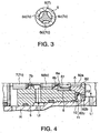
- a steering damper for a motorcycle comprises a damper cylinder D, a damping valve V which serves as a damping force generating mechanism, and an accumulator A.
- the damper cylinder D and the damping valve V are connected to each other by a passage L1 and a passage L2.
- the figure shows the construction of the damping valve V in detail, but shows the construction of the cylinder D, which is not a part of this invention, schematically.
- the damping valve V appears to be isolated from the cylinder D, the cylinder D and the damping valve V are enclosed in a common housing H together with the accumulator A.
- the cylinder D is a well known double-rod type cylinder.
- the cylinder D comprises a cylinder barrel 1, a piston 2 accommodated in the cylinder barrel 1 so as to be free to slide, and a pair of piston rods 3, 4 which are fixed to either end face of the piston 2 and project outwardly from the cylinder barrel 1 in an axial direction.
- the cylinder barrel 1 is connected to handlebars of a motorcycle while connecting one of the piston rods 3 or 4 to a vehicle body of the same.
- a first oil chamber R1 and a second oil chamber R2 are formed in the cylinder barrel 1 by the piston 2.
- a varied amount of oil in the first oil chamber R1 and a varied amount of oil in the second oil chamber R2 when the piston 2 displaces are inherently identical.
- damping valve V In addition to the damping valve V, it is possible to further provide another damping valve which allows working oil to flow between the oil chambers R1 and R2 in the piston 2.
- the damping valve V comprises a valve case 5 screwed into the housing H.
- a slide hole having a circular cross-section is formed in the center of the valve case 5.
- a front valve body 6 and a rear valve body 7 are fitted into the slide hole coaxially in series.
- the front valve body 6 is seated on a retractable valve seat 8 which is accommodated in the valve case 5.
- the retractable valve seat 8 is supported by a coil spring 81 in a direction to face the front valve body 6.
- the coil spring 81 is supported by a stopper 82 gripped between the valve case 5 and the housing H.
- the retractable valve seat 8 has a ring-shaped seat face, and the front valve body 6 comprises a conical tip 6b which penetrates a hole portion 8a surrounded by the seat face.
- the conical tip 6b has a function to define the flow cross-sectional area of the hole portion 8a when the front valve body 6 is lifted from the valve seat 8, or in other words retreats from the retractable valve seat 8.
- the valve body 7 is seated on a ring-shaped fixed valve seat 5b which is formed as a part of the housing 5.
- the valve body 7 comprises a conical tip 7b which penetrates a hole portion 5c surrounded by the fixed valve seat 5b.
- the conical tip 7b has a function to define a flow cross-sectional area of the hole portion 5c when the valve body 7 is lifted from the valve seat 5b, or in other words retreats from the fixed valve seat 5b.
- a push rod S1 is in contact with the rear face of the rear valve body 7.
- the push rod S1 projects from a solenoid actuator S fixed to the housing H.
- the solenoid actuator S biases the rear valve body 7 via the push rod S1 towards the fixed valve seat 5b, or in other words towards the closed position, according to an energizing current supplied from outside.
- the front valve body 6 comprises a rod portion 6d which projects axially rearward.
- the rear valve body 7 when biased by the push rod S1 towards the closed position causes the conical tip 7b to contact the rod portion 6d from behind.
- the retractable valve seat 8 is supported by the coil spring 81. This arrangement ensures that the front valve body 6 is supported by the rear valve body 7 via the conical tip rod 7b and the rod portion 6d becomes seated when the rear valve body 7 is seated on the valve seat 5b.
- the front valve body 6 and the rear valve body 7 thus constructed are supported in the valve case 5 so as to be free to displace in an axial direction.
- a pressure chamber C1 is formed in the housing H in front of the stopper 82.
- the pressure chamber C1 is permanently connected to the first oil chamber R1 of the cylinder D via a passage L1 formed in the housing H.
- the stopper 92 has a hollow part 82a and the hydraulic pressure of the pressure chamber C1 led through the hollow part 82a, is always exerted on the valve body 6.
- a pressure chamber C3 is formed in the housing H facing a rear end face of the rear valve body 7.
- the pressure chamber C3 is permanently connected to the accumulator A.
- a pressure chamber C2 is formed in the housing H so as to face the conical tip 7b of the rear valve body 7 and the rod portion 6b of the front valve body 6.
- the pressure chamber C2 is permanently connected to the second oil chamber R2 of the damper cylinder D via a passage L2 formed in the housing H.
- the front valve body 6 has three grooves 6c formed on the outer circumference thereof in the axial direction at equal angular intervals.
- the rear valve body 7 also has three grooves 7c formed on the outer circumference thereof in the axial direction at equal angular intervals.
- the grooves 6c function as a passage to cause working oil to flow from the pressure chamber C1 to the pressure chamber C2 when the front valve body 6 is lifted from the retractable valve seat 8.
- the grooves 7c function as a passage to cause working oil to flow from the pressure chamber C2 to the pressure chamber C3 when the rear valve body 7 is lifted from the fixed valve seat 5b
- a plurality of passages 5d are formed though the valve case 5 in parallel with a center axis of the valve bodies 6 and 7 as an oil passage to connect the pressure chamber C3 to the pressure chamber C1.
- An end of each passage 5d opens onto the pressure chamber C3.
- the other end of each passage 5d is closed by a check valve 10.
- the check valve 10 comprises a ring-shaped leaf valve 11.
- the leaf valve 11 is fitted onto the outer circumference of the stopper 82 coaxially with the valve bodies 6 and 7 and is maintained in a closed state by a return spring 12 constituted by a dish spring.
- the stopper 82 comprises a flange part 82c which is fitted into the housing H.
- the working oil that flows out from the check valve 10 is led to the pressure chamber C1 though through-holes 82b formed through the flange part 82c.
- the leaf valve 11 faces the opening of the other end of each passage 5d, and opens without resistance when working oil flows out from the passages 5d into the pressure chamber C1 while blocking working oil from flowing into the passages 5d from the pressure chamber C 1.
- the pressure in the pressure chamber C1 acts on the tip 6b of the front valve body 6 and causes the valve body 6 to retreat from the valve seat 8 against the biasing force of a solenoid actuator S, which is exerted on the front valve body 6 via the push rod S1 and the valve body 7.
- a solenoid actuator S which is exerted on the front valve body 6 via the push rod S1 and the valve body 7.
- working oil flows out from the first oil chamber R1 to the second oil chamber R2 via the passage L1, the pressure chamber C1, the hollow part 82a, the hole portion 8a, the grooves 6c on the outer circumferential surface of the front valve body 6, the pressure chamber C2, and the passage L2.
- the flow cross-sectional area of the hole portion 8a is defined by the gap between the tip 6b of the front valve body 6 and the valve seat 8. The flow resistance of this gap generates a damping force to damp the displacement of the piston 2.
- the pressure in the pressure chamber C2 acts on the tip 7b of the rear valve body 7 and causes the valve body 7 to retreat from the valve seat 5b against the biasing force of the solenoid actuator S, which is exerted on the rear valve body 7 via the push rod S1.
- working oil flows out from the second oil chamber R2 to the first oil chamber R1 via the passage L2, the pressure chamber C2, the hole portion 5c, the grooves 7c, the pressure chamber C3, the passages 5d, the check valve 10, the pressure chamber C1, and the passage L1.
- the flow cross-sectional area of the hole portion 5c is defined by the gap between the tip 7b of the rear valve body 7 and the valve seat 5b. The flow resistance of this gap generates a damping force to damp the displacement of the piston 2.
- the lift timing of the front valve body 6 and the rear valve body 7 depends on the voltage setting of the energizing current supplied to the solenoid actuator S.
- the damping force generated in a state where the front valve body 6 or the rear valve body 7 is lifted depends on the voltage of the energizing current supplied to the solenoid actuator S and the conical shape of the conical tip 6a, 7a. Variation in the working oil amount due to temperature variation is compensated by the accumulator A connected to the pressure chamber C3.
- the passages 5d are disposed in parallel with the sliding direction of the valve bodies 6 and 7, and the check valve 10, which limits the flow direction in the passages 5d is constituted by the leaf valve 11 which is disposed coaxially with the valve bodies 6 and 7.
- the steering damper according to this invention can make the housing H more compact than the housing of the prior art steering damper, in which the passage provided with the check valve is disposed perpendicular to the sliding direction of the valve bodies of the damping valve.
- the cylinder D and the damping valve V are accommodated in a common housing H. It is also possible, however, to accommodate the cylinder D and the damping valve V in separate housings. When this invention is applied to such a steering damper, the size of the damping valve housing can still be reduced.
- the damper cylinder D does not necessarily have to be a double rod type.
- the damper cylinder D may be constructed as a single rod type.
- the flow amount of working oil may be different depending on the sliding direction of the piston.
- the flow rate of the grooves 6c and 7c may be set differently, or the energizing current supplied to the solenoid actuator S may be varied depending on the sliding directions of the piston 2 in order to generate equal damping forces with respect to the two sliding directions of the piston 2.
- valve bodies 6 and 7 It is also possible to bias the valve bodies 6 and 7 towards the closed positions using a spring instead of the solenoid actuator S.
Landscapes
- Engineering & Computer Science (AREA)
- General Engineering & Computer Science (AREA)
- Mechanical Engineering (AREA)
- Axle Suspensions And Sidecars For Cycles (AREA)
- Fluid-Damping Devices (AREA)
- Check Valves (AREA)
- Magnetically Actuated Valves (AREA)
Claims (9)
- Mechanismus zum Erzeugen von Dämpfungskraft (V), der eine Dämpfungskraft in Verbindung mit einem Strömen von Arbeitsöl zwischen einer ersten Ölkammer (R1) und einer zweiten Ölkammer (R2) erzeugt, mit:einem vorderen Ventilkörper (6), der bei Anhebung in einer axialen Richtung ein Strömen von Arbeitsöl von der ersten Ölkammer (R1) zu der zweiten Ölkammer (R2) unter einem vorbestimmten Widerstand ermöglicht;einem hinteren Ventilkörper (7), der auf einer Rückseite des vorderen Ventilkörpers (6) und coaxial dazu angeordnet ist und bei Anhebung in der axialen Richtung ein Strömen von Arbeitsöl von der zweiten Ölkammer (R2) zu der ersten Ölkammer (R1) unter einem vorbestimmten Widerstand ermöglicht; undeinem Ventilgehäuse (5), das den vorderen Ventilkörper (6) und den hinteren Ventilkörper (7) umschließtgekennzeichnet durcheinen Öldurchlass (5d), der durch das Ventilgehäuse (5) hindurch parallel zu einer Mittelachse des vorderen Ventilkörpers (6) und des hinteren Ventilkörpers (7) als ein Teil eines Strömungspfads von der zweiten Ölkammer (R2) zu der ersten Ölkammer (R1) ausgebildet ist; undein Rückschlagventil (10), das ein Strömen von Arbeitsöl von dem Öldurchlass (5d) in die erste Ölkammer (R1) ermöglicht und ein Strömen von Arbeitöl in einer umgekehrten Richtung verhindert.
- Mechanismus zum Erzeugen von Dämpfungskraft (V) nach Anspruch 1, wobei der Öldurchlass (5d) mehrere Durchlässe aufweist, die in der Nähe des vorderen Ventilkörpers (6) und des hinteren Ventilkörpers (7) parallel zu der Mittelachse des vorderen Ventilkörpers (6) und des hinteren Ventilkörpers (7) angeordnet sind, und das Rückschlagventil (10) ein einziges Klappenventil (11) aufweist, das koaxial zu dem vorderen Ventilkörper (6) und dem hinteren Ventilkörper (7) so angeordnet ist, dass es mehrere Öffnungen der Durchlässe verschließt.
- Mechanismus zum Erzeugen von Dämpfungskraft (V) nach Anspruch 1 oder Anspruch 2, wobei der Mechanismus (V) ferner einen Elektromagnet-Aktuator (S) aufweist, der den hinteren Ventilkörper (7) in Richtung zu einer geschlossenen Position vorspannt, und wobei der hintere Ventilkörper (7) so angeordnet ist, dass er mit dem vorderen Ventilkörper (6) in Kontakt ist, um eine Vorspannkraft des Elektromagnet-Aktuators (S) zum Vorspannen des vorderen Ventilkörpers (6) in Richtung zu einer geschlossenen Position zu übertragen.
- Mechanismus zum Erzeugen von Dämpfungskraft (V) nach Anspruch 3, der ferner aufweist: einen zurückziehbaren Ventilssitz (8), der nachgiebig in einer Heberichtung des vorderen Ventilkörpers (6) gehalten wird, wobei der vordere Ventilkörper (6) ein Strömen von Arbeitsöl von der ersten Ölkammer (R1) zu der zweiten Ölkammer (R2) verhindert, wenn er auf dem zurückziehbaren Ventilsitz (8) aufliegt; und einen fixierten Ventilssitz (5b), auf welchem der hintere Ventilkörper (7) aufliegt, wobei der hintere Ventilkörper (7) ein Strömen von Arbeitsöl von der zweiten Ölkammer (R2) zu der ersten Ölkammer (R1) verhindert, wenn er auf dem fixierten Ventilsitz (5c) aufliegt.
- Mechanismus zum Erzeugen von Dämpfungskraft (V) nach Anspruch 4, der ferner ein Gehäuse (H) aufweist, das das Ventilgehäuse (5) umschließt, wobei eine Druckkammer (C1), die mit der ersten Ölkammer (R1) verbunden ist, an der Vorderseite des vorderen Ventilkörpers (6) ausgebildet ist, eine Druckkammer (C3), die mit dem Öldurchlass (5) verbunden ist, an der Hinterseite des hinteren Ventilkörpers (R2) ausgebildet ist, und eine Druckkammer (C2), die mit der zweiten Ölkammer (R2) verbunden ist, an der Vorderseite des hinteren Ventilkörpers (7) ausgebildet ist, wobei die Druckkammer (C1), die Druckkammer (C3) und die Druckkammer (C2) jeweils in dem Gehäuse (H) ausgebildet sind.
- Mechanismus zum Erzeugen von Dämpfungskraft (V) nach Anspruch 5, wobei der vordere Ventilkörper (6) eine Nut (6c) auf seiner äußeren Umfangsfläche so aufweist, dass bei Anhebung des vorderen Ventilkörpers (6) ein Strömen von Arbeitsöl von der Druckkammer (C1), die mit der ersten Ölkammer (R1) verbunden ist, zu der Druckkammer (C2), die mit der zweiten Ölkammer (R2) verbunden ist, hervorgerufen wird, und wobei der hintere Ventilkörper (7) eine Nut (7c) auf seiner äußeren Umfangsfläche so aufweist, dass bei Anhebung des hinteren Ventilkörpers (7) ein Strömen von Arbeitsöl von der ersten Druckkammer (C2), die mit der zweiten Ölkammer (R2) verbunden ist, zu der Druckkammer (C3), die mit dem Oldurchlass (5d) verbunden ist, hervorgerufen wird,.
- Mechanismus zum Erzeugen von Dämpfungskraft (V) nach Anspruch 5 oder Anspruch 6, wobei die erste Ölkammer (R1) und die zweite Ölkammer (R2) in dem Gehäuse (H) ausgebildet sind.
- Mechanismus zum Erzeugen von Dämpfungskraft (V) nach einem der Ansprüche 3 bis 7, wobei der vordere Ventilkörper (6) eine konische Spitze (6b) aufweist, die bei Anhebung des vorderen Ventilkörpers (6) eine Strömungsquerschnittsfläche von Arbeitsöl in Bezug auf den zurückziehbaren Ventilsitz (8) festlegt, und wobei der hintere Ventilkörper (7) einen konische Spitze (7b) aufweist, die bei Anhebung des hinteren Ventilkörpers (7) eine Strömungsquerschnittsfläche von Arbeitsöl in Bezug auf den fixierten Ventilsitz (5c) festlegt.
- Mechanismus zum Erzeugen von Dämpfungskraft (V) nach einem der Ansprüche 1 bis 8, wobei die erste Ölkammer (R1) und die zweite Ölkammer (R2) in einem Zylinderbehälter (1) ausgebildet und durch einen Kolben (2) getrennt sind, der in dem Zylinderbehälter (1) so aufgenommen ist, dass er frei verschiebbar ist, wobei jeweils eine Kolbenstangen eines Paares aus Kolbenstangen an der jeweiligen Endfläche des Kolbens (2) befestigt ist und aus dem Zylinderbehälter (1) in einer axialen Richtung nach außen hervorsteht, und wobei der vordere Ventilkörper (6) und der hintere Ventilkörper (7) entsprechend so angeordnet sind, dass sie entsprechend einer Verschiebungsrichtung des Kolbens (2) in dem Zylinderbehälter (1) angehoben werden.
Applications Claiming Priority (1)
| Application Number | Priority Date | Filing Date | Title |
|---|---|---|---|
| JP2007064792 | 2007-03-14 |
Publications (3)
| Publication Number | Publication Date |
|---|---|
| EP1970595A2 EP1970595A2 (de) | 2008-09-17 |
| EP1970595A3 EP1970595A3 (de) | 2014-04-02 |
| EP1970595B1 true EP1970595B1 (de) | 2016-05-11 |
Family
ID=39495192
Family Applications (1)
| Application Number | Title | Priority Date | Filing Date |
|---|---|---|---|
| EP08004606.3A Ceased EP1970595B1 (de) | 2007-03-14 | 2008-03-12 | Mechanismus zum Erzeugen von Dämpfungskraft |
Country Status (3)
| Country | Link |
|---|---|
| US (1) | US7878604B2 (de) |
| EP (1) | EP1970595B1 (de) |
| JP (1) | JP4815454B2 (de) |
Families Citing this family (2)
| Publication number | Priority date | Publication date | Assignee | Title |
|---|---|---|---|---|
| JP5220643B2 (ja) * | 2009-02-05 | 2013-06-26 | カヤバ工業株式会社 | 緩衝器 |
| DE102017208310B4 (de) * | 2017-05-17 | 2023-02-16 | Mando Corporation | Ventilanordnung und diese Ventilanordnung enthaltendes Antiblockiersystem |
Family Cites Families (16)
| Publication number | Priority date | Publication date | Assignee | Title |
|---|---|---|---|---|
| JPS5813283A (ja) * | 1981-07-15 | 1983-01-25 | Hitachi Ltd | 比例制御弁 |
| JPS5830544A (ja) * | 1981-07-24 | 1983-02-23 | Toyota Motor Corp | 可変シヨツクアブソ−バ装置 |
| JPS58221033A (ja) * | 1982-06-16 | 1983-12-22 | Kayaba Ind Co Ltd | 周波数感応型シヨツクアブソ−バ |
| JPS59154484A (ja) * | 1983-02-22 | 1984-09-03 | 沖電気工業株式会社 | Elパネルのパタ−ン形成法 |
| JPS59181349A (ja) * | 1983-02-28 | 1984-10-15 | Konishiroku Photo Ind Co Ltd | 熱現像カラ−写真材料 |
| JPS6293440A (ja) * | 1985-10-18 | 1987-04-28 | Honda Motor Co Ltd | 内燃エンジンの高負荷運転時の燃料供給制御方法 |
| JPS62162430A (ja) * | 1986-01-07 | 1987-07-18 | Makino Milling Mach Co Ltd | 放電加工機の小径棒状電極案内装置 |
| US5662046A (en) * | 1993-12-14 | 1997-09-02 | Hansen Inc. | Method and apparatus for controlling railway truck hunting and a railway car body supported thereby |
| JPH08121523A (ja) * | 1994-10-21 | 1996-05-14 | Yamaha Motor Co Ltd | 減衰器 |
| JP3733495B2 (ja) * | 1995-12-20 | 2006-01-11 | 株式会社日立製作所 | 減衰力調整式油圧緩衝器 |
| JP3978708B2 (ja) * | 2001-11-29 | 2007-09-19 | 株式会社日立製作所 | 減衰力調整式油圧緩衝器 |
| US20060175166A1 (en) * | 2002-08-13 | 2006-08-10 | Tuhh Technologie Gmbh | Controllable piston valve and /or flat valve for a vibration damper |
| DE60317947T2 (de) * | 2003-02-05 | 2008-11-27 | Kajima Corp. | Hydraulischer dämpfer mit dämpfungskoeffizientumschaltung |
| JP2006083912A (ja) * | 2004-09-15 | 2006-03-30 | Yamaha Motor Co Ltd | 油圧式減衰力制御装置、油圧緩衝装置、車両用フロントフォークおよび油圧式ロータリダンパ |
| JP4630760B2 (ja) * | 2004-11-30 | 2011-02-09 | カヤバ工業株式会社 | バルブおよび緩衝器 |
| JP4797515B2 (ja) | 2005-08-31 | 2011-10-19 | パナソニック株式会社 | 超音波式流れ計測装置 |
-
2008
- 2008-01-18 JP JP2008008981A patent/JP4815454B2/ja not_active Expired - Fee Related
- 2008-03-12 EP EP08004606.3A patent/EP1970595B1/de not_active Ceased
- 2008-03-13 US US12/076,057 patent/US7878604B2/en not_active Expired - Fee Related
Also Published As
| Publication number | Publication date |
|---|---|
| JP4815454B2 (ja) | 2011-11-16 |
| EP1970595A3 (de) | 2014-04-02 |
| EP1970595A2 (de) | 2008-09-17 |
| US20080223674A1 (en) | 2008-09-18 |
| JP2008256205A (ja) | 2008-10-23 |
| US7878604B2 (en) | 2011-02-01 |
Similar Documents
| Publication | Publication Date | Title |
|---|---|---|
| JP4630760B2 (ja) | バルブおよび緩衝器 | |
| JP5034074B2 (ja) | 減衰力調整式流体圧緩衝器 | |
| US6474454B2 (en) | Damping force control type hydraulic shock absorber | |
| JP4985984B2 (ja) | 減衰力調整式緩衝器 | |
| JP4081589B2 (ja) | 減衰力調整式油圧緩衝器 | |
| JP5387841B2 (ja) | 減衰力調整式緩衝器 | |
| KR101326935B1 (ko) | 감쇠력 조정식 유압 완충기 | |
| KR101420441B1 (ko) | 감쇠력 조정식 유체압 완충기 | |
| EP2110300B1 (de) | Vordergabel | |
| JP5415992B2 (ja) | 油圧緩衝器 | |
| JP2009281584A5 (de) | ||
| KR20080094538A (ko) | 유체압 완충기 | |
| EP1961649A1 (de) | Lenkungsdämpfer | |
| CN104471274B (zh) | 阀以及缓冲器 | |
| KR100367510B1 (ko) | 감쇠력 조정식 유압 완충기 | |
| EP1970595B1 (de) | Mechanismus zum Erzeugen von Dämpfungskraft | |
| JP5678348B2 (ja) | 減衰力調整式緩衝器 | |
| US20090026029A1 (en) | Damping Force Generating Mechanism for Hydraulic Shock Absorber | |
| JP5090127B2 (ja) | 減衰弁 | |
| JP5917140B2 (ja) | 流体圧緩衝器 | |
| EP1906047B1 (de) | Mechanismus zum Erzeugen von Dämpfungskraft für einen Stoßdämpfer | |
| JP2008089037A (ja) | 減衰力調整式油圧緩衝器 | |
| JP5667487B2 (ja) | 減衰バルブ | |
| JP5484952B2 (ja) | 油圧緩衝器 | |
| JP4636299B2 (ja) | 油圧緩衝器 |
Legal Events
| Date | Code | Title | Description |
|---|---|---|---|
| PUAI | Public reference made under article 153(3) epc to a published international application that has entered the european phase |
Free format text: ORIGINAL CODE: 0009012 |
|
| AK | Designated contracting states |
Kind code of ref document: A2 Designated state(s): AT BE BG CH CY CZ DE DK EE ES FI FR GB GR HR HU IE IS IT LI LT LU LV MC MT NL NO PL PT RO SE SI SK TR |
|
| AX | Request for extension of the european patent |
Extension state: AL BA MK RS |
|
| PUAL | Search report despatched |
Free format text: ORIGINAL CODE: 0009013 |
|
| AK | Designated contracting states |
Kind code of ref document: A3 Designated state(s): AT BE BG CH CY CZ DE DK EE ES FI FR GB GR HR HU IE IS IT LI LT LU LV MC MT NL NO PL PT RO SE SI SK TR |
|
| AX | Request for extension of the european patent |
Extension state: AL BA MK RS |
|
| RIC1 | Information provided on ipc code assigned before grant |
Ipc: F16F 9/46 20060101AFI20140225BHEP |
|
| 17P | Request for examination filed |
Effective date: 20141002 |
|
| RBV | Designated contracting states (corrected) |
Designated state(s): AT BE BG CH CY CZ DE DK EE ES FI FR GB GR HR HU IE IS IT LI LT LU LV MC MT NL NO PL PT RO SE SI SK TR |
|
| AKX | Designation fees paid |
Designated state(s): DE IT |
|
| AXX | Extension fees paid |
Extension state: RS Extension state: AL Extension state: MK Extension state: BA |
|
| GRAP | Despatch of communication of intention to grant a patent |
Free format text: ORIGINAL CODE: EPIDOSNIGR1 |
|
| INTG | Intention to grant announced |
Effective date: 20151113 |
|
| RAP1 | Party data changed (applicant data changed or rights of an application transferred) |
Owner name: KYB CORPORATION |
|
| GRAS | Grant fee paid |
Free format text: ORIGINAL CODE: EPIDOSNIGR3 |
|
| RIN1 | Information on inventor provided before grant (corrected) |
Inventor name: NOBUMICHI, HANAWA |
|
| GRAA | (expected) grant |
Free format text: ORIGINAL CODE: 0009210 |
|
| AK | Designated contracting states |
Kind code of ref document: B1 Designated state(s): DE IT |
|
| REG | Reference to a national code |
Ref country code: DE Ref legal event code: R096 Ref document number: 602008044141 Country of ref document: DE |
|
| REG | Reference to a national code |
Ref country code: DE Ref legal event code: R097 Ref document number: 602008044141 Country of ref document: DE |
|
| PLBE | No opposition filed within time limit |
Free format text: ORIGINAL CODE: 0009261 |
|
| STAA | Information on the status of an ep patent application or granted ep patent |
Free format text: STATUS: NO OPPOSITION FILED WITHIN TIME LIMIT |
|
| 26N | No opposition filed |
Effective date: 20170214 |
|
| PGFP | Annual fee paid to national office [announced via postgrant information from national office to epo] |
Ref country code: GB Payment date: 20190227 Year of fee payment: 12 |
|
| PGFP | Annual fee paid to national office [announced via postgrant information from national office to epo] |
Ref country code: DE Payment date: 20200320 Year of fee payment: 13 |
|
| REG | Reference to a national code |
Ref country code: DE Ref legal event code: R119 Ref document number: 602008044141 Country of ref document: DE |
|
| PG25 | Lapsed in a contracting state [announced via postgrant information from national office to epo] |
Ref country code: IT Free format text: LAPSE BECAUSE OF NON-PAYMENT OF DUE FEES Effective date: 20200312 |
|
| PG25 | Lapsed in a contracting state [announced via postgrant information from national office to epo] |
Ref country code: DE Free format text: LAPSE BECAUSE OF NON-PAYMENT OF DUE FEES Effective date: 20211001 |