EP1969412B1 - Autofokus-verfahren und system für ein automatisiertes mikroskop - Google Patents
Autofokus-verfahren und system für ein automatisiertes mikroskop Download PDFInfo
- Publication number
- EP1969412B1 EP1969412B1 EP06840357A EP06840357A EP1969412B1 EP 1969412 B1 EP1969412 B1 EP 1969412B1 EP 06840357 A EP06840357 A EP 06840357A EP 06840357 A EP06840357 A EP 06840357A EP 1969412 B1 EP1969412 B1 EP 1969412B1
- Authority
- EP
- European Patent Office
- Prior art keywords
- interest
- optical detector
- image
- illumination pattern
- objective lens
- Prior art date
- Legal status (The legal status is an assumption and is not a legal conclusion. Google has not performed a legal analysis and makes no representation as to the accuracy of the status listed.)
- Not-in-force
Links
- 238000000034 method Methods 0.000 title claims description 36
- 230000003287 optical effect Effects 0.000 claims description 70
- 238000005286 illumination Methods 0.000 claims description 18
- 238000001514 detection method Methods 0.000 claims description 16
- 238000003384 imaging method Methods 0.000 claims description 6
- 230000023077 detection of light stimulus Effects 0.000 claims description 4
- 238000007493 shaping process Methods 0.000 claims description 4
- 238000010586 diagram Methods 0.000 description 6
- 239000000523 sample Substances 0.000 description 4
- 238000012545 processing Methods 0.000 description 3
- 238000013459 approach Methods 0.000 description 2
- 238000012986 modification Methods 0.000 description 2
- 230000004048 modification Effects 0.000 description 2
- 230000006978 adaptation Effects 0.000 description 1
- 239000012472 biological sample Substances 0.000 description 1
- 230000000295 complement effect Effects 0.000 description 1
- 238000011156 evaluation Methods 0.000 description 1
- 230000005284 excitation Effects 0.000 description 1
- 239000012530 fluid Substances 0.000 description 1
- 239000011521 glass Substances 0.000 description 1
- 238000007689 inspection Methods 0.000 description 1
- 229910044991 metal oxide Inorganic materials 0.000 description 1
- 150000004706 metal oxides Chemical class 0.000 description 1
- 239000004065 semiconductor Substances 0.000 description 1
- 230000001360 synchronised effect Effects 0.000 description 1
Images



Classifications
-
- G—PHYSICS
- G02—OPTICS
- G02B—OPTICAL ELEMENTS, SYSTEMS OR APPARATUS
- G02B21/00—Microscopes
- G02B21/24—Base structure
- G02B21/241—Devices for focusing
- G02B21/245—Devices for focusing using auxiliary sources, detectors
-
- G—PHYSICS
- G02—OPTICS
- G02B—OPTICAL ELEMENTS, SYSTEMS OR APPARATUS
- G02B21/00—Microscopes
- G02B21/0004—Microscopes specially adapted for specific applications
- G02B21/002—Scanning microscopes
- G02B21/0024—Confocal scanning microscopes (CSOMs) or confocal "macroscopes"; Accessories which are not restricted to use with CSOMs, e.g. sample holders
- G02B21/0052—Optical details of the image generation
- G02B21/006—Optical details of the image generation focusing arrangements; selection of the plane to be imaged
-
- G—PHYSICS
- G02—OPTICS
- G02B—OPTICAL ELEMENTS, SYSTEMS OR APPARATUS
- G02B21/00—Microscopes
- G02B21/24—Base structure
- G02B21/241—Devices for focusing
- G02B21/244—Devices for focusing using image analysis techniques
-
- G—PHYSICS
- G02—OPTICS
- G02B—OPTICAL ELEMENTS, SYSTEMS OR APPARATUS
- G02B7/00—Mountings, adjusting means, or light-tight connections, for optical elements
- G02B7/28—Systems for automatic generation of focusing signals
- G02B7/36—Systems for automatic generation of focusing signals using image sharpness techniques, e.g. image processing techniques for generating autofocus signals
Definitions
- Automated microscopes such as confocal laser scanning microscopes and wide-field fluorescence microscopes are powerful imaging tools that are especially valuable for inspection of biological samples.
- One important component in a typical automated microscope is an autofocusing system.
- the autofocusing system should be able to adjust focus for the microscope's optical system to obtain high-contrast images and should do so in a fast, accurate and reliable manner.
- very few existing autofocusing systems, if any, can meet such requirements in a cost-efficient way.
- Most known autofocusing systems fall into two categories: image-based or confocal-based, both of which have notable shortcomings.
- An image-based autofocusing system may rely on an image-processing algorithm to find a best focus for a microscope.
- Such an image-based autofocusing system may cause a main optical detector in the microscope to acquire a number of images while an objective lens is moved within its focus range, so that each image corresponds to a different focal position. The contrast of each image is then analyzed and evaluated by applying the image-processing algorithm to the image data. The best focal position is identified as one that corresponds to the strongest contrast in the acquired images.
- a image-based autofocusing system is usually simple, reliable and inexpensive, it is relatively slow since multiple images have to be acquired and then processed with the complex contrast-evaluation algorithm.
- this type of image-based autofocusing cannot be performed during image acquisition (i.e., operate in a "tracking mode") because the main optical detector would not be available for autofocusing operations.
- An image-based autofocusing system may also rely on a separate set of hardware (e.g., a separate optical detector and separate optical components) that operates somewhat independently from the microscope's main image acquisition system.
- This type of autofocusing system is also referred to as a hardware-based system.
- FIG. 1 shows a prior art microscope 100 equipped with a hardware-based autofocusing system 120.
- a main image acquisition system in the microscope 100 comprises a main charge coupled device (CCD) detector 102, a main optical path 104 that comprises an objective lens 110 and other optical elements, a main illumination light source 106, and an object stage 108.
- the main illumination light source 106 generates a light beam 10 (typically a laser) that is directed, via the main optical path 104, to the object stage 108 to illuminate a sample thereon. An image of the sample is then detected by the main CCD detector 102.
- a light beam 10 typically a laser
- the hardware-based autofocusing system 120 provides a secondary image acquisition system that includes a secondary CCD detector 122, a secondary optical path 124 and an autofocus light source 126.
- the autofocus light source 126 typically generates an autofocus light beam 20 having a different wavelength from the light beam 10 generated by the main illumination light source 106.
- the autofocus light beam 20 is coupled into the main optical path 104 to illuminate the object stage 108.
- a resulting image is then detected by the secondary CCD detector 122.
- a microcontroller (or microprocessor) 128 is available to analyze the autofocus images acquired by the secondary CCD detector 122.
- the microcontroller 128 is also coupled to a motion control unit 112 that adjusts a relative position of the object stage 108 with respect to the objective lens 110. By coordinating the movement of the object stage 108 and the acquisition and analysis of autofocus images, the microcontroller 128 may quickly identify an optimal focal position that produces the strongest contrast in the autofocus image.
- a hardware-based autofocusing system such as the system 120, may also be adapted for confocal-based autofocusing, wherein a physical confocal aperture (not shown) is used and, instead of analyzing entire images, light intensity through the confocal aperture may be analyzed for focus adjustments.
- a hardware-based autofocusing system can zero in on the best focus fairly fast and may also be able to perform focus adjustment when the microscope's main image acquisition system is busy acquiring sample images.
- the dedicated autofocusing hardware also substantially increases the overall complexity and cost of the microscope.
- a hardware-based autofocusing system is typically incapable of flexible adaptation to different imaging modes the microscope operates in.
- Position-sensitive autofocusing can be used for tracking-mode focus adjustments, and is widely used in optical drives such as compact disk (CD) drives and digital versatile disk (DVD) drives.
- CD compact disk
- DVD digital versatile disk
- it is very difficult to implement position-sensitive autofocusing in an imaging system with multiple objective lenses.
- the present invention is directed to an autofocusing system and method that overcomes these and other drawbacks of known systems and methods.
- the invention relates to a method for adjusting focus in an automated microscope with the features of claim 1 .
- the method comprises the steps of: providing an optical detector for image acquisition, wherein the optical detector comprises an array of sensor pixels; designating a region of interest in the array of sensor pixels to emulate a confocal aperture; directing a light beam to illuminate an object according to a predefined pattern, thereby forming an image of the illuminated pattern at the optical detector, wherein the image of the illuminated pattern substantially overlaps the designated region of interest; detecting a light intensity from sensor pixels located within the designated region of interest; and adjusting a relative focal position of an objective lens based on the detected light intensity.
- the invention relates to an automated microscope with the features of claim 9.
- the automated microscope comprises: at least one light source that generates a light beam; an optical path and an optical detector for image acquisition, wherein the optical path has an objective lens therein, and wherein the optical detector comprises an array of sensor pixels; a motion mechanism capable of moving the objective lens within a focus adjustment range; and a processor module coupled to the optical detector and the motion mechanism.
- the processor module is arranged to designate a region of interest in the array of sensor pixels to emulate a confocal aperture.
- the optical path directs the light beam to illuminate the object according to a predefined pattern, thereby forming an image of the illuminated pattern at the optical detector, wherein the image of the illuminated pattern substantially overlaps the designated region of interest.
- the processor module is arranged to determine a desired relative focal position of the objective lens by coordinating the movement of the objective lens and detection of light intensity from sensor pixels located within the designated region of interest.
- the invention relates to a method for adjusting focus in an automated microscope.
- the method may comprise the steps of: providing an optical detector for image acquisition, wherein the optical detector comprises an array of sensor pixels; directing a light beam to illuminate an object according to a line pattern, thereby forming a line-shaped image at the optical detector; designating a region of interest in the array of sensor pixels, wherein the designated region of interest crosses the line-shaped image; determining, based on detection data collected from sensor pixels located within the designated region of interest, a width of the line-shaped image and a light intensity associated with the line-shaped image; and adjusting a relative focal position of an objective lens based on the width and the light intensity.
- an autofocus method and system for an automated microscope is disclosed. It is another technical advantage of the present invention that a pixel-based optical detector is used to emulate a confocal aperture and/or to improve the speed and accuracy of microscope focus adjustments. It is a further technical advantage of the present invention that the autofocus technique may be useful for confocal or wide-field microscopes.
- Figure 1 shows a prior art microscope equipped with a hardware-based autofocusing system.
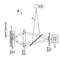
- Figure 2 is a diagram illustrating a prior art method for confocal autofocusing.
- Figure 3 is a diagram illustrating an exemplary autofocusing method according to an embodiment of the present invention.
- Figure 4 is a block diagram illustrating an exemplary microscope with an autofocusing function according to an embodiment of the present invention.
- Figure 5 is a close-up view of a pixel-based optical detector according to an embodiment of the present invention.
- Figure 6 is a flow chart illustrating an exemplary autofocusing method according to an embodiment of the present invention.
- Figure 7 illustrates another exemplary autofocusing method according to an embodiment of the present invention.
- Embodiments of the present invention introduce a new autofocusing technique that not only provides faster and more accurate focus adjustment than existing image-based autofocusing approaches, but does not require a separate detection system as in existing hardware-based autofocusing systems.
- a pixel-based optical detector that serves both as a microscope's main detector for image acquisition and as the detector for autofocus purpose.
- the pixel-based optical detector comprises a two-dimensional (2-D) array of sensor pixels whose detection data may be selectively accessed. That is, detection data associated with each sensor pixel in the 2-D array is capable of an independent readout and/or reset.
- CMOS complementary metal oxide semiconductor
- a suitable optical detector may be a,charge-coupled device (CCD) detector.
- the pixel-based optical detector is positioned in place of a physical confocal aperture and is programmed to emulate a virtual confocal aperture. Light intensity detected from sensor pixels located within the virtual confocal aperture is used as a basis for focus adjustments.
- FIG. 2 is a diagram illustrating a prior art method for confocal autofocusing.
- a light source 202 may generate a light beam 22.
- the light beam 22 may be focused by an objective lens 204 onto an object 24 and illuminate a point 26 on an object 24.
- An image of the point 26 may be formed on a confocal aperture 208. If the focal plane of the objective lens 204 coincides with the object plane 206, then light beams originating from the point 26 are in focus on the confocal aperture 208. These light beams may produce the highest light intensity and may be detected by an optical detector 210 located behind the confocal aperture 208.
- Focus adjustment for the optical system 200 may involve changing a relative position of the objective lens 204 to find the focal position that produces one of the peaks in the light intensity at the confocal aperture 208. See also JP2003 307681
- FIG. 3 is a diagram illustrating an exemplary autofocusing method according to an embodiment of the present invention.
- the exemplary method may be implemented with an autofocusing system 300.
- a light beam 32 generated by a light source 302, may pass through a beam-shaping element 303 that converts the light beam 32 into a light beam 33 that, after passing through an objective lens 304, forms a predefined illumination pattern (e.g., a point, a line, or a rectangular shape) on a object 34.
- a main difference from the prior art autofocusing system 200 shown in Figure 2
- the confocal aperture 208 may be emulated by a pixel-based optical detector 310 having a 2-D array of sensor pixels.
- the optical detector 310 may be positioned where the physical confocal aperture 208 used to be, wherein detection data associated with the sensor pixels may be selectively accessed.
- the illuminated pattern on the object 34 may form an image directly on the 2-D array of sensor pixels.
- the random access capability of the optical detector 310 may allow selective detection of incident light on the 2-D pixel array.
- a "virtual confocal aperture” may be flexibly emulated by designating a region of interest (ROI) in the array of sensor pixels. With the emulated confocal aperture, detection signals from those sensor pixels located outside the ROI may be reset to reject out-of-focus light.
- the shape of the virtual confocal aperture (or ROI) may be the same as or similar to the predefined pattern, and may be determined based on the operation mode of a microscope in which this exemplary method is implemented. For example, if the microscope operates in a point-confocal mode, the illuminated pattern and the ROI may be configured to have a point-like shape.
- the illuminated pattern and the ROI may be shaped into a line. Both the illuminated pattern and the ROI are typically centered in a field of view of the microscope.
- the size of the ROI may be the same as or smaller than the image of the illuminated pattern.
- a search for a desired focus may involve detection of light intensity from those sensor pixels located within the ROI together with a synchronized movement of the objective lens 304.
- An optimal focal position of the objective lens 304 may be identified as one that produces one of the peaks in the light intensity inside the virtual confocal aperture.
- Focus adjustment according to the exemplary method illustrated in Figure 3 may be faster than traditional image-based autofocusing systems for a number of reasons.
- the detection data may be read out fairly fast because, instead of collecting data from the entire sensor pixel array, only data from those sensor pixels within the ROI are read out.
- no extensive image processing is required.
- the exemplary method in Figure 3 does not require a separate optical detector or optical system to be dedicated to autofocusing.
- the autofocusing function may be implemented with the microscope's main image acquisition system.
- the autofocusing system 300 shown in Figure 3 may actually be a microscope's main image acquisition system as well.
- the optical detector 310 may be the main optical detector that also serves the autofocusing purposes.
- FIG. 4 is a block diagram illustrating an exemplary microscope 400 with an autofocusing function according to an embodiment of the present invention.
- the microscope 400 may comprise one or more light sources 402 that arc capable of generating one or more light beams either for image acquisition (e.g., fluorescence excitation) or for autofocusing.
- a light beam 40 may be selected from the one or more light sources 402 with, for example, an optical switch (not shown).
- the light beam 40 may pass through a beam-shaping module, which, in this example, is a line-forming module 404 that converts the light beam 40 into a light beam 42 diverging in the horizontal direction only.
- the light beam 42 may be directed by an optical element 406 (e.g., a dichroic mirror or a beam splitter) and then focused by an objective lens 408 to illuminate a line pattern 44 on an object 410.
- the line pattern 44 may be centered in the field of view of the microscope 400.
- Light reflecting off the object 410 may pass through the objective lens 408, the beam splitter 406 and a tube lens 412 before forming an image of the line pattern 44 on a pixel-based optical detector 414.
- FIG. 5 is a close-up view of the pixel-based optical detector 414 according to an embodiment of the present invention.
- the optical detector 414 may comprise a 2-D array of sensor pixels 502. Each sensor pixel may detect an optical signal incident thereon and have the resulting detection data read out or reset independently from the other sensor pixels.
- the illuminated line patter 44 may form an image covering a rectangular area 46 in the center of the optical detector 414. The size of the rectangular area 46 depends on overall magnification of the imaging system, and may vary depending on how focused the image is. The more focused the image is, the smaller the rectangular area 46 becomes.
- the size of the sharpest image of the line pattern 44 may be estimated and used as an upper limit to designate a region of interest (ROI) in the center of the optical detector 414.
- ROI region of interest
- the area 46 shown in Figure 5 represents approximately the smallest size observed for the image of the line pattern 44
- an array of sensor pixels of the same or smaller size than the area 46 may be designated as the ROI.
- either the rectangular area 46 or a slightly smaller rectangular area 48 may be selected to serve as a virtual confocal slit. Light intensity from those pixels located within the virtual confocal slit may be detected and analyzed, while detector data from pixels outside the virtual confocal slit may be either reset or ignored to reject out-of-focus light.
- the microscope 400 may further comprise a processor unit 416 which may be a microprocessor, microcontroller, a personal computer (PC), or similar electronic device. Coupled to the optical detector 414 and the objective lens 408, the processor unit 416 may coordinate the movement of the objective lens 408 with the detection of light intensity from the ROI in order to find a best focal position that corresponds to one of the highest light intensities detected. Instead of moving the objective lens 408, the object 410 may be moved with respect to the objective lens 408.
- a processor unit 416 may be a microprocessor, microcontroller, a personal computer (PC), or similar electronic device. Coupled to the optical detector 414 and the objective lens 408, the processor unit 416 may coordinate the movement of the objective lens 408 with the detection of light intensity from the ROI in order to find a best focal position that corresponds to one of the highest light intensities detected. Instead of moving the objective lens 408, the object 410 may be moved with respect to the objective lens 408.
- Figures 4 and 5 only show the major components in the microscope 400. In practice, more components may be desirable for more satisfactory operations of image acquisition and autofocusing.
- a preferred embodiment of an optical system for use in the microscope 400 may be found in a related U.S. Patent Application No. 11/184,444, filed on July 19, 2005 .
- Figure 6 is a flow chart illustrating an exemplary autofocusing method according to an embodiment of the present invention.
- an autofocus light beam may be coupled into the main optical path of an automated microscope.
- the automated microscope may have one or more main light sources for image acquisition.
- the autofocus light beam may be generated from a light source dedicated to autofocusing and may have a wavelength that is substantially different from the main light sources.
- the autofocus light beam may be generated from one of the main light sources.
- the autofocus light beam Before being coupled into the main optical path, the autofocus light beam may be shaped according to a predefined pattern. According to a preferred embodiment, the light beam may be expanded to form a horizontal line pattern.
- the autofocus light beam may be focused by an objective lens and may illuminate an object according to the predefined pattern.
- the autofocus light beam may be focused onto a horizontal line in the center of the microscope's field of view.
- the illuminated pattern on the object may form an image at a main optical detector of the microscope.
- the image of an illuminated line pattern is also shaped like a line.
- the line may be sharp or blurred depending on whether the illuminated line pattern is in focus or out of focus. If perfectly in focus, that is, the object plane coincides with the focal plane of the objective lens, the line may be the narrowest and the brightest. If out of focus to some extent, the line may be thicker and less bright.
- the main optical detector may have an array of sensor pixels that are amenable to selective or random data access.
- a region of interest (ROI) may be designated in the array of sensor pixels to emulate a confocal aperture.
- the ROI may be defined in such a way that it overlaps but is no larger than the sharpest image of the illuminated pattern. Therefore, for the illuminated line pattern centered in the field of view, the ROI may be chosen as a narrow and horizontally extending rectangular area centered in the array of sensor pixels.
- step 610 during autofocusing, light intensity may be detected from sensor pixels located within the ROI, while those sensor pixels outside the ROI may be reset.
- the relative position of the objective lens may be changed, in step 612, with respect to the object.
- the relative movement of the objective lens with respect to the object may involve moving the objective lens while keeping the object stationary, moving the object while keeping the objective lens stationary, or moving both the objective lens and the object.
- the steps 610 and 612 may be repeated such that, for each incremental position within a focus range, the corresponding light intensity in the ROI may be detected.
- a desired focal position of the objective lens may be selected for the microscope's image acquisition purposes. From the data collected in steps 610 and 612, a relationship of the changes in light intensity with respect to the relative position of the objective lens may be used as a basis for the search of a desired focal position. There may be one or more local maximums in the light intensity detected in the ROI. One of the local maximums may correspond to the best focal position of the objective lens. Other local maximums may be caused by strong reflections at, for example, an air-to-glass or glass-to-fluid interface. Thus, these local maximums may be used to identify the focal positions where the focal plane of the objective lens meets an interface in the object. One of the interfaces may be used as a reference for the focal position of the objective lens. For example, during image acquisition of the microscope, a predetermined offset may be applied to the movement of the objective lens or an object stage in order to bring a sample of interest to the focal plane of the objective lens.
- FIG. 7 illustrates another exemplary autofocusing method according to an embodiment of the present invention.
- the horizontally extending line pattern 44 may form a line-shaped image 74 on the optical detector 414.
- the ROI in this case may be designated as a vertically extending rectangular area 72.
- Both changes may be captured by the detection data collected from sensor pixels located within the rectangular area 72.
- the detection data may provide a light intensity distribution along the ROI.
- the line-shaped image 74 becomes more in focus, the light intensity becomes more concentrated in the center.
- the exemplary method illustrated in Figure 7 may provide more information associated with the focal position of the objective lens 408. For example, based on the width of the line-shaped image 74 and/or how fast the width changes, it may be predicted as to how far away the objective lens 408 is from its optimal focal position. Accordingly, the movement of the objective lens 408 may be sped up or slowed down. As a result, the search for the best focus may become faster and more accurate.
- the autofocusing technique in accordance with embodiments of the present invention may be adapted for a wide variety of microscopes.
- those skilled in the art may appreciate that the autofocusing technique disclosed herein may be applicable to both wide-field microscopes and confocal microscopes, and the microscopes may operate in either a fluorescence mode or a non-fluorescence mode.
Landscapes
- Physics & Mathematics (AREA)
- General Physics & Mathematics (AREA)
- Optics & Photonics (AREA)
- Chemical & Material Sciences (AREA)
- Analytical Chemistry (AREA)
- Engineering & Computer Science (AREA)
- Computer Vision & Pattern Recognition (AREA)
- Automatic Focus Adjustment (AREA)
- Microscoopes, Condenser (AREA)
Claims (14)
- Verfahren zur Einstellung des Fokus in einem automatisierten Mikroskop (400), umfassend:zumindest eine Lichtquelle, die einen Lichtstrahl (32, 40) erzeugt, ein Objektiv (304, 408),ein strahlformendes Element (303, 404), das eingerichtet ist, um den Lichtstrahl (32, 40) in einen Lichtstrahl (33, 42) umzuwandeln, der, nach Passieren des Objektivs (304, 408), ein vorab festgelegtes Beleuchtungsmuster (44) auf einem abzubildenden Objekt (34, 410) bildet,einen optischen Detektor (310, 414) in Form eines zweidimensionalen Arrays von Sensorpixeln (502), auf dessen Detektionsdaten selektiv zugegriffen werden kann, wobei der optische Detektor (310, 414) eingerichtet ist, um als Detektor für sowohl Bilderfassung als auch Autofokusdetektion zu dienen,einen optischen Pfad, der das Objektiv (304, 408) umfasst, das eingerichtet ist, um den Lichtstrahl (33, 42) auf eine Fokusebene zu fokussieren, um das vorab festgelegte Beleuchtungsmuster (44) auf dem Objekt (34, 410) zu bilden, und um ein Bild (46) des Beleuchtungsmusters am optischen Detektor (310, 414) zu bilden, wobei das Verfahren umfasst:Fokussieren des Lichtstrahls (33, 42) auf die Fokusebene, um das vorgegebene Beleuchtungsmuster (44) auf dem Objekt (34, 410) zu bilden;Bestimmen einer Region von Interesse (48) im Array von Sensorpixeln (502) zwecks Emulierens einer konfokalen Blende, durch selektives Zugreifen auf die Sensorpixel (502) in der Region von Interesse (48); wobei das Bild des Beleuchtungsmusters (46) die bestimmte Region von Interesse (48) im Wesentlichen überlappt;Detektieren der Lichtintensität aus Sensorpixeln (502), die sich innerhalb der bestimmten Region von Interesse (48) befinden; undEinstellen der Position der Fokusebene (306) in Bezug auf das Objekt (34, 410) (relative fokale Position) auf Grundlage der detektierten Lichtintensität.
- Verfahren nach Anspruch 1, das weiterhin umfasst:Auswählen, zwecks Bilderfassung, der relativen fokalen Position, die einem Peak in der detektierten Lichtintensität entspricht.
- Verfahren nach Anspruch 1, wobei der Schritt des Bestimmens der Region von Interesse (48) weiterhin umfasst:Kalibrieren der bestimmten Region von Interesse (48) so, dass ein schärfstes Bild des Beleuchtungsmusters (46) nicht kleiner als die bestimmte Region von Interesse (48) ist.
- Verfahren nach Anspruch 1, das weiterhin umfasst:Zurücksetzen oder Nichtberücksichtigen von Sensorpixeln (502), die sich außerhalb der bestimmten Region von Interesse befinden.
- Verfahren nach Anspruch 1, wobei:das automatisierte Mikroskop (400) in einem Linien-Konfokalmodus arbeitet;unddas vorab festgelegte Beleuchtungsmuster (44) die Form einer geraden Linie aufweist und in einem Bildfeld mittig ist.
- Verfahren nach Anspruch 1, wobei der optische Detektor (310, 414) aus einer Gruppe gewählt ist, die besteht aus:einem optischen CMOS-Detektor; undeiner CCD-Kamera.
- Verfahren nach Anspruch 1, wobei der Lichtstrahl (33, 42) fürs Autofokussieren bestimmt ist und eine Wellenlänge aufweist, die sich von jener einer Lichtquelle (402) unterscheidet, die vom automatisierten Mikroskop (400) zur Bilderfassung genutzt wird.
- Verfahren nach Anspruch 1, das weiterhin umfasst:Erkennen einer oder mehrerer Grenzflächen auf oder nahe dem Objekt (34, 410) durch Detektieren von Veränderungen der Lichtintensität während des Einstellens der relativen fokalen Position.
- Automatisiertes Mikroskop (400) zum Abbilden eines Objekts (34, 410), umfassend:zumindest eine Lichtquelle, die einen Lichtstrahl (32, 40) erzeugt;ein Objektiv (304, 408);ein strahlformendes Element (303, 404), das eingerichtet ist, um den Lichtstrahl (32, 40) zu einem Lichtstrahl (33, 42) umzuwandeln, der, nach Passieren des Objektivs (304, 408), ein vorab festgelegtes Beleuchtungsmuster (44) auf dem Objekt (34, 410) bildet;einen optischen Detektor (310, 414) in Form eines zweidimensionalen Arrays von Sensorpixeln (502);einen optischen Pfad, der das Objektiv (304, 408) umfasst, das eingerichtet ist, um den Lichtstrahl (33, 42) auf eine Fokusebene zu fokussieren, um das vorab festgelegte Beleuchtungsmuster (44) auf dem Objekt (34, 410) zu bilden, und um ein Bild (46) des Beleuchtungsmusters am optischen Detektor (310, 414) zu bilden;einen Bewegungsmechanismus, der in der Lage ist, die Position der Fokusebene (306) in Bezug auf das Objekt (34, 410) (relative fokale Position) einzustellen; undein Prozessormodul (416), das an den optischen Detektor und den Bewegungsmechanismus gekoppelt ist;dadurch gekennzeichnet, dass:auf die Detektionsdaten jedes Sensorpixels (502) selektiv zugegriffen werden kann;der optische Detektor (310, 414) eingerichtet ist, um als Detektor für sowohl Bilderfassung als auch Autofokusdetektion zu dienen;das Prozessormodul eingerichtet ist, um eine Region von Interesse (48) im Array von Sensorpixeln (502) zu bestimmen zwecks Emulierens einer konfokalen Blende, durch selektives Zugreifen auf die Sensorpixel (502) in der Region von Interesse (48); wobei das Bild des Beleuchtungsmusters (46) die bestimmte Region von Interesse (48) im Wesentlichen überlappt;das Prozessormodul (416) eingerichtet ist, um eine gewünschte relative fokale Position des Objektivs (304, 408) zu bestimmen durch Koordinieren der Einstellung der Position der Fokusebene (306) in Bezug auf das Objekt (34, 410) (relative fokale Position) und der Detektion von Lichtintensität aus Sensorpixeln (502), die sich innerhalb der bestimmten Region von Interesse (48) befinden.
- Automatisiertes Mikroskop (400) nach Anspruch 9, wobei das Prozessormodul (416) eingerichtet ist, um, zwecks Bilderfassung, die relative fokale Position auszuwählen, die einem Peak in der detektierten Lichtintensität entspricht.
- Automatisiertes Mikroskop (400) nach Anspruch 9, wobei das Prozessormodul (416) eingerichtet ist, um die bestimmte Region von Interesse (48) so zu kalibrieren, dass ein schärfstes Bild des Beleuchtungsmusters (46) nicht kleiner als die bestimmte Region von Interesse (48) ist.
- Automatisiertes Mikroskop (400) nach Anspruch 9, wobei das Prozessormodul (416) eingerichtet ist, um Sensorpixel zurückzusetzen oder nicht zu berücksichtigen, die sich außerhalb der bestimmten Region von Interesse (48) befinden.
- Automatisiertes Mikroskop (400) nach Anspruch 9, wobei der optische Detektor aus jener Gruppe gewählt ist, die besteht aus:einem optischen CMOS-Detektor; undeiner CCD-Kamera.
- Verfahren nach Anspruch 5, wobei
die bestimmte Region von Interesse (48) die Form einer geraden Linie hat, die sich quer zum Bild des Beleuchtungsmusters (46) erstreckt und dieses kreuzt.
Applications Claiming Priority (2)
| Application Number | Priority Date | Filing Date | Title |
|---|---|---|---|
| US11/320,676 US7297910B2 (en) | 2005-12-30 | 2005-12-30 | System and method for utilizing an autofocus feature in an automated microscope |
| PCT/US2006/062691 WO2007079397A2 (en) | 2005-12-30 | 2006-12-28 | Autofocus method and system for an automated microscope |
Publications (3)
| Publication Number | Publication Date |
|---|---|
| EP1969412A2 EP1969412A2 (de) | 2008-09-17 |
| EP1969412A4 EP1969412A4 (de) | 2010-11-10 |
| EP1969412B1 true EP1969412B1 (de) | 2013-03-06 |
Family
ID=38223406
Family Applications (1)
| Application Number | Title | Priority Date | Filing Date |
|---|---|---|---|
| EP06840357A Not-in-force EP1969412B1 (de) | 2005-12-30 | 2006-12-28 | Autofokus-verfahren und system für ein automatisiertes mikroskop |
Country Status (4)
| Country | Link |
|---|---|
| US (2) | US7297910B2 (de) |
| EP (1) | EP1969412B1 (de) |
| JP (1) | JP5015955B2 (de) |
| WO (1) | WO2007079397A2 (de) |
Cited By (1)
| Publication number | Priority date | Publication date | Assignee | Title |
|---|---|---|---|---|
| US10598915B2 (en) | 2014-06-23 | 2020-03-24 | Perkinelmer Cellular Technologies Germany Gmbh | Method for autofocusing a microscope at a correct autofocus position in a sample |
Families Citing this family (46)
| Publication number | Priority date | Publication date | Assignee | Title |
|---|---|---|---|---|
| WO2007095387A2 (en) | 2006-02-17 | 2007-08-23 | Dharmacon, Inc. | Compositions and methods for inhibiting gene silencing by rna interference |
| KR20090018711A (ko) * | 2006-06-09 | 2009-02-20 | 위구-디바이스 아이엔씨. | 무한 보정 현미경의 자동 포커싱을 위한 방법 및 장치 |
| JP2008052140A (ja) * | 2006-08-25 | 2008-03-06 | Olympus Corp | 観察装置 |
| JP5172204B2 (ja) * | 2007-05-16 | 2013-03-27 | 大塚電子株式会社 | 光学特性測定装置およびフォーカス調整方法 |
| DE102008018951A1 (de) * | 2008-04-15 | 2009-10-22 | Carl Zeiss Microimaging Gmbh | Mikroskop mit Haltefokuseinheit |
| JP5306041B2 (ja) * | 2008-05-08 | 2013-10-02 | キヤノン株式会社 | 撮像装置及びその方法 |
| ES2617664T3 (es) | 2009-03-11 | 2017-06-19 | Sakura Finetek U.S.A., Inc. | Procedimiento de enfoque automático y dispositivo de enfoque automático |
| ES2561937T3 (es) | 2009-12-30 | 2016-03-01 | Koninklijke Philips N.V. | Sensor para microscopia |
| DE102017203492A1 (de) * | 2017-03-03 | 2018-09-06 | Witec Wissenschaftliche Instrumente Und Technologie Gmbh | Verfahren und Vorrichtung zur Abbildung einer Probenoberfläche |
| CN102893198B (zh) * | 2010-05-18 | 2015-11-25 | 皇家飞利浦电子股份有限公司 | 自动聚焦成像系统、成像方法及显微镜 |
| TWI456254B (zh) * | 2010-05-19 | 2014-10-11 | Ind Tech Res Inst | 螢光顯微影像系統 |
| CN103038692B (zh) * | 2010-06-24 | 2015-12-16 | 皇家飞利浦电子股份有限公司 | 基于差分测量的自动聚焦 |
| DE102010055882A1 (de) * | 2010-12-22 | 2012-06-28 | Carl Zeiss Microlmaging Gmbh | Pinhole für ein konfokales Laser-Scanning Mikroskop |
| CN103649992B (zh) | 2011-07-13 | 2017-12-26 | 皇家飞利浦有限公司 | 用于自动调节数字病理图像的焦平面的方法 |
| DE102011084562B4 (de) * | 2011-10-14 | 2018-02-15 | Leica Microsystems Cms Gmbh | Verfahren und Vorrichtung zur Feststellung und Korrektur von sphärischen Abbildungsfehlern in einem mikroskopischen Abbildungsstrahlengang |
| US10591501B2 (en) * | 2011-10-31 | 2020-03-17 | Torsten Matthias | Automatic structure determination |
| JP5932376B2 (ja) * | 2012-02-08 | 2016-06-08 | 富士機械製造株式会社 | 画像転送方法および画像転送装置 |
| US8687180B2 (en) * | 2012-06-07 | 2014-04-01 | Molecular Devices, Llc | System, method, and device for determining a focal position of an objective in a microscopy imaging system |
| RU2515341C2 (ru) * | 2012-08-20 | 2014-05-10 | Федеральное государственное бюджетное образовательное учреждение высшего профессионального образования "Московский государственный технический университет радиотехники, электроники и автоматики" | Двухфотонный сканирующий микроскоп с автоматической точной фокусировкой изображения и способ автоматической точной фокусировки изображения |
| US9488819B2 (en) * | 2012-08-31 | 2016-11-08 | Nanotronics Imaging, Inc. | Automatic microscopic focus system and method for analysis of transparent or low contrast specimens |
| JP6205140B2 (ja) * | 2013-03-01 | 2017-09-27 | オリンパス株式会社 | 走査型レーザ顕微鏡装置 |
| DE102013103971A1 (de) | 2013-04-19 | 2014-11-06 | Sensovation Ag | Verfahren zum Erzeugen eines aus mehreren Teilbildern zusammengesetzten Gesamtbilds eines Objekts |
| US9661212B2 (en) | 2013-04-26 | 2017-05-23 | Hamamatsu Photonics K.K. | Image acquisition device and focusing method for image acquisition device |
| EP2990849B1 (de) | 2013-04-26 | 2020-09-02 | Hamamatsu Photonics K.K. | Bilderfassungsvorrichtung und verfahren und system zur erzeugung einer fokuskarte für proben |
| JP6433888B2 (ja) | 2013-04-26 | 2018-12-05 | 浜松ホトニクス株式会社 | 画像取得装置、試料の合焦点情報を取得する方法及びシステム |
| WO2014179269A2 (en) * | 2013-04-30 | 2014-11-06 | Molecular Devices, Llc | Apparatus and method for generating in-focus images using parallel imaging in a microscopy system |
| US10007102B2 (en) | 2013-12-23 | 2018-06-26 | Sakura Finetek U.S.A., Inc. | Microscope with slide clamping assembly |
| JP6865680B2 (ja) * | 2014-10-06 | 2021-04-28 | ライカ マイクロシステムズ (シュヴァイツ) アクチエンゲゼルシャフトLeica Microsystems (Schweiz) AG | 顕微鏡 |
| JP6805135B2 (ja) * | 2014-10-06 | 2020-12-23 | ライカ マイクロシステムズ (シュヴァイツ) アクチエンゲゼルシャフトLeica Microsystems (Schweiz) AG | 顕微鏡 |
| US9921399B2 (en) | 2015-03-31 | 2018-03-20 | General Electric Company | System and method for continuous, asynchronous autofocus of optical instruments |
| CN104932092B (zh) * | 2015-06-15 | 2017-09-08 | 上海交通大学 | 基于偏心光束法的自动对焦显微镜及其对焦方法 |
| US9772540B2 (en) * | 2015-07-09 | 2017-09-26 | Bio-Tek Instruments, Inc. | Autofocus for imaging system |
| DE102015116452A1 (de) | 2015-09-29 | 2017-03-30 | Carl Zeiss Microscopy Gmbh | Mikroskop |
| DE102016108226A1 (de) | 2016-05-03 | 2017-11-09 | Carl Zeiss Microscopy Gmbh | Mikroskop |
| US11280803B2 (en) | 2016-11-22 | 2022-03-22 | Sakura Finetek U.S.A., Inc. | Slide management system |
| CN106707482A (zh) * | 2017-02-28 | 2017-05-24 | 浙江大学 | 一种宽视场多尺度高分辨率显微成像系统和方法 |
| EP3418789A1 (de) * | 2017-06-20 | 2018-12-26 | Euroimmun Medizinische Labordiagnostika AG | Verfahren und mikroskopiesystem zum aufnehmen eines bildes |
| TWI659227B (zh) | 2017-06-20 | 2019-05-11 | Academia Sinica | 以影像導引之顯微照射的顯微鏡系統及方法 |
| US10989903B2 (en) * | 2018-02-26 | 2021-04-27 | Washington State University | Modular scanning confocal optical profile microscopy with digital imaging processing |
| US10247910B1 (en) | 2018-03-14 | 2019-04-02 | Nanotronics Imaging, Inc. | Systems, devices and methods for automatic microscopic focus |
| US10146041B1 (en) | 2018-05-01 | 2018-12-04 | Nanotronics Imaging, Inc. | Systems, devices and methods for automatic microscope focus |
| EP3614192A1 (de) * | 2018-08-20 | 2020-02-26 | Till GmbH | Mikroskopvorrichtung |
| WO2020207571A1 (en) * | 2019-04-09 | 2020-10-15 | Carl Zeiss Microscopy Gmbh | Light microscope with reconfigurable sensor array |
| US11402331B2 (en) * | 2019-05-08 | 2022-08-02 | City University Of Hong Kong | Imaging and manipulation of biological sample |
| WO2020240639A1 (ja) * | 2019-05-24 | 2020-12-03 | 株式会社ニコン | 顕微鏡装置、顕微鏡装置の制御方法、および顕微鏡装置の制御プログラム |
| JP7852370B2 (ja) * | 2022-04-22 | 2026-04-28 | 横河電機株式会社 | 情報処理装置、情報処理システム、情報処理方法および情報処理プログラム |
Family Cites Families (22)
| Publication number | Priority date | Publication date | Assignee | Title |
|---|---|---|---|---|
| DD240611A1 (de) * | 1985-09-02 | 1986-11-05 | Zeiss Jena Veb Carl | Verfahren zur einstellung der fokussierung in optischen einrichtungen |
| DE68928217T2 (de) * | 1988-09-09 | 1998-01-29 | Canon Kk | Automatische Bildstabilisierungsvorrichtung |
| US5774444A (en) * | 1990-05-25 | 1998-06-30 | Hitachi, Ltd. | Split photo detector for detecting a central portion and a peripheral portion of a reflected light beam |
| EP0542962B2 (de) * | 1991-06-08 | 2002-03-13 | RENISHAW plc | Konfokale spektroskopie |
| JPH08327891A (ja) * | 1995-06-02 | 1996-12-13 | Olympus Optical Co Ltd | パターン光投光装置 |
| JPH09133856A (ja) * | 1995-11-07 | 1997-05-20 | Nikon Corp | 顕微鏡用自動焦点検出装置 |
| JP3579166B2 (ja) * | 1996-02-14 | 2004-10-20 | オリンパス株式会社 | 走査型レーザ顕微鏡 |
| JPH1164719A (ja) * | 1997-08-22 | 1999-03-05 | Nikon Corp | 焦点検出手段を備えた顕微鏡および変位計測装置 |
| JPH11142716A (ja) * | 1997-11-04 | 1999-05-28 | Nikon Corp | 焦点検出装置 |
| US20020050518A1 (en) * | 1997-12-08 | 2002-05-02 | Roustaei Alexander R. | Sensor array |
| US6677565B1 (en) * | 1998-08-18 | 2004-01-13 | Veeco Tucson Inc. | High speed autofocus and tilt for an optical imaging system |
| US6819639B1 (en) * | 1999-07-15 | 2004-11-16 | Creo Srl | Method and apparatus for multi-channel auto-focus |
| US6792203B1 (en) * | 1999-09-01 | 2004-09-14 | Olympus Optical Co., Ltd. | Camera and distance measuring apparatus used in the same |
| JP3688185B2 (ja) * | 2000-05-08 | 2005-08-24 | 株式会社東京精密 | 焦点検出装置及び自動焦点顕微鏡 |
| JP2002258160A (ja) * | 2001-03-05 | 2002-09-11 | Dainippon Printing Co Ltd | 共焦点型レーザー顕微鏡における合焦点位置判定方法および測定対象物の表面の高さ測定方法 |
| JP2002287017A (ja) * | 2001-03-28 | 2002-10-03 | Fuji Photo Optical Co Ltd | 撮影レンズのピント状態検出装置 |
| DE10127284A1 (de) * | 2001-06-05 | 2002-12-12 | Zeiss Carl Jena Gmbh | Autofokussiereinrichtung für ein optisches Gerät |
| JP4179790B2 (ja) * | 2002-04-17 | 2008-11-12 | オリンパス株式会社 | 共焦点走査型光学顕微鏡 |
| JP2004191893A (ja) * | 2002-12-13 | 2004-07-08 | Canon Inc | 撮像装置 |
| US20040140417A1 (en) * | 2002-12-27 | 2004-07-22 | Accretech (Israel) Ltd. | Image sensor for confocal microscopy |
| US7232980B2 (en) * | 2004-05-24 | 2007-06-19 | Hamamatsu Photonics K.K. | Microscope system |
| JP4551708B2 (ja) * | 2004-07-21 | 2010-09-29 | キヤノン株式会社 | 撮像装置 |
-
2005
- 2005-12-30 US US11/320,676 patent/US7297910B2/en not_active Expired - Lifetime
-
2006
- 2006-12-28 WO PCT/US2006/062691 patent/WO2007079397A2/en not_active Ceased
- 2006-12-28 JP JP2008548860A patent/JP5015955B2/ja not_active Expired - Fee Related
- 2006-12-28 EP EP06840357A patent/EP1969412B1/de not_active Not-in-force
-
2007
- 2007-10-31 US US11/930,206 patent/US7473877B2/en not_active Expired - Lifetime
Cited By (1)
| Publication number | Priority date | Publication date | Assignee | Title |
|---|---|---|---|---|
| US10598915B2 (en) | 2014-06-23 | 2020-03-24 | Perkinelmer Cellular Technologies Germany Gmbh | Method for autofocusing a microscope at a correct autofocus position in a sample |
Also Published As
| Publication number | Publication date |
|---|---|
| US20080054156A1 (en) | 2008-03-06 |
| US7297910B2 (en) | 2007-11-20 |
| US7473877B2 (en) | 2009-01-06 |
| JP2009522604A (ja) | 2009-06-11 |
| WO2007079397A3 (en) | 2007-11-01 |
| JP5015955B2 (ja) | 2012-09-05 |
| EP1969412A4 (de) | 2010-11-10 |
| US20070152130A1 (en) | 2007-07-05 |
| EP1969412A2 (de) | 2008-09-17 |
| WO2007079397A2 (en) | 2007-07-12 |
Similar Documents
| Publication | Publication Date | Title |
|---|---|---|
| EP1969412B1 (de) | Autofokus-verfahren und system für ein automatisiertes mikroskop | |
| JP7609804B2 (ja) | 無限遠補正顕微鏡のための自己較正および方向集束のシステムおよび方法 | |
| US8179432B2 (en) | Predictive autofocusing | |
| US8878923B2 (en) | System and method for enhanced predictive autofocusing | |
| US7576307B2 (en) | Microscope with dual image sensors for rapid autofocusing | |
| CN101031837B (zh) | 用于荧光共焦显微镜检查的方法和设备 | |
| US5604344A (en) | Autofocussing microscope having a pattern imaging system | |
| US20180191948A1 (en) | Single-Frame Autofocusing Using Multi-LED Illumination | |
| US10838184B2 (en) | Artefact reduction for angularly-selective illumination | |
| JPH11211439A (ja) | 表面形状計測装置 | |
| JP5053691B2 (ja) | 標本スキャナ装置、該装置による標本位置検出方法 | |
| WO2016132451A1 (ja) | 顕微鏡 | |
| JP2004102032A (ja) | 走査型共焦点顕微鏡装置 | |
| JP2023078801A (ja) | 顕微鏡システム、及び、顕微鏡制御装置 | |
| KR102959533B1 (ko) | 현미경의 시야 조리개 영상을 이용한 패턴 없는 시료의 자동 초점 및 기울어짐을 제어하는 장치 및 방법 | |
| US20250146949A1 (en) | Machine vision system utilizing autofocus and inspection processes | |
| US20260079335A1 (en) | Metrology system utilizing scan lens for points-from-focus type processes | |
| KR20040108144A (ko) | 슬릿빔을 이용한 현미경의 자동초점조절장치 |
Legal Events
| Date | Code | Title | Description |
|---|---|---|---|
| PUAI | Public reference made under article 153(3) epc to a published international application that has entered the european phase |
Free format text: ORIGINAL CODE: 0009012 |
|
| 17P | Request for examination filed |
Effective date: 20080721 |
|
| AK | Designated contracting states |
Kind code of ref document: A2 Designated state(s): AT BE BG CH CY CZ DE DK EE ES FI FR GB GR HU IE IS IT LI LT LU LV MC NL PL PT RO SE SI SK TR |
|
| A4 | Supplementary search report drawn up and despatched |
Effective date: 20101011 |
|
| 17Q | First examination report despatched |
Effective date: 20111025 |
|
| DAX | Request for extension of the european patent (deleted) | ||
| GRAP | Despatch of communication of intention to grant a patent |
Free format text: ORIGINAL CODE: EPIDOSNIGR1 |
|
| GRAS | Grant fee paid |
Free format text: ORIGINAL CODE: EPIDOSNIGR3 |
|
| GRAA | (expected) grant |
Free format text: ORIGINAL CODE: 0009210 |
|
| AK | Designated contracting states |
Kind code of ref document: B1 Designated state(s): AT BE BG CH CY CZ DE DK EE ES FI FR GB GR HU IE IS IT LI LT LU LV MC NL PL PT RO SE SI SK TR |
|
| REG | Reference to a national code |
Ref country code: GB Ref legal event code: FG4D |
|
| REG | Reference to a national code |
Ref country code: CH Ref legal event code: EP Ref country code: AT Ref legal event code: REF Ref document number: 599950 Country of ref document: AT Kind code of ref document: T Effective date: 20130315 |
|
| REG | Reference to a national code |
Ref country code: IE Ref legal event code: FG4D |
|
| REG | Reference to a national code |
Ref country code: DE Ref legal event code: R096 Ref document number: 602006034962 Country of ref document: DE Effective date: 20130425 |
|
| RAP4 | Party data changed (patent owner data changed or rights of a patent transferred) |
Owner name: GENERAL ELECTRIC COMPANY |
|
| REG | Reference to a national code |
Ref country code: AT Ref legal event code: MK05 Ref document number: 599950 Country of ref document: AT Kind code of ref document: T Effective date: 20130306 |
|
| PG25 | Lapsed in a contracting state [announced via postgrant information from national office to epo] |
Ref country code: SE Free format text: LAPSE BECAUSE OF FAILURE TO SUBMIT A TRANSLATION OF THE DESCRIPTION OR TO PAY THE FEE WITHIN THE PRESCRIBED TIME-LIMIT Effective date: 20130306 Ref country code: AT Free format text: LAPSE BECAUSE OF FAILURE TO SUBMIT A TRANSLATION OF THE DESCRIPTION OR TO PAY THE FEE WITHIN THE PRESCRIBED TIME-LIMIT Effective date: 20130306 Ref country code: ES Free format text: LAPSE BECAUSE OF FAILURE TO SUBMIT A TRANSLATION OF THE DESCRIPTION OR TO PAY THE FEE WITHIN THE PRESCRIBED TIME-LIMIT Effective date: 20130617 Ref country code: BG Free format text: LAPSE BECAUSE OF FAILURE TO SUBMIT A TRANSLATION OF THE DESCRIPTION OR TO PAY THE FEE WITHIN THE PRESCRIBED TIME-LIMIT Effective date: 20130606 Ref country code: LT Free format text: LAPSE BECAUSE OF FAILURE TO SUBMIT A TRANSLATION OF THE DESCRIPTION OR TO PAY THE FEE WITHIN THE PRESCRIBED TIME-LIMIT Effective date: 20130306 |
|
| REG | Reference to a national code |
Ref country code: NL Ref legal event code: VDEP Effective date: 20130306 |
|
| REG | Reference to a national code |
Ref country code: LT Ref legal event code: MG4D |
|
| PG25 | Lapsed in a contracting state [announced via postgrant information from national office to epo] |
Ref country code: SI Free format text: LAPSE BECAUSE OF FAILURE TO SUBMIT A TRANSLATION OF THE DESCRIPTION OR TO PAY THE FEE WITHIN THE PRESCRIBED TIME-LIMIT Effective date: 20130306 Ref country code: GR Free format text: LAPSE BECAUSE OF FAILURE TO SUBMIT A TRANSLATION OF THE DESCRIPTION OR TO PAY THE FEE WITHIN THE PRESCRIBED TIME-LIMIT Effective date: 20130607 Ref country code: FI Free format text: LAPSE BECAUSE OF FAILURE TO SUBMIT A TRANSLATION OF THE DESCRIPTION OR TO PAY THE FEE WITHIN THE PRESCRIBED TIME-LIMIT Effective date: 20130306 Ref country code: LV Free format text: LAPSE BECAUSE OF FAILURE TO SUBMIT A TRANSLATION OF THE DESCRIPTION OR TO PAY THE FEE WITHIN THE PRESCRIBED TIME-LIMIT Effective date: 20130306 |
|
| PG25 | Lapsed in a contracting state [announced via postgrant information from national office to epo] |
Ref country code: BE Free format text: LAPSE BECAUSE OF FAILURE TO SUBMIT A TRANSLATION OF THE DESCRIPTION OR TO PAY THE FEE WITHIN THE PRESCRIBED TIME-LIMIT Effective date: 20130306 |
|
| PG25 | Lapsed in a contracting state [announced via postgrant information from national office to epo] |
Ref country code: EE Free format text: LAPSE BECAUSE OF FAILURE TO SUBMIT A TRANSLATION OF THE DESCRIPTION OR TO PAY THE FEE WITHIN THE PRESCRIBED TIME-LIMIT Effective date: 20130306 Ref country code: PT Free format text: LAPSE BECAUSE OF FAILURE TO SUBMIT A TRANSLATION OF THE DESCRIPTION OR TO PAY THE FEE WITHIN THE PRESCRIBED TIME-LIMIT Effective date: 20130708 Ref country code: RO Free format text: LAPSE BECAUSE OF FAILURE TO SUBMIT A TRANSLATION OF THE DESCRIPTION OR TO PAY THE FEE WITHIN THE PRESCRIBED TIME-LIMIT Effective date: 20130306 Ref country code: IS Free format text: LAPSE BECAUSE OF FAILURE TO SUBMIT A TRANSLATION OF THE DESCRIPTION OR TO PAY THE FEE WITHIN THE PRESCRIBED TIME-LIMIT Effective date: 20130706 Ref country code: NL Free format text: LAPSE BECAUSE OF FAILURE TO SUBMIT A TRANSLATION OF THE DESCRIPTION OR TO PAY THE FEE WITHIN THE PRESCRIBED TIME-LIMIT Effective date: 20130306 Ref country code: CZ Free format text: LAPSE BECAUSE OF FAILURE TO SUBMIT A TRANSLATION OF THE DESCRIPTION OR TO PAY THE FEE WITHIN THE PRESCRIBED TIME-LIMIT Effective date: 20130306 Ref country code: SK Free format text: LAPSE BECAUSE OF FAILURE TO SUBMIT A TRANSLATION OF THE DESCRIPTION OR TO PAY THE FEE WITHIN THE PRESCRIBED TIME-LIMIT Effective date: 20130306 |
|
| PG25 | Lapsed in a contracting state [announced via postgrant information from national office to epo] |
Ref country code: PL Free format text: LAPSE BECAUSE OF FAILURE TO SUBMIT A TRANSLATION OF THE DESCRIPTION OR TO PAY THE FEE WITHIN THE PRESCRIBED TIME-LIMIT Effective date: 20130306 Ref country code: CY Free format text: LAPSE BECAUSE OF FAILURE TO SUBMIT A TRANSLATION OF THE DESCRIPTION OR TO PAY THE FEE WITHIN THE PRESCRIBED TIME-LIMIT Effective date: 20130306 |
|
| PLBE | No opposition filed within time limit |
Free format text: ORIGINAL CODE: 0009261 |
|
| STAA | Information on the status of an ep patent application or granted ep patent |
Free format text: STATUS: NO OPPOSITION FILED WITHIN TIME LIMIT |
|
| PG25 | Lapsed in a contracting state [announced via postgrant information from national office to epo] |
Ref country code: DK Free format text: LAPSE BECAUSE OF FAILURE TO SUBMIT A TRANSLATION OF THE DESCRIPTION OR TO PAY THE FEE WITHIN THE PRESCRIBED TIME-LIMIT Effective date: 20130306 |
|
| 26N | No opposition filed |
Effective date: 20131209 |
|
| PG25 | Lapsed in a contracting state [announced via postgrant information from national office to epo] |
Ref country code: IT Free format text: LAPSE BECAUSE OF FAILURE TO SUBMIT A TRANSLATION OF THE DESCRIPTION OR TO PAY THE FEE WITHIN THE PRESCRIBED TIME-LIMIT Effective date: 20130306 |
|
| REG | Reference to a national code |
Ref country code: DE Ref legal event code: R097 Ref document number: 602006034962 Country of ref document: DE Effective date: 20131209 |
|
| REG | Reference to a national code |
Ref country code: DE Ref legal event code: R119 Ref document number: 602006034962 Country of ref document: DE |
|
| REG | Reference to a national code |
Ref country code: CH Ref legal event code: PL |
|
| GBPC | Gb: european patent ceased through non-payment of renewal fee |
Effective date: 20131228 |
|
| PG25 | Lapsed in a contracting state [announced via postgrant information from national office to epo] |
Ref country code: MC Free format text: LAPSE BECAUSE OF FAILURE TO SUBMIT A TRANSLATION OF THE DESCRIPTION OR TO PAY THE FEE WITHIN THE PRESCRIBED TIME-LIMIT Effective date: 20130306 Ref country code: LU Free format text: LAPSE BECAUSE OF FAILURE TO SUBMIT A TRANSLATION OF THE DESCRIPTION OR TO PAY THE FEE WITHIN THE PRESCRIBED TIME-LIMIT Effective date: 20131228 |
|
| REG | Reference to a national code |
Ref country code: IE Ref legal event code: MM4A |
|
| REG | Reference to a national code |
Ref country code: DE Ref legal event code: R119 Ref document number: 602006034962 Country of ref document: DE Effective date: 20140701 |
|
| REG | Reference to a national code |
Ref country code: FR Ref legal event code: ST Effective date: 20140829 |
|
| PG25 | Lapsed in a contracting state [announced via postgrant information from national office to epo] |
Ref country code: DE Free format text: LAPSE BECAUSE OF NON-PAYMENT OF DUE FEES Effective date: 20140701 Ref country code: IE Free format text: LAPSE BECAUSE OF NON-PAYMENT OF DUE FEES Effective date: 20131228 Ref country code: CH Free format text: LAPSE BECAUSE OF NON-PAYMENT OF DUE FEES Effective date: 20131231 Ref country code: LI Free format text: LAPSE BECAUSE OF NON-PAYMENT OF DUE FEES Effective date: 20131231 |
|
| PG25 | Lapsed in a contracting state [announced via postgrant information from national office to epo] |
Ref country code: GB Free format text: LAPSE BECAUSE OF NON-PAYMENT OF DUE FEES Effective date: 20131228 Ref country code: FR Free format text: LAPSE BECAUSE OF NON-PAYMENT OF DUE FEES Effective date: 20131231 |
|
| PG25 | Lapsed in a contracting state [announced via postgrant information from national office to epo] |
Ref country code: TR Free format text: LAPSE BECAUSE OF FAILURE TO SUBMIT A TRANSLATION OF THE DESCRIPTION OR TO PAY THE FEE WITHIN THE PRESCRIBED TIME-LIMIT Effective date: 20130306 |
|
| PG25 | Lapsed in a contracting state [announced via postgrant information from national office to epo] |
Ref country code: HU Free format text: LAPSE BECAUSE OF FAILURE TO SUBMIT A TRANSLATION OF THE DESCRIPTION OR TO PAY THE FEE WITHIN THE PRESCRIBED TIME-LIMIT; INVALID AB INITIO Effective date: 20061228 |