EP1968327A2 - Décodeur de vidéos MPEG et procédé de décodage de vidéos MPEG - Google Patents
Décodeur de vidéos MPEG et procédé de décodage de vidéos MPEG Download PDFInfo
- Publication number
- EP1968327A2 EP1968327A2 EP20080157947 EP08157947A EP1968327A2 EP 1968327 A2 EP1968327 A2 EP 1968327A2 EP 20080157947 EP20080157947 EP 20080157947 EP 08157947 A EP08157947 A EP 08157947A EP 1968327 A2 EP1968327 A2 EP 1968327A2
- Authority
- EP
- European Patent Office
- Prior art keywords
- decoding
- picture
- display
- control section
- register
- Prior art date
- Legal status (The legal status is an assumption and is not a legal conclusion. Google has not performed a legal analysis and makes no representation as to the accuracy of the status listed.)
- Withdrawn
Links
Images









Classifications
-
- H—ELECTRICITY
- H04—ELECTRIC COMMUNICATION TECHNIQUE
- H04N—PICTORIAL COMMUNICATION, e.g. TELEVISION
- H04N19/00—Methods or arrangements for coding, decoding, compressing or decompressing digital video signals
- H04N19/90—Methods or arrangements for coding, decoding, compressing or decompressing digital video signals using coding techniques not provided for in groups H04N19/10-H04N19/85, e.g. fractals
-
- H—ELECTRICITY
- H04—ELECTRIC COMMUNICATION TECHNIQUE
- H04N—PICTORIAL COMMUNICATION, e.g. TELEVISION
- H04N19/00—Methods or arrangements for coding, decoding, compressing or decompressing digital video signals
- H04N19/10—Methods or arrangements for coding, decoding, compressing or decompressing digital video signals using adaptive coding
- H04N19/102—Methods or arrangements for coding, decoding, compressing or decompressing digital video signals using adaptive coding characterised by the element, parameter or selection affected or controlled by the adaptive coding
- H04N19/127—Prioritisation of hardware or computational resources
-
- H—ELECTRICITY
- H04—ELECTRIC COMMUNICATION TECHNIQUE
- H04N—PICTORIAL COMMUNICATION, e.g. TELEVISION
- H04N19/00—Methods or arrangements for coding, decoding, compressing or decompressing digital video signals
- H04N19/10—Methods or arrangements for coding, decoding, compressing or decompressing digital video signals using adaptive coding
- H04N19/134—Methods or arrangements for coding, decoding, compressing or decompressing digital video signals using adaptive coding characterised by the element, parameter or criterion affecting or controlling the adaptive coding
- H04N19/146—Data rate or code amount at the encoder output
- H04N19/152—Data rate or code amount at the encoder output by measuring the fullness of the transmission buffer
-
- H—ELECTRICITY
- H04—ELECTRIC COMMUNICATION TECHNIQUE
- H04N—PICTORIAL COMMUNICATION, e.g. TELEVISION
- H04N19/00—Methods or arrangements for coding, decoding, compressing or decompressing digital video signals
- H04N19/10—Methods or arrangements for coding, decoding, compressing or decompressing digital video signals using adaptive coding
- H04N19/169—Methods or arrangements for coding, decoding, compressing or decompressing digital video signals using adaptive coding characterised by the coding unit, i.e. the structural portion or semantic portion of the video signal being the object or the subject of the adaptive coding
- H04N19/17—Methods or arrangements for coding, decoding, compressing or decompressing digital video signals using adaptive coding characterised by the coding unit, i.e. the structural portion or semantic portion of the video signal being the object or the subject of the adaptive coding the unit being an image region, e.g. an object
- H04N19/172—Methods or arrangements for coding, decoding, compressing or decompressing digital video signals using adaptive coding characterised by the coding unit, i.e. the structural portion or semantic portion of the video signal being the object or the subject of the adaptive coding the unit being an image region, e.g. an object the region being a picture, frame or field
-
- H—ELECTRICITY
- H04—ELECTRIC COMMUNICATION TECHNIQUE
- H04N—PICTORIAL COMMUNICATION, e.g. TELEVISION
- H04N19/00—Methods or arrangements for coding, decoding, compressing or decompressing digital video signals
- H04N19/42—Methods or arrangements for coding, decoding, compressing or decompressing digital video signals characterised by implementation details or hardware specially adapted for video compression or decompression, e.g. dedicated software implementation
- H04N19/423—Methods or arrangements for coding, decoding, compressing or decompressing digital video signals characterised by implementation details or hardware specially adapted for video compression or decompression, e.g. dedicated software implementation characterised by memory arrangements
-
- H—ELECTRICITY
- H04—ELECTRIC COMMUNICATION TECHNIQUE
- H04N—PICTORIAL COMMUNICATION, e.g. TELEVISION
- H04N19/00—Methods or arrangements for coding, decoding, compressing or decompressing digital video signals
- H04N19/44—Decoders specially adapted therefor, e.g. video decoders which are asymmetric with respect to the encoder
-
- H—ELECTRICITY
- H04—ELECTRIC COMMUNICATION TECHNIQUE
- H04N—PICTORIAL COMMUNICATION, e.g. TELEVISION
- H04N19/00—Methods or arrangements for coding, decoding, compressing or decompressing digital video signals
- H04N19/60—Methods or arrangements for coding, decoding, compressing or decompressing digital video signals using transform coding
- H04N19/61—Methods or arrangements for coding, decoding, compressing or decompressing digital video signals using transform coding in combination with predictive coding
-
- H—ELECTRICITY
- H04—ELECTRIC COMMUNICATION TECHNIQUE
- H04N—PICTORIAL COMMUNICATION, e.g. TELEVISION
- H04N19/00—Methods or arrangements for coding, decoding, compressing or decompressing digital video signals
- H04N19/50—Methods or arrangements for coding, decoding, compressing or decompressing digital video signals using predictive coding
Definitions
- the present invention relates to an MPEG video decoder for decoding a bit-stream which has been encoded according to a Moving Picture Expert Group (hereinafter, referred to as an MPEG) standard, and an MPEG video decoding method.
- MPEG Moving Picture Expert Group
- the MPEG standard has been heretofore employed as an international standard for bit rate reduction of picture data.
- a moving picture encoding technology and a moving picture decoding technology, which are in conformity with the MPEG standard, are much used for recent multi-media environments.
- Many moving picture encoding apparatus and moving picture decoding apparatus which adopt the MPEG standard have been developed.
- a bit rate reduction encoding by the MPEG standard includes a constant bit rate encoding (hereinafter, referred to as a CBR encoding) in which a data rate after encoding is substantially constant and a variable bit rate encoding (hereinafter, referred to as a VBR encoding) in which the data rate after encoding is not constant.
- CBR encoding constant bit rate encoding
- VBR encoding variable bit rate encoding
- the CBR encoding is used when a transmission line is in a STM mode (Synchronous Transfer Mode).
- the VBR encoding is used when the transmission line in an ATM mode (Asynchronous Transfer Mode), as well as when the transmission line is storage media such as a DVD (Digital Video Disc).
- Fig. 4 of the accompanying drawings is a figure schematically showing the telecine conversion by the 3-2 pull down.
- the symbol * represents the repetition of the image, similarly.
- the symbol *' represents the repetition of the same image by the repeat first field.
- a TV video for one second consists of an image for 60 fields.
- the repeat first field command is added to 12 frames among 24 frames, and the picture data for 12 fields is created.
- the repeat first field command represents a picture displayed repeatedly by the repeat first field command.
- the 3-2 pull down has a function capable of converting the video with 24 frames/second into the video with 30 frames/second.
- Fig. 5 of the accompanying drawings is a block diagram exemplifying a MPEG video decoder to cope with the 3-2 pull down.
- This MPEG video decoder consists of a bit-stream input terminal 160, a bit-stream buffer 161, a picture decoding section 162, a decoding frame buffer 163, a decoding control section 164 and a display control section 165.
- the bit-stream buffer 161 stores a bit-stream inputted from the input terminal 160, and outputs the bit-stream sequentially one picture by one picture to the picture decoding section 162.
- the picture decoding section 162 decodes the bit-stream sent from the bit-stream buffer 161.
- the picture decoded by the picture decoding section 162 is transferred to the decoding frame buffer 163.
- the decoding frame buffer 163 has a memory area for, for example, three pictures, and the memory area is partitioned for each picture. Each of the memory area partitioned for one picture is called a bank. Each of the respective banks has a specific address, i.e. a bank address.
- the decoding control section 164 incorporates a V-Sync generator (not shown) for generating a vertical synchronous signal (hereinafter, referred to as a V-Sync) therein.
- the decoding control section 164 issues a decoding start command 172 in synchronization with the V-Sync outputted from the V-Sync generator.
- the picture decoding section 162 starts to decode the picture in response to the decoding start command 172.
- the decoding start command 172 is principally issued once for two field time, that is, once for one frame time. This is because, since the displaying speed is set to a value equivalent to a time for displaying one picture within one frame, the decoding speed must be made to be equal to the displaying speed.
- the decoding control section 164 issues an initial decoding start command 171.
- the timing when the initial decoding start command 171 has no relation to the V-Sync.
- the display control section 165 has four registers of a re-order register 165a, a current register 165b, a field delay register 165c and a display register 165c.
- the decoding start command 172, the V-Sync 175 and the bank address 176 are inputted from the decoding control section 164 to the display control section 165, and various kinds of parameters 173 such as a sequence parameter and a picture parameter which were obtained by decoding the bit-stream are inputted to the display control section 165 from the picture decoding section 162.
- the bank address 176 is data indicating which bank of the decoding frame buffer 163 the decoded picture is stored.
- the display control section 165 outputs a field wait command 174 to the decoding control section 164 when later-described conditions are satisfied.
- the field wait command 174 is the one for allowing the display control section 165 to wait the issue of the decoding start command 172 for a period of one frame.
- the display control section 165 issues a display starting command 178 after later described conditions are satisfied.
- the display starting command 178 issued from the display control section 165 permits a specified picture to be transferred to the display unit from the decoding frame buffer 163, and a picture is displayed on the display unit.
- the re-order register 165a stores the parameter of the I and P pictures and the bank address thereof.
- the I and P pictures are not displayed immediately after completion of decoding them, a rearrangement for replacing the I and P pictures with the B picture (reordering) must be executed.
- the parameter and bank address of the I and P pictures are once shunted to the re-order register 165a.
- the current register 165b stores the parameter and bank address of the picture to be displayed. Since the B picture is displayed immediately after completion of decoding the B picture, the parameter and bank address of the B picture are not stored in the re-order register 165a, but stored in the current register 165b.
- the display control section 165 analyzes the parameter stored in the current register 165b, and if a repeat first field flag is "1" , the display control section 16 issues the field wait command 174 to the decoding control section 164.
- the field delay register 165c allows the bank address transferred from the current register 165c to be delayed by a period for one field, and then transfers the bank address to the display register 165d in the subsequent stage. If the field delay register 165c were not present, a field slot at the display timing becomes identical to the field slot immediately after the field slot at the decoding timing, resulting in a displaying at an incorrect timing. Data stored in the field delay register 165c is only the bank address 176.
- the display register 165d stores the bank address of the picture that is being displayed. In other words, the display control section 165 issues the display starting command so as to display the picture indicated by the bank address which is stored in the display register 165d. Data stored in the display register 165d is only the bank address 176.
- these four registers 165a to 165d form a shift register construction. Shift pulses from the re-order register 165a and the current register 165 are the decoding start command 172, and shift pulses from the filed delay register 165c and the display register 165d are the V-Sync 175. While the bank address 176 shifts from the re-order register 165a to the display register 165d thoroughly, the parameter 173 shifts merely from the re-order register 165a to the current register 165b.
- the bit-stream shall be inputted in the order of the I picture I2, the B picture B0, the B picture B1, the P picture P5, the B picture B3 , the B picture B4 Vietnamese, and the bit-stream shall be displayed in the order of the picture B0, the picture B1, the picture I2, the picture B3, the picture B4, the picture P5, etc Moreover, it should be also noted that the repeat first field command shall be added to the B pictures B0 and B4 and the I picture I2.
- the MPEG bit-stream sent from the transmission path or the storage media is first stored in the bit-stream buffer 161.
- the decoding control section 164 issues the initial decoding start command 171.
- the picture decoding section 162 decodes only the picture header (I2) of the initial picture I2, and upon completion of decoding the picture header (I2), the picture decoding section 162 stops the decoding processing (time t0).
- the decoding control section 164 issues the decoding start command 172 at the timing in synchronization with the V-Sync (time t1).
- the picture decoding section 162 start to decode the coefficient other than the picture header of the picture I2 (hereinafter, referred to simply as coefficient).
- the picture decoding section 162 subsequently decodes the picture header (B0) of the subsequent picture B0.
- the picture decoding section 162 stops the decoding processing (time t2).
- the display control section 165 receives the parameter of the picture I2 from the picture decoding section 164 at the time t1, and stores the parameter in the re-order register 165a thereof.
- re-order register 165a stores the parameter of the picture I2 at the timing in synchronization with the decoding start command 172, by the use of the decoding start command 172 as a latch pulse.
- the decoding control section 164 issues the decoding start command 172 in synchronization with the V-Sync 175 again, so that decoding of the coefficient of the picture B0 is started by the picture decoding section 162.
- the parameter 173 of the picture B0 is stored in the current register 165b.
- the display control section 165 analyzes the parameter that has been stored in the current register 165b. As a result, since the repeat first field flag of the picture B0 is "1", the display control section 165 issues the field wait command 174 to the decoding control section 164 (time 3.5).
- the decoding control section 164 delays the issue of the decoding start command 172 for the picture B1, which was to be issued at the time t5, by a period for one field, and issues the decoding start command 172 at the time t6.
- the decoding control section 164 issues the decoding start command 172 for the picture B1 at the time t6, the decoding of the coefficient of the picture B1 is started in the picture decoding section 162, and, at the same time, the parameter of the picture B1 is stored in the current register 165b of the display control section 165.
- the display control section 165 analyzes the parameter that has been stored in the current register 165b. Since it is found from the analysis result that the repeat first field flag of the picture B1 is 0 , the display control section 165 does not issue the field wait command 174.
- the decoding control section 164 Since the field wait command is not issued, the decoding control section 164 does not wait for the issue of the decoding start command 172 for the subsequent picture P5 by a period of one field, and issues the decoding start command 172 at the time t7.
- the decoding start command 172 for the picture P5 is issued at the time t7, the parameter of the picture I2 that has been stored in the re-order register 165a up to the time t7 is shifted to the current register 165b, and the parameter of the picture P5 is stored in the re-order register 165a.
- the display control section 165 issues the field wait command 174.
- the display control section 165 issues the field wait command 174, and the decoding control section 164 delays the issue of the decoding start command 172 for a period of one field.
- the 3-2 pull down is realized.
- the conventional MPEG video decoder executes the 3-2 pull down by successfully adopting a method to suspend the decoding for a period of one frame in response to the repeat first field command.
- the above-described MPEG video decoder has the following problems. If a data rate is substantially constant like a CBR coding, a time required for decoding the bit-stream for one picture will be substantially even, so that decoding the bit-stream for one picture within the one frame time is comparatively easy. However, in the case where a VBR coded bit-stream is decoded like in terminal devices of ATMs and DVD players, the data rate greatly varies, so that the bit-stream for one picture cannot be often decoded within one frame time. When the bit-stream for one picture cannot be decoded within one frame time, decoding of the bit-stream is completed by using a time for a subsequent one frame.
- the picture data for one frame which is to be outputted to the display unit, is thinned out, so as to control the play back time.
- An operation to control the play back time by thinning out the picture data as described above is called an error-concealment.
- a 1/2 time speed display command (hereinafter, referred to as a 1/2 slow play back command) be issued at the time t2.2.
- the 1/2 slow play back command is inputted to the decoding control section 164.
- the decoding control section 164 samples the 1/2 slow play back command at the timing of the decoding start command 172 issued by the decoding control section 164 itself, so as to perform the decoding control (time t3).
- the decoding control section 164 performs the decoding control in such manner that if the 1/2 slow play back command is "1" at the time when the decoding start command 172 is issued, the decoding of the subsequent picture is started after delaying by one frame time, and the picture for which the decoding has just started is displayed for two frame time.
- the result obtained by sampling the 1/2 slow play back command at the time t3 is "1" . Accordingly, after the decoding for the picture B0 is finished, the decoding for the subsequent picture B1 is delayed by one frame time, and the decoding for the picture B1 is begun at the time t6.5.
- the field wait command 174 is issued from the display control section 165 (time 3.5). Accordingly, the decoding control section 164 executes both "wait the decoding for one frame time (two field time)" in response to the 1/2 play back command and "wait the decoding for one field time in response to the field wait command 174. In this case, since the wait time in the latter is shorter than that of the former, the latter is neglected (time t5 to t6). Namely, although the
- MPEG video decoder is originally obliged to execute " 3-2 pull down displaying and 1/2 slow play back , the MPEG video decoder merely executes "1/2 slow play back” .
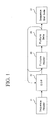
- an MPEG video decoder which comprises a picture decoding section 12 for starting a decoding of a MPEG bit-stream for predetermined pictures in response to a decoding start command 22 and outputting a decoding completion notification 23 upon completion of decoding the bit-stream for the foregoing predetermined pictures; a decoding frame buffer 13 for sequentially storing picture data decoded by the foregoing picture decoding section 12 and outputting a bufferfull notification 24 when a predetermined quantity of picture data is stored; a decoding start command generating section 14 for outputting the foregoing decoding start command 22 if the foregoing decoding completion notification 23 is outputted from the foregoing picture decoding section 12 and the foregoing bufferfull notification 24 is not outputted from the foregoing frame buffer 13; and a picture data output section 15 for transmitting the picture data stored in the foregoing decoding frame buffer 13 to a display unit 16.
- the decoding start command generating section 14 outputs the decoding start command 22.
- the picture decoding section 12 starts to decode the bit-stream for the predetermined pictures.
- the picture decoding section 12 outputs the decoding completion notification 23.
- the decoding start command generating section 14 outputs the decoding start command 22 to the picture decoding section 12. In such a manner described above, until a certain quantity of picture data is stored in the decoding frame buffer 13, the picture decoding section 12 decodes the picture data consecutively.
- the data rate greatly varies, so that the decoding of the data for one picture is not often completed within one frame time.
- a timing in starting the decoding of the bit-stream for one picture is made to be synchronous with a vertical synchronous signal V-Sync, and the decoding of the bit-stream for one picture is not completed within one frame time, an error concealment always occurs in a subsequent frame.
- the decoding of the bit-stream is consecutively performed.
- an input terminal 10 for receiving the MPEG bit-stream and a bit-stream buffer 11 for temporarily storing the bit-stream may be provided in the pre-stage of the picture decoding section 12.
- the decoding start command generating section 14 outputs a signal supplied from the outside, i.e. a host computer, the decoding completion notification 23 and the decoding start command 22 in response to the bufferfull notification 24.
- decoding starting conditions can be set from the outside.
- the decoding starting condition can be set so that the decoding is not started until the picture data (bit-stream) for a predetermined number of sheets is stored in the bit-stream buffer 11.
- the picture data output section 15 transmits the picture data stored in the decoding frame buffer 13 to the display unit 16 at a timing in synchronization with the vertical synchronous signal V-Sync 28. Upon receipt of the picture data, the display unit 16 displays an image.
- the picture data output section 15 consists of a display buffer 15c for temporarily storing the picture data to be transmitted to the display unit 16, and a display control section 15a for transferring the picture data from the decoding frame buffer 13 to the display buffer 15c. In this case, a pause (temporal stop) can be realized in a manner described below.
- the display control section 15a suspends to transfer the picture data from the decoding frame buffer 13 to the display buffer 15c.
- the picture decoding section 12 continues the decoding of the picture up to the point of time the bufferfull notification 24 is outputted from the decoding frame buffer 13. Then, with a storage of a certain quantity of the picture data in the decoding frame buffer 13, the frame bufferfull notification 24 is outputted from the decoding frame buffer 13, and then the decoding start command generating section 14 ceases to output the decoding start command 22. With no receipt of the decoding start command 22, the picture decoding section 12 suspends the decoding. Moreover, since picture data stored in the display buffer 15c is not updated, the same picture is displayed on the display unit 16.
- an MPEG video decoding method in which: respective MPEG bit-streams for the predetermined number of pictures are decoded, each of the decoded MPEG bit-stream is stored in the decoding frame buffer 13, and the picture data for one picture, which is stored in the foregoing decoding frame buffer 13, is sequentially transferred to the display unit 16.
- the decoding of the bit-stream is suspended, and when the storage quantity of the picture data becomes less than the foregoing certain quantity of the picture data, the decoding of the bit-stream is restarted.
- an MPEG video decoder which comprises a picture decoding section 112 for starting a decoding of a MPEG bit-stream in response to a decoding start command 122; a decoding frame buffer 113 for storing picture data decoded by the foregoing picture decoding section 112; a display control section 115 for analyzing parameters of the picture data for predetermined pictures, the picture data being decoded by the foregoing picture decoding section 112, and controlling a transfer of the foregoing picture data from the decoding frame buffer 113 to a display unit in response to an analysis result; and a decoding control section 114 for outputting the foregoing decoding start command 122 based on the parameters of the foregoing picture data.
- the display control section 115 analyzes the parameters of the picture data, and controls the transfer of the picture data from the decoding frame buffer 113 to the display unit in response to the analysis result. For example, the display control section 115 determines the number of display fields for each picture based on the parameter, and allows the display unit to display the picture for a period equivalent to the number of the display fields. The display control section 115 analyzes the parameter of a subsequent picture for this period, thereby determining the number of the display fields. Then, the display control section 115 permits the display unit to display the subsequent picture after the passage of the display time for one picture.
- the MPEG video decoder can easily cope with peculiar play backs such as the 3-2,pull down play back and the 1/2 slow play back.
- the number of the display fields at the time of the 3-2 pull down play back alone, the number of the display fields at the time of the 1/2 slow play back alone, and the number of the display fields at the time of both of the 3-2 pull down play back and the 1/2 slow play back are previously stored in the display control section 115 in a form described below.
- the proper number of the display fields can be easily determined by referring to the table.
- the display control section 115 there may be provided four registers of a re-order register 115a, a current register 115b, a field delay register 115c and a display register 115d. These four registers 115a to 115d manage picture data stored in the decoding frame buffer 113.
- another MPEG video decoder of the present invention should provide a status register 116 so that states of the registers 115a to 115d can be easily grasped. If it is recognized by referring to the state of the status register 116 that no data is stored in the re-order register 115a or the current register 115b, the decoding control section 114 outputs a decoding start command 112.
- a display field number calculation section 115f refers to the status register 116, and if it is recognized that the data has been stored in the display register 115d, the display field number calculation section 115f determines the number of display fields of the picture corresponding to the data stored in the display register 115d.
- Timings when the decoding control section 114 and the display control section 115 refers to the status register 116 can be set to that in synchronization with the vertical synchronous signal (V-Sync).
- Fig. 11 is a block diagram showing a MPEG video decoder of a first embodiment of the present invention.
- the MPEG video decoder of the first embodiment of the present invention consists of a bit-stream input terminal 10, a bit-stream buffer 11, a picture decoding section 12, a decoding frame buffer 13, a decoding start command generating section 14 and a picture data output section 15.
- a MPEG bit-stream is inputted to the bit-stream input terminal 10 from a storage media such as an ATM transmission path and a DVD.
- the bit-stream buffer 11 is a memory for temporarily storing the bit-stream.
- the picture decoding section 12 receives the bit-stream from the bit-stream buffer 11, and performs a variable length decoding processing, an inverse quantization processing, an inverse discrete cosine transform processing and a motion prediction processing, thus decoding the bit-stream.
- the picture decoding section 12 Upon receipt of a decoding start command 22 from the decoding start command generating section 14, the picture decoding section 12 starts to decode the bit-stream for one picture. Then, when the picture decoding section 12 completes the decoding of the bit-stream for one picture, the picture decoding section 12 outputs a decoding completion notification 23 to the decoding start command generating section 14.
- the picture decoding section 12 extracts a display time stamp (PTS) 26 from the bit-stream during decoding the bit-stream, and outputs the display time stamp PTS 26 to the picture data output section 15.
- PTS display time stamp
- the decoding frame buffer 13 stores a plurality of decoded pictures. As described above, the picture includes three kinds of an I picture, a P picture and a B picture.
- the picture decoding section 12 decodes the I picture without referring to other pictures.
- the picture decoding section 12 decodes the P picture
- the picture decoding section 12 refers to the picture in the past, i.e. the I picture or the P picture, which has been stored in the decoding frame buffer 13.
- the picture decoding section 12 refers to the pictures in the past and future, i.e. the I and P pictures, which have been stored in the decoding frame buffer 13.
- the decoding of the pictures is performed in the displaying order.
- the order for decoding the pictures differs from that for displaying the pictures, so that the pictures are rearranged in the display order of the pictures by the decoding frame buffer 13.
- the decoded picture must be stored in the decoding frame buffer 13 until the picture stored in the decoding frame buffer 13 is not referred to for the decoding of other pictures. Accordingly, the decoding frame buffer 13 has to possess a storage capacitance with a value that is large to some extent.
- the decoding frame buffer 13 shall possess a storage capacitance equivalent to three pictures and one or two pictures that were decoded prior to the P and B pictures shall be referred to when either the P picture or the B picture is decoded.
- the decoding frame buffer 13 stores the predetermined number of pictures, i.e. three pictures in this example, the decoding frame buffer 13 outputs the bufferfull notification 24.
- the decoding start command generating section 14 consists of a decoding control section 14a and a decoding switch 14b.
- the decoding control section 14a outputs a decoding starting permission 21 based on a bit-stream transfer notification 25 transmitted from the outside, i.e. a host computer, the decoding completion notification 23 outputted from the picture decoding section 12, and the bufferfull notification 24 outputted from the decoding frame buffer 13.
- the decoding control section 14a when the decoding control section 14a receives the bit-stream transfer notification 25 from the host computer, the decoding completion notification 23 is outputted from the picture decoding section 12 to the decoding control section 14a, and the bufferfull notification 24 is not outputted from the decoding frame buffer 13 to the decoding control section 14a, the decoding control section 14a outputs the decoding starting permission 21.
- the decoding switch 14b In response to the output of the decoding staring permission 21 from the decoding control section 14a, the decoding switch 14b outputs the decoding start command 22 to the picture decoding section 12.
- the host computer shall output the bit-stream transfer notification when the host computer transfers the bit-stream for one picture or more to the bit-stream buffer 11. Accordingly, after the bit-stream for one picture or more is stored in the bit-stream buffer 11, the picture decoding section 12 starts to decode a first picture.
- the picture data output section 15 consists of a display control section 15a, a display switch 15b and a display buffer 15c. If the display time stamp (PTS) 26 of the decoded picture is coincident with a self reference clock (STC), the display control section 15a outputs a transfer command 29 to the display switch 15b. Upon receipt of the transfer command 29, the display switch 15b transfer picture data from the decoding frame buffer 13 to the display buffer 15c. The picture data stored in the display buffer 15c is transmitted to the display unit 16 in synchronization with the vertical synchronous signal V-Sync 28 outputted from the display control section 15a. Thus, the image is displayed on the display unit 16.
- PTS display time stamp
- STC self reference clock
- the display unit 16 may adopt a NYSC (National Television System Committee) scheme or a PAL(Phase Alternation Line) scheme.
- picture decoding section 12, the decoding control section 14a and the display control section 15a may be realized in the form of hardware (semiconductor device) or software.
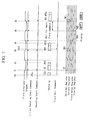
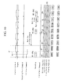
- Fig. 12 is a timing chart showing an operation of the MPEG video decoder of this embodiment.
- the input of the bit-stream to the bit-stream buffer 11 from the input terminal 10 is started at the time t0.
- the bit-stream transfer notification 25 is inputted from the host computer to the decoding control section 14a, so that the decoding control section 14a outputs the decoding starting permission 21.
- the decoding switch 14b Upon receipt of the decoding starting permission 21 from the decoding control section 14a, the decoding switch 14b outputs the decoding start command 22 to the picture decoding section 12.
- the picture decoding section 12 starts to decode the first picture data, i.e. picture 1, and the decoding frame buffer 13 stores the decoded picture data.
- the picture decoding section 12 When the decoding of the picture 1 is completed at the time t2, the picture decoding section 12 outputs the decoding completion notification 23 to the decoding control section 14a. Thereafter, the storage of the picture 1 into the decoding frame buffer 13 is completed slightly after the time t2. At this time, since only a storage area for one picture is used among the storage areas for three pictures stored in the decoding frame buffer 13, the bufferfull notification 24 is not outputted from the decoding frame buffer 13 to the decoding control section 14a. Therefore, upon receipt of the decoding completion notification 23 from the picture decoding section 12, the decoding control section 14a outputs the decoding starting permission 21 to the decoding switch 14b. Subsequently, the decoding switch 14b outputs the decoding start command 22 to the picture decoding section 12. Thus, the picture decoding section 12 starts to decode the second picture, i.e. picture 2.
- the picture decoding section 12 outputs the decoding completion notification 23 when the decoding of the picture 2 is completed.
- the decoding control section 14a outputs the decoding starting permission 21 to the decoding switch 14b, and outputs the decoding start command 22 to the picture decoding section 12.
- the picture decoding section 12 starts to decode a third picture data (picture 3).
- the display control section 15a outputs the transfer command 29 to the display switch 15b, and the decoding frame buffer 13 transfers the first picture data (picture 1) to the display buffer 15c. Then, the display buffer 15c transmits the picture 1 to the display unit 1 in synchronization with the vertical synchronous signal V-Sync 28. Thus, an image originating from the picture 1 is displayed on the display unit 16 for one frame period (two vertical synchronous period).
- the decoding completion notification 22 is outputted from the picture decoding section 12 to the decoding control section 14a.
- the decoding control section 14a outputs the decoding starting permission 21, and the decoding switch 14b outputs the decoding start command 22 to the picture decoding section 12, so that the picture decoding section 12 starts to decode a fourth picture data (picture 4).
- the decoding frame buffer 13 starts to store the picture 4 at the time t4, and outputs the bufferfull notification 24 to the decoding control section 14a.
- the picture decoding section 12 With completion of the decoding of the picture 4 at the time t5, the picture decoding section 12 outputs the decoding completion notification 23 to the decoding control section 14a. However, since the bufferfull notification 24 is outputted from the decoding frame buffer 13 to the decoding control section 14a, the decoding control section 14a does not output the decoding starting permission 21. Therefore, the picture decoding section 12 suspends the decoding of the picture data.
- the display control section 15a compares the self reference clock (SCR) with the display time (PTS) of the picture data stored in the decoding frame buffer 13. As a result of the comparison, since a time to output the picture 2 can be known, the display control section 15a outputs the transfer command 29 to the display switch 15b, and the picture 2 is transferred from the decoding frame buffer 13c to the display buffer 15c via the display switch 15b. Then, the picture 2 is transmitted from the display buffer 15c to the display unit 16 in synchronization with the vertical synchronous signal V-Sync 28. Thus, an image originating from the picture 2 is displayed on the display unit 16.
- SCR self reference clock
- PTS display time
- the picture 2 is transferred from the decoding frame buffer 13 to the display buffer 15c via the display switch 15b, a space is produced in the storage area of the decoding frame buffer 13.
- the output of the bufferfull notification 24 from the decoding frame buffer 13 is stopped.
- the decoding starting permission 21 is outputted from the decoding control section 14a to the decoding switch 14b, and then the decoding start command 22 is outputted from the decoding switch 14b to the picture decoding section 12.
- the picture decoding section 12 starts to decode a fifth picture data (picture 5).
- the decoding frame buffer 13 outputs the bufferfull notification 24 to the decoding control section 14a.
- the decoding completion notification 23 is outputted from the picture decoding section 12 to the decoding control section 14a after the completion of the decoding for the picture 5, the decoding control section 14a does not output the decoding starting permission 21. Accordingly, after the decoding of the picture 5 is completed, the picture decoding section 12 suspends the decoding processing.
- the display control section 15a allows the display switch 15b to be ON, so as to transfer the picture 3 from the decoding frame buffer 13 to the display buffer 15c. Then, the display control section 15a transfers the picture 3 from the display buffer 15c to the display unit 16 in synchronization with the vertical synchronous signal V-Sync 28. Thus, an image originating from the picture 3 is displayed on the display unit 16.
- the picture decoding section 12 starts to decode sixth picture data (picture 6).
- the MPEG video decoder of this embodiment starts the decoding of the picture data at the timings in response to both of the decoding completion notification 23 outputted from the picture decoding section 12 and the bufferfull notification 24 outputted from the decoding frame buffer 13.
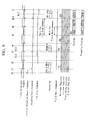
- Fig. 13 is a figure for comparing a likelihood of an error concealment in the MPEG video decoder of this embodiment with that of a previously-considered MPEG video decoder which starts the decoding of the picture data in synchronization with the vertical synchronous signal V-Sync.
- the hatched portions show frames in which the error concealment occurs.
- the conventional MPEG video decoder which start the decoding in synchronization with the vertical synchronous signal V-Sync, always causes the error concealment.
- the MPEG video decoder of this embodiment since, with an existence of a space in a storage area of the decoding frame buffer 13, the MPEG video decoder of this embodiment decodes the pictures consecutively, the error concealment may be avoided even when the decoding of the data for one picture is not completed within one frame time. In the example shown in Fig. 13 , the error concealment occurs only once.
- the timing for starting the decoding is not in synchronization with the vertical synchronous signal V-Sync 28. Specifically, if there is a space in the storage area of the decoding frame buffer 13, the decoding of the bit-stream is consecutively performed in the picture decoding section 12. Thus, even when one frame time or more is taken for decoding the data for one picture, the occurrence of the error concealment can be avoided, thus to reproduce the moving picture smoothly.
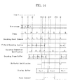
- Fig. 14 is a timing chart showing an operation of the MPEG video decoder of this embodiment at the time of a display pause (temporal stop of displaying).
- the pause command 27 (see Fig. 11 ) is outputted from the host computer to the display control section 15a from the time t5 to t7.5.
- the pictures 2 and 3 are stored in the decoding frame buffer 13.
- the picture decoding section 12 has just completed the decoding of the picture 4, and the picture 4 is being stored in the decoding frame buffer 13.
- the display control section 15a When the pause command 27 is inputted from the host computer to the display control section 15a, the display control section 15a does not turn on the display switch 15b, though the self reference clock (SCR) coincides with the display time stamp (PTS) of the picture stored in the decoding frame buffer 13. For this reason, the data of the display buffer 15c is not updated even at the time t6, and the display control section 15a transmits the picture 1 to the display unit 16 again in synchronization with the vertical synchronous signal V-Sync 28. Thus, the display unit 16 displays the picture originating from the picture 1 again. Moreover, since the decoding frame buffer 13 is in the situation where the buffer 13 stores three pictures, the decoding frame buffer 13 continues to output the bufferfull notification 24. Accordingly, the decoding starting permission 21 is not outputted from the decoding control section 14a, and the picture decoding section 12 suspends the decoding of a subsequent picture.
- SCR self reference clock
- PTS display time stamp
- the display control section 15a With stopping of the output of the pause command 27 at the time t7.5, the display control section 15a outputs the transfer command 29 to the display switch 15b, and the picture 2 is transferred from the decoding frame buffer 13 to the display buffer 15c. Then, the display control section 15a transmits the picture 2 to the display unit 16 in synchronization with the vertical synchronous signal V-Sync 28. Furthermore, since a space is produced in the storage area of the decoding buffer frame 13, the output of the bufferfull notification 24 is stopped. In response to the stop of the output of the bufferfull notification 24, the decoding control section 14a outputs the decoding starting permission 21 to the decoding switch 14b, and the decoding switch 14b outputs the decoding start command 22 to the picture decoding section 12. With the output of the decoding start command 22, the picture decoding section 12 starts to decode the picture 5. Thus, the display pause is realized.
- decoding is started at the time the bit-stream for one picture or more is transferred to the bit-stream buffer 11 in the above described embodiment, conditions for starting the decoding are not limited to this.
- the MPEG video decoder of this embodiment may be constructed such that instead of the bit-stream transfer notification 25 supplied from the host computer, a signal (bit-stream storage signal) is outputted from the bit-stream buffer 11 to the decoding control section 14a when a certain quantity of the bit-stream is stored in the bit-stream buffer 11.
- the decoding control section 14a outputs the decoding starting permission 21 in response to the bit-stream storage signal supplied from the bit-stream buffer 11, the decoding completion notification 23 supplied from the picture decoding section 12 and the bufferfull notification 23 supplied from the decoding frame buffer 13.
- Fig. 15 is a block diagram showing a MPEG video decoder of a second embodiment of the present invention.
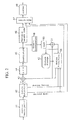
- the MPEG video decoder of this embodiment consists of a bit-stream input terminal 110, a bit-stream buffer 111, a picture decoding section 112, a decoding frame buffer 113, a decoding control section 114, a display control section 115 and a status register 116.
- the bit-stream buffer 111 stores a bit-stream supplied from the input terminal 110, and sequentially outputs the bit-stream for one picture to the picture decoding section 112. As soon as a decoding start command 122 is issued from the decoding control section 114, the picture decoding section 112 starts to decode the bit-stream sent from the bit-stream buffer 111. The picture decoded by the picture decoding section 112 is stored in the decoding frame buffer 113.
- the decoding frame buffer 113 has a storage area for, for example, three pictures.
- the storage area is divided into a plurality of banks, and one picture is stored in one bank.
- the decoding frame buffer 113 transmits the picture corresponding to the bank address included in the display starting command 127 to the display unit.
- the decoding control section 114 issues the decoding start command 122 to the picture decoding section 112 in synchronization with a vertical synchronous signal V-Sync outputted from a V-Sync generator (not shown).
- This decoding start command 122 is issued principally once for a period of two field, that is, once for a period of one frame.
- the decoding control section 114 issues an initial decoding start command 121 irrespective of the V-Sync.
- the display control section 115 includes a V-Sync counter 115e and a display field number calculation section 115f, in addition to four registers of a re-order register 115a, a current register 115b, a field delay register 115c, and a display register 115d.
- parameters are transferred to the display register 115d, as shown in Fig. 16 .
- a repeat first field flag is transferred to the display register 115d.
- a 1/2 slow play back command flag is transferred to the display register 115d as a parameter.
- the display control section 115 samples a slow play back command 129 from the outside using a decoding start command as a trigger, and if the slow play back command 129 is "1" , the display control section 115 transfers the slow play back command 129 as a slow play back flag to the display register 115d.
- the display field number calculation section 115f serves to control the number of display fields to be displayed. An operation of the display field number calculation section 115f is described later.
- the V-Sync counter 115e counts the number of V-Sync pulses equivalent to the number of display fields determined by the display field number calculation section 115f, and the display field number calculation section 115f uses the number of V-Sync pulses for controlling the number of display fields.
- the status register 116 monitors the states of the re-order register 115a, current register 115b, field delay register 115c and display register 115d, and expresses the states by a four bit signal. Specifically, if data such as a parameter and a bank address is stored in these registers 115a to 115d, a value of a bit corresponding to the register is set to "1", and if the data is not stored, the value of the bit corresponding to the register is set to "0" .
- the bits are arranged in the order of the re-order, current, field delay and display registers from MSB (Most Significant Bit).
- a value of the status register 116 is "1111”
- the value of the status register 116 is "0000" .
- Fig. 17 is a flow chart showing an operation of the decoding control section 114.
- step S11 a timing of a trailing edge of the V-Sync produced by the built-in V-Sync generator is detected. Then, the procedure proceeds to a step S12 in response to the trailing edge of the V-Sync, and it is decided whether or not a picture to be decoded is a B picture.
- the picture is not the B picture, that is, when the picture is either an I picture or a P picture
- the procedure proceeds to a step S13, and it is decided whether or not a bit 3 of the status register 13 is "1" .
- the procedure returns from the step S13 to the step S11.
- the bit 3 is "0" in the step S13, that is, when data is stored in the re-order register 115a
- the procedure proceeds to the step S15, so that the decoding start command is issued. Thereafter, the procedure returns to the step S11.
- a parameter of either the decoded I picture or the decoded P picture is stored in the re-order register 115a.
- the procedure proceeds to a step S14, and it is decided whether or not a bit 2 of the status register 116 is "1" .
- the procedure returns from the step S14 to the step S11.
- the bit 2 of the status register 116 is "0" in the step S14, that is, when data is not stored in the current register 115b, the procedure proceeds to the step S15, so as to issue the decoding start command. Thereafter, the procedure returns to the step S11.
- a parameter of the B picture decoded is stored in the current register 115b.
- Fig. 18 is a flow chart showing an operation of the display control section 115.
- step S21 a timing of a trailing edge of the V-Sync is detected.
- the procedure proceeds to the step S22 in response to the trailing edge of the V-Sync, and it is decided whether or not a bit 0 of the status register 116 is "1" .
- bit 0 Least Significant Bit: bit 0
- the procedure advance to the step S23, and the data stored in the display register 115d is analyzed. Then, the procedure proceeds to the step S24, and the number of display fields is determined in accordance with the repeat first field flag and the slow play back command flag. With the determination of the number of the display fields, the procedure proceeds to the step S25, and the display starting command 127 is issued.
- the procedure proceeds to the step S26, and the V-Sync counter 115e starts to count the V-Sync pulses.
- the procedure does not proceed until the V-Sync count value becomes equal to the number of the display fields, and when the V-Sync count value becomes equal to the number of the display fields, the procedure proceeds to the step S28, so that the display completion notification 128 is issued.
- Fig. 19 is a figure showing a method for counting the number of the display fields by the display control section 115.
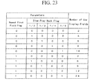
- a table (a look-up table) showing a relation among the repeat first field flag, the 1/2 slow play back command flag and the number of the display fields is stored in the display control section 115, as shown in Fig. 19 .
- the display field number calculation section 115f refers to the table and determines the number of the display fields from the states of the repeat first field flag and the 1/2 slow play back flag. For example, when any of the repeat first field flag and the 1/2 slow play back flag is "0" , the number of the display fields is set to two. When any of the repeat first field flag and the 1/2 slow play back flag is "1" , the number of the display fields is set to six.
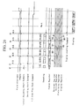
- Figs. 20 and 21 are timing charts showing an operation of the MPEG video decoder of this embodiment.
- the bit-stream is inputted in the order of the I picture I2, the B picture B0, the B picture B1, the P picture P5, the B picture B3, and the B picture B4,....
- the bit-stream is displayed in the order of the picture B0, the picture B1, the picture I2, the picture B3, the picture B4, and the picture P5,....
- the repeat first field command is added to the B pictures B0 and B4, and the I picture 12.
- the decoding control section 114 issues the initial decoding start command 122.
- the picture decoding section 112 decodes the picture header (I2) of the picture 12.
- the decoding control section 114 examines the register data 124a outputted from the status register 116 at the time t1. At this time, since the value of the status, register 116 is "0000" , the decoding control section 114 issues the decoding start command 122, so that the picture decoding section 112 starts to decode a coefficient of the picture I2. As soon as the decoding of the coefficient of the picture I2 is completed, the picture decoding section 112 subsequently decodes the picture header (B0) of the picture B0.
- the parameters and bank address of the picture I2 are stored in the re-order register 115a.
- the value of the status register 116 becomes "1000" (time t1.5).
- the decoding control section 114 examines the register data 124a outputted from the status register 116. At this time, since the value of the register data 124a is "1000" , the decoding control section 114 issues the decoding start command 112 at a timing in synchronization with the V-Sync. Thus, the picture decoding section 112 starts to decode a coefficient of the picture B0. At this time, the display control section 115 samples the 1/2 slow play back command 128 using the trailing edge of the decoding start command 122 as a trigger. Since the 1/2 slow play back command 128 is "1" , the 1/2 slow play back flag in the state of "1" is stored in the current register 115b. Furthermore, in this embodiment, since the repeat first field command is added to the picture B0, the repeat first field flag that is set to "1" is stored in the current register 115b.
- the decoding control section 114 examines the value of the bank status register 116 in response to the trailing edge of the V-Sync, and if there is a register having a value "0" , the decoding control section 114 issues the decoding start command 122. Upon the issue of the decoding start command 122 by the decoding control section 114, the picture decoding section 112 starts to decode the coefficient. Upon completion of the coefficient decoding, the picture decoding section 112 decodes the picture header of a subsequent picture.
- the picture B1 and the picture B5 are decoded.
- the value of the bank status register 116 becomes "1111" at the time t5. Accordingly, the decoding control section 114 stops the issue of the decoding start command 122. Thus, the picture decoding section 112 suspends the decoding.
- the display control section 115 analyzes the parameter of the display register 115d. As a result of the analysis of the parameters, since both of the repeat first field flag and the 1/2 slow play back flag are "1" , the display field number calculation section 115f set the number of the display fields to 6 (see Fig. 19 ). Then, the display control section 115 issues the display starting command 127 at the time t5.5. Thus, the picture B0 is transferred to the display unit, and displaying of the picture B0 is started.
- the display control section 115 displays the pictures for 6 fields, so that the display control section 115 counts the V-Sync five times, and when a time of a period of six fields has passed, the display control section 115 issues the display completion notification 128 to the status register 116. Then, the display control section 115 shifts the contents of the current register 115b and the field delay register 115c to the field delay register 115c and the display register 115d, respectively. Thus, a space is produced in the current register 115b, so that the value of the status register 116 becomes "1011" (time t5.9).
- the decoding control section 114 examines the value of the status register 116 at the time t6. Since the value of the status register 116 is "1011", the decoding control section 114 issues the decoding start command. Thus, the picture decoding section 112 starts to decode a coefficient of the picture B3. A parameter of the picture B3 is stored in the current register 115b. As a result, the value of the status register 116 becomes "1111" .
- the display control section 115 examines the parameter of the picture B1 which has been transferred to the display register 115d. Since the repeat first field flag is "0" and the 1/2 slow play back command flag is "1" , the number of the display fields is set to four. Then, the display control section 115 issues the display starting command 127, and the display unit starts to display the picture B1 (time t6.5). Upon completion of the period for displaying the picture B1, the display control section 115 issues the display completion notification 128, and shifts the data of the current register 115b and the field delay register 115c to the field delay register 115c and the display register 115d, respectively.
- the MPEG video decoder of this embodiment correctly executes the 3-2 pull down and the 1/2 slow play back.
- the display control section 115 determines the number of the display fields by using the table as shown in Fig. 19 , in the MPEG video decoder of this embodiment. Therefore, the MPEG video decoder of this embodiment can cope with the 3-2 pull down play back, the 1/2 slow play back, and the 3-3 pull down play back and 1/2 slow play back.
- the PTS (Presentation Time Stamp) is superposed on the pictures of the MPEG.
- the PTS is data indicating a time for displaying each of the pictures.
- the MPEG video decoder performs a time control of the play back using the PTS and a STC (System Time Clock) built therein.
- Fig. 22 is a figure showing a change with the passage of time of a STC at the time of an ordinary play back and a peculiar play back (3-2 pull down and 1/2 slow play back).
- the abscissa indicates a time and the ordinate indicates the STC.
- the STC monotonously increases with the passage of time.
- the slope of an increment of the STC at the time of the ordinary play back normal play
- the slope at the time of the 3-2 pull down play back must be 2/3
- the slope at the time of the 1/2 slow play back must be 1/2
- the slope at the time 3-2 pull down and 1/2 slow play back must be 1/3.
- the decoding of the picture is performed in synchronization with the V-Sync in the above described embodiment, it is satisfactory that the decoding of the picture is performed without synchronizing the decoding of the picture with the V-Sync as in the first embodiment.
- An MPEG video decoder may comprise:
- said picture data output section (15) may transmit said picture data to said display unit (16) in synchronisation with a vertical synchronous signal (28).
- said picture decoding section (12) may refer to the picture data stored in said decoding frame buffer (13), thereby decoding other picture data.
- said MPEG bit-stream may be inputted from either an ATM (Asynchronous Transfer Mode) transmission path or a storage medium to said picture decoding section (12) via a bit-stream buffer (11).
- ATM Asynchronous Transfer Mode
- said picture data output section (15) may include a display buffer (15c) for temporarily storing the picture data to be outputted to said display unit (16), and a display control section (15a) for transferring the picture data from said decoding frame buffer (13) to said display buffer (15c).
- said display control section (15a) suspends to transfer the picture data from said decoding frame buffer (13) to said display buffer (15c) when a pause command (27) is inputted thereto.
- the MPEG video decoder may further comprise:
- said decoding start command generating section (14) may output said decoding start command (22) in response to a command from an outside apparatus, said decoding completion notification (23), and said bufferfull notification (24).
- An MPEG video decoding method may comprise the steps of:
- said picture may be transferred to said display unit (16) at a timing in synchronisation with a vertical synchronous signal (28).
Landscapes
- Engineering & Computer Science (AREA)
- Multimedia (AREA)
- Signal Processing (AREA)
- Computing Systems (AREA)
- Theoretical Computer Science (AREA)
- Compression Or Coding Systems Of Tv Signals (AREA)
Applications Claiming Priority (3)
| Application Number | Priority Date | Filing Date | Title |
|---|---|---|---|
| JP35089398 | 1998-12-10 | ||
| JP7653099A JP2000232649A (ja) | 1998-12-10 | 1999-03-19 | Mpegビデオ復号器及びmpegビデオ復号方法 |
| EP19990306439 EP1011270A3 (fr) | 1998-12-10 | 1999-08-16 | Décodeur MPEG |
Related Parent Applications (1)
| Application Number | Title | Priority Date | Filing Date |
|---|---|---|---|
| EP19990306439 Division EP1011270A3 (fr) | 1998-12-10 | 1999-08-16 | Décodeur MPEG |
Publications (2)
| Publication Number | Publication Date |
|---|---|
| EP1968327A2 true EP1968327A2 (fr) | 2008-09-10 |
| EP1968327A3 EP1968327A3 (fr) | 2014-02-26 |
Family
ID=26417675
Family Applications (2)
| Application Number | Title | Priority Date | Filing Date |
|---|---|---|---|
| EP20080157947 Withdrawn EP1968327A3 (fr) | 1998-12-10 | 1999-08-16 | Décodeur vidéo MPEG et procédé de décodage vidéo MPEG |
| EP19990306439 Withdrawn EP1011270A3 (fr) | 1998-12-10 | 1999-08-16 | Décodeur MPEG |
Family Applications After (1)
| Application Number | Title | Priority Date | Filing Date |
|---|---|---|---|
| EP19990306439 Withdrawn EP1011270A3 (fr) | 1998-12-10 | 1999-08-16 | Décodeur MPEG |
Country Status (3)
| Country | Link |
|---|---|
| US (2) | US6628719B1 (fr) |
| EP (2) | EP1968327A3 (fr) |
| JP (1) | JP2000232649A (fr) |
Families Citing this family (41)
| Publication number | Priority date | Publication date | Assignee | Title |
|---|---|---|---|---|
| EP1085767B1 (fr) * | 1999-09-20 | 2011-08-10 | Panasonic Corporation | Dispositif de codage/d'enregistrement, interrompant le codage des données vidéo et l'échantillonnage d'un signal audio à la réponse d'une instruction de pause d'enregistrement, pour permettre la reproduction ininterrompue des données enregistrées avant et après la pause d'enregistrement |
| JP4526145B2 (ja) | 1999-12-28 | 2010-08-18 | 富士通セミコンダクター株式会社 | Mpegビデオ復号器およびmpegビデオ復号方法 |
| JP2001339700A (ja) * | 2000-05-26 | 2001-12-07 | Nec Corp | 電子透かし処理装置並びに電子透かし挿入方法および電子透かし検出方法 |
| JP3674495B2 (ja) * | 2000-10-26 | 2005-07-20 | セイコーエプソン株式会社 | 表示ドライバ、これを備えた表示ユニット及び電子機器 |
| JP3917363B2 (ja) * | 2000-12-12 | 2007-05-23 | 株式会社東芝 | 画像復号化装置及び画像復号化方法 |
| US8284844B2 (en) | 2002-04-01 | 2012-10-09 | Broadcom Corporation | Video decoding system supporting multiple standards |
| US6963613B2 (en) * | 2002-04-01 | 2005-11-08 | Broadcom Corporation | Method of communicating between modules in a decoding system |
| ATE443972T1 (de) | 2002-07-11 | 2009-10-15 | Panasonic Corp | Virtuellen multi-hypothesen b-bild anzeigepuffer mittels stehlen von platz aus dem h.264 postdekoderpuffer. |
| FR2842979B1 (fr) * | 2002-07-24 | 2004-10-08 | Thomson Licensing Sa | Procede et dispositif de traitement de donnees numeriques |
| TWI249356B (en) * | 2002-11-06 | 2006-02-11 | Nokia Corp | Picture buffering for prediction references and display |
| MY135449A (en) * | 2003-02-18 | 2008-04-30 | Nokia Corp | Picture coding method |
| JP2006518127A (ja) * | 2003-02-18 | 2006-08-03 | ノキア コーポレイション | ピクチャ復号化方法 |
| US20040258160A1 (en) * | 2003-06-20 | 2004-12-23 | Sandeep Bhatia | System, method, and apparatus for decoupling video decoder and display engine |
| US8077778B2 (en) * | 2003-10-31 | 2011-12-13 | Broadcom Corporation | Video display and decode utilizing off-chip processor and DRAM |
| US20050201471A1 (en) * | 2004-02-13 | 2005-09-15 | Nokia Corporation | Picture decoding method |
| US7296205B2 (en) * | 2004-02-18 | 2007-11-13 | Nokia Corporation | Data repair |
| US9124907B2 (en) * | 2004-10-04 | 2015-09-01 | Nokia Technologies Oy | Picture buffering method |
| CN100579223C (zh) * | 2004-12-02 | 2010-01-06 | 索尼株式会社 | 编码装置和方法 |
| US7885338B1 (en) * | 2005-04-25 | 2011-02-08 | Apple Inc. | Decoding interdependent frames of a video for display |
| CN101502096B (zh) * | 2006-08-10 | 2013-06-26 | 佳能株式会社 | 图像解码设备 |
| JP4799504B2 (ja) * | 2006-08-10 | 2011-10-26 | キヤノン株式会社 | 画像復号化装置及びその制御方法 |
| KR100813436B1 (ko) | 2006-12-21 | 2008-03-13 | 주식회사 휴맥스 | 영상 재생 장치 및 영상 재생 방법 |
| JP4889573B2 (ja) | 2007-06-07 | 2012-03-07 | ヤマハ株式会社 | 画像処理装置 |
| JP4410277B2 (ja) * | 2007-08-28 | 2010-02-03 | 富士通株式会社 | 半導体装置、および半導体装置の制御方法 |
| US20100046629A1 (en) * | 2008-08-19 | 2010-02-25 | Chun-Chia Chen | Video decoding system and method thereof |
| US20100254453A1 (en) * | 2009-04-02 | 2010-10-07 | Qualcomm Incorporated | Inverse telecine techniques |
| JP2012208342A (ja) * | 2011-03-30 | 2012-10-25 | Sony Corp | 信号処理回路と信号処理方法および表示装置 |
| JP5772623B2 (ja) * | 2012-01-20 | 2015-09-02 | 富士通株式会社 | 動画像符号化装置、動画像符号化方法及び動画像符号化プログラム |
| US9568985B2 (en) * | 2012-11-23 | 2017-02-14 | Mediatek Inc. | Data processing apparatus with adaptive compression algorithm selection based on visibility of compression artifacts for data communication over camera interface and related data processing method |
| TW201740739A (zh) * | 2016-05-05 | 2017-11-16 | 晨星半導體股份有限公司 | 多媒體裝置的控制電路及其資料處理方法 |
| JP7289551B2 (ja) * | 2021-05-19 | 2023-06-12 | 株式会社ユニバーサルエンターテインメント | 遊技機 |
| JP7289553B2 (ja) * | 2021-05-19 | 2023-06-12 | 株式会社ユニバーサルエンターテインメント | 遊技機 |
| JP7289548B2 (ja) * | 2021-05-19 | 2023-06-12 | 株式会社ユニバーサルエンターテインメント | 遊技機 |
| JP7289545B2 (ja) * | 2021-05-19 | 2023-06-12 | 株式会社ユニバーサルエンターテインメント | 遊技機 |
| JP7289552B2 (ja) * | 2021-05-19 | 2023-06-12 | 株式会社ユニバーサルエンターテインメント | 遊技機 |
| JP7289549B2 (ja) * | 2021-05-19 | 2023-06-12 | 株式会社ユニバーサルエンターテインメント | 遊技機 |
| JP7289554B2 (ja) * | 2021-05-19 | 2023-06-12 | 株式会社ユニバーサルエンターテインメント | 遊技機 |
| JP7289546B2 (ja) * | 2021-05-19 | 2023-06-12 | 株式会社ユニバーサルエンターテインメント | 遊技機 |
| JP7043659B2 (ja) * | 2021-05-19 | 2022-03-29 | 株式会社ユニバーサルエンターテインメント | 遊技機 |
| JP7289550B2 (ja) * | 2021-05-19 | 2023-06-12 | 株式会社ユニバーサルエンターテインメント | 遊技機 |
| JP7289547B2 (ja) * | 2021-05-19 | 2023-06-12 | 株式会社ユニバーサルエンターテインメント | 遊技機 |
Citations (2)
| Publication number | Priority date | Publication date | Assignee | Title |
|---|---|---|---|---|
| EP0294959A2 (fr) * | 1987-06-09 | 1988-12-14 | Sony Corporation | Convertisseurs de standard de télévision |
| EP0701368A2 (fr) * | 1994-08-23 | 1996-03-13 | Discovision Associates | Conversion de débit de données |
Family Cites Families (20)
| Publication number | Priority date | Publication date | Assignee | Title |
|---|---|---|---|---|
| US5038209A (en) * | 1990-09-27 | 1991-08-06 | At&T Bell Laboratories | Adaptive buffer/quantizer control for transform video coders |
| JP2802694B2 (ja) | 1991-10-30 | 1998-09-24 | 富士写真フイルム株式会社 | 画像再生装置および方法 |
| JP3240017B2 (ja) * | 1993-01-11 | 2001-12-17 | ソニー株式会社 | Mpeg信号記録方法およびmpeg信号再生方法 |
| JP3427416B2 (ja) * | 1993-05-25 | 2003-07-14 | ソニー株式会社 | 多重化データ分離装置および方法 |
| JP2829246B2 (ja) | 1994-09-28 | 1998-11-25 | 株式会社メガチップス | 画像伸張装置 |
| JP3017644B2 (ja) | 1994-10-25 | 2000-03-13 | 株式会社グラフィックス・コミュニケーション・ラボラトリーズ | 画像復号装置における表示用同期信号発生装置 |
| JPH08149474A (ja) * | 1994-11-17 | 1996-06-07 | Hitachi Ltd | 動画像復号化装置 |
| JP3824678B2 (ja) * | 1995-05-09 | 2006-09-20 | 株式会社ルネサステクノロジ | 画像復号表示装置 |
| JP3301274B2 (ja) * | 1995-06-20 | 2002-07-15 | 株式会社日立製作所 | 符号化映像データの復号装置 |
| MY115648A (en) * | 1995-08-23 | 2003-08-30 | Sony Corp | Encoding/decoding fields of predetermined field polarity apparatus and method |
| JPH0993577A (ja) | 1995-09-28 | 1997-04-04 | Toshiba Corp | 動画像デコード装置 |
| EP0878097B1 (fr) * | 1996-01-08 | 2003-03-26 | International Business Machines Corporation | Serveur de fichiers pour distribution de fichiers multimedias |
| US5668599A (en) * | 1996-03-19 | 1997-09-16 | International Business Machines Corporation | Memory management for an MPEG2 compliant decoder |
| JP2848326B2 (ja) * | 1996-03-28 | 1999-01-20 | 日本電気株式会社 | Mpeg符号化画像復号装置 |
| JPH1023375A (ja) * | 1996-07-04 | 1998-01-23 | Matsushita Electric Ind Co Ltd | 順次ディジタルビデオ復号化装置 |
| KR100198541B1 (ko) | 1996-08-26 | 1999-06-15 | 구자홍 | 영상 프레임 데이터를 일 메모리에 저장하는 방법 |
| JPH1093917A (ja) | 1996-09-11 | 1998-04-10 | Fujitsu Ltd | 画像処理装置 |
| US6128340A (en) * | 1997-03-14 | 2000-10-03 | Sony Corporation | Decoder system with 2.53 frame display buffer |
| US6263023B1 (en) * | 1998-10-15 | 2001-07-17 | International Business Machines Corporation | High definition television decoder |
| US6654539B1 (en) * | 1998-10-26 | 2003-11-25 | Sony Corporation | Trick playback of digital video data |
-
1999
- 1999-03-19 JP JP7653099A patent/JP2000232649A/ja active Pending
- 1999-08-11 US US09/372,039 patent/US6628719B1/en not_active Expired - Lifetime
- 1999-08-16 EP EP20080157947 patent/EP1968327A3/fr not_active Withdrawn
- 1999-08-16 EP EP19990306439 patent/EP1011270A3/fr not_active Withdrawn
-
2003
- 2003-07-08 US US10/614,054 patent/US7555045B2/en not_active Expired - Fee Related
Patent Citations (2)
| Publication number | Priority date | Publication date | Assignee | Title |
|---|---|---|---|---|
| EP0294959A2 (fr) * | 1987-06-09 | 1988-12-14 | Sony Corporation | Convertisseurs de standard de télévision |
| EP0701368A2 (fr) * | 1994-08-23 | 1996-03-13 | Discovision Associates | Conversion de débit de données |
Also Published As
| Publication number | Publication date |
|---|---|
| US6628719B1 (en) | 2003-09-30 |
| EP1011270A2 (fr) | 2000-06-21 |
| JP2000232649A (ja) | 2000-08-22 |
| US20040008788A1 (en) | 2004-01-15 |
| EP1968327A3 (fr) | 2014-02-26 |
| US7555045B2 (en) | 2009-06-30 |
| EP1011270A3 (fr) | 2006-03-01 |
Similar Documents
| Publication | Publication Date | Title |
|---|---|---|
| US6628719B1 (en) | MPEG video decoder and MPEG video decoding method | |
| US5949948A (en) | Method and apparatus for implementing playback features for compressed video data | |
| US5699117A (en) | Moving picture decoding circuit | |
| EP0843485B1 (fr) | Décodeur vidéo avec une mémoire unifiée | |
| US6996174B2 (en) | MPEG video decoder with integrated scaling and display functions | |
| US5990958A (en) | Apparatus and method for MPEG video decompression | |
| US6320909B1 (en) | Picture decoding and display unit including a memory having reduce storage capacity for storing pixel data | |
| WO2000059219A1 (fr) | Procede et dispositif de decodage video numerique, de tampon et de conversion de frequence de trames | |
| JPH10511526A (ja) | 圧縮されたビデオデータを復号化し、表示するメモリコントローラ | |
| US5926223A (en) | Adaptive video decompression | |
| KR100269869B1 (ko) | 데이타율 변환 방법 및 장치 | |
| US5903311A (en) | Run level pair buffering for fast variable length decoder circuit | |
| US8009741B2 (en) | Command packet system and method supporting improved trick mode performance in video decoding systems | |
| US7333714B2 (en) | Method and system for performing reverse play of SD MPEG video | |
| JP4769268B2 (ja) | Mpegビデオ復号器及びmpegビデオ復号方法 | |
| KR100249235B1 (ko) | 에이치디티브이 비디오 디코더 | |
| WO2001050220A2 (fr) | Procedes et appareil de lecture de dvd en marche arriere | |
| JPH08116532A (ja) | 画像復号化方式および装置 | |
| KR100469258B1 (ko) | 썸네일 영상 생성 장치 및 방법 | |
| US6459736B1 (en) | Moving picture decoding apparatus and method | |
| JPH099258A (ja) | 符号化映像データの復号装置 | |
| JPH08149464A (ja) | フレームレート変換機能付き画像復号装置 | |
| JP2885219B2 (ja) | 動画像復号化方法及び装置 | |
| KR19990058626A (ko) | 엠펙 디코더 | |
| WO1998054908A1 (fr) | Decodage a deux passages d'images b mpeg pour reduction de memorisation |
Legal Events
| Date | Code | Title | Description |
|---|---|---|---|
| PUAI | Public reference made under article 153(3) epc to a published international application that has entered the european phase |
Free format text: ORIGINAL CODE: 0009012 |
|
| AC | Divisional application: reference to earlier application |
Ref document number: 1011270 Country of ref document: EP Kind code of ref document: P |
|
| AK | Designated contracting states |
Kind code of ref document: A2 Designated state(s): DE FR GB |
|
| RAP1 | Party data changed (applicant data changed or rights of an application transferred) |
Owner name: FUJITSU MICROELECTRONICS LIMITED |
|
| RAP1 | Party data changed (applicant data changed or rights of an application transferred) |
Owner name: FUJITSU SEMICONDUCTOR LIMITED |
|
| PUAL | Search report despatched |
Free format text: ORIGINAL CODE: 0009013 |
|
| AK | Designated contracting states |
Kind code of ref document: A3 Designated state(s): DE FR GB |
|
| RIC1 | Information provided on ipc code assigned before grant |
Ipc: H04N 7/50 00000000AFI20140117BHEP |
|
| 17P | Request for examination filed |
Effective date: 20140724 |
|
| RBV | Designated contracting states (corrected) |
Designated state(s): DE FR GB |
|
| AKX | Designation fees paid |
Designated state(s): DE |
|
| 17Q | First examination report despatched |
Effective date: 20141021 |
|
| RAP1 | Party data changed (applicant data changed or rights of an application transferred) |
Owner name: SOCIONEXT INC. |
|
| STAA | Information on the status of an ep patent application or granted ep patent |
Free format text: STATUS: THE APPLICATION HAS BEEN WITHDRAWN |
|
| 18W | Application withdrawn |
Effective date: 20170622 |