EP1968011A2 - Procédé et appareil pour l'étalonnage d'une caméra et véhicule - Google Patents
Procédé et appareil pour l'étalonnage d'une caméra et véhicule Download PDFInfo
- Publication number
- EP1968011A2 EP1968011A2 EP08001730A EP08001730A EP1968011A2 EP 1968011 A2 EP1968011 A2 EP 1968011A2 EP 08001730 A EP08001730 A EP 08001730A EP 08001730 A EP08001730 A EP 08001730A EP 1968011 A2 EP1968011 A2 EP 1968011A2
- Authority
- EP
- European Patent Office
- Prior art keywords
- calibration
- camera
- cameras
- shot
- bird
- Prior art date
- Legal status (The legal status is an assumption and is not a legal conclusion. Google has not performed a legal analysis and makes no representation as to the accuracy of the status listed.)
- Withdrawn
Links
Images


Classifications
-
- H—ELECTRICITY
- H04—ELECTRIC COMMUNICATION TECHNIQUE
- H04N—PICTORIAL COMMUNICATION, e.g. TELEVISION
- H04N17/00—Diagnosis, testing or measuring for television systems or their details
- H04N17/002—Diagnosis, testing or measuring for television systems or their details for television cameras
-
- G—PHYSICS
- G06—COMPUTING; CALCULATING OR COUNTING
- G06T—IMAGE DATA PROCESSING OR GENERATION, IN GENERAL
- G06T7/00—Image analysis
- G06T7/80—Analysis of captured images to determine intrinsic or extrinsic camera parameters, i.e. camera calibration
Definitions
- the present invention relates to a camera calibration apparatus and a camera calibration method for realizing calibration processing needed to project camera-shot images onto a predetermined surface and merge them together.
- the invention also relates to a vehicle employing such an apparatus and a method.
- a shot image is subjected to coordinate conversion to generate and present a bird's-eye view image as if viewed from above the ground. Presented with such a bird's-eye view image, the driver of a vehicle can more easily grasp the circumstances around the vehicle.
- Fig. 25 is a plan view of a vehicle equipped with such a field-of-view assistance system
- Fig. 26 is a diagram showing the vehicle as seen obliquely from the left front.
- the vehicle is fitted with, at its front, back, left side, and right side respectively, a camera 1F as a front camera, a camera 1B as a back camera, a camera 1L as a left-hand camera, and a camera 1R as a right-hand camera.
- the shooting areas of the cameras 1F and 1L are indicated individually as hatched areas.
- Fig. 27 is a diagram schematically showing the thus displayed all-around bird's-eye view image 900.
- the all-around bird's-eye view image 900 at the front, back, left side, and right side of the vehicle are shown bird's-eye view images based on the images shot with the cameras I F, 1B, 1L, and 1R respectively.
- An image shot with a camera can be projected onto the ground either by a method based on perspective projection conversion or by a method based on planar projection conversion.
- Fig. 28 is a diagram showing the concept of perspective projection conversion.
- the coordinates (x, y) of a point on a shot image are converted to the coordinates (X, Y) of a point on a bird's-eye view image. Since the bird's-eye view image is an image on the ground, at any point on it, the coordinate (Z) in the height direction is zero.
- planar projection conversion a calibration pattern is arranged in a shooting area and, based on the calibration pattern shot, calibration operation is performed that involves finding a conversion matrix that represents the correspondence between coordinates in a shot image (two-dimensional camera coordinates) and coordinates in a bird's-eye view image (two-dimensional world coordinates).
- This conversion matrix is generally called a homography matrix.
- Fig. 29 is a diagram showing the concept of planar projection conversion.
- planar projection conversion the coordinates (x, y) of a point on the shot image are converted to the coordinates (x', y') of a point on the bird's-eye view image.
- Planar projection conversion does not require camera external or internal information, and permits coordinates mutually corresponding between the shot image and the bird's-eye view image to be specified based on the calibration pattern actually shot. This helps eliminate (or reduce) the effect of errors in camera installation.
- a homography matrix for projecting an image shot with a given camera onto the ground can be calculated based on four or more characteristic points with previously known coordinates.
- To project images shot with a plurality of cameras into a common merged image it is necessary to set the characteristic points used by the different cameras on a common two-dimensional coordinate system. That is, it is necessary to define a two-dimensional coordinate system common to all the cameras as shown in Fig. 30 and specify on this two-dimensional coordinate system the coordinates of four or more characteristic points for each camera.
- a lattice-shaped calibration pattern that covers the shooting areas of all the cameras is arranged around a vehicle, and the intersections in the lattice are used as characteristic points.
- a calibration pattern like this has, for example, a size twice the longitudinal and lateral dimensions of a vehicle, and thus it not only occupies a large area in calibration operation but also makes it troublesome to set up an environment for calibration, increasing the burden imposed by calibration operation as a whole. For more efficient calibration operation, a simpler calibration method has been sought.
- JP-A-2004-342067 discloses a method in which conversion parameters based on planar projection conversion are adjusted by use of images shot at a plurality of positions (see, among others, paragraph 69 etc.). Even this method requires that a coordinate system (two-dimensional world coordinate system) common to the plurality of images be set, and thus provides no solution to the trouble with setting up the calibration environment.
- a camera calibration apparatus is provided with: a parameter deriver adapted to find parameters for projecting images shot with N cameras (where N is an integer of 3 or more) onto a predetermined surface and merging the images together.
- the N cameras include a first camera, a second camera, ... and an N-the camera.
- the i-th camera (where i is every integer between 1 and N, inclusive) shares a common shooting area with at least one of the other (N - 1) cameras, so that there are a plurality of such common shooting areas in total.
- the parameter deriver finds the parameters based on the results of the shooting of calibration patterns arranged in the common shooting areas with the corresponding cameras.
- the calibration patterns are arranged separate from one another.
- the common shooting areas at least include a common shooting area shared between the first and second cameras, a common shooting area shared between the second and third cameras, ... and a common shooting area shared between the (N - 1)-th and N-th cameras.
- the parameter deriver defines as a global coordinate system the coordinate system onto which the shot images are projected to be merged together.
- the parameter deriver is provided with: a first parameter deriver adapted to find, by use of the results of the shooting of the calibration patterns with the first to (N - 1)-th cameras, a first parameter for subjecting the images shot with the first to (N - 1)-th cameras to coordinate conversion onto the global coordinate system; and a second parameter deriver adapted to find, based on coordinate information on the currently targeted calibration pattern obtained by subjecting the currently targeted calibration pattern shot with the (N - 1)-th camera to coordinate conversion onto the global coordinate system by use of the first parameter and based on coordinate information on the currently targeted calibration pattern shot with the N-th camera, a second parameter for subjecting the image shot with the N-th camera to coordinate conversion onto the global coordinate system.
- the parameter deriver thus finds the parameters
- the parameter deriver defines as a global coordinate system the coordinate system onto which the shot images are projected to be merged together.
- the parameter deriver previously knows the shapes of the individual calibration patterns, and previously recognizes those shapes as "previously known information".
- the parameter deriver first tentatively finds the parameters by use of the results of the shooting of the calibration patterns with the individual cameras and then, by use of the tentatively found parameters, subjects the calibration patterns shot with the individual cameras to coordinate conversion onto the global coordinate system to adjust the tentatively found parameters based on the shapes of the calibration patterns after the coordinate conversion and based on the previously known information. Through this adjustment, the parameter deriver finds the parameters definitively.
- a vehicle is provided with N cameras and an image processing apparatus.
- the image processing apparatus is provided with any of the camera calibration apparatuses described above.
- a camera calibration method finds parameters for projecting images shot with N cameras (where N is an integer of 3 or more) onto a predetermined surface and merging the images together.
- the N cameras include a first camera, a second camera, ... and an N-th camera.
- the i-th camera shares a common shooting area with at least one of the other (N - 1) cameras, so that there are a plurality of such common shooting areas in total.
- the camera calibration method involves finding the parameters based on the results of the shooting of calibration patterns arranged in the common shooting areas with the corresponding cameras. Furthermore, the calibration patterns are arranged separate from one another.
- Fig. 1 is a plan view of a vehicle 100 equipped with a field-of-view assistance system according to an embodiment of the invention, and shows how the vehicle 100 is fitted with cameras.
- Fig. 2 is a diagram showing the vehicle 100 as seen obliquely from the left front.
- Figs. 1 and 2 show a truck as the vehicle 100, the vehicle 100 may be any type of vehicle (such as a common passenger car) other than a truck.
- the vehicle 100 is located on the ground (for example, on the surface of a road). In the following description, it is assumed that the ground lies on the horizontal plane, and that the word "height" denotes a height with respect to the ground.
- the vehicle 100 is fitted with cameras (image-sensing apparatuses) 1F, 1R, 1L, and 1B at its front, right side, left side, and back, respectively.
- cameras image-sensing apparatuses
- the relevant one or more or each of them is often referred to simply as "the camera” or “the cameras” or “each camera”.
- the camera 1F is installed, for example, above a front mirror of the vehicle 100, and the camera 1L is installed, for example, at the topmost part of the left side of the vehicle 100.
- the camera 1B is installed, for example, at the topmost part of the back of the vehicle 100, and the camera 1R is installed, for example, at the topmost part of the right side of the vehicle 100.
- the cameras 1F, 1R, 1L, and 1B are fitted to the vehicle 100 in such a way that the optical axis of the camera 1F points obliquely frontward-downward with respect to the vehicle 100, that the optical axis of the camera 1B points obliquely backward-downward with respect to the vehicle 100, that the optical axis of the camera 1L points obliquely leftward-downward with respect to the vehicle 100, and that the optical axis of the camera 1R points obliquely rightward-downward with respect to the vehicle 100.
- Fig. 2 shows the fields of view - that is, shooting areas - of the cameras.
- the shooting areas of the cameras 1F, 1R, 1L, and 1B are indicated by 2F, 2R, 2L, and 2B respectively.
- For the shooting areas 2R and 2B, only parts of them are shown in Fig. 2 .
- Figs. 3A to 3D show the shooting areas 2F, 2L, 2B, and 2R as seen from above, that is, the shooting areas 2F, 2L, 2B, and 2R on the ground.
- Fig. 4 collectively shows the shooting areas shown in Figs. 3A to 3D (what the hatching there indicates will be described later).
- the camera 1F shoots a subject (including the surface of the road) located within a predetermined area in front of the vehicle 100.
- the camera 1R shoots a subject located within a predetermined area on the right of the vehicle 100.
- the camera 1L shoots a subject located within a predetermined area on the left of the vehicle 100.
- the camera 1 B shoots a subject located within a predetermined area behind the vehicle 100.
- the cameras 1F and 1L both shoot in a predetermined area situated obliquely at the left front of the vehicle 100. That is, in this predetermined area situated obliquely at the left front of the vehicle 100, the shooting areas 2F and 2L overlap.
- An area in which the shooting areas of two cameras overlap is called a common shooting area (common shooting space).
- the area in which the shooting areas of the cameras 1F and 1L overlap is indicated by 3 FL .
- such common shooting areas are represented by hatched areas.
- the shooting areas 2F and 2R overlap in a predetermined area situated obliquely at the right front of the vehicle 100, forming a common shooting area 3 FR ; the shooting areas 2B and 2L overlap in a predetermined area situated obliquely at the left back of the vehicle 100, forming a common shooting area 3 BL ; and the shooting areas 2B and 2R overlap in a predetermined area situated obliquely at the right back of the vehicle 100, forming a common shooting area 3 BR .
- Fig. 5 is a block diagram showing the configuration of a field-of-view assistance system according to an embodiment of the invention.
- the cameras 1F, 1R, 1L, and 1B shoot, and feed the signals representing the images obtained as the result (henceforth also referred to as the "shot images") to an image processing apparatus 10.
- the image processing apparatus 10 converts the shot images to bird's-eye view images by point-of-view conversion, and then merges the bird's-eye view images together into a single all-around bird's-eye view image. This all-around bird's-eye view image is displayed as a video image on a display apparatus 11.
- the shot images, from which the bird's-eye view images are produced are first subjected to image processing such as correction of lens-induced distortion and are then converted into the bird's-eye view images.
- image processing such as correction of lens-induced distortion
- the points on the individual shot images are converted directly into the points on the all-around bird's-eye view image, and therefore no individual bird's-eye view images are produced in reality (of course, the all-around bird's-eye view image may be produced via individual bird's-eye view images).
- the images corresponding to the common shooting areas are produced by averaging the pixel values between the relevant images, or by putting together the relevant images along previously defined merging border lines. In either case, image merging is performed such that individual bird's-eye view images are joined together smoothly at their seams.
- an image actually shot with a camera is converted into an image as if viewed from the point of view (virtual viewpoint) of a virtual camera. More specifically, in a bird's-eye view image, an image actually shot with a camera is converted into an image that would be obtained when the ground were viewed vertically down from above. This type of image conversion is generally called point-of-view conversion. Displaying an all-around bird's-eye view image - an image having a plurality of such bird's-eye view images merged together - assists the driver of a vehicle by enhancing his field of view around the vehicle, and makes it easy to check for safety around the vehicle.
- the cameras 1F, 1R, 1L, and 1B are each realized with, for example, a camera employing a CCD (charge-coupled device) or a camera employing a CMOS (complementary metal oxide semiconductor).
- the image processing apparatus 10 is realized with, for example, an integrated circuit.
- the display apparatus 11 is realized with, for example, a liquid crystal display panel.
- a display apparatus incorporated in a car navigation system or the like may be shared as the display apparatus 11 of the field-of-view assistance system.
- the image processing apparatus 10 may be incorporated in, as part of, a car navigation system.
- the image processing apparatus 10 and the display apparatus 11 are installed, for example, near the driver's seat in the vehicle 100.
- each camera is given an accordingly wide angle of view.
- the shooting area of each camera has an area of about 5 m x 10 m (meters) on the ground.
- Producing an all-around bird's-eye view image requires conversion parameters according to which to convert individual shot images to an all-around bird's-eye view image.
- the image processing apparatus 10 Prior to actual operation, the image processing apparatus 10 performs calibration processing to calibrate conversion parameters; then, in actual operation, by use of the thus calibrated conversion parameters, the image processing apparatus 10 produces an all-around bird's-eye view image from individual shot images.
- the calibration processing has distinctive features. Henceforth, the description mainly deals with this calibration processing.
- a calibration pattern smaller than the shooting area of each camera is arranged in each common shooting area.
- Fig. 6 is a plan view of and around the vehicle 100, and shows how calibration patterns are arranged.
- the calibration patterns A1, A2, A3, and A4 are each square in shape, each side measuring about 1 m to 1.5 m.
- the calibration patterns A1, A2, A3, and A4 do not necessarily have to be given an identical shape; here, however, for the sake of convenience of description, it is assumed that they all have an identical shape.
- the concept of "shape" here includes "size”.
- the calibration patterns A1, A2, A3, and A4 are identical in both shape and size. On any bird's-eye view image, ideally, the calibration patterns A1, A2, A3, and A4 should all appear square.
- each calibration pattern Since each calibration pattern is square in shape, it has four characteristic points. In the example under discussion, the four characteristic points correspond to the four vertices of the square.
- the image processing apparatus 10 previously recognizes the shape of each calibration pattern as previously known information. With this previously known information, it is possible to identify, for each calibration pattern (A1, A2, A3, and A4), the ideal positional relationship of its four characteristic points relative to one another on the all-around bird's-eye view image (on a global coordinate system, which will be described later) and on the bird's-eye view images.
- the shape of a calibration pattern is the shape of the geometric figure formed when the characteristic points included in that calibration pattern are connected together.
- four calibration plates each square in shape are in their respective entireties dealt with as the four calibration patterns A1 to A4, and the four corners of each calibration plate are dealt with as the four characteristic points of the corresponding calibration pattern.
- a calibration plate with the calibration pattern A1 drawn on it, a calibration plate with the calibration pattern A2 drawn on it, a calibration plate with the calibration pattern A3 drawn on it, and a calibration plate with the calibration pattern A4 drawn on it are prepared.
- the exterior shapes of the calibration plates themselves differ from the exterior shapes of the calibration patterns.
- FIG. 7 shows a plan view of a square calibration plate 150 having a calibration pattern A1 drawn on it.
- the calibration plate 150 has a white background and, in each of the four corners of the calibration plate 150, two solid black squares are drawn that are connected together at one vertex of each.
- the points 151 to 154 at which such two solid black squares are connected together in the four corners of the calibration plate 150 correspond to the characteristic points of the calibration pattern A1.
- the color of the calibration plates themselves and the color of the patterns drawn on them are selected appropriately so that each camera (and the image processing apparatus 10) can surely distinguish and recognize the individual characteristic points on the calibration patterns from the surface of the ground and the like.
- the calibration plates are ignored, and the calibration patterns alone will be considered.
- Each calibration pattern is arranged to lie within the corresponding common shooting area, but where to arrange the former within the latter is arbitrary. Specifically, for example, so long as the calibration pattern A1 lies within the common shooting area 3 FR , where to arrange the calibration pattern A1 within the common shooting area 3 FR is arbitrary, and can thus be determined independently of where to arrange the calibration patterns A2 to A4. The same is true with the calibration patterns A2 to A4. Thus, a person who is going to perform the calibration processing simply has to arrange the calibration patterns inside the corresponding common shooting areas without paying any further attention to their arrangement positions.
- Fig. 8 shows bird's-eye view images corresponding to images shot with the cameras.
- the bird's-eye view images corresponding to the images shot with the cameras 1F, 1R, 1L, and 1B are indicated by 50F, 50R, 50L, and 50B respectively.
- the bird's-eye view images shown in Fig. 8 include the calibration patterns A1 to A4 as they appear on those bird's-eye view images.
- the coordinates of a point on the bird's-eye view images 50F, 50R, 50L, and 50B are represented by (X 1 , Y 1 ), (X 2 , Y 2 ), (X 3 , Y 3 ), and (X 4 , Y 4 ) respectively.
- the correspondence between coordinates (x n , y n ) on the shot images and coordinates (X n , Y n ) on the bird's-eye view images is expressed, by use of a homography matrix H n , by formula (1) below.
- n is 1, 2, 3, or 4, and represents the number of the relevant camera.
- the a homography matrix H n can be found by planar projection conversion or perspective projection conversion.
- the homography matrix H n is a three-row, three-column matrix, and its individual elements are represented by h n1 to h n9 .
- the correspondence between coordinates (x n , y n ) and coordinates (X n , Y n ) can also be expressed by formulae (2a) and (2b) below.
- the calibration processing divides into an initial calibration stage and an adjustment stage.
- the individual bird's-eye view images are subjected to coordinate conversion by rigid body conversion such that the coordinates of mutually corresponding calibration patterns on the all-around bird's-eye view image largely coincide.
- the bird's-eye view images 50F and 50R are subjected to position adjustment by rigid body conversion such that the calibration pattern A1 on the bird's-eye view image 50F and the calibration pattern A1 on the bird's-eye view image 50R coincide (see Fig. 8 ).
- Rigid body conversion is achieved through translation and rotation.
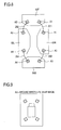
- the curves 201, 202, 203, and 204 indicate the correspondence between calibration patterns on different bird's-eye view images, and conceptually illustrates the rigid body conversion performed at each relevant place.
- the image processing apparatus 10 previously recognizes the correspondence between the calibration patterns and characteristic points acquired by different cameras. Specifically, for example, the image processing apparatus 10 previously recognizes which calibration patterns and characteristic points included in the image shot with the camera 1F correspond to which calibration patterns and characteristic points included in the image shot with the camera 1R (or 1L). The same is true between the other cameras. This makes rigid body conversion as described above possible.
- the translation matrices expressing the translation to be performed on the bird's-eye view images 50F, 50R, 50L, and 50B are represented by T 1 , T 2 , T 3 , and T 4 respectively, and the rotation matrices expressing the rotation to be performed on the bird's-eye view images 50F, 50R, 50L, and 50B are represented by R 1 , R 2 , R 3 , and R 4 respectively.
- the coordinates of a point on the all-around bird's-eye view image are represented by (X', Y'). Then, the coordinates (x n , y n ) of a point on a shot image are converted to the coordinates (X', Y') of a point on the all-around bird's-eye view image by use of a homography matrix H n ' according to formulae (3a) and (3b) below.
- the translation matrix T n and the rotation matrix R n are expressed by formulae (4a) and (4b) below.
- the individual elements of the homography matrix H n ' are expressed by formula (5) below.
- the coordinate system (coordinates) on the all-around bird's-eye view image is called the global coordinate system (global coordinates).
- the global coordinate system is a coordinate system defined to be common to all the cameras.
- Each homography matrix H n ' is found at the initial calibration stage. In the process of projecting a shot image onto the ground to produce a bird's-eye view image, however, various error factors produce projection errors (positional errors from ideal projection positions). To cope with this, after each homography matrix H n ' is found at the initial calibration stage, then at the adjustment stage, the individual elements (8 x 4 elements) of each of H 1 ' to H 4 are optimized. The optimization is achieved, for example, by minimizing the projection errors of the characteristic points in each calibration pattern. By optimizing each homography matrix in this way, it is possible to obtain an accurate all-around bird's-eye view image in which its component images are merged together smoothly at their borders. Fig.
- FIG. 9 shows an example of the thus produced all-around bird's-eye view image.
- an image having an image of the vehicle 100 fitted in the produced all-around bird's-eye view image is displayed on the display apparatus 11 shown in Fig. 5 .
- Fig. 10 is a flow chart showing the procedure of the calibration processing in Example 1.
- the calibration processing includes operations in steps S11 to S 14, with step S11 executed by each camera and the image processing apparatus 10, and steps S 12 to S 14 executed by the image processing apparatus 10.
- step S11 With the calibration patterns arranged within the corresponding common shooting areas as described previously (see Fig. 6 ), the cameras shoot them, and the image processing apparatus 10 acquires shot images from the cameras respectively.
- the shot images acquired here will henceforth be specially called the "shot-for-calibration images".
- Fig. 11 shows an example of the thus acquired shot-for-calibration images.
- reference signs 301, 302, 303, and 304 indicate the shot-for-calibration images from the cameras 1F, 1R, 1L, and 1B respectively.
- step S12 by planar projection conversion, bird's-eye view conversion is performed on the individual shot-for-calibration images.
- bird's-eye view conversion denotes processing for converting shot images (including shot-for-calibration images) to bird's-eye view images.
- Fig. 12 shows a bird's-eye view image 313 obtained by performing bird's-eye view conversion on a shot-for-calibration image 303.
- shot images including shot-for-calibration images
- image processing such as correction of lens-induced distortion
- step S12 the homography matrix H n for converting the shot-for-calibration images into bird's-eye view images is found. Now, the method for finding the homography matrix H 1 will be described.
- the image processing apparatus 10 performs edge detection or the like on the shot-for-calibration image from the camera 1F and thereby identifies the coordinates of the four characteristic points of the calibration pattern A1 on the shot-for-calibration image from the camera 1F.
- the thus identified coordinates of the four points are represented by (x A1a , y A1a ), (x A1b , y A1b ), (x A1c , y A1c ), and (x A1d , y A1d ).
- the image processing apparatus 10 determines the coordinates of the four characteristic points of the calibration pattern A1 on the bird's-eye view image corresponding to the camera 1F.
- the thus defined coordinates of the four points are represented by (X A1a , Y A1a ), (X A1b , Y A1b ), (X A1c , Y A1c ), and (X A1d , Y A1d ). Since the calibration pattern A1 is square in shape, the coordinates (X A1a , Y A1a ), (X A1b , Y A1b ), (X A1c , Y A1c ), and (X A1d , Y A1d ) can be defined to be, for example, (0, 0), (1, 0), (0, 1), and (1, 1).
- the above description deals with an example in which the homography matrix H 1 is found based on the coordinates of the four characteristic points of the calibration pattern A1, it is also possible to find the homography matrix H 1 based on the coordinates of the four characteristic points of the calibration pattern A2.
- the method for finding the homography matrix H 1 based on the four characteristic points of either the calibration pattern A1 or A2 has been described first; it is, however, preferable to find the homography matrix H 1 based on the coordinates of a total of eight characteristic points of both the calibration patterns A1 and A2.
- the calibration pattern A1 (or A2) appears precisely square as previously known; on the other hand, the calibration pattern A2 (or A1) usually does not appear square. This is ascribable to coordinate errors and the like of the characteristic points identified on the shot-for-calibration images.
- the bird's-eye view image obtained through conversion according to the homography matrix H 1 based on the eight characteristic points of both the calibration patterns A1 and A2 projection errors diffuse over both the calibration patterns A1 and A2.
- any point on a shot-for-calibration image can be converted to a point on a bird's-eye view image according to formulae (2a) and (2b) above.
- step S13 the individual bird's-eye view images obtained in step S12 are subjected to position adjustment by rigid body conversion (translation and rotation) such that the coordinates of mutually corresponding calibration patterns coincide. It is assumed that the bird's-eye view images obtained through bird's-eye view conversion of the shot-for-calibration images from the cameras 1F, 1R, 1L, and 1B are the bird's-eye view images 50F, 50R, 50L, and 50B, respectively, shown in Fig. 8 .
- the bird's-eye view image 50R is subjected to rigid body conversion such that the calibration pattern A1 on the bird's-eye view image 50F and the calibration pattern A1 on the bird's-eye view image 50R coincide
- the bird's-eye view image 50L is subjected to rigid body conversion such that the calibration pattern A2 on the bird's-eye view image 50F and the calibration pattern A2 on the bird's-eye view image 50L coincide.
- the bird's-eye view image 50B is subjected to rigid body conversion such that the calibration patterns A3 and A4 on the bird's-eye view image 50B and the calibration patterns A3 and A4 on the bird's-eye view images 50R and 50L after rigid body conversion coincide.
- the homography matrix H n ' is calculated (see formula (3b) etc. above).
- the homography matrix H n ' calculated here can be regarded as the initial value of the homography matrix H n ' to be definitively found, and is then optimized in the next step, S14. That is, in step S13, initial calibration of homography matrices is performed.
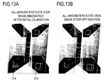
- Fig. 13A shows the image merged as the result of the rigid body conversion in step S13, that is, the all-around bird's-eye view image immediately after initial calibration.
- the top part of the diagram corresponds to the bird's-eye view image 50F
- the bottom part of the diagram corresponds to the bird's-eye view image 50B.
- the calibration patterns A3 and A4 each appear doubly. This is because, through rigid body conversion as described above, errors accumulate in the bird's-eye view image 50B definitively merged.
- the homography matrix H 4 ' for the camera 1B is, alone, optimized. Specifically, on the assumption that no errors are included in the coordinate positions of the calibration patterns A3 and A4 on the bird's-eye view images 50R and 50L after rigid body conversion, a homography matrix is found that permits, as shown in Fig. 14 , the coordinates of the individual characteristic points of the calibration patterns A3 and A4 on the shot-for-calibration image from the camera 1B to be converted to the coordinates of the individual characteristic points of the calibration patterns A3 and A4 on the bird's-eye view images 50R and 50L after rigid body conversion. Then, the thus found homography matrix is dealt with the definitive homography matrix H 4 '.
- step S13 the bird's-eye view image 50B is subjected to rigid body conversion to find the initial value of the homography matrix H 4 '.
- step S14 it is not really necessary to calculate the homography matrix H 4 ' at the stage of step S 13.
- Fig. 13B shows the all-around bird's-eye view image produced by use of the homography matrix H n ' having undergone the optimization in step S14.
- Fig. 13B shows the double appearance etc. observed in the all-around bird's-eye view image shown in Fig. 13A has been alleviated.
- step S14 Through bird's-eye view conversion and rigid body conversion, the points on each shot-for-calibration image are converted to points on the global coordinate system. It is assumed that, as the result of the individual characteristic points of the calibration pattern A3 on the shot-for-calibration image from the camera 1R being projected onto the global coordinate system according to the homography matrix H 2 ', the calibration pattern A3 corresponding to the camera 1R describes a quadrangle 340 as shown in Fig. 15 on the global coordinate system.
- the calibration pattern A3 corresponding to the camera 1B describes a quadrangle 350 as shown in Fig. 15 on the global coordinate system.
- the quadrangle 340 is formed by four vertices 341 to 344 corresponding to the projected points of the four characteristic points on the global coordinate system
- the quadrangle 350 is formed by four vertices 351 to 354 corresponding to the projected points of the four characteristic points on the global coordinate system.
- the vertices 341, 342, 343, and 344 corresponds to the vertices 351, 352, 353, and 354 respectively.
- the positional error between the vertices 341 and 351, the positional error between the vertices 342 and 352, the positional error between the vertices 343 and 353, and the positional error between the vertices 344 and 354 are represented by d1, d2, d3, and d4 respectively.
- a positional error is the distance between compared vertices.
- the positional error d1 is the distance between the vertices 341 and 351.
- the positional errors d2 to d4 Positional errors like these also occur with respect to the calibration pattern A4 between the cameras 1L and 1B.
- the four positional errors with respect to the calibration pattern A3 and the four positional errors with respect to the calibration pattern A4 are referred to.
- the sum total of these eight positional errors in total is referred to as the error evaluation value D A . Since a positional error is the distance between compared vertices, it always takes a zero or positive value.
- step S 14 the homography matrix H 4 is found that makes the error evaluation value D A minimal. More specifically, the homography matrix H 4 ' is adjusted through repeated calculations until the error evaluation value D A becomes equal to or less than a predetermined threshold value.
- the homography matrix H 1 ' to H 3 ' calculated in step S13 in Fig. 10 and the homography matrix H 4 ' definitively calculated in step S 14 are dealt with as the calibrated conversion parameters for producing an all-around bird's-eye view image from shot images. Thereafter, the calibration processing shown in Fig. 10 is ended.
- table data is created that indicates the correspondence between coordinates (x n , y n ) on shot images and coordinates (X', Y') on an all-around bird's-eye view image, and the table data is stored in an unillustrated memory (lookup table).
- lookup table an unillustrated memory
- the table data may be regarded as the calibrated conversion parameters.
- an automatic detection method employing image processing as described above may be adopted; instead, a manual detection method may be adopted that relies on manual operations made on an operated portion (unillustrated).
- a manual detection method may be adopted that relies on manual operations made on an operated portion (unillustrated).
- D A error evaluation value
- one of generally known methods is used. For example, it is possible to use a multiple-dimensional downhill simplex method, the Powell method, or the like (see, for example, "Numerical Recipes in C" by William H. Press et al., Gijutsu-Hyoron-Sha, 1993). Since these methods are well known, no description of any will be given here.
- the image processing apparatus 10 shown in Fig. 5 converts the shot images obtained from the individual cameras one set after another to one all-around bird's-eye view image after another.
- the image processing apparatus 10 feeds the video signal representing one all-around bird's-eye view image after another to the display apparatus 11.
- the display apparatus 11 thus displays the all-around bird's-eye view images as a moving image.
- Example 1 images shot with the cameras 1F, 1R, and 1L are projected by planar projection conversion, and the resulting bird's-eye view images are then subjected to position adjustment such that common calibration patterns coincide, in order to thereby find homography matrices H 1 ' to H 3 ' for subjecting the images shot with the cameras 1F, 1R, and 1L to coordinate conversion onto a global coordinate system.
- homography matrices H 2 ' and H 3 ' calibration patterns A3 and A4 shot with the cameras 1R and 1L are subjected to coordinate conversion onto the global coordinate system.
- a homography matrix H 4 ' is found such that the arrangements of common calibration patterns largely coincide on the global coordinate system (see Fig 14 ).
- the homography matrices H 1 ' to H 3 ' found first and the homography matrix H 4 ' found thereafter are together regarded as calibrated conversion parameters.
- the image processing apparatus 10 includes a first parameter deriver for finding homography matrices H 1 ' to H 3 ' as first parameters and a second parameter deriver for finding a homography matrix H 4 ' as second parameters.
- Example 1 a person who is going to perform calibration processing simply has to arrange calibration patterns inside the corresponding common shooting areas without paying any further attention to their arrangement positions. Moreover, each calibration pattern can be made significantly smaller than the overall shooting area of all cameras or even the shooting area of each camera. This helps simplify the setting-up of a calibration environment. Moreover, there is no need for camera external information, such as the angle and height at which a camera is installed, or camera internal information, such as the focal length of the camera. This contributes to simplified calibration operation. Furthermore, adjustment processing as in step S14 makes it possible to merge a plurality of images together smoothly at their seams.
- Fig. 16 is a flow chart showing the procedure of the calibration processing in Example 2.
- the calibration processing includes operations in steps S 11 to S 13 and an operation in step S24.
- the operations in steps S 11 to S 13 are the same as those in Example 1 ( Fig. 10 ).
- step S13 the individual bird's-eye view images obtained in step S12 are subjected to position adjustment by rigid body conversion and are merged together such that the coordinates of mutually corresponding calibration patterns coincide.
- the projected points of characteristic points on the merged image usually do not completely coincide between two cameras.
- this non-coincidence of projected points is reduced in step S14; in Example 2, the non-coincidence of projected points is reduced in step S24.
- Figs. 17A to 17D are diagrams schematically showing the flow of the calibration processing shown in Fig. 16 , with special attention paid to the operation in step S24.
- Example 2 after the bird's-eye view conversion in step S12, then, in step S13, the individual bird's-eye view images are subjected to position adjustment by rigid body conversion, and then an advance is made to step S24.
- the points on the individual shot-for-calibration images are projected onto the corresponding points on the global coordinate system.
- Fig. 17A shows how the calibration patterns appears on the global coordinate system immediately after the position adjustment in step S13 (immediately after initial calibration).
- the projected image of the calibration pattern A1 on the global coordinate system as observed immediately after the position adjustment in step S13 is shown in Fig. 18A .
- the calibration pattern A1 corresponding to the camera 1F describes a quadrangle 370 on the global coordinate system. It is also assumed that, as the result of the individual characteristic points of the calibration pattern A1 on the shot-for-calibration image from the camera 1R being projected onto the global coordinate system according to the homography matrix H 2 ' calculated in step S 13, the calibration pattern A1 corresponding to the camera 1 R describes a quadrangle 380 on the global coordinate system.
- the quadrangle 370 is formed by four vertices 371 to 374 corresponding to the projected points of the four characteristic points on the global coordinate system
- the quadrangle 380 is formed by four vertices 381 to 384 corresponding to the projected points of the four characteristic points on the global coordinate system. It is further assumed that the vertices 371, 372, 373, and 374 corresponds to the vertices 381, 382, 383, and 384 respectively.
- the image processing apparatus 10 finds the midpoint 391 between the vertices 371 and 381, the midpoint 392 between the vertices 372 and 382, the midpoint 393 between the vertices 373 and 383, and the midpoint 394 between the vertices 374 and 384, and thereby finds a quadrangle 390 having as its four vertices the midpoints 391, 392, 393, and 394.
- Fig. 18B shows the quadrangle 390.
- the quadrangle 390 is the average quadrangle of the quadrangles 370 and 380. The appearance at the stage that the average quadrangle has just been calculated is shown in Fig. 17B . Due to error factors, the quadrangles 370, 380, and 390 often do not appear square as previously known.
- the image processing apparatus 10 previously recognizes the shapes of the calibration patterns as they should ideally appear on the global coordinate system. As shown in Fig. 18B , the image processing apparatus 10 overlays a square 400 with that ideal shape on the quadrangle 390, and finds the position of the square 400 that makes minimal the sum total of the positional errors between the vertices of the quadrangle 390 and the corresponding vertices of the square 400. The sum total of the positional errors is calculated in a similar manner to (d1 + d2 + d3 + d4) between the quadrangles 340 and 350 in Fig. 15 .
- the square 400 On the global coordinate system, with the center of gravity of the square 400 placed at that of the quadrangle 390, the square 400 is rotated about its center of gravity to search for the above-mentioned minimal total sum.
- the positions of the four vertices of the square 400 that make the sum total minimal are determined as the projection target points onto which the calibration pattern A1 should be projected.
- Fig. 19 shows the thus found projection target points (16 points in total) onto which the individual characteristic points of the calibration patterns should be projected. In this way, correction is performed such that the shapes of the figures formed by the projection target points appear square.
- Fig. 17C shows the appearance at the stage that this correction has just been performed.
- step S24 the homography matrix H 1 ' is recalculated such that the four characteristic points of the calibration pattern A1 on the shot-for-calibration image from the camera 1F are projected onto the four projection target points for the calibration pattern A1 and that the four characteristic points of the calibration pattern A2 on the shot-for-calibration image from the camera 1F are projected onto the four projection target points for the calibration pattern A2.
- a homography matrix H 1 ' that completely fulfills that often cannot be found uniquely; thus, as in the above described optimization of a homography matrix through the calculation of an error evaluation value D A , it is advisable to find the homography matrix H 1 ' that makes minimal the sum total of the positional errors (a total of eight positional errors occur) between the actually projected points and the projection target points.
- the homography matrices H 2 ' to H 4 ' are recalculated.
- the homography matrix H 2 ' is recalculated such that the four characteristic points of the calibration pattern A1 on the shot-for-calibration image from the camera 1R are projected onto the four projection target points for the calibration pattern A1 and that the four characteristic points of the calibration pattern A3 on the shot-for-calibration image from the camera 1R are projected onto the four projection target points for the calibration pattern A3.
- Fig. 17D shows the all-around bird's-eye view image obtained after the recalculation of all the homography matrices.
- the homography matrices H 1 ' to H 4 ' definitively obtained through the recalculation in step S24 are dealt with as the calibrated conversion parameters for producing the all-around bird's-eye view image from the shot images. Thereafter, the calibration processing shown in Fig. 16 is ended.
- table data is created like that described previously in connection with Example 1. In this case, the table data may be regarded as the calibrated conversion parameters.
- the image processing apparatus 10 shown in Fig. 5 converts the shot images obtained from the individual cameras one set after another to one all-around bird's-eye view image after another.
- the image processing apparatus 10 feeds the video signal representing one all-around bird's-eye view image after another to the display apparatus 11.
- the display apparatus 11 thus displays the all-around bird's-eye view images as a moving image.
- Example 2 first, rigid body conversion is performed such that, between each pair of cameras that shoots a common calibration pattern (that is, individually between the cameras 1F and 1R, between the cameras 1F and 1L, between the cameras 1B and 1L, and between the cameras 1B and 1R), the positions of the common calibration pattern largely coincide on the global coordinate system, to thereby tentatively find the homography matrices H 1 ' to H 4 '.
- the calibration patterns are subjected to coordinate conversion onto the global coordinate system.
- the homography matrices H 1 ' to H 4 ' are optimized through the correction of the shapes of the thus coordinate-converted calibration patterns on the global coordinate system.
- Example 2 offers the same benefits as Example 1.
- the calibration processing according to Example 2 is particularly effective in cases where the accuracy of initial calibration is not high.
- Example 3 will be described as a practical example for explaining another method of optimizing the homography matrices H 1 ' to H 4 '.
- Example 3 is a modified example of Example 2.
- the calibration processing in Example 3 proceeds according to the same flow chart ( Fig. 16 ) as in Example 2, and includes operations in steps S 11 to S13 and an operation in step S24.
- the optimization of the homography matrices H 1 ' to H 4 ' in step S24 is performed by a method different than in Example 2. Accordingly, the following description focuses on the differences from Example 2 - the method of the optimization in Example 3.
- the calibration patterns are square in shape.
- a square remains identical with respect to rotation, which has one degree of freedom, and with respect to translation, which has two degrees of freedom. Accordingly, whereas a common planar projection conversion matrix has eight degrees of freedom, the homography matrix H n or H n ' dealt with in Example 3 has five or less degrees of freedom.
- one side of the calibration pattern A1 on the global coordinate system is fixed. With one side of the calibration pattern A1 on the global coordinate system fixed, by use of coordinate information on the individual characteristic points of the calibration patterns A2 and A3, it is possible to uniquely determine the arrangement positions of the individual bird's-eye view images on the all-around bird's-eye view image.
- one side of the calibration pattern A1 on the bird's-eye view image 50F and one side, corresponding to the just-mentioned side, of the calibration pattern A1 on the bird's-eye view image 50R are made to completely coincide, and in addition the coordinate positions of both ends of that one side on the global coordinate system are uniquely determined. That is, the homography matrices H 1 ' and H 2 ' are adjusted in that way.
- the bird's-eye view images 50L and 50B are subjected to position adjustment by rigid body conversion such that, on the global coordinate system, the calibration pattern A2 on the bird's-eye view image 50F and the calibration pattern A2 on the bird's-eye view image 50L coincide (largely coincide) and the calibration pattern A3 on the bird's-eye view image 50R and the calibration pattern A3 on the bird's-eye view image 50B coincide (largely coincide).
- the homography matrices H 3 ' and H 4 ' are tentatively found.
- the arrangement positions of the individual bird's-eye view images on the global coordinate system are uniquely determined.
- the side represented by a solid line indicated by reference sign 450 is the side of which the coordinate positions of both ends on the global coordinate system have been uniquely determined.
- the length of the side 450 is equal to the length of each side of the previously known square according to previously known information.
- Fig. 21 shows the image obtained by projecting the shot-for-calibration image from the camera 1F onto the global coordinate system by use of the initial value of the homography matrix H 1 ' (that is, the bird's-eye view image 50F after the position adjustment described above).
- quadrangles 460 and 480 represent the projected figures into which the calibration patterns A1 and A2, respectively, are actually projected.
- the side indicated by reference sign 450 is the same as that in Fig. 20 .
- One side of the quadrangle 460 corresponding to the calibration pattern A1 completely coincides with the side 450.
- the previously known squares 470 and 490 according to the previously known information are overlaid on the quadrangles 460 and 480 such as to largely coincide with them.
- the following restricting conditions are applied: one side of the square 470 is made to coincide with the side 450; and one vertex of the square 490 is made to coincide with one vertex of the quadrangle 480, and the sides of the square 490 and of the quadrangle 480 which have at their one end the vertices thus made to coincide are made to overlap.
- Positional errors like these also occur in the image obtained by projecting the shot-for-calibration image from the camera 1R onto the global coordinate system by use of the initial value of the homography matrix H 2 '.
- the following restricting conditions are applied: one vertex of the calibration pattern A2 is made to coincide with one vertex of a previously known square, and the sides of the calibration pattern A2 and of the previously known square which have at their one end the vertices thus made to coincide are made to overlap; one vertex of the calibration pattern A4 is made to coincide with one vertex of a previously known square, and the sides of the calibration pattern A4 and of the previously known square which have at their one end the vertices thus made to coincide are made to overlap.
- Example 3 the sum total of these 22 positional errors in total is taken as an error evaluation value D B , and each homography matrix H n is optimized such that the error evaluation value D B is minimized.
- D B a method similar to that used to minimize the error evaluation value D A in Example 1 is used.
- the optimized homography matrices H 1 ' to H 4 ' are dealt with as the calibrated conversion parameters for producing an all-around bird's-eye view image from shot images. Thereafter, the calibration processing according to Example 3 is ended.
- table data is created like that described previously in connection with Example 1. In this case, the table data may be regarded as the calibrated conversion parameters.
- the image processing apparatus 10 shown in Fig. 5 converts the shot images obtained from the individual cameras one set after another to one all-around bird's-eye view image after another.
- the image processing apparatus 10 feeds the video signal representing one all-around bird's-eye view image after another to the display apparatus 11.
- the display apparatus 11 thus displays the all-around bird's-eye view images as a moving image.
- initial calibration is achieved by planar projection conversion. That is, bird's-eye view conversion is performed by planar projection conversion, and then, by rigid body conversion, the initial value of the homography matrix H n ' is found.
- planar projection conversion may be used in initial calibration. How perspective projection conversion is used in such a case will now be described as Example 4.
- Perspective projection conversion is generally known (see, for example, JP-2006-287892 ).
- a method for converting an image shot with a single camera into a bird's-eye view image by perspective projection conversion will now be described briefly.
- the coordinates of a point on the shot image are represented by (x bu , y bu ), and the coordinates of a point on the bird's-eye view image obtained through perspective projection conversion of the shot image are represented by (x au , y au ) ⁇
- the conversion of coordinates (x bu , y bu ) to coordinates (x au , y au ) is performed according to formula (7) below.
- x au y au x bu ⁇ fh ⁇ sin ⁇ a + H a ⁇ y au ⁇ cos ⁇ a f ⁇ H a fh ⁇ f ⁇ cos ⁇ a - y bu ⁇ sin ⁇ a H a ⁇ f ⁇ sin ⁇ a + y bu ⁇ cos ⁇ a
- the symbol ⁇ a represents, as shown in Fig. 22 , the angle between the ground and the optical axis of a camera (90° ⁇ ⁇ a ⁇ 180°).
- the camera is assumed to be, for example, the camera 1B.
- the symbol h represents a quantity based on the height of the camera (the translational displacement, in the direction of height, between the camera coordinate system and the world coordinate system).
- the symbol f represents the focal length of the camera.
- an image actually shot with the camera is converted into an image as if viewed from the point of view (virtual viewpoint) of a virtual camera.
- the symbol H a represents the height of this virtual camera.
- the values ⁇ a , h, and H a can be regarded as camera external information (external parameters of the camera), and the value f can be regarded as camera internal information (an internal parameter of the camera).
- the image processing apparatus 10 previously recognizes, as necessary for perspective projection conversion, the values ⁇ a , h, f, and H a for each camera, and produces individual bird's-eye view images through coordinate conversion of the points on shot-for-calibration images from different cameras according to formula (7). Thereafter, the image processing apparatus 10 adjusts the positions of the individual bird's-eye view images through rigid body conversion of those bird's-eye view images by a similar method as in one of Examples 1 to 3.
- the image processing apparatus 10 finds the initial value of each homography matrix H n '.
- Example 1 When Example 1 is applied to Example 4, the processing proceeds as follows. First, by perspective projection conversion, individual bird's-eye view images are obtained. Then, only the bird's-eye view images corresponding to the cameras 1F, 1R, and 1L are subjected to position adjustment by rigid body conversion. Then, based on the correspondence between the coordinates of the individual characteristic points of the calibration patterns on these position-adjusted bird's-eye view images (their coordinates on the global coordinate system) and the coordinates of the individual characteristic points of the calibration patterns on the shot-for-calibration images (their coordinates on the shot-for-calibration images), the homography matrices H 1 ' to H 3 ' are found. Then, as described previously in connection with Example 1, while the error evaluation value D A is minimized, the homography matrix H 4 ' is found.
- Note 1 To perform planar projection conversion, four characteristic points are needed between the pre-conversion image and the post-conversion image. In view of this, in the embodiments described above, square calibration patterns each having four characteristic points are adopted. The calibration patterns, however, do not necessarily have to be square.
- each calibration pattern has only to include a total of two or more characteristic points.
- calibration patterns a1, a2, a3, and a4 each having the shape of a line segment may be arranged in common shooting areas 3 FR , 3 FL , 3 BR , and 3 BL respectively; this, too, permits adjustment of the homography matrix H n ' through rigid body conversion on the individual bird's-eye view images.
- Fig. 24 shows how rigid body conversion is performed by use of the calibration patterns a1 to a4.
- the calibration patterns a1 to a4 each include, as characteristic points, both ends of a line segment, and the length of the line segment on the global coordinate system is previously known. So long as the calibration patterns arranged respectively within the common shooting areas each include two or more characteristic points, by referring to the positional errors between projected points that should ideally coincide on the global coordinate system, it is possible to adjust and improve the homography matrix H n '.
- bird's-eye view images are images in which images shot with cameras are projected onto the ground. That is, in the embodiments described above, an all-around bird's-eye view image is produced by projecting images shot with cameras onto the ground and merging them together. Instead, the shot images may be projected on any predetermined surface (for example, a predetermined plane) other than the ground that is arbitrarily selected.
- the invention has been described by way of embodiments that deal with a field-of-view assistance system employing the cameras 1F, 1R, 1L, and 1B as vehicle-mounted cameras, the cameras connected to the image processing apparatus 10 may be fitted to anything other than a vehicle. That is, the invention may be applied as well to a monitoring system installed in a building or the like. In such a monitoring system, as in the embodiments described above, shot images from a plurality of cameras are projected onto a predetermined surface and merged together, and the merged image is displayed on a display apparatus.
- the functions of the image processing apparatus 10 can be realized in hardware, in software, or in a combination of hardware and software. All or part of the functions to be realized by the image processing apparatus 10 may be prepared in the form of a computer program so that those functions are, wholly or partly, realized as the program is executed on a computer.
- the parameter deriver that, in calibration processing, adjusts conversion parameters and thereby derives calibrated conversion parameters is incorporated in the image processing apparatus 10, and the camera calibration apparatus that is provided with the parameter deriver and that performs calibration processing for the cameras is also incorporated in the image processing apparatus 10.
- the parameter deriver includes a tentative parameter deriver that finds conversion parameters (a homography matrix H n ') tentatively and a parameter adjuster that adjusts the tentative conversion parameters.
- the image processing apparatus 10 functions as a merged image producer that projects shot images onto a predetermined surface and merges them together to thereby produce a merged image (in the embodiments described above, an all-around bird's-eye view image).
Applications Claiming Priority (1)
| Application Number | Priority Date | Filing Date | Title |
|---|---|---|---|
| JP2007020503A JP2008187566A (ja) | 2007-01-31 | 2007-01-31 | カメラ校正装置及び方法並びに車両 |
Publications (2)
| Publication Number | Publication Date |
|---|---|
| EP1968011A2 true EP1968011A2 (fr) | 2008-09-10 |
| EP1968011A3 EP1968011A3 (fr) | 2011-03-09 |
Family
ID=39315389
Family Applications (1)
| Application Number | Title | Priority Date | Filing Date |
|---|---|---|---|
| EP08001730A Withdrawn EP1968011A3 (fr) | 2007-01-31 | 2008-01-30 | Procédé et appareil pour l'étalonnage d'une caméra, et véhicule |
Country Status (4)
| Country | Link |
|---|---|
| US (1) | US20080231710A1 (fr) |
| EP (1) | EP1968011A3 (fr) |
| JP (1) | JP2008187566A (fr) |
| CN (1) | CN101236654A (fr) |
Cited By (7)
| Publication number | Priority date | Publication date | Assignee | Title |
|---|---|---|---|---|
| EP2200311A1 (fr) * | 2007-10-18 | 2010-06-23 | Sanyo Electric Co., Ltd. | Dispositif et procédé de calibration de caméra, et véhicule |
| EP1954063A3 (fr) * | 2007-02-01 | 2011-03-02 | Sanyo Electric Co., Ltd. | Procédé et appareil pour l'étalonnage d'une caméra et véhicule |
| EP2339535A1 (fr) * | 2009-11-17 | 2011-06-29 | Fujitsu Limited | Appareil d'étalonnage et procédé d'étalonnage |
| CN103198481A (zh) * | 2013-04-03 | 2013-07-10 | 天津大学 | 一种摄像机标定方法及其实现系统 |
| EP2590408A4 (fr) * | 2010-06-29 | 2016-01-27 | Clarion Co Ltd | Procédé et dispositif d'étalonnage d'image |
| EP2711895A3 (fr) * | 2012-09-24 | 2017-03-01 | Clarion Co., Ltd. | Procédé et appareil d'étalonnage de caméra embarquée |
| EP3157786B1 (fr) | 2014-06-20 | 2019-03-06 | KNORR-BREMSE Systeme für Nutzfahrzeuge GmbH | Véhicule comprenant un dispositif de surveillance de l'environnement et procédé permettant de faire fonctionner un dispositif de surveillance de l'environnement de ce type |
Families Citing this family (90)
| Publication number | Priority date | Publication date | Assignee | Title |
|---|---|---|---|---|
| AU2003225228A1 (en) | 2002-05-03 | 2003-11-17 | Donnelly Corporation | Object detection system for vehicle |
| US7526103B2 (en) | 2004-04-15 | 2009-04-28 | Donnelly Corporation | Imaging system for vehicle |
| WO2008024639A2 (fr) | 2006-08-11 | 2008-02-28 | Donnelly Corporation | Système de commande automatique de phare de véhicule |
| JP2009104323A (ja) * | 2007-10-22 | 2009-05-14 | Alpine Electronics Inc | マッピングテーブル生成装置、車両周辺画像生成装置およびマッピングテーブル生成方法 |
| KR101093316B1 (ko) | 2008-04-15 | 2011-12-14 | 주식회사 만도 | 차량주행중 영상정합 방법 및 그 시스템 |
| JP4555876B2 (ja) * | 2008-05-30 | 2010-10-06 | 株式会社日本自動車部品総合研究所 | 車載カメラのキャリブレーション方法 |
| JP2010041530A (ja) * | 2008-08-07 | 2010-02-18 | Sanyo Electric Co Ltd | 操縦支援装置 |
| JP2010093605A (ja) * | 2008-10-09 | 2010-04-22 | Sanyo Electric Co Ltd | 操縦支援装置 |
| JP5387580B2 (ja) * | 2008-11-05 | 2014-01-15 | 富士通株式会社 | カメラ角度算出装置およびカメラ角度算出方法 |
| DE102008061760A1 (de) * | 2008-12-12 | 2010-06-17 | Daimler Ag | Vorrichtung zur Überwachung einer Umgebung eines Fahrzeugs |
| KR100966288B1 (ko) | 2009-01-06 | 2010-06-28 | 주식회사 이미지넥스트 | 주변 영상 생성 방법 및 장치 |
| JP5456330B2 (ja) * | 2009-02-04 | 2014-03-26 | アルパイン株式会社 | 画像表示装置及びそのカメラ取り付け角度算出方法 |
| JP4751939B2 (ja) * | 2009-03-31 | 2011-08-17 | アイシン精機株式会社 | 車載カメラの校正装置 |
| KR101023275B1 (ko) | 2009-04-06 | 2011-03-18 | 삼성전기주식회사 | 차량용 카메라 시스템의 캘리브레이션 방법 및 장치, 차량용 카메라 시스템의 각도상 오정렬을 판단하는 방법 및 이를 수행하는 전자 제어 유닛 |
| JP5523730B2 (ja) * | 2009-04-07 | 2014-06-18 | アルパイン株式会社 | 車載周辺画像表示装置 |
| KR100956858B1 (ko) | 2009-05-19 | 2010-05-11 | 주식회사 이미지넥스트 | 차량 주변 영상을 이용하는 차선 이탈 감지 방법 및 장치 |
| JP2010273091A (ja) * | 2009-05-21 | 2010-12-02 | Nippon Telegr & Teleph Corp <Ntt> | 広域多視点カメラ校正方法、広域多視点カメラ校正装置、およびプログラム |
| KR100948886B1 (ko) | 2009-06-25 | 2010-03-24 | 주식회사 이미지넥스트 | 차량에 설치된 카메라의 공차 보정 장치 및 방법 |
| JP5271186B2 (ja) * | 2009-07-28 | 2013-08-21 | 東芝アルパイン・オートモティブテクノロジー株式会社 | 車両用画像表示装置 |
| TW201103787A (en) * | 2009-07-31 | 2011-02-01 | Automotive Res & Testing Ct | Obstacle determination system and method utilizing bird's-eye images |
| DE102009036200A1 (de) * | 2009-08-05 | 2010-05-06 | Daimler Ag | Verfahren zur Überwachung einer Umgebung eines Fahrzeugs |
| TWI392366B (zh) * | 2009-12-31 | 2013-04-01 | Ind Tech Res Inst | 全周鳥瞰影像距離介面產生方法與系統 |
| KR101510655B1 (ko) * | 2010-01-26 | 2015-04-10 | 주식회사 이미지넥스트 | 주변 영상 생성 방법 및 장치 |
| JP5491235B2 (ja) * | 2010-03-02 | 2014-05-14 | 東芝アルパイン・オートモティブテクノロジー株式会社 | カメラキャリブレーション装置 |
| CN102194212B (zh) * | 2010-03-08 | 2013-09-25 | 佳能株式会社 | 图像处理方法、装置及系统 |
| JP5548002B2 (ja) * | 2010-03-25 | 2014-07-16 | 富士通テン株式会社 | 画像生成装置、画像表示システム及び画像生成方法 |
| JP5552892B2 (ja) * | 2010-05-13 | 2014-07-16 | 富士通株式会社 | 画像処理装置および画像処理プログラム |
| JP5402832B2 (ja) * | 2010-05-27 | 2014-01-29 | 株式会社Jvcケンウッド | 視点変換装置及び視点変換方法 |
| CN101957990B (zh) * | 2010-08-13 | 2012-07-04 | 武汉大学 | 一种摄像机定标方法、图像处理设备和机动车辆 |
| CN102045546B (zh) * | 2010-12-15 | 2013-07-31 | 广州致远电子股份有限公司 | 一种全景泊车辅助系统 |
| EP2511137B1 (fr) | 2011-04-14 | 2019-03-27 | Harman Becker Automotive Systems GmbH | Système de visualisation panoramique de véhicule |
| WO2012145822A1 (fr) | 2011-04-25 | 2012-11-01 | Magna International Inc. | Procédé et système pour étalonner de façon dynamique des caméras de véhicule |
| EP2523163B1 (fr) * | 2011-05-10 | 2019-10-16 | Harman Becker Automotive Systems GmbH | Méthode et programme pour la calibration d'un système multicaméra |
| EP2530647A1 (fr) | 2011-06-01 | 2012-12-05 | Harman Becker Automotive Systems GmbH | Procédé d'étalonnage d'un système de vision de véhicule et système de vision de véhicule |
| EP2541498B1 (fr) | 2011-06-30 | 2017-09-06 | Harman Becker Automotive Systems GmbH | Procédé pour définir les paramètres extrinsèques d'un système de vision de véhicule et système de vision de véhicule |
| EP2554434B1 (fr) | 2011-08-05 | 2014-05-21 | Harman Becker Automotive Systems GmbH | Système de visualisation panoramique de véhicule |
| US9491451B2 (en) | 2011-11-15 | 2016-11-08 | Magna Electronics Inc. | Calibration system and method for vehicular surround vision system |
| WO2013086249A2 (fr) | 2011-12-09 | 2013-06-13 | Magna Electronics, Inc. | Système de vision pour véhicule avec affichage personnalisé |
| US10457209B2 (en) * | 2012-02-22 | 2019-10-29 | Magna Electronics Inc. | Vehicle vision system with multi-paned view |
| WO2013126715A2 (fr) | 2012-02-22 | 2013-08-29 | Magna Electronics, Inc. | Système de caméra de véhicule à manipulation d'image |
| KR101331893B1 (ko) | 2012-04-13 | 2013-11-26 | 주식회사 이미지넥스트 | 차량 설치 카메라 외부 파라미터 추정 방법 및 장치 |
| WO2013158592A2 (fr) | 2012-04-16 | 2013-10-24 | Magna Electronics, Inc. | Système de vision de véhicule présentant un traitement de données de couleur d'image réduit par l'utilisation d'un tremblement |
| US9743002B2 (en) | 2012-11-19 | 2017-08-22 | Magna Electronics Inc. | Vehicle vision system with enhanced display functions |
| JP6107081B2 (ja) | 2012-11-21 | 2017-04-05 | 富士通株式会社 | 画像処理装置、画像処理方法及びプログラム |
| TWI517670B (zh) * | 2012-12-28 | 2016-01-11 | 財團法人工業技術研究院 | 車用鏡頭之自動化校正與應用其之影像轉換方法與裝置 |
| JP6216525B2 (ja) * | 2013-03-21 | 2017-10-18 | クラリオン株式会社 | カメラ画像のキャリブレーション方法およびキャリブレーション装置 |
| KR101398069B1 (ko) | 2013-03-28 | 2014-05-27 | 주식회사 이미지넥스트 | 차량 주변 영상을 위한 호모그래피 추정 방법 및 시스템 |
| US10326969B2 (en) | 2013-08-12 | 2019-06-18 | Magna Electronics Inc. | Vehicle vision system with reduction of temporal noise in images |
| US9619716B2 (en) | 2013-08-12 | 2017-04-11 | Magna Electronics Inc. | Vehicle vision system with image classification |
| US20160176343A1 (en) | 2013-08-30 | 2016-06-23 | Clarion Co., Ltd. | Camera Calibration Device, Camera Calibration System, and Camera Calibration Method |
| JP6277652B2 (ja) * | 2013-09-30 | 2018-02-14 | 株式会社デンソー | 車両周辺画像表示装置及びカメラの調整方法 |
| KR101510336B1 (ko) * | 2013-11-14 | 2015-04-07 | 현대자동차 주식회사 | 차량용 운전자 지원 시스템의 검사 장치 |
| KR101510338B1 (ko) * | 2013-11-22 | 2015-04-07 | 현대자동차 주식회사 | 차량용 차선 이탈 경보 시스템의 검사 장치 |
| US20150156391A1 (en) * | 2013-12-04 | 2015-06-04 | Chung-Shan Institute Of Science And Technology, Armaments Bureau, M.N.D | Vehicle image correction system and method thereof |
| US9619894B2 (en) * | 2014-05-16 | 2017-04-11 | GM Global Technology Operations LLC | System and method for estimating vehicle dynamics using feature points in images from multiple cameras |
| US9981605B2 (en) * | 2014-05-16 | 2018-05-29 | GM Global Technology Operations LLC | Surround-view camera system (VPM) and vehicle dynamic |
| DE102014107235A1 (de) * | 2014-05-22 | 2015-11-26 | Dr. Ing. H.C. F. Porsche Aktiengesellschaft | Verfahren zur Darstellung einer Fahrzeugumgebung auf einer Anzeigevorrichtung; eine Anzeigevorrichtung; ein System aus einer Mehrzahl an Bilderfassungseinheiten und einer Anzeigevorrichtung; ein Computerprogramm |
| US9596459B2 (en) * | 2014-09-05 | 2017-03-14 | Intel Corporation | Multi-target camera calibration |
| US9933515B2 (en) | 2014-12-09 | 2018-04-03 | Toyota Motor Engineering & Manufacturing North America, Inc. | Sensor calibration for autonomous vehicles |
| US9684950B2 (en) * | 2014-12-18 | 2017-06-20 | Qualcomm Incorporated | Vision correction through graphics processing |
| US10286855B2 (en) | 2015-03-23 | 2019-05-14 | Magna Electronics Inc. | Vehicle vision system with video compression |
| US10089538B2 (en) | 2015-04-10 | 2018-10-02 | Bendix Commercial Vehicle Systems Llc | Vehicle 360° surround view system having corner placed cameras, and system and method for calibration thereof |
| US10380430B2 (en) | 2015-04-17 | 2019-08-13 | Current Lighting Solutions, Llc | User interfaces for parking zone creation |
| US10043307B2 (en) | 2015-04-17 | 2018-08-07 | General Electric Company | Monitoring parking rule violations |
| KR101705558B1 (ko) * | 2015-06-25 | 2017-02-13 | (주)캠시스 | Avm 시스템의 공차 보정 장치 및 방법 |
| CN105021127B (zh) * | 2015-06-25 | 2017-07-28 | 哈尔滨工业大学 | 一种贴片机的基准相机校正方法 |
| US9659371B2 (en) * | 2015-10-08 | 2017-05-23 | Christie Digital Systems Usa, Inc. | System and method for online projector-camera calibration from one or more images |
| US10922559B2 (en) * | 2016-03-25 | 2021-02-16 | Bendix Commercial Vehicle Systems Llc | Automatic surround view homography matrix adjustment, and system and method for calibration thereof |
| KR102597435B1 (ko) * | 2016-04-20 | 2023-11-03 | 엘지이노텍 주식회사 | 영상 취득 장치 및 그 방법 |
| CN106097357B (zh) * | 2016-06-17 | 2019-04-16 | 深圳市灵动飞扬科技有限公司 | 汽车全景摄像头的校正方法 |
| US10354408B2 (en) | 2016-07-20 | 2019-07-16 | Harman International Industries, Incorporated | Vehicle camera image processing |
| JP6789767B2 (ja) * | 2016-11-11 | 2020-11-25 | スタンレー電気株式会社 | 監視システム |
| KR101820905B1 (ko) * | 2016-12-16 | 2018-01-22 | 씨제이씨지브이 주식회사 | 촬영장치에 의해 촬영된 이미지 기반의 투사영역 자동보정 방법 및 이를 위한 시스템 |
| US10607094B2 (en) | 2017-02-06 | 2020-03-31 | Magna Electronics Inc. | Vehicle vision system with traffic sign recognition |
| JP6499226B2 (ja) * | 2017-06-02 | 2019-04-10 | 株式会社Subaru | 車載カメラのキャリブレーション装置及び車載カメラのキャリブレーション方法 |
| WO2019038901A1 (fr) | 2017-08-25 | 2019-02-28 | 株式会社ソシオネクスト | Dispositif et programme de correction, et support d'enregistrement |
| US10482626B2 (en) * | 2018-01-08 | 2019-11-19 | Mediatek Inc. | Around view monitoring systems for vehicle and calibration methods for calibrating image capture devices of an around view monitoring system using the same |
| DE102018206190A1 (de) | 2018-04-23 | 2019-10-24 | Robert Bosch Gmbh | Verfahren zur Detektion einer Anordnung von zumindest zwei Kameras eines Multi-Kamerasystems einer mobilen Trägerplattform zueinander und Verfahren zur Detektion einer Anordnung der Kamera zu einem Objekt außerhalb der mobilen Trägerplattform |
| CN108613697A (zh) * | 2018-05-31 | 2018-10-02 | 北京智行者科技有限公司 | 用于对车辆传感器的参数进行标定的设备和方法 |
| CN110570475A (zh) * | 2018-06-05 | 2019-12-13 | 上海商汤智能科技有限公司 | 车载摄像头自标定方法及装置和车辆驾驶方法及装置 |
| JP7219561B2 (ja) * | 2018-07-18 | 2023-02-08 | 日立Astemo株式会社 | 車載環境認識装置 |
| US10748032B1 (en) * | 2019-01-31 | 2020-08-18 | StradVision, Inc. | Method for providing robust object distance estimation based on camera by performing pitch calibration of camera more precisely with fusion of information acquired through camera and information acquired through V2V communication and device using the same |
| KR101989370B1 (ko) * | 2019-02-19 | 2019-06-14 | 주식회사 리트빅 | 차선인식 기반의 svm 다이나믹 오토 캘리브레이션 방법 |
| CN109934786B (zh) * | 2019-03-14 | 2023-03-17 | 河北师范大学 | 一种图像的颜色校正方法、系统及终端设备 |
| KR102175947B1 (ko) * | 2019-04-19 | 2020-11-11 | 주식회사 아이유플러스 | 레이더 및 영상을 결합하여 차량용 3차원 장애물을 표시하는 방법 및 장치 |
| CN111935465B (zh) * | 2019-05-13 | 2022-06-17 | 中强光电股份有限公司 | 投影系统、投影装置以及其显示影像的校正方法 |
| JP7200875B2 (ja) * | 2019-07-31 | 2023-01-10 | トヨタ自動車株式会社 | 情報処理装置、情報処理方法、及び、プログラム |
| US11629835B2 (en) * | 2019-07-31 | 2023-04-18 | Toyota Jidosha Kabushiki Kaisha | Auto-calibration of vehicle sensors |
| JP7489349B2 (ja) | 2021-03-30 | 2024-05-23 | Kddi株式会社 | 複数カメラ校正装置、方法およびプログラム |
| CN117745833B (zh) * | 2024-02-20 | 2024-05-10 | 中科慧远人工智能(烟台)有限公司 | 相机阵列的位姿测量方法及装置 |
Citations (4)
| Publication number | Priority date | Publication date | Assignee | Title |
|---|---|---|---|---|
| JP3372944B2 (ja) | 2000-07-19 | 2003-02-04 | 松下電器産業株式会社 | 監視システム |
| JP2004235986A (ja) | 2003-01-30 | 2004-08-19 | Matsushita Electric Ind Co Ltd | 監視システム |
| JP2004342067A (ja) | 2003-04-22 | 2004-12-02 | 3D Media Co Ltd | 画像処理方法、画像処理装置、及びコンピュータプログラム |
| JP2006287892A (ja) | 2005-03-09 | 2006-10-19 | Sanyo Electric Co Ltd | 運転支援システム |
Family Cites Families (14)
| Publication number | Priority date | Publication date | Assignee | Title |
|---|---|---|---|---|
| US5991437A (en) * | 1996-07-12 | 1999-11-23 | Real-Time Geometry Corporation | Modular digital audio system having individualized functional modules |
| JP3994217B2 (ja) * | 1998-05-28 | 2007-10-17 | 株式会社ニコン | 画像処理による異常点位置検出システム |
| JP2002135765A (ja) * | 1998-07-31 | 2002-05-10 | Matsushita Electric Ind Co Ltd | カメラキャリブレーション指示装置及びカメラキャリブレーション装置 |
| US20040104935A1 (en) * | 2001-01-26 | 2004-06-03 | Todd Williamson | Virtual reality immersion system |
| JP4015051B2 (ja) * | 2002-04-22 | 2007-11-28 | 松下電器産業株式会社 | カメラ補正装置 |
| JP3906194B2 (ja) * | 2002-11-29 | 2007-04-18 | 株式会社東芝 | キャリブレーション方法、キャリブレーション支援装置、キャリブレーション装置およびカメラシステムの製造方法 |
| JP3977776B2 (ja) * | 2003-03-13 | 2007-09-19 | 株式会社東芝 | ステレオキャリブレーション装置とそれを用いたステレオ画像監視装置 |
| JP3945430B2 (ja) * | 2003-03-19 | 2007-07-18 | コニカミノルタホールディングス株式会社 | 画像による対象物の計測方法および撮像装置 |
| JP2005257510A (ja) * | 2004-03-12 | 2005-09-22 | Alpine Electronics Inc | 他車検出装置及び他車検出方法 |
| JP4744823B2 (ja) * | 2004-08-05 | 2011-08-10 | 株式会社東芝 | 周辺監視装置および俯瞰画像表示方法 |
| US20060038895A1 (en) * | 2004-08-19 | 2006-02-23 | Nissan Motor, Co., Ltd. | Image processing device |
| JP4681856B2 (ja) * | 2004-11-24 | 2011-05-11 | アイシン精機株式会社 | カメラの校正方法及びカメラの校正装置 |
| JP2006162692A (ja) * | 2004-12-02 | 2006-06-22 | Hosei Univ | 講義コンテンツ自動作成システム |
| JP4934308B2 (ja) * | 2005-10-17 | 2012-05-16 | 三洋電機株式会社 | 運転支援システム |
-
2007
- 2007-01-31 JP JP2007020503A patent/JP2008187566A/ja not_active Ceased
-
2008
- 2008-01-30 US US12/022,853 patent/US20080231710A1/en not_active Abandoned
- 2008-01-30 CN CNA2008100053037A patent/CN101236654A/zh active Pending
- 2008-01-30 EP EP08001730A patent/EP1968011A3/fr not_active Withdrawn
Patent Citations (4)
| Publication number | Priority date | Publication date | Assignee | Title |
|---|---|---|---|---|
| JP3372944B2 (ja) | 2000-07-19 | 2003-02-04 | 松下電器産業株式会社 | 監視システム |
| JP2004235986A (ja) | 2003-01-30 | 2004-08-19 | Matsushita Electric Ind Co Ltd | 監視システム |
| JP2004342067A (ja) | 2003-04-22 | 2004-12-02 | 3D Media Co Ltd | 画像処理方法、画像処理装置、及びコンピュータプログラム |
| JP2006287892A (ja) | 2005-03-09 | 2006-10-19 | Sanyo Electric Co Ltd | 運転支援システム |
Cited By (12)
| Publication number | Priority date | Publication date | Assignee | Title |
|---|---|---|---|---|
| EP1954063A3 (fr) * | 2007-02-01 | 2011-03-02 | Sanyo Electric Co., Ltd. | Procédé et appareil pour l'étalonnage d'une caméra et véhicule |
| EP2200311A1 (fr) * | 2007-10-18 | 2010-06-23 | Sanyo Electric Co., Ltd. | Dispositif et procédé de calibration de caméra, et véhicule |
| EP2200311A4 (fr) * | 2007-10-18 | 2011-03-02 | Sanyo Electric Co | Dispositif et procédé de calibration de caméra, et véhicule |
| EP2339535A1 (fr) * | 2009-11-17 | 2011-06-29 | Fujitsu Limited | Appareil d'étalonnage et procédé d'étalonnage |
| US8659660B2 (en) | 2009-11-17 | 2014-02-25 | Fujitsu Limited | Calibration apparatus and calibration method |
| EP2590408A4 (fr) * | 2010-06-29 | 2016-01-27 | Clarion Co Ltd | Procédé et dispositif d'étalonnage d'image |
| EP2711895A3 (fr) * | 2012-09-24 | 2017-03-01 | Clarion Co., Ltd. | Procédé et appareil d'étalonnage de caméra embarquée |
| CN103198481A (zh) * | 2013-04-03 | 2013-07-10 | 天津大学 | 一种摄像机标定方法及其实现系统 |
| CN103198481B (zh) * | 2013-04-03 | 2015-10-28 | 天津大学 | 一种摄像机标定方法 |
| EP3157786B1 (fr) | 2014-06-20 | 2019-03-06 | KNORR-BREMSE Systeme für Nutzfahrzeuge GmbH | Véhicule comprenant un dispositif de surveillance de l'environnement et procédé permettant de faire fonctionner un dispositif de surveillance de l'environnement de ce type |
| US10710506B2 (en) | 2014-06-20 | 2020-07-14 | Knorr-Bremse Systeme Fuer Nutzfahrzeuge Gmbh | Vehicle with surroundings-monitoring device and method for operating such a monitoring device |
| DE102014108684B4 (de) | 2014-06-20 | 2024-02-22 | Knorr-Bremse Systeme für Nutzfahrzeuge GmbH | Fahrzeug mit Umfeldüberwachungseinrichtung sowie Verfahren zum Betreiben einer solchen Überwachungseinrichtung |
Also Published As
| Publication number | Publication date |
|---|---|
| EP1968011A3 (fr) | 2011-03-09 |
| CN101236654A (zh) | 2008-08-06 |
| US20080231710A1 (en) | 2008-09-25 |
| JP2008187566A (ja) | 2008-08-14 |
Similar Documents
| Publication | Publication Date | Title |
|---|---|---|
| EP1968011A2 (fr) | Procédé et appareil pour l'étalonnage d'une caméra et véhicule | |
| EP1954063A2 (fr) | Procédé et appareil pour l'étalonnage d'une caméra et véhicule | |
| US20080181488A1 (en) | Camera calibration device, camera calibration method, and vehicle having the calibration device | |
| EP2200311A1 (fr) | Dispositif et procédé de calibration de caméra, et véhicule | |
| US10192309B2 (en) | Camera calibration device | |
| CN102045546B (zh) | 一种全景泊车辅助系统 | |
| US9451236B2 (en) | Apparatus for synthesizing three-dimensional images to visualize surroundings of vehicle and method thereof | |
| CN105825475B (zh) | 基于单摄像头的360度全景影像生成方法 | |
| EP2523163B1 (fr) | Méthode et programme pour la calibration d'un système multicaméra | |
| US8368761B2 (en) | Image correction method for camera system | |
| EP2256686A1 (fr) | Dispositif et procédé de traitement d'image, système d'aide à la conduite et véhicule | |
| US20090179916A1 (en) | Method and apparatus for calibrating a video display overlay | |
| EP2061234A1 (fr) | Appareil d'imagerie | |
| US8169309B2 (en) | Image processing apparatus, driving support system, and image processing method | |
| JP5083443B2 (ja) | 運転支援装置および方法、ならびに演算装置 | |
| CN111405263A (zh) | 一种双摄像头结合共用于增强抬头显示的方法及系统 | |
| KR101705558B1 (ko) | Avm 시스템의 공차 보정 장치 및 방법 | |
| US20230113406A1 (en) | Image processing system, mobile object, image processing method, and storage medium | |
| US20230098424A1 (en) | Image processing system, mobile object, image processing method, and storage medium | |
| CN113596389A (zh) | 用于使车辆相机监视系统的相机与车辆对准的方法 | |
| EP4155817A1 (fr) | Procédé d'installation d'unité de caméra, objet mobile, système de traitement d'image, procédé de traitement d'image et support de stockage | |
| CN115883778A (zh) | 移动体、图像处理方法和存储介质 | |
| US20220222947A1 (en) | Method for generating an image of vehicle surroundings, and apparatus for generating an image of vehicle surroundings | |
| US20230094232A1 (en) | Image processing system, image processing method, storage medium, image pickup apparatus, and optical unit | |
| US20230100099A1 (en) | Image processing system, image processing method, and storage medium |
Legal Events
| Date | Code | Title | Description |
|---|---|---|---|
| PUAI | Public reference made under article 153(3) epc to a published international application that has entered the european phase |
Free format text: ORIGINAL CODE: 0009012 |
|
| AK | Designated contracting states |
Kind code of ref document: A2 Designated state(s): AT BE BG CH CY CZ DE DK EE ES FI FR GB GR HR HU IE IS IT LI LT LU LV MC MT NL NO PL PT RO SE SI SK TR |
|
| AX | Request for extension of the european patent |
Extension state: AL BA MK RS |
|
| PUAL | Search report despatched |
Free format text: ORIGINAL CODE: 0009013 |
|
| AK | Designated contracting states |
Kind code of ref document: A3 Designated state(s): AT BE BG CH CY CZ DE DK EE ES FI FR GB GR HR HU IE IS IT LI LT LU LV MC MT NL NO PL PT RO SE SI SK TR |
|
| AX | Request for extension of the european patent |
Extension state: AL BA MK RS |
|
| RIC1 | Information provided on ipc code assigned before grant |
Ipc: H04N 17/00 20060101ALI20110201BHEP Ipc: G06T 7/00 20060101AFI20080528BHEP |
|
| 17P | Request for examination filed |
Effective date: 20110908 |
|
| AKX | Designation fees paid |
Designated state(s): AT BE BG CH CY CZ DE DK EE ES FI FR GB GR HR HU IE IS IT LI LT LU LV MC MT NL NO PL PT RO SE SI SK TR |
|
| 17Q | First examination report despatched |
Effective date: 20120117 |
|
| STAA | Information on the status of an ep patent application or granted ep patent |
Free format text: STATUS: THE APPLICATION HAS BEEN WITHDRAWN |
|
| 18W | Application withdrawn |
Effective date: 20120220 |