EP1965017A2 - Procédé de fixation d'une structure plate flexible sur un arbre d'enroulement et store - Google Patents
Procédé de fixation d'une structure plate flexible sur un arbre d'enroulement et store Download PDFInfo
- Publication number
- EP1965017A2 EP1965017A2 EP08003630A EP08003630A EP1965017A2 EP 1965017 A2 EP1965017 A2 EP 1965017A2 EP 08003630 A EP08003630 A EP 08003630A EP 08003630 A EP08003630 A EP 08003630A EP 1965017 A2 EP1965017 A2 EP 1965017A2
- Authority
- EP
- European Patent Office
- Prior art keywords
- winding shaft
- flexible sheet
- recess
- tab
- roller blind
- Prior art date
- Legal status (The legal status is an assumption and is not a legal conclusion. Google has not performed a legal analysis and makes no representation as to the accuracy of the status listed.)
- Granted
Links
- 238000004804 winding Methods 0.000 title claims abstract description 170
- 230000009975 flexible effect Effects 0.000 title claims abstract description 127
- 238000000034 method Methods 0.000 title claims abstract description 21
- 239000000463 material Substances 0.000 title description 5
- 238000005520 cutting process Methods 0.000 claims abstract description 5
- 230000000149 penetrating effect Effects 0.000 claims abstract description 4
- 239000004744 fabric Substances 0.000 claims description 20
- 238000003780 insertion Methods 0.000 claims description 5
- 230000037431 insertion Effects 0.000 claims description 5
- 210000001331 nose Anatomy 0.000 description 14
- 238000005452 bending Methods 0.000 description 7
- 239000002699 waste material Substances 0.000 description 7
- 238000011161 development Methods 0.000 description 6
- 238000004519 manufacturing process Methods 0.000 description 4
- 230000006378 damage Effects 0.000 description 3
- 208000027418 Wounds and injury Diseases 0.000 description 2
- 230000000295 complement effect Effects 0.000 description 2
- 208000014674 injury Diseases 0.000 description 2
- 239000000853 adhesive Substances 0.000 description 1
- 238000004026 adhesive bonding Methods 0.000 description 1
- 230000001070 adhesive effect Effects 0.000 description 1
- 239000012790 adhesive layer Substances 0.000 description 1
- 238000013461 design Methods 0.000 description 1
- 230000001788 irregular Effects 0.000 description 1
- 238000012986 modification Methods 0.000 description 1
- 230000004048 modification Effects 0.000 description 1
- 230000037072 sun protection Effects 0.000 description 1
Images


Classifications
-
- E—FIXED CONSTRUCTIONS
- E06—DOORS, WINDOWS, SHUTTERS, OR ROLLER BLINDS IN GENERAL; LADDERS
- E06B—FIXED OR MOVABLE CLOSURES FOR OPENINGS IN BUILDINGS, VEHICLES, FENCES OR LIKE ENCLOSURES IN GENERAL, e.g. DOORS, WINDOWS, BLINDS, GATES
- E06B9/00—Screening or protective devices for wall or similar openings, with or without operating or securing mechanisms; Closures of similar construction
- E06B9/24—Screens or other constructions affording protection against light, especially against sunshine; Similar screens for privacy or appearance; Slat blinds
- E06B9/40—Roller blinds
- E06B9/42—Parts or details of roller blinds, e.g. suspension devices, blind boxes
- E06B9/44—Rollers therefor; Fastening roller blinds to rollers
-
- B—PERFORMING OPERATIONS; TRANSPORTING
- B60—VEHICLES IN GENERAL
- B60J—WINDOWS, WINDSCREENS, NON-FIXED ROOFS, DOORS, OR SIMILAR DEVICES FOR VEHICLES; REMOVABLE EXTERNAL PROTECTIVE COVERINGS SPECIALLY ADAPTED FOR VEHICLES
- B60J1/00—Windows; Windscreens; Accessories therefor
- B60J1/20—Accessories, e.g. wind deflectors, blinds
- B60J1/2011—Blinds; curtains or screens reducing heat or light intensity
- B60J1/2013—Roller blinds
- B60J1/2036—Roller blinds characterised by structural elements
- B60J1/2041—Blind sheets, e.g. shape of sheets, reinforcements in sheets, materials therefor
-
- B—PERFORMING OPERATIONS; TRANSPORTING
- B60—VEHICLES IN GENERAL
- B60J—WINDOWS, WINDSCREENS, NON-FIXED ROOFS, DOORS, OR SIMILAR DEVICES FOR VEHICLES; REMOVABLE EXTERNAL PROTECTIVE COVERINGS SPECIALLY ADAPTED FOR VEHICLES
- B60J1/00—Windows; Windscreens; Accessories therefor
- B60J1/20—Accessories, e.g. wind deflectors, blinds
- B60J1/2011—Blinds; curtains or screens reducing heat or light intensity
- B60J1/2013—Roller blinds
- B60J1/2036—Roller blinds characterised by structural elements
- B60J1/205—Winding tubes, e.g. telescopic tubes or conically shaped tubes
-
- E—FIXED CONSTRUCTIONS
- E06—DOORS, WINDOWS, SHUTTERS, OR ROLLER BLINDS IN GENERAL; LADDERS
- E06B—FIXED OR MOVABLE CLOSURES FOR OPENINGS IN BUILDINGS, VEHICLES, FENCES OR LIKE ENCLOSURES IN GENERAL, e.g. DOORS, WINDOWS, BLINDS, GATES
- E06B9/00—Screening or protective devices for wall or similar openings, with or without operating or securing mechanisms; Closures of similar construction
- E06B9/24—Screens or other constructions affording protection against light, especially against sunshine; Similar screens for privacy or appearance; Slat blinds
- E06B9/40—Roller blinds
-
- Y—GENERAL TAGGING OF NEW TECHNOLOGICAL DEVELOPMENTS; GENERAL TAGGING OF CROSS-SECTIONAL TECHNOLOGIES SPANNING OVER SEVERAL SECTIONS OF THE IPC; TECHNICAL SUBJECTS COVERED BY FORMER USPC CROSS-REFERENCE ART COLLECTIONS [XRACs] AND DIGESTS
- Y10—TECHNICAL SUBJECTS COVERED BY FORMER USPC
- Y10S—TECHNICAL SUBJECTS COVERED BY FORMER USPC CROSS-REFERENCE ART COLLECTIONS [XRACs] AND DIGESTS
- Y10S160/00—Flexible or portable closure, partition, or panel
- Y10S160/15—Web-to-tube fasteners
Definitions
- the invention relates to a method for fastening a flexible sheet to a tubular winding shaft.
- the invention further relates to a roller blind with a winding shaft and a sheet attached thereto.
- Roller blinds are used in a variety of ways in automobiles and / or other applications.
- roller blinds are used in vehicles for securing luggage, as privacy screens, as sun protection or the like.
- Roller blinds basically comprise a tubular winding shaft on which a flexible sheet, for example a tarpaulin or a net, is fastened on and unwound.
- a flexible fabric or a roller blind of a desired size is usually first cut out of a desired material. Cutting out of the roller blind is conventionally such that at a rear end of the Roller blind, with which the roller blind is mounted on the winding shaft, lateral tabs remain, which project beyond lateral, the width of the roller blind defining edges.
- the tabs for example, a T-shaped shade is created.
- the end of the roller blind is glued to the winding shaft, wherein the laterally projecting beyond the edges tabs and inserted into the winding shaft from the ends thereof.
- a material must be provided in a width which corresponds to the width of the roller blind plus the width of the two lateral tabs. Apart from the tabs, the excess material is removed in a further step at the lateral edges of the blind. In a production of such blinds thus creates much waste of material of the fabric.
- a method for attaching a flexible sheet, in particular a tarpaulin, to a tubular, in particular hollow cylindrical, winding shaft comprising the steps: introducing at least one recess penetrating a wall of the winding shaft on a circumference of the tubular winding shaft, wherein a width B_S the recess is larger than a thickness of the flexible sheet; Producing an angled tab on the flexible sheet and inserting the angled tab into the at least one recess on the winding shaft.
- the flexible sheet is usually rectangular, with a winding and unwindable longitudinal direction, also referred to as Aufwickelraum, and a transverse direction.
- the width of the flexible sheet ie the extension in the transverse direction, is usually substantially equal to the length of the winding shaft in the axial direction, wherein the winding shaft can project beyond the flexible sheet in the axial direction of the winding shaft for better handling.
- the tab can be generated by bending at a corner of the flexible sheet.
- the flexible sheet is fixed by a in the end of the winding shaft to be used socket, in particular a bearing bush, on the winding shaft.
- An inserted socket can cover the inserted into the winding shaft tab so that the tab is clamped to an inner wall of the winding shaft through the socket.
- the bush is in one embodiment a bearing bush and thus serves both for supporting the winding shaft and for securing the flexible sheet to the winding shaft.
- a detent bushing is also usable, one of which is a separately formed element for supporting the shaft.
- the tab is produced by cutting a flexible sheet and / or by deformation on a lateral edge and / or an end edge of the flexible sheet.
- the sheet is preferably already tailored to a normal size adapted to the function of the shade. According to the invention, no or only a minimal amount of waste is produced by cutting or bending when the tab is formed. In other embodiments, however, it may be advantageous for the flap to project beyond the normal size of a roller blind web in the longitudinal and / or transverse direction. By fastening the invention, it is also possible to reduce a waste at least.
- the at least one recess is formed as a slot in the circumferential direction with an arc length which is smaller than the circumference of the tubular winding shaft, wherein on the flexible sheet at least one corresponding to the slot tab with a length equal to the maximum Arc length is generated by a cut in a transverse direction of the flexible sheet.
- the cut is made in the transverse direction on a lateral edge of the flexible sheet.
- the at least one slot is circumferentially spaced apart from one end of the winding shaft, wherein a width of the tab is approximately equal to the distance of the slot from the end of the winding shaft. It is possible to attach a flexible sheet without waste to the winding shaft whose width corresponds to the length of the winding shaft in the axial direction.
- the width of the tab can be chosen in a configuration by a corresponding section also larger than the distance of the slot from the end of the winding shaft, wherein the tab is not inserted over the entire width in the slot on the winding shaft.
- the slot is preferably introduced in the circumferential direction at a distance from the end of the winding shaft which is smaller than a length of a sleeve to be inserted into the end of the winding shaft, in particular approximately one quarter to three quarters of the length, preferably approximately half the length ,
- At least one tab is produced on the flexible sheet by the first cut in the transverse direction and a second cut crossing the first cut in the longitudinal direction of the flexible sheet.
- the second cut is preferably introduced from an end edge to be fastened to the winding shaft.
- a third cut is made to produce a right angle bendable tab by three U-shaped cuts.
- the recess is manufactured as a cutout open to the end of the winding shaft.
- a cutout allows a particularly simple insertion of the tab.
- the arc length of the cutout should be chosen so that the winding shaft is not weakened too much by the cutout.
- the recess is manufactured as a substantially U-shaped and / or V-shaped cutout.
- a corresponding tab on the sheet can be made by one or two slots, with the tab for attachment can be clamped under the nose formed by V or U-shaped recess.
- the at least one recess is introduced as a slot in the axial direction of the winding shaft in this at least one end, wherein a corresponding to the slot tab is generated in the flexible sheet.
- the tab is generated in an embodiment by at least one cut in the longitudinal direction of the flexible sheet.
- the cut in the longitudinal direction ends in one embodiment of the invention at the end edge of the flexible sheet.
- a bend which can be bent at arbitrary angles is created by means of a cut, which tab can be inserted into a slot of the winding shaft aligned in a corresponding manner.
- the longitudinal section is generated at a distance from the edge, wherein a bendable tab is provided which can be pushed onto a corresponding nose on the winding shaft, for example.
- the flexible sheet is glued to the winding shaft. Gluing can be done both on the tabs and in areas between the tabs.
- the bushing has a latching nose, which is pushed over the inserted into the recess during insertion of the socket in the winding shaft.
- a roller blind in particular a roller blind for attachment in a motor vehicle, comprising a tubular winding shaft and an up and unwound fastened thereto fabric, wherein the winding shaft has at least one wall penetrating a recess having a width which is greater than a thickness of the flexible sheet, and the flexible sheet has at least one bendable tab which is inserted for connection of the flexible sheet with the winding shaft via the recess in an interior of the winding shaft.
- the sheet is in the interior of the winding shaft attachable to this, for example glued to this and / or clamped with this, preferably by a socket.
- Fig. 1a to 1c schematically show a first embodiment of the invention. It shows Fig. 1c a roller blind 1 comprising a winding shaft 2 and a flexible sheet 3 attached thereto, in particular a tarpaulin.
- Fig. 1a schematically shows the winding shaft 2 in a perspective view and
- Fig. 1b schematically shows a plan view of the sheet 3.
- two slots 20 are formed in a circumference of the winding shaft 2.
- the slots 20 each extend with an arc length L_S in the circumferential direction.
- the slots 20 are at the two ends 21, 22 of the tubular winding shaft. 2 each formed with a distance A_S to the associated end 21, 22. If the edge of the winding shaft 2 at the ends 21, 22 is regular as shown, the distance A_S is constant. In the case of a not shown, irregular edge, corresponding reference points for the distance A_S are to be defined.
- the winding shaft 2 shown further has a groove 23 through which a bearing bush, not shown, which is insertable into one end 21, 22 of the winding shaft 2, is centered.
- the flexible sheet 3 has two tabs 30.
- the flexible sheet 3 is cut in the transverse direction Q at lateral edges 33 by cuts 31.
- the tabs 30 are in each case bent lines 32, which, as shown, extend parallel to a longitudinal direction L or at an angle thereto, in relation to the plane of the sheet 3 coinciding with the plane of the drawing. Angling the tabs around the crease lines 32 is in Fig. 1b indicated by dashed lines.
- the angled tabs 30 are - as in Fig. 1c shown - inserted into the slots 20 of the winding shaft 2.
- the width B_S of the slots 20 is greater than a perpendicular to the plane according to this Fig. 1b
- the thickness B_S can be adapted to a stiffness of the flexible sheet 3 and thus to a deformability for insertion into the slot 20.
- the inserted tabs 30 can be glued in one embodiment in the interior of the winding shaft 2 with this and / or jammed. For a jamming of the fabric bearing bushes, not shown, for example, which are inserted into the ends 21, 22 of the winding shaft 2 are used.
- a length L_L of the tab 30 in the longitudinal direction is at most equal to the arc length L_S of the slot 20.
- tabs the fabric in its longitudinal direction at an end edge so that a U-shaped end is created.
- a width B_L of the tab 30 preferably corresponds to the distance A_S of the slots 20 from the respective ends 21, 22.
- a cutout 24 instead of a slot 20, an introduction of the tabs 30 in the interior of the winding shaft 2 is simplified.
- Fig. 2a schematically shows a winding shaft 102 for a roller blind according to a second embodiment of the invention.
- the winding shaft 102 six slots 20 are introduced, which each extend with an arc length L_S in the circumferential direction.
- L_S arc length
- more than six or fewer than six slots 20 may be incorporated into the winding shaft 102, for example, cut.
- Fig. 2b shows a on the winding shaft 102 according to Fig. 2a fastenable, flexible fabric 103.
- Six tabs 30, 130 are formed on the flexible fabric 103.
- the two outer tabs 30 are each formed by a section 31 in the transverse direction Q of the flexible sheet 103 at the lateral edges 33.
- the flexible sheet 103 is cut in addition to the cuts 31 in the transverse direction Q by cuts 131 in the longitudinal direction L of the flexible sheet 103 from the end edge 34.
- the tabs 30, 130 are bendable from the flexible sheet 103.
- Angled flaps 30, 130 are in the slots 20 of the winding shaft 102 according to Fig. 2a can be used, so that the flexible sheet 103 is connected to the winding shaft 102 in the interior thereof.
- the attachment of the flexible sheet 103 to the winding shaft 102 can be improved by an adhesive layer or the like.
- the longitudinal cuts 131 spaced from the end edge 34 are introduced.
- another cut in the transverse direction can also be generated in any angle bendable tab by three U-shaped cuts.
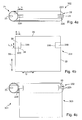
- Fig. 3a to 3c show a winding shaft 202 and a flexible sheet 203 for a roller blind 201 according to a third embodiment of the invention.
- the components essentially correspond to the components according to the Fig. 1a to 1c and common reference numerals are used for like elements.
- slits 220 are introduced into the ends 21, 22 of the winding shaft 202 in the axial direction of the winding shaft 202.
- the slots 220 in the axial direction or axial grooves have a length L_N.
- tabs 230 are formed on the side edges 33 of the flexible sheet 203 at an end edge 34 to be fastened to the winding shaft 202.
- the tabs 230 are through Sections 36 formed in the longitudinal direction L of the flexible sheet 203, the illustrated sections 36 terminate at the end edge 34 of the flexible sheet 203.
- the tabs 230 have a width B_L and a length L_L, wherein the width B_L is substantially equal to a length L_N of the axial slots 220 in FIG Fig. 3a equivalent.
- the tabs 230 are bendable about bending lines 37 running parallel to the transverse direction Q from the flexible sheet 203, wherein the angled tabs 230, as in FIG Fig. 3c shown in the slots 220 are inserted and the flexible sheet 203 for producing the roller blind 201 on the winding shaft 202 according to Fig. 3c is fastened.
- the inserted tabs 230 are glued in the interior of the winding shaft 202 with this, clamped or otherwise connectable with this.
- Fig. 4a to 4c schematically show a winding shaft 302 and a flexible sheet 303 for a roller blind 301 according to a fourth embodiment of the invention.
- the components essentially correspond to the components according to the Fig. 3a to 3c and common reference numerals are used for like elements.
- Fig. 4a and 4c are each formed at the ends 21, 22 two slots 220 in the axial direction, wherein the axial slots 220 each have the length L_N. Through the slots 220 each have a nose 25 is formed at each end 21, 22.
- tabs 330 are formed with length L_L and width B_L.
- the tabs 330 are each formed by a cut 336 in the longitudinal direction L parallel to the lateral edges 33 and at a distance B_L to them.
- 3b coincident planes of the flexible sheet 303 um Crease lines 38 are angled parallel to the transverse direction Q.
- the angled tabs 330 may be used to secure the flexible sheet 303 to the winding shaft 302, as in FIG Fig. 4c shown are pushed into the axial slots 220 under the nose 25.
- an elasticity of the flexible sheet 303 and / or a deformability of the noses 25 can be exploited for attachment to both ends. In other embodiments, such attachment is provided only at one of the ends 21, 22 of the winding shaft 402.
- Fig. 5a and 5b show a winding shaft 402 and the flexible sheet 303 according to Fig. 4b for a roller blind 401 according to a fifth embodiment of the invention.
- the embodiment corresponds essentially to the embodiment according to the Fig. 4a to 4c and common reference numerals are used for like elements.
- a flexible sheet 303 according to Fig. 4b attachable, wherein the tab 330, as in Fig. 5b represented, is interwoven with the lugs 25 of the winding shaft 402.
- the various types of attachment are combined and / or the flexible fabric is woven only at a lateral edge with the winding shaft.
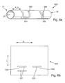
- FIG. 6a shows a winding shaft 502 for a roller blind according to a sixth embodiment of the invention.
- the illustrated winding shaft 502 has a substantially U-shaped recess 520 through which a first nose 521 is formed, and a substantially V-shaped recess 524 through which another nose 525 is formed.
- the illustrated recesses 520, 524 are merely exemplary.
- winding shafts are also conceivable, which have two or more U-shaped recesses 520 and / or two or more V-shaped recesses 524 and / or modifications thereof.
- winding shafts are conceivable, which have only a U- or V-shaped recess, but two or more in the axial direction of the winding shaft spaced-apart recesses are advantageous for a better rotation.
- the recesses 520, 524 can be introduced at an arbitrary distance A_U from the ends 21, 22 of the tubular winding shaft 502.
- FIG. 6b shows a flexible sheet 503 with tabs 530, 534 through which the flexible sheet 503 on the winding shaft 502 according to FIG. 6a is fastened.
- a first tab 530 is formed by two slots 531 extending in the transverse direction Q.
- the nose 521 of the FIG. 6a shown winding shaft 502 can be performed when attaching the flexible sheet 503 to the winding shaft 502 through the slots 531, so that the tab 530 is inserted into the recess 520.
- One edge of the nose 521 comes to lie under the flexible sheet 503. Even with completely unwound fabric the edge is thus not prominent and a risk of injury and / or the risk of damage is thus excluded.
- a tab for the Recess 520 is formed by only one slot 531, wherein the edge of the nose 521 comes to rest over the corresponding region of the flexible sheet. It should be noted that a risk of injury is also minimal here due to the usual arrangement of a winding shaft.
- a tab 534 is in FIG. 6b schematically for connection with the nose 525 according to FIG. 6a shown.
- the tab 534 is formed by only one slot 531 in the transverse direction Q.
- the nose 525 comes to overlie the flexible sheet 503, so that the flexible sheet 503 on the winding shaft 502 according to FIG FIG. 6a is attached.
- FIG. 7 shows an exploded view of an end portion of a winding shaft 602 and a flexible sheet 603 and a bearing bush 604 for a roller blind 601 according to a seventh embodiment of the invention.
- the winding shaft 602 has a recess 624 at its end 621.
- a corner of the flexible sheet 603 is turned over.
- the tab 630, the recess 624 of the winding shaft 602 are introduced and fixed there with the socket 603.
- the recess 624 has an inclined flank whose angle substantially coincides with a bending angle for bending the flap 630.
- the winding shaft 602 has a groove 623, through which the bearing bush 604 when inserted into the end 621 of the winding shaft 602 rotatably connected to the winding shaft 602 is connected.
- the recess 624 directly adjoins the groove 623 in the circumferential direction.
- a spring 640 and a detent 641 are formed, which are inserted into the groove 623 and the recess 624.
- the spring 640 serves the non-rotatable connection of the bearing bush 604 with the winding shaft 602.
- the detent 641 serves to clamp the flexible sheet 603 on the winding shaft 602.
- FIG. 8 shows a portion of a winding shaft 702 and a flexible sheet 703 and a bearing bush 704 of a shade 701 according to an eighth embodiment in an exploded view.
- the flexible sheet 703 has an opening 731 extending in the longitudinal direction L, and the opening 731 is designed essentially as a section in the longitudinal direction L in the exemplary embodiment shown, wherein a rupture is to be prevented by circular widening at the ends of the section.
- the flexible sheet 703 substantially corresponds to the sheet 303 according to FIG Fig. 4b , As in the case of this flat structure 303, a tab 730 can be angled away from the plane of the fabric 703 about bending lines 738 between the aperture 731 and a lateral edge 733 of the flexible fabric 703.
- the tab 730 can be inserted into a complementary recess 724 of the winding shaft 702.
- the bushing 704 provided with a detent 741, which is pushed on insertion of the bushing 704 in the end 721 of the winding shaft 702 via the inserted into the recess 724 tab 730.
- the latching lug 704 and the flexible sheet are "interwoven" with each other. This will do that flexible fabric 703 jammed with the winding shaft 702.
- a groove 723 is provided on the winding shaft 702
- a complementary spring 740 is provided on the bearing bush 704.
- the cuts can be made at their cut ends with transverse slots which prevent tearing of the flexible sheet beyond the cut.
- the cuts can be produced by knives, scissors or the like in tarpaulins or similar fabrics. Furthermore, it is conceivable to provide the "cuts" in woven and / or braided fabrics already during production, wherein the cuts may have corresponding borders which prevent undesired tearing.
Landscapes
- Engineering & Computer Science (AREA)
- Structural Engineering (AREA)
- Architecture (AREA)
- Civil Engineering (AREA)
- Mechanical Engineering (AREA)
- Operating, Guiding And Securing Of Roll- Type Closing Members (AREA)
- Winding Of Webs (AREA)
- Blinds (AREA)
- Storage Of Web-Like Or Filamentary Materials (AREA)
- Controlling Rewinding, Feeding, Winding, Or Abnormalities Of Webs (AREA)
- Perforating, Stamping-Out Or Severing By Means Other Than Cutting (AREA)
- Replacement Of Web Rolls (AREA)
Priority Applications (1)
| Application Number | Priority Date | Filing Date | Title |
|---|---|---|---|
| EP12162481.1A EP2472050B1 (fr) | 2007-03-02 | 2008-02-28 | Procédé de fixation d'une toile flexible sur un arbre d'enroulement et store |
Applications Claiming Priority (1)
| Application Number | Priority Date | Filing Date | Title |
|---|---|---|---|
| DE102007011608A DE102007011608A1 (de) | 2007-03-02 | 2007-03-02 | Verfahren zur Befestigung eines flexiblen Flächengebildes an einer Wickelwelle und Wickelwelle |
Related Child Applications (2)
| Application Number | Title | Priority Date | Filing Date |
|---|---|---|---|
| EP12162481.1A Division-Into EP2472050B1 (fr) | 2007-03-02 | 2008-02-28 | Procédé de fixation d'une toile flexible sur un arbre d'enroulement et store |
| EP12162481.1A Division EP2472050B1 (fr) | 2007-03-02 | 2008-02-28 | Procédé de fixation d'une toile flexible sur un arbre d'enroulement et store |
Publications (3)
| Publication Number | Publication Date |
|---|---|
| EP1965017A2 true EP1965017A2 (fr) | 2008-09-03 |
| EP1965017A3 EP1965017A3 (fr) | 2011-06-08 |
| EP1965017B1 EP1965017B1 (fr) | 2012-09-12 |
Family
ID=39535732
Family Applications (2)
| Application Number | Title | Priority Date | Filing Date |
|---|---|---|---|
| EP08003630A Active EP1965017B1 (fr) | 2007-03-02 | 2008-02-28 | Procédé de fixation d'une structure plate flexible sur un arbre d'enroulement et store |
| EP12162481.1A Active EP2472050B1 (fr) | 2007-03-02 | 2008-02-28 | Procédé de fixation d'une toile flexible sur un arbre d'enroulement et store |
Family Applications After (1)
| Application Number | Title | Priority Date | Filing Date |
|---|---|---|---|
| EP12162481.1A Active EP2472050B1 (fr) | 2007-03-02 | 2008-02-28 | Procédé de fixation d'une toile flexible sur un arbre d'enroulement et store |
Country Status (6)
| Country | Link |
|---|---|
| US (1) | US7909083B2 (fr) |
| EP (2) | EP1965017B1 (fr) |
| JP (1) | JP2008215067A (fr) |
| KR (1) | KR20080080939A (fr) |
| CN (1) | CN101255782A (fr) |
| DE (1) | DE102007011608A1 (fr) |
Cited By (3)
| Publication number | Priority date | Publication date | Assignee | Title |
|---|---|---|---|---|
| WO2011081220A1 (fr) * | 2009-12-29 | 2011-07-07 | Nikon Corporation | Boîtier de substrat et appareil de rangement de substrat |
| CN103522876A (zh) * | 2013-10-26 | 2014-01-22 | 王兆进 | 一种折叠式的汽车遮阳板 |
| WO2015022246A1 (fr) * | 2013-08-16 | 2015-02-19 | Webasto SE | Ensemble de store de véhicule |
Families Citing this family (10)
| Publication number | Priority date | Publication date | Assignee | Title |
|---|---|---|---|---|
| DE102007011608A1 (de) * | 2007-03-02 | 2008-09-04 | Bos Gmbh & Co. Kg | Verfahren zur Befestigung eines flexiblen Flächengebildes an einer Wickelwelle und Wickelwelle |
| CN101676766B (zh) * | 2008-09-16 | 2011-07-27 | 鸿富锦精密工业(深圳)有限公司 | 电子设备屏幕的保护装置 |
| US20110180219A1 (en) * | 2010-01-24 | 2011-07-28 | Nutmeg Industries, Inc., d.b.a. Roll-A-Shade | Replaceable shade system and method of using same |
| TWI553212B (zh) * | 2011-05-25 | 2016-10-11 | Tachikawa Blind Mfg | The manufacture of a roll curtain, a roll closure, a roll curtain, a roll curtain, or a construction method |
| TWM469211U (zh) * | 2013-07-23 | 2014-01-01 | Macauto Ind Co Ltd | 天窗用遮陽裝置 |
| DE102014207408A1 (de) | 2014-04-17 | 2015-10-22 | Bos Gmbh & Co. Kg | Schutzvorrichtung für ein Kraftfahrzeug und Rollowelle hierfür |
| JP6378943B2 (ja) * | 2014-06-18 | 2018-08-22 | 文化シヤッター株式会社 | 開閉装置 |
| CN106401441A (zh) * | 2016-12-22 | 2017-02-15 | 宁波引钲信息咨询有限公司 | 窗帘的卷轴与卷轴座的定位结构 |
| KR102081587B1 (ko) * | 2019-06-26 | 2020-02-26 | 주식회사 나들 | 영역별로 온도 제어가 가능한 발열 블라인드 |
| CN111749502B (zh) * | 2020-06-29 | 2021-07-27 | 大连医科大学附属第一医院 | 一种妇产科用模块化医疗病房隔间 |
Citations (7)
| Publication number | Priority date | Publication date | Assignee | Title |
|---|---|---|---|---|
| US1773786A (en) * | 1928-03-14 | 1930-08-26 | Trofini H Olhow | Vehicle curtain roller |
| FR981666A (fr) * | 1949-01-08 | 1951-05-29 | Perfectionnements aux rouleaux de store automatiques | |
| US4139231A (en) * | 1978-05-08 | 1979-02-13 | Irvin Industries Inc. | Automobile rear compartment cover |
| DE9111226U1 (de) * | 1991-09-10 | 1992-02-06 | Wang, Fore Sheng, Panchio, Taipeh | Sonnenblendrollo für ein Kraftfahrzeug |
| DE19530310A1 (de) * | 1994-10-26 | 1996-05-02 | Mitsubishi Electric Corp | Vorhangwickelvorrichtung |
| EP1447276A2 (fr) * | 2003-02-11 | 2004-08-18 | BOS GmbH & Co. KG | Dispositif d'arbre d'enroulement pour véhicules pour enrouler une bande de matériau |
| US20060207731A1 (en) * | 2004-10-05 | 2006-09-21 | Stephen Lukos | Roller tube having external slot for mounting sheet material |
Family Cites Families (14)
| Publication number | Priority date | Publication date | Assignee | Title |
|---|---|---|---|---|
| US1287135A (en) * | 1916-09-14 | 1918-12-10 | Frank A Swanson | Window-screen. |
| US1459772A (en) * | 1922-05-29 | 1923-06-26 | Charles W Kirsch | Window-shade roller |
| GB223641A (en) * | 1923-07-21 | 1924-10-21 | George Frederick French | Improvements in or relating to roller blinds |
| US1562192A (en) * | 1924-02-18 | 1925-11-17 | Charles E Rowe | Window-shade guide |
| US1734769A (en) * | 1927-06-01 | 1929-11-05 | Donaldson Mfg Company Ltd | Fastening means for securing fabric to a rigid base |
| US1747081A (en) * | 1928-01-19 | 1930-02-11 | Careymcfall Co | Means for securing window shades to metallic rollers |
| US1834669A (en) * | 1930-12-09 | 1931-12-01 | J S Groome | Awning roller |
| US3228455A (en) * | 1963-12-31 | 1966-01-11 | Radiant Mfg Corp | Projection screen |
| US3329195A (en) * | 1965-05-24 | 1967-07-04 | Kinkead Industries | Projection screen or the like |
| US3724524A (en) * | 1971-02-25 | 1973-04-03 | Da Lite Screen Co | Picture screen roller fabric attachment |
| DE2427999A1 (de) * | 1974-06-10 | 1976-01-02 | Sps Stahl Profilier Schneid | Rolladenwelle |
| JPH0617993Y2 (ja) * | 1987-04-30 | 1994-05-11 | 株式会社ニチベイ | ロ−ルブラインドのスクリ−ン取付け構造 |
| US7240875B2 (en) * | 2003-10-14 | 2007-07-10 | Sonoco Development, Inc. | Yarn carrier |
| DE102007011608A1 (de) * | 2007-03-02 | 2008-09-04 | Bos Gmbh & Co. Kg | Verfahren zur Befestigung eines flexiblen Flächengebildes an einer Wickelwelle und Wickelwelle |
-
2007
- 2007-03-02 DE DE102007011608A patent/DE102007011608A1/de not_active Withdrawn
-
2008
- 2008-02-28 EP EP08003630A patent/EP1965017B1/fr active Active
- 2008-02-28 EP EP12162481.1A patent/EP2472050B1/fr active Active
- 2008-02-29 KR KR1020080019034A patent/KR20080080939A/ko not_active Application Discontinuation
- 2008-03-03 US US12/074,315 patent/US7909083B2/en not_active Expired - Fee Related
- 2008-03-03 JP JP2008052184A patent/JP2008215067A/ja active Pending
- 2008-03-03 CN CNA200810082139XA patent/CN101255782A/zh active Pending
Patent Citations (7)
| Publication number | Priority date | Publication date | Assignee | Title |
|---|---|---|---|---|
| US1773786A (en) * | 1928-03-14 | 1930-08-26 | Trofini H Olhow | Vehicle curtain roller |
| FR981666A (fr) * | 1949-01-08 | 1951-05-29 | Perfectionnements aux rouleaux de store automatiques | |
| US4139231A (en) * | 1978-05-08 | 1979-02-13 | Irvin Industries Inc. | Automobile rear compartment cover |
| DE9111226U1 (de) * | 1991-09-10 | 1992-02-06 | Wang, Fore Sheng, Panchio, Taipeh | Sonnenblendrollo für ein Kraftfahrzeug |
| DE19530310A1 (de) * | 1994-10-26 | 1996-05-02 | Mitsubishi Electric Corp | Vorhangwickelvorrichtung |
| EP1447276A2 (fr) * | 2003-02-11 | 2004-08-18 | BOS GmbH & Co. KG | Dispositif d'arbre d'enroulement pour véhicules pour enrouler une bande de matériau |
| US20060207731A1 (en) * | 2004-10-05 | 2006-09-21 | Stephen Lukos | Roller tube having external slot for mounting sheet material |
Cited By (7)
| Publication number | Priority date | Publication date | Assignee | Title |
|---|---|---|---|---|
| WO2011081220A1 (fr) * | 2009-12-29 | 2011-07-07 | Nikon Corporation | Boîtier de substrat et appareil de rangement de substrat |
| CN102712436A (zh) * | 2009-12-29 | 2012-10-03 | 株式会社尼康 | 基板盒及基板收容装置 |
| CN102712436B (zh) * | 2009-12-29 | 2014-12-31 | 株式会社尼康 | 基板盒及基板收容装置 |
| US10541160B2 (en) | 2009-12-29 | 2020-01-21 | Nikon Corporation | Substrate case and substrate accommodation apparatus |
| US11342206B2 (en) | 2009-12-29 | 2022-05-24 | Nikon Corporation | Substrate case and substrate accommodation apparatus |
| WO2015022246A1 (fr) * | 2013-08-16 | 2015-02-19 | Webasto SE | Ensemble de store de véhicule |
| CN103522876A (zh) * | 2013-10-26 | 2014-01-22 | 王兆进 | 一种折叠式的汽车遮阳板 |
Also Published As
| Publication number | Publication date |
|---|---|
| DE102007011608A1 (de) | 2008-09-04 |
| US7909083B2 (en) | 2011-03-22 |
| JP2008215067A (ja) | 2008-09-18 |
| CN101255782A (zh) | 2008-09-03 |
| US20080210389A1 (en) | 2008-09-04 |
| KR20080080939A (ko) | 2008-09-05 |
| EP1965017B1 (fr) | 2012-09-12 |
| EP2472050B1 (fr) | 2015-12-09 |
| EP2472050A2 (fr) | 2012-07-04 |
| EP1965017A3 (fr) | 2011-06-08 |
| EP2472050A3 (fr) | 2013-08-21 |
Similar Documents
| Publication | Publication Date | Title |
|---|---|---|
| EP2472050B1 (fr) | Procédé de fixation d'une toile flexible sur un arbre d'enroulement et store | |
| EP1441933A1 (fr) | Systeme d'essuie-glace pour vitre d'automobile | |
| DE3138445A1 (de) | Federklemme, insbesondere zur befestigung von schmutzfaengern an kraftfahrzeugen | |
| DE10317836A1 (de) | Stabilisatorstangenanordnung für ein Kraftfahrzeug | |
| WO2014056638A1 (fr) | Dispositif de fixation permettant de fixer un système de ventilation à un siège | |
| WO2020200776A1 (fr) | Élément de réglage en plusieurs parties pour un agencement de compensation de tolérances | |
| DE102013217064A1 (de) | Anordnung eines Befestigungselementes an einer Befestigungslasche eines Gassacks und Verfahren zu deren Herstellung | |
| DE102009043269A1 (de) | Radnabe | |
| DE102005017746B4 (de) | Einbauanordnung für Antriebswellen in Kreuzgelenkgabeln | |
| EP2930064B1 (fr) | Caisson de store et système de store | |
| DE102011004049A1 (de) | Vorrichtung zur Anordnung eines Befestigungselementes an einer Befestigungslasche eines Gassacks eines Fahrzeuginsassen-Rückhaltesystems | |
| DE102016120176A1 (de) | Gassackmodul | |
| DE102017110746A1 (de) | Dachrollosystem für ein Kraftahrzeug und Verfahren zur Montage eines Dachrollosystems für ein Kraftfahrzeug | |
| WO2018077715A1 (fr) | Module de coussin gonflable | |
| DE102012007971A1 (de) | Halteclip in einem Kraftfahrzeug | |
| DE102010020444B4 (de) | Aufblasbare Airbageinheit | |
| DE202007008184U1 (de) | Rolo mit einem daran befestigten flexiblen Flächengebilde | |
| DE3000759C2 (fr) | ||
| DE102006059096A1 (de) | Baugruppe zur fahrzeugseitigen Befestigung eines Gurtschlosses | |
| DE102012009911B4 (de) | Sicherheitsgurteinrichtung für ein Fahrzeug und Dämpfungsmittel für eine solche Sicherheitsgurteinrichtung | |
| EP2369184A2 (fr) | Dispositif doté d'un équilibrage automatique des tolérances déterminées par la fabrication ou le montage et destiné au support d'un premier composant sur un second composant | |
| DE8125330U1 (de) | Sonnenblende fuer kraftfahrzeuge od.dgl. | |
| DE102017110747B4 (de) | Federkassette für ein Dachrollosystem eines Kraftfahrzeugs und Baugruppe für ein Dachrollosystem eines Kraftfahrzeugs | |
| DE2413982A1 (de) | Sicherung fuer bolzen, wellen, zapfen oder dergleichen | |
| DE102007011414A1 (de) | Für ein bogenförmiges Fenster geeignete Sonnenblende |
Legal Events
| Date | Code | Title | Description |
|---|---|---|---|
| PUAI | Public reference made under article 153(3) epc to a published international application that has entered the european phase |
Free format text: ORIGINAL CODE: 0009012 |
|
| AK | Designated contracting states |
Kind code of ref document: A2 Designated state(s): AT BE BG CH CY CZ DE DK EE ES FI FR GB GR HR HU IE IS IT LI LT LU LV MC MT NL NO PL PT RO SE SI SK TR |
|
| AX | Request for extension of the european patent |
Extension state: AL BA MK RS |
|
| PUAL | Search report despatched |
Free format text: ORIGINAL CODE: 0009013 |
|
| AK | Designated contracting states |
Kind code of ref document: A3 Designated state(s): AT BE BG CH CY CZ DE DK EE ES FI FR GB GR HR HU IE IS IT LI LT LU LV MC MT NL NO PL PT RO SE SI SK TR |
|
| AX | Request for extension of the european patent |
Extension state: AL BA MK RS |
|
| RIC1 | Information provided on ipc code assigned before grant |
Ipc: B60J 1/20 20060101ALI20110429BHEP Ipc: E06B 9/44 20060101AFI20080702BHEP |
|
| 17P | Request for examination filed |
Effective date: 20111129 |
|
| AKX | Designation fees paid |
Designated state(s): DE FR SE |
|
| GRAP | Despatch of communication of intention to grant a patent |
Free format text: ORIGINAL CODE: EPIDOSNIGR1 |
|
| RIC1 | Information provided on ipc code assigned before grant |
Ipc: E06B 9/44 20060101AFI20120323BHEP Ipc: B60J 1/20 20060101ALI20120323BHEP |
|
| GRAS | Grant fee paid |
Free format text: ORIGINAL CODE: EPIDOSNIGR3 |
|
| GRAA | (expected) grant |
Free format text: ORIGINAL CODE: 0009210 |
|
| AK | Designated contracting states |
Kind code of ref document: B1 Designated state(s): DE FR SE |
|
| REG | Reference to a national code |
Ref country code: DE Ref legal event code: R096 Ref document number: 502008008125 Country of ref document: DE Effective date: 20121108 |
|
| PG25 | Lapsed in a contracting state [announced via postgrant information from national office to epo] |
Ref country code: SE Free format text: LAPSE BECAUSE OF FAILURE TO SUBMIT A TRANSLATION OF THE DESCRIPTION OR TO PAY THE FEE WITHIN THE PRESCRIBED TIME-LIMIT Effective date: 20120912 |
|
| PLBE | No opposition filed within time limit |
Free format text: ORIGINAL CODE: 0009261 |
|
| STAA | Information on the status of an ep patent application or granted ep patent |
Free format text: STATUS: NO OPPOSITION FILED WITHIN TIME LIMIT |
|
| 26N | No opposition filed |
Effective date: 20130613 |
|
| REG | Reference to a national code |
Ref country code: DE Ref legal event code: R097 Ref document number: 502008008125 Country of ref document: DE Effective date: 20130613 |
|
| REG | Reference to a national code |
Ref country code: FR Ref legal event code: PLFP Year of fee payment: 9 |
|
| REG | Reference to a national code |
Ref country code: FR Ref legal event code: PLFP Year of fee payment: 10 |
|
| REG | Reference to a national code |
Ref country code: FR Ref legal event code: PLFP Year of fee payment: 11 |
|
| PGFP | Annual fee paid to national office [announced via postgrant information from national office to epo] |
Ref country code: FR Payment date: 20190221 Year of fee payment: 12 |
|
| PG25 | Lapsed in a contracting state [announced via postgrant information from national office to epo] |
Ref country code: FR Free format text: LAPSE BECAUSE OF NON-PAYMENT OF DUE FEES Effective date: 20200229 |
|
| PGFP | Annual fee paid to national office [announced via postgrant information from national office to epo] |
Ref country code: DE Payment date: 20240226 Year of fee payment: 17 |