EP1961283B1 - Appareil de traitement de sols - Google Patents
Appareil de traitement de sols Download PDFInfo
- Publication number
- EP1961283B1 EP1961283B1 EP07113238A EP07113238A EP1961283B1 EP 1961283 B1 EP1961283 B1 EP 1961283B1 EP 07113238 A EP07113238 A EP 07113238A EP 07113238 A EP07113238 A EP 07113238A EP 1961283 B1 EP1961283 B1 EP 1961283B1
- Authority
- EP
- European Patent Office
- Prior art keywords
- soil cultivation
- cultivation device
- supporting frame
- hydraulic cylinder
- adjusting
- Prior art date
- Legal status (The legal status is an assumption and is not a legal conclusion. Google has not performed a legal analysis and makes no representation as to the accuracy of the status listed.)
- Active
Links
- 239000002689 soil Substances 0.000 title claims description 19
- 238000006073 displacement reaction Methods 0.000 claims description 4
- 244000126211 Hericium coralloides Species 0.000 abstract 2
- 235000021438 curry Nutrition 0.000 abstract 2
- 238000003971 tillage Methods 0.000 description 8
- 238000003754 machining Methods 0.000 description 2
- 241000196324 Embryophyta Species 0.000 description 1
- 239000002131 composite material Substances 0.000 description 1
- 230000001419 dependent effect Effects 0.000 description 1
- 238000011161 development Methods 0.000 description 1
- 230000018109 developmental process Effects 0.000 description 1
- 239000003999 initiator Substances 0.000 description 1
Images


Classifications
-
- A—HUMAN NECESSITIES
- A01—AGRICULTURE; FORESTRY; ANIMAL HUSBANDRY; HUNTING; TRAPPING; FISHING
- A01B—SOIL WORKING IN AGRICULTURE OR FORESTRY; PARTS, DETAILS, OR ACCESSORIES OF AGRICULTURAL MACHINES OR IMPLEMENTS, IN GENERAL
- A01B39/00—Other machines specially adapted for working soil on which crops are growing
- A01B39/20—Tools; Details
- A01B39/22—Tools; Mounting tools
-
- A—HUMAN NECESSITIES
- A01—AGRICULTURE; FORESTRY; ANIMAL HUSBANDRY; HUNTING; TRAPPING; FISHING
- A01B—SOIL WORKING IN AGRICULTURE OR FORESTRY; PARTS, DETAILS, OR ACCESSORIES OF AGRICULTURAL MACHINES OR IMPLEMENTS, IN GENERAL
- A01B19/00—Harrows with non-rotating tools
- A01B19/02—Harrows with non-rotating tools with tools rigidly or elastically attached to a tool-frame
-
- A—HUMAN NECESSITIES
- A01—AGRICULTURE; FORESTRY; ANIMAL HUSBANDRY; HUNTING; TRAPPING; FISHING
- A01B—SOIL WORKING IN AGRICULTURE OR FORESTRY; PARTS, DETAILS, OR ACCESSORIES OF AGRICULTURAL MACHINES OR IMPLEMENTS, IN GENERAL
- A01B63/00—Lifting or adjusting devices or arrangements for agricultural machines or implements
- A01B63/002—Devices for adjusting or regulating the position of tools or wheels
- A01B63/008—Vertical adjustment of tools
-
- A—HUMAN NECESSITIES
- A01—AGRICULTURE; FORESTRY; ANIMAL HUSBANDRY; HUNTING; TRAPPING; FISHING
- A01B—SOIL WORKING IN AGRICULTURE OR FORESTRY; PARTS, DETAILS, OR ACCESSORIES OF AGRICULTURAL MACHINES OR IMPLEMENTS, IN GENERAL
- A01B63/00—Lifting or adjusting devices or arrangements for agricultural machines or implements
- A01B63/14—Lifting or adjusting devices or arrangements for agricultural machines or implements for implements drawn by animals or tractors
- A01B63/24—Tools or tool-holders adjustable relatively to the frame
-
- A—HUMAN NECESSITIES
- A01—AGRICULTURE; FORESTRY; ANIMAL HUSBANDRY; HUNTING; TRAPPING; FISHING
- A01B—SOIL WORKING IN AGRICULTURE OR FORESTRY; PARTS, DETAILS, OR ACCESSORIES OF AGRICULTURAL MACHINES OR IMPLEMENTS, IN GENERAL
- A01B71/00—Construction or arrangement of setting or adjusting mechanisms, of implement or tool drive or of power take-off; Means for protecting parts against dust, or the like; Adapting machine elements to or for agricultural purposes
- A01B71/02—Setting or adjusting mechanisms
Definitions
- the invention relates to a soil cultivation device, in particular for the care of soil surfaces between crops, according to the preamble of claim 1.
- Such a harrow is from the DE 201 15 048 known.
- This has a plurality on a support frame pivotally arranged harrow tines, which are biased by a respective spring.
- the springs are connected on the one hand to the respective harrow tines and on the other hand via a pull cable with a control element arranged on the support element.
- On the adjusting element five different mounting options for the tension cables connected to the springs are provided, so that the bias of the springs and thus the bias of the harrow tines can be adjusted centrally by changing the position of the attachment points of the traction ropes.
- a disadvantage of this tillage device with manual adjustment of the bias is that the processing must be interrupted for adjustment.
- the soil condition can constantly change during tillage and the machining process must be stopped before each adjustment, a change in the bias of the harrow tines is associated with a considerable amount of time.
- the object of the invention is to provide a harrow of the type mentioned, which allows a quick and easy change in the bias of the harrow tines even during tillage.
- the adjusting device is associated with an electric or hydraulic actuator that can be controlled by means of a control device.
- the central change in the bias of the harrow tines or the setting of the tine pressure can thus, for example, from the towing vehicle also during processing respectively. If necessary, the tine pressure can be easily and quickly adapted to the respective soil conditions, for which purpose the machining process does not have to be interrupted.
- the farmer can, for example, specify the desired tine pressure on the electronic control unit, which can then also be displayed and monitored via a corresponding display device.
- An electric actuator may conveniently comprise a geared motor mounted on the support frame, e.g. is coupled via a belt or chain drive with at least one thumbwheel for rotation of at least one connected to the springs via pull cables drive shaft.
- a with respect to the energy supply particularly advantageous and therefore for driving large tillage equipment with many harrow tines perfectly suitable hydraulic drive may comprise a arranged on the support frame hydraulic cylinder which is coupled via a Switzerlandstoffan für lovatose cylinder which is coupled via a Switzerlandstoffan für lovatose cylinder and at least one thumbwheel for rotation of at least one connected to the springs via pull cables drive shaft ,
- the tillage implement shown in a side view is a so-called tine harrow, which is used in agricultural agriculture for soil cultivation. and Seeds cultivation of crops, especially for weed control in organic crops, is used. It contains several arranged on a support frame 1 harrow tines 2, which are biased by a respective spring 3 against a stop 4.
- the support frame 1 has at its in FIG. 1 right end to a three-point block 5, via which the support frame 1 can be attached to a towing vehicle.
- the support frame 1 includes a plurality of spaced-apart longitudinal members 6 and cross struts 8, on which the angled at the bottom in the direction of harrow harrow tines 2 are articulated in the longitudinal and transverse directions spaced from each other.
- one end of the springs 3 is attached to the harrow tine 2 below its articulation, while the other end of the springs 3 is connected via a respective traction cable 7 with a rotatably mounted on the support frame 1 adjusting shaft 9.
- a central adjustment of the tine pressure of the harrow tines 2 can be achieved.
- the control of the geared motor 13 via a mounted in towing vehicle control unit 14 which is provided with a monitor or other electronic display device 15.
- an initiator or sensor 16 is arranged, by means of which the angular position of the setting wheel 10 can be detected by means of several evenly distributed on the drive wheel over its circumference holes 17 and a reference zero point 18. Thereby, the selected bias can be determined and displayed on the electronic display device 15 of the controller 14.
- FIG. 2 is a part of another tine harrow with a hydraulic actuator shown schematically.
- the articulated to the cross struts 8 harrow tines 2 are biased by a spring 3 against a stop 4.
- the one end of the spring 3 is also fixed to the harrow tines 2, while the other end of the spring 3 is connected via a pull cable 7 with an adjusting shaft 9 rotatably mounted on the support frame 1.
- a thumbwheel 10 is provided, which is here, however, coupled via a designed as a cable Ceizieranssen with the piston 19 of a hydraulic cylinder 20.
- the Switzerlandstoffanssen includes a guided over pulleys 21 rope 22, whose one end to the piston 19 of the hydraulic cylinder 20 and the other end with the adjusting wheel 10 is connected. By displacement of the piston 19 so the thumbwheel 10 is rotated and thus the bias of the harrow tines 2 are changed.
- the actuation of the hydraulic cylinder 20 via a designed as a 2/2-way valve hydraulic control valve 23 which is arranged on the support frame 1 and via a supply or return line 24 and 25 with a supply unit on the towing vehicle can be connected.
- a connecting line 26 to the control unit 14 the control valve 23 can be controlled from the towing vehicle.
- a linear measuring system 27 is further attached, which is connected via a line 28 to the control unit 14. With the help of the linear measuring system 27, the displacement of the piston 19 and thus the adjustment of the bias of the harrow tines 2 detected and displayed via the line 28 to the electronic display device 15 of the controller 14.
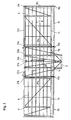
- FIG. 3 shows in a plan view of a three-piece tine harrow, which is equipped with a hydraulic actuator described above.
- the support frame 1 of this tine harrow consists of three composite lattice-like parts 1a, 1b and 1c, of which the middle part 1a contains the three-point block 5 provided for attachment to the towing vehicle.
- the two outer parts 1b and 1c of the support frame 1 are hinged upwardly on the central part 1a.
- the different parts 1a, 1b and 1c also have three separate adjustment shafts 9a, 9b and 9c with separate setting wheels 10a, 10b and 10c.
- the adjusting wheels 10a, 10b and 10c are respectively to the in FIG. 3 attached to right ends of the adjusting shafts 9a, 9b and 9c.
- the harrow tines are mounted laterally offset by 28 mm to each other.
- springs 3 and corresponding traction cables 7, these are connected to the adjusting shafts 9a, 9b and 9c for simultaneous adjustment.
- the piston rod 19 of the hydraulic cylinder 20 fastened to the middle part 1a of the support frame 1 is connected to the setting wheel 10a by a first cable 22a guided via first deflection rollers 21a. From the piston rod 19 also performs a second cable 22b via second pulleys 21b to the setting wheel 10b.
- This Switzerlandstoffanssenanssen of several According to deflected ropes 22a to 22c so all arranged on the different parts 1a, 1b and 1c of the support frame 1 harrow tines 2 can be adjusted by the hydraulic cylinder 20 centrally.
- additional turnbuckles 29a, 29b and 29c are arranged in the embodiment shown. Through this, if necessary, a fine adjustment of the different parts can be made.
- FIG. 4 may be attached to the hydraulic cylinder 20 and a mechanical display device for displaying the selected biasing position.
- a pointer 30 which cooperates with a fixed frame on the support frame 31.
- this mechanical display device can be monitored by the hydraulic cylinder 20 preselected bias of harrow tines 2.
- the invention is not limited to the embodiment described above.
- the in FIG. 3 three-piece executed support frame also be made in one piece or have more parts depending on the desired width.
- tine harrows are offered with one, three or five parts at working widths of 1.7 to 12.2 meters.
Landscapes
- Life Sciences & Earth Sciences (AREA)
- Engineering & Computer Science (AREA)
- Mechanical Engineering (AREA)
- Soil Sciences (AREA)
- Environmental Sciences (AREA)
- Zoology (AREA)
- Soil Working Implements (AREA)
Claims (11)
- Appareil de traitement des sols, en particulier pour l'entretien des surfaces de sol de plantations de cultures, avec un châssis porteur (1), plusieurs dents de herse étrille (2) disposées de manière pivotante au niveau du châssis porteur (1) et un dispositif de réglage (9, 10) affecté aux dents de herse étrille (2) par lequel la précontrainte des dents de herse étrille (2) précontraintes par le biais de ressorts (3) est réglable centralement, caractérisé en ce qu'un servomoteur électrique ou hydraulique (11, 13 ; 20, 22) pouvant être commandé au moyen d'un appareil de commande (14) est affecté au dispositif de réglage (9, 10).
- Appareil de traitement des sols selon la revendication 1, caractérisé en ce que le servomoteur électrique (11, 13) comprend un moto-réducteur (13) disposé au niveau du châssis porteur (1) et couplé à une roue de réglage (10) pour la mise en rotation d'au moins un arbre d'entraînement (9) relié aux ressorts (3) par le biais de câbles de traction (7).
- Appareil de traitement des sols selon la revendication 2, caractérisé en ce que le moto-réducteur (13) est couplé à la roue de réglage (10) par le biais d'un entraînement par chaîne ou courroie (11).
- Appareil de traitement des sols selon la revendication 2 ou 3, caractérisé en ce qu'un capteur (16) est disposé au niveau du châssis porteur (1) pour la détection de la position angulaire de la roue de réglage (10).
- Appareil de traitement des sols selon la revendication 1, caractérisé en ce que le servomoteur hydraulique (9, 20) comprend un vérin hydraulique (20) disposé au niveau du châssis porteur (1), dont la tige de piston (19) est couplée, par au moins un câble (22) guidé via des poulies de renvoi (21), à au moins une roue de réglage (9) pour la mise en rotation d'au moins un arbre d'entraînement (9) relié aux ressorts (3) par le biais de câbles de traction (7).
- Appareil de traitement des sols selon la revendication 5, caractérisé en ce qu'un système de mesure linéaire (20) est disposé au niveau du vérin hydraulique (20) pour la détection du déport d'une tige de piston (19) du vérin hydraulique (20).
- Appareil de traitement des sols selon la revendication 5 ou 6, caractérisé en ce qu'un dispositif d'affichage mécanique (30, 31) est monté au niveau du vérin hydraulique (20) pour l'affichage du déport de la tige de piston (19) du vérin hydraulique (20).
- Appareil de traitement des sols selon l'une quelconque des revendications 5 à 7, caractérisé en ce qu'une valve de commande hydraulique (23) est disposée au niveau du châssis porteur (1) pour l'actionnement du vérin hydraulique (20).
- Appareil de traitement des sols selon l'une quelconque des revendications 5 à 8, caractérisé en ce que la tige de piston (19) du vérin hydraulique (20) est couplée par plusieurs câbles (22a, 22b, 22c) reliés les uns aux autres et guidés via des poulies de renvoi (21a, 21b, 21c) à plusieurs roues de réglage (10a, 10b, 10c) pour la mise en rotation de plusieurs arbres d'entraînement (9a, 9b, 9c) reliés aux ressorts (3) par le biais de câbles de traction (7).
- Appareil de traitement des sols selon la revendication 9, caractérisé en ce que des tendeurs (29a, 29b, 29c) sont disposés dans les câbles (22a, 22b, 22c).
- Appareil de traitement des sols selon l'une quelconque des revendications 1 à 10, caractérisé en ce que le châssis porteur (1) est composé de plusieurs parties (1a, 1b, 1c).
Applications Claiming Priority (1)
| Application Number | Priority Date | Filing Date | Title |
|---|---|---|---|
| DE102007008616A DE102007008616A1 (de) | 2007-02-22 | 2007-02-22 | Elektronische Zinkendruckverstelleinheit |
Publications (3)
| Publication Number | Publication Date |
|---|---|
| EP1961283A1 EP1961283A1 (fr) | 2008-08-27 |
| EP1961283B1 true EP1961283B1 (fr) | 2011-09-14 |
| EP1961283B2 EP1961283B2 (fr) | 2017-01-04 |
Family
ID=39431080
Family Applications (1)
| Application Number | Title | Priority Date | Filing Date |
|---|---|---|---|
| EP07113238.5A Active EP1961283B2 (fr) | 2007-02-22 | 2007-07-26 | Appareil de traitement des sols |
Country Status (3)
| Country | Link |
|---|---|
| EP (1) | EP1961283B2 (fr) |
| AT (1) | ATE524059T1 (fr) |
| DE (1) | DE102007008616A1 (fr) |
Cited By (4)
| Publication number | Priority date | Publication date | Assignee | Title |
|---|---|---|---|---|
| EP3245855A1 (fr) | 2016-04-28 | 2017-11-22 | Horsch Maschinen GmbH | Cultivateur, dents plates associées et système de dents plates |
| EP3738419A1 (fr) | 2019-05-16 | 2020-11-18 | Thomas Hatzenbichler Agro-Technik GmbH | Équipement de préparation du sol |
| EP3756432A1 (fr) | 2019-06-27 | 2020-12-30 | Thomas Hatzenbichler Agro-Technik GmbH | Procédé et dispositif pour herses par dents |
| EP4104655A1 (fr) * | 2021-06-16 | 2022-12-21 | Treffler Maschinenbau GmbH & Co. KG | Appareil de traitement du sol |
Families Citing this family (22)
| Publication number | Priority date | Publication date | Assignee | Title |
|---|---|---|---|---|
| DE202010011146U1 (de) * | 2010-08-06 | 2011-11-23 | Paul Treffler | Bodenbearbeitungsgerät |
| RU2455810C2 (ru) * | 2010-10-15 | 2012-07-20 | Федеральное государственное образовательное учреждение высшего профессионального образования Волгоградская государственная сельскохозяйственная академия | Борона пружинная |
| DE102012101641A1 (de) * | 2012-02-29 | 2013-08-29 | Kverneland Asa | Striegeleinrichtung für eine landwirtschaftliche Bodenbearbeitungsvorrichtung |
| DE202012004337U1 (de) * | 2012-04-28 | 2013-07-30 | Paul Treffler | Zinkenstriegel |
| CZ306930B6 (cs) * | 2016-04-01 | 2017-09-20 | Farmet A.S. | Mechanismus pro nastavení přítlaku |
| US10342171B2 (en) | 2016-10-19 | 2019-07-09 | Cnh Industrial America Llc | System for adjusting smoothing tools of a harrow using a linear actuator |
| US10368471B2 (en) | 2016-10-28 | 2019-08-06 | Cnh Industrial America Llc | System for equalizing pressure on smoothing tools of a harrow |
| US10251328B2 (en) | 2016-11-18 | 2019-04-09 | Cnh Industrial America Llc | Electronic sensor assembly for monitoring smoothing tools of a harrow |
| DE102016124517A1 (de) * | 2016-12-15 | 2018-06-21 | Treffler Maschinenbau Gmbh & Co. Kg | Zinkenstriegel-Eindringtiefenmessvorrichtung, Zinkenstriegel sowie Eindringtiefenreguliervorrichtung |
| AT15980U1 (de) * | 2017-04-18 | 2018-10-15 | Juergen Schoels | Bodenbearbeitungsgerät |
| DE102017110637B4 (de) | 2017-05-16 | 2024-05-08 | Treffler Maschinenbau Gmbh & Co. Kg | Vollautomatischer Zinkenstriegel |
| NL1042892B1 (nl) * | 2018-06-06 | 2019-12-11 | Machf Steketee Bv | Wiedmachine en wiedelement |
| DE102019116518A1 (de) | 2019-06-18 | 2020-12-24 | Horsch Maschinen Gmbh | Vorspanneinrichtung und Vorrichtung zur landwirtschaftlichen Bodenbearbeitung |
| DE102019209330A1 (de) * | 2019-06-27 | 2020-12-31 | Einböck GmbH & CoKG | Hackstriegel |
| DE102020111400A1 (de) | 2020-04-27 | 2021-10-28 | Horsch Maschinen Gmbh | Bodenbearbeitungsmaschine, vorzugsweise landwirtschaftlicher hackstriegel und verfahren zum einstellen einer vorspannkraft an einem hackstriegel |
| AT524909B1 (de) * | 2021-03-23 | 2023-02-15 | Dick Bernhard | Ackerstriegel |
| DE102021108388A1 (de) | 2021-04-01 | 2022-10-06 | Horsch Maschinen Gmbh | Bodenbearbeitungsvorrichtung |
| FR3128850B1 (fr) | 2021-11-08 | 2024-05-10 | Ferrand | Instrument aratoire à dents réglables |
| DE102022113134A1 (de) | 2022-05-24 | 2023-11-30 | Eto Magnetic Gmbh | Eggenvorrichtung, Egge, Landmaschine und Verfahren zum Betrieb der Eggenvorrichtung |
| DE102022114253A1 (de) | 2022-06-07 | 2023-12-07 | Horsch Maschinen Gmbh | Landwirtschaftlicher Hackstriegel |
| DE102022114983A1 (de) | 2022-06-14 | 2023-12-14 | Lemken Gmbh & Co. Kg | Landwirtschaftliches Arbeitsgerät |
| FR3141838A1 (fr) * | 2022-11-10 | 2024-05-17 | Ferrand | Instrument aratoire |
Family Cites Families (7)
| Publication number | Priority date | Publication date | Assignee | Title |
|---|---|---|---|---|
| US2727609A (en) * | 1952-02-05 | 1955-12-20 | Jimmie T Kanemoto | Electric trip pull devices for farm machines |
| GB919220A (en) * | 1960-10-14 | 1963-02-20 | Massey Ferguson Australia Ltd | Improvements in or relating to cultivators |
| FR1524258A (fr) * | 1966-04-02 | 1968-05-10 | Rabewerk Clausing Heinrich | étrille agricole, en particulier pour arracher les mauvaises herbes |
| DE3900100A1 (de) * | 1989-01-04 | 1990-07-05 | Josef Niedermaier | Egge |
| DE19839880A1 (de) * | 1998-09-02 | 2000-03-09 | Amazonen Werke Dreyer H | Strohstriegel |
| SE518524C2 (sv) * | 2000-12-21 | 2002-10-22 | Vaederstad Verken Ab | Regleranordning för en jordbruksmaskin |
| DE20115048U1 (de) * | 2001-09-12 | 2001-11-29 | Treffler, Paul, 86554 Pöttmes | Bodenbearbeitungsgerät |
-
2007
- 2007-02-22 DE DE102007008616A patent/DE102007008616A1/de not_active Withdrawn
- 2007-07-26 EP EP07113238.5A patent/EP1961283B2/fr active Active
- 2007-07-26 AT AT07113238T patent/ATE524059T1/de active
Cited By (4)
| Publication number | Priority date | Publication date | Assignee | Title |
|---|---|---|---|---|
| EP3245855A1 (fr) | 2016-04-28 | 2017-11-22 | Horsch Maschinen GmbH | Cultivateur, dents plates associées et système de dents plates |
| EP3738419A1 (fr) | 2019-05-16 | 2020-11-18 | Thomas Hatzenbichler Agro-Technik GmbH | Équipement de préparation du sol |
| EP3756432A1 (fr) | 2019-06-27 | 2020-12-30 | Thomas Hatzenbichler Agro-Technik GmbH | Procédé et dispositif pour herses par dents |
| EP4104655A1 (fr) * | 2021-06-16 | 2022-12-21 | Treffler Maschinenbau GmbH & Co. KG | Appareil de traitement du sol |
Also Published As
| Publication number | Publication date |
|---|---|
| ATE524059T1 (de) | 2011-09-15 |
| EP1961283A1 (fr) | 2008-08-27 |
| DE102007008616A1 (de) | 2008-08-28 |
| EP1961283B2 (fr) | 2017-01-04 |
Similar Documents
| Publication | Publication Date | Title |
|---|---|---|
| EP1961283B1 (fr) | Appareil de traitement de sols | |
| EP3903549B1 (fr) | Machine de traitement du sol, de préférence herse-étrille agricole et procédé de réglage d'une force de précontrainte sur une herse-étrille | |
| EP2656708B1 (fr) | Herse à pointes | |
| EP3434085B1 (fr) | Procédé de réglage d'une ligne de traction | |
| EP1832153A1 (fr) | Semoir | |
| DE102019121322A1 (de) | Hackvorrichtung | |
| EP3152990B1 (fr) | Appareil de travail du sol | |
| DE202015007529U1 (de) | Selbstfahrendes Nutzflächen-Bearbeitungsgerät | |
| EP3106024A1 (fr) | Presse à balles rondes avec des moyens pour le guidage d'une courroie de presse | |
| EP4066608A1 (fr) | Dispositif de traitement du sol | |
| DE102016110810A1 (de) | Einachsgeräteträger und Anbaugerät für einen Einachsgeräteträger | |
| EP3912444A1 (fr) | Dispositif de montage pour appareils de travail agricoles | |
| EP3251481B1 (fr) | Porte-outils mono-axe et appareil porté pour un porte-outils mono-axe | |
| DE102004018591B4 (de) | Bodenbearbeitungsgerät mit Winkelverstellung | |
| DE60007251T2 (de) | Landwirtschaftliche maschine | |
| EP2415336A1 (fr) | Appareil de traitement des sols | |
| DE2108222C3 (de) | Unterlenker-Impulsgeberanordnung für die Regelhydraulik von landwirtschaftlichen Fahrzeugen, wie Schlepper, Geräteträger o.dgl | |
| DE3615818A1 (de) | Verteilmaschine | |
| EP4074157A1 (fr) | Machine agricole pourvue d'au moins un bras | |
| DE2855544C2 (de) | Unterlenkermeßwertgeber zum Regeln der Arbeitstiefe eines an einem Dreipumpgestänge angelenkten Bodenbearbeitungsgerätes, insbesondere eines Pfluges | |
| DE102022114253A1 (de) | Landwirtschaftlicher Hackstriegel | |
| DE102022118611A1 (de) | Landwirtschaftliche Maschine | |
| DE102022118612A1 (de) | Landwirtschaftliche Maschine | |
| DE2814133B1 (de) | Mit einem Anbaurahmen versehene Saeeinrichtung | |
| DE29912417U1 (de) | Landschaftspflegegerät |
Legal Events
| Date | Code | Title | Description |
|---|---|---|---|
| PUAI | Public reference made under article 153(3) epc to a published international application that has entered the european phase |
Free format text: ORIGINAL CODE: 0009012 |
|
| AK | Designated contracting states |
Kind code of ref document: A1 Designated state(s): AT BE BG CH CY CZ DE DK EE ES FI FR GB GR HU IE IS IT LI LT LU LV MC MT NL PL PT RO SE SI SK TR |
|
| AX | Request for extension of the european patent |
Extension state: AL BA HR MK RS |
|
| 17P | Request for examination filed |
Effective date: 20090227 |
|
| AKX | Designation fees paid |
Designated state(s): AT BE BG CH CY CZ DE DK EE ES FI FR GB GR HU IE IS IT LI LT LU LV MC MT NL PL PT RO SE SI SK TR |
|
| AXX | Extension fees paid |
Extension state: RS Payment date: 20090227 Extension state: MK Payment date: 20090227 Extension state: HR Payment date: 20090227 Extension state: BA Payment date: 20090227 |
|
| GRAP | Despatch of communication of intention to grant a patent |
Free format text: ORIGINAL CODE: EPIDOSNIGR1 |
|
| GRAS | Grant fee paid |
Free format text: ORIGINAL CODE: EPIDOSNIGR3 |
|
| GRAA | (expected) grant |
Free format text: ORIGINAL CODE: 0009210 |
|
| AK | Designated contracting states |
Kind code of ref document: B1 Designated state(s): AT BE BG CH CY CZ DE DK EE ES FI FR GB GR HU IE IS IT LI LT LU LV MC MT NL PL PT RO SE SI SK TR |
|
| AX | Request for extension of the european patent |
Extension state: BA HR MK RS |
|
| REG | Reference to a national code |
Ref country code: GB Ref legal event code: FG4D Free format text: NOT ENGLISH |
|
| REG | Reference to a national code |
Ref country code: CH Ref legal event code: EP |
|
| REG | Reference to a national code |
Ref country code: IE Ref legal event code: FG4D Free format text: LANGUAGE OF EP DOCUMENT: GERMAN |
|
| REG | Reference to a national code |
Ref country code: SE Ref legal event code: TRGR |
|
| REG | Reference to a national code |
Ref country code: DE Ref legal event code: R096 Ref document number: 502007008143 Country of ref document: DE Effective date: 20111201 |
|
| REG | Reference to a national code |
Ref country code: NL Ref legal event code: T3 |
|
| REG | Reference to a national code |
Ref country code: CH Ref legal event code: NV Representative=s name: LUCHS & PARTNER PATENTANWAELTE |
|
| PG25 | Lapsed in a contracting state [announced via postgrant information from national office to epo] |
Ref country code: FI Free format text: LAPSE BECAUSE OF FAILURE TO SUBMIT A TRANSLATION OF THE DESCRIPTION OR TO PAY THE FEE WITHIN THE PRESCRIBED TIME-LIMIT Effective date: 20110914 Ref country code: LT Free format text: LAPSE BECAUSE OF FAILURE TO SUBMIT A TRANSLATION OF THE DESCRIPTION OR TO PAY THE FEE WITHIN THE PRESCRIBED TIME-LIMIT Effective date: 20110914 |
|
| LTIE | Lt: invalidation of european patent or patent extension |
Effective date: 20110914 |
|
| PG25 | Lapsed in a contracting state [announced via postgrant information from national office to epo] |
Ref country code: SI Free format text: LAPSE BECAUSE OF FAILURE TO SUBMIT A TRANSLATION OF THE DESCRIPTION OR TO PAY THE FEE WITHIN THE PRESCRIBED TIME-LIMIT Effective date: 20110914 Ref country code: LV Free format text: LAPSE BECAUSE OF FAILURE TO SUBMIT A TRANSLATION OF THE DESCRIPTION OR TO PAY THE FEE WITHIN THE PRESCRIBED TIME-LIMIT Effective date: 20110914 Ref country code: GR Free format text: LAPSE BECAUSE OF FAILURE TO SUBMIT A TRANSLATION OF THE DESCRIPTION OR TO PAY THE FEE WITHIN THE PRESCRIBED TIME-LIMIT Effective date: 20111215 Ref country code: CY Free format text: LAPSE BECAUSE OF FAILURE TO SUBMIT A TRANSLATION OF THE DESCRIPTION OR TO PAY THE FEE WITHIN THE PRESCRIBED TIME-LIMIT Effective date: 20110914 |
|
| REG | Reference to a national code |
Ref country code: IE Ref legal event code: FD4D |
|
| PG25 | Lapsed in a contracting state [announced via postgrant information from national office to epo] |
Ref country code: SK Free format text: LAPSE BECAUSE OF FAILURE TO SUBMIT A TRANSLATION OF THE DESCRIPTION OR TO PAY THE FEE WITHIN THE PRESCRIBED TIME-LIMIT Effective date: 20110914 Ref country code: CZ Free format text: LAPSE BECAUSE OF FAILURE TO SUBMIT A TRANSLATION OF THE DESCRIPTION OR TO PAY THE FEE WITHIN THE PRESCRIBED TIME-LIMIT Effective date: 20110914 Ref country code: IE Free format text: LAPSE BECAUSE OF FAILURE TO SUBMIT A TRANSLATION OF THE DESCRIPTION OR TO PAY THE FEE WITHIN THE PRESCRIBED TIME-LIMIT Effective date: 20110914 Ref country code: IS Free format text: LAPSE BECAUSE OF FAILURE TO SUBMIT A TRANSLATION OF THE DESCRIPTION OR TO PAY THE FEE WITHIN THE PRESCRIBED TIME-LIMIT Effective date: 20120114 |
|
| PG25 | Lapsed in a contracting state [announced via postgrant information from national office to epo] |
Ref country code: RO Free format text: LAPSE BECAUSE OF FAILURE TO SUBMIT A TRANSLATION OF THE DESCRIPTION OR TO PAY THE FEE WITHIN THE PRESCRIBED TIME-LIMIT Effective date: 20110914 Ref country code: EE Free format text: LAPSE BECAUSE OF FAILURE TO SUBMIT A TRANSLATION OF THE DESCRIPTION OR TO PAY THE FEE WITHIN THE PRESCRIBED TIME-LIMIT Effective date: 20110914 Ref country code: IT Free format text: LAPSE BECAUSE OF FAILURE TO SUBMIT A TRANSLATION OF THE DESCRIPTION OR TO PAY THE FEE WITHIN THE PRESCRIBED TIME-LIMIT Effective date: 20110914 Ref country code: PL Free format text: LAPSE BECAUSE OF FAILURE TO SUBMIT A TRANSLATION OF THE DESCRIPTION OR TO PAY THE FEE WITHIN THE PRESCRIBED TIME-LIMIT Effective date: 20110914 Ref country code: PT Free format text: LAPSE BECAUSE OF FAILURE TO SUBMIT A TRANSLATION OF THE DESCRIPTION OR TO PAY THE FEE WITHIN THE PRESCRIBED TIME-LIMIT Effective date: 20120116 |
|
| PLBI | Opposition filed |
Free format text: ORIGINAL CODE: 0009260 |
|
| 26 | Opposition filed |
Opponent name: AMAZONEN-WERKE H. DREYER GMBH & CO. KG Effective date: 20120605 |
|
| PLAX | Notice of opposition and request to file observation + time limit sent |
Free format text: ORIGINAL CODE: EPIDOSNOBS2 |
|
| PG25 | Lapsed in a contracting state [announced via postgrant information from national office to epo] |
Ref country code: DK Free format text: LAPSE BECAUSE OF FAILURE TO SUBMIT A TRANSLATION OF THE DESCRIPTION OR TO PAY THE FEE WITHIN THE PRESCRIBED TIME-LIMIT Effective date: 20110914 |
|
| REG | Reference to a national code |
Ref country code: DE Ref legal event code: R026 Ref document number: 502007008143 Country of ref document: DE Effective date: 20120605 |
|
| PLAF | Information modified related to communication of a notice of opposition and request to file observations + time limit |
Free format text: ORIGINAL CODE: EPIDOSCOBS2 |
|
| PLBB | Reply of patent proprietor to notice(s) of opposition received |
Free format text: ORIGINAL CODE: EPIDOSNOBS3 |
|
| PG25 | Lapsed in a contracting state [announced via postgrant information from national office to epo] |
Ref country code: MC Free format text: LAPSE BECAUSE OF NON-PAYMENT OF DUE FEES Effective date: 20120731 |
|
| GBPC | Gb: european patent ceased through non-payment of renewal fee |
Effective date: 20120726 |
|
| PG25 | Lapsed in a contracting state [announced via postgrant information from national office to epo] |
Ref country code: ES Free format text: LAPSE BECAUSE OF FAILURE TO SUBMIT A TRANSLATION OF THE DESCRIPTION OR TO PAY THE FEE WITHIN THE PRESCRIBED TIME-LIMIT Effective date: 20111225 Ref country code: GB Free format text: LAPSE BECAUSE OF NON-PAYMENT OF DUE FEES Effective date: 20120726 |
|
| PG25 | Lapsed in a contracting state [announced via postgrant information from national office to epo] |
Ref country code: BG Free format text: LAPSE BECAUSE OF FAILURE TO SUBMIT A TRANSLATION OF THE DESCRIPTION OR TO PAY THE FEE WITHIN THE PRESCRIBED TIME-LIMIT Effective date: 20111214 |
|
| PG25 | Lapsed in a contracting state [announced via postgrant information from national office to epo] |
Ref country code: MT Free format text: LAPSE BECAUSE OF FAILURE TO SUBMIT A TRANSLATION OF THE DESCRIPTION OR TO PAY THE FEE WITHIN THE PRESCRIBED TIME-LIMIT Effective date: 20110914 |
|
| PG25 | Lapsed in a contracting state [announced via postgrant information from national office to epo] |
Ref country code: TR Free format text: LAPSE BECAUSE OF FAILURE TO SUBMIT A TRANSLATION OF THE DESCRIPTION OR TO PAY THE FEE WITHIN THE PRESCRIBED TIME-LIMIT Effective date: 20110914 |
|
| PG25 | Lapsed in a contracting state [announced via postgrant information from national office to epo] |
Ref country code: HU Free format text: LAPSE BECAUSE OF FAILURE TO SUBMIT A TRANSLATION OF THE DESCRIPTION OR TO PAY THE FEE WITHIN THE PRESCRIBED TIME-LIMIT Effective date: 20070726 |
|
| PLAB | Opposition data, opponent's data or that of the opponent's representative modified |
Free format text: ORIGINAL CODE: 0009299OPPO |
|
| R26 | Opposition filed (corrected) |
Opponent name: AMAZONEN-WERKE H. DREYER GMBH & CO. KG Effective date: 20120605 |
|
| PLBP | Opposition withdrawn |
Free format text: ORIGINAL CODE: 0009264 |
|
| REG | Reference to a national code |
Ref country code: FR Ref legal event code: PLFP Year of fee payment: 9 |
|
| PLAY | Examination report in opposition despatched + time limit |
Free format text: ORIGINAL CODE: EPIDOSNORE2 |
|
| PLBC | Reply to examination report in opposition received |
Free format text: ORIGINAL CODE: EPIDOSNORE3 |
|
| RIC2 | Information provided on ipc code assigned after grant |
Ipc: A01B 63/24 20060101ALI20160413BHEP Ipc: A01B 63/00 20060101ALI20160413BHEP Ipc: A01B 39/22 20060101AFI20160413BHEP |
|
| REG | Reference to a national code |
Ref country code: FR Ref legal event code: PLFP Year of fee payment: 10 |
|
| PUAH | Patent maintained in amended form |
Free format text: ORIGINAL CODE: 0009272 |
|
| STAA | Information on the status of an ep patent application or granted ep patent |
Free format text: STATUS: PATENT MAINTAINED AS AMENDED |
|
| 27A | Patent maintained in amended form |
Effective date: 20170104 |
|
| AK | Designated contracting states |
Kind code of ref document: B2 Designated state(s): AT BE BG CH CY CZ DE DK EE ES FI FR GB GR HU IE IS IT LI LT LU LV MC MT NL PL PT RO SE SI SK TR |
|
| AX | Request for extension of the european patent |
Extension state: BA HR MK RS |
|
| REG | Reference to a national code |
Ref country code: DE Ref legal event code: R102 Ref document number: 502007008143 Country of ref document: DE |
|
| REG | Reference to a national code |
Ref country code: CH Ref legal event code: AELC |
|
| REG | Reference to a national code |
Ref country code: SE Ref legal event code: RPEO |
|
| REG | Reference to a national code |
Ref country code: NL Ref legal event code: FP |
|
| REG | Reference to a national code |
Ref country code: FR Ref legal event code: PLFP Year of fee payment: 11 |
|
| REG | Reference to a national code |
Ref country code: FR Ref legal event code: PLFP Year of fee payment: 12 |
|
| REG | Reference to a national code |
Ref country code: DE Ref legal event code: R082 Ref document number: 502007008143 Country of ref document: DE Representative=s name: TBK, DE |
|
| PGFP | Annual fee paid to national office [announced via postgrant information from national office to epo] |
Ref country code: CH Payment date: 20230801 Year of fee payment: 17 Ref country code: AT Payment date: 20230718 Year of fee payment: 17 |
|
| P01 | Opt-out of the competence of the unified patent court (upc) registered |
Effective date: 20231019 |
|
| PGFP | Annual fee paid to national office [announced via postgrant information from national office to epo] |
Ref country code: SE Payment date: 20230724 Year of fee payment: 17 Ref country code: FR Payment date: 20230724 Year of fee payment: 17 Ref country code: DE Payment date: 20230727 Year of fee payment: 17 Ref country code: BE Payment date: 20230719 Year of fee payment: 17 |
|
| PGFP | Annual fee paid to national office [announced via postgrant information from national office to epo] |
Ref country code: LU Payment date: 20240722 Year of fee payment: 18 |
|
| PGFP | Annual fee paid to national office [announced via postgrant information from national office to epo] |
Ref country code: NL Payment date: 20240722 Year of fee payment: 18 |