EP1959464B1 - Lithium ion capacitor - Google Patents
Lithium ion capacitor Download PDFInfo
- Publication number
- EP1959464B1 EP1959464B1 EP06834217.9A EP06834217A EP1959464B1 EP 1959464 B1 EP1959464 B1 EP 1959464B1 EP 06834217 A EP06834217 A EP 06834217A EP 1959464 B1 EP1959464 B1 EP 1959464B1
- Authority
- EP
- European Patent Office
- Prior art keywords
- negative electrode
- positive electrode
- active material
- lithium ion
- weight
- Prior art date
- Legal status (The legal status is an assumption and is not a legal conclusion. Google has not performed a legal analysis and makes no representation as to the accuracy of the status listed.)
- Active
Links
- 229910001416 lithium ion Inorganic materials 0.000 title claims description 130
- HBBGRARXTFLTSG-UHFFFAOYSA-N Lithium ion Chemical compound [Li+] HBBGRARXTFLTSG-UHFFFAOYSA-N 0.000 title claims description 127
- 239000003990 capacitor Substances 0.000 title claims description 66
- 239000007773 negative electrode material Substances 0.000 claims description 68
- 239000007774 positive electrode material Substances 0.000 claims description 51
- 239000008151 electrolyte solution Substances 0.000 claims description 21
- 239000000463 material Substances 0.000 claims description 20
- 150000001450 anions Chemical class 0.000 claims description 9
- 239000003960 organic solvent Substances 0.000 claims description 7
- 230000000149 penetrating effect Effects 0.000 claims description 7
- 229910003002 lithium salt Inorganic materials 0.000 claims description 4
- 159000000002 lithium salts Chemical class 0.000 claims description 4
- 238000000034 method Methods 0.000 description 52
- 229910052751 metal Inorganic materials 0.000 description 48
- 239000002184 metal Substances 0.000 description 48
- 229910052744 lithium Inorganic materials 0.000 description 47
- WHXSMMKQMYFTQS-UHFFFAOYSA-N Lithium Chemical compound [Li] WHXSMMKQMYFTQS-UHFFFAOYSA-N 0.000 description 40
- OKTJSMMVPCPJKN-UHFFFAOYSA-N Carbon Chemical compound [C] OKTJSMMVPCPJKN-UHFFFAOYSA-N 0.000 description 28
- 230000014759 maintenance of location Effects 0.000 description 18
- 239000011149 active material Substances 0.000 description 17
- 238000007600 charging Methods 0.000 description 16
- 238000005259 measurement Methods 0.000 description 13
- 238000003860 storage Methods 0.000 description 12
- 238000004804 winding Methods 0.000 description 12
- -1 polytetrafluoroethylene Polymers 0.000 description 11
- 239000011888 foil Substances 0.000 description 10
- 239000003792 electrolyte Substances 0.000 description 9
- 238000011156 evaluation Methods 0.000 description 9
- 229920000642 polymer Polymers 0.000 description 9
- 239000000843 powder Substances 0.000 description 9
- 125000003118 aryl group Chemical group 0.000 description 8
- 230000000052 comparative effect Effects 0.000 description 8
- 238000007599 discharging Methods 0.000 description 8
- 238000012360 testing method Methods 0.000 description 8
- 239000003575 carbonaceous material Substances 0.000 description 7
- 238000002360 preparation method Methods 0.000 description 7
- 239000005486 organic electrolyte Substances 0.000 description 6
- 239000011148 porous material Substances 0.000 description 6
- 239000011347 resin Substances 0.000 description 6
- 229920005989 resin Polymers 0.000 description 6
- 229920003026 Acene Polymers 0.000 description 5
- ISWSIDIOOBJBQZ-UHFFFAOYSA-N Phenol Chemical compound OC1=CC=CC=C1 ISWSIDIOOBJBQZ-UHFFFAOYSA-N 0.000 description 5
- 229910052782 aluminium Inorganic materials 0.000 description 5
- XAGFODPZIPBFFR-UHFFFAOYSA-N aluminium Chemical compound [Al] XAGFODPZIPBFFR-UHFFFAOYSA-N 0.000 description 5
- 239000010949 copper Substances 0.000 description 5
- 230000007423 decrease Effects 0.000 description 5
- 229910021470 non-graphitizable carbon Inorganic materials 0.000 description 5
- 238000007789 sealing Methods 0.000 description 5
- 239000002002 slurry Substances 0.000 description 5
- RYGMFSIKBFXOCR-UHFFFAOYSA-N Copper Chemical compound [Cu] RYGMFSIKBFXOCR-UHFFFAOYSA-N 0.000 description 4
- 229910001290 LiPF6 Inorganic materials 0.000 description 4
- PXHVJJICTQNCMI-UHFFFAOYSA-N Nickel Chemical compound [Ni] PXHVJJICTQNCMI-UHFFFAOYSA-N 0.000 description 4
- 239000004698 Polyethylene Substances 0.000 description 4
- 150000004945 aromatic hydrocarbons Chemical class 0.000 description 4
- 239000011230 binding agent Substances 0.000 description 4
- 239000004020 conductor Substances 0.000 description 4
- 229910052802 copper Inorganic materials 0.000 description 4
- 229920000573 polyethylene Polymers 0.000 description 4
- RUOJZAUFBMNUDX-UHFFFAOYSA-N propylene carbonate Chemical compound CC1COC(=O)O1 RUOJZAUFBMNUDX-UHFFFAOYSA-N 0.000 description 4
- WEVYAHXRMPXWCK-UHFFFAOYSA-N Acetonitrile Chemical compound CC#N WEVYAHXRMPXWCK-UHFFFAOYSA-N 0.000 description 3
- YMWUJEATGCHHMB-UHFFFAOYSA-N Dichloromethane Chemical compound ClCCl YMWUJEATGCHHMB-UHFFFAOYSA-N 0.000 description 3
- WSFSSNUMVMOOMR-UHFFFAOYSA-N Formaldehyde Chemical compound O=C WSFSSNUMVMOOMR-UHFFFAOYSA-N 0.000 description 3
- 239000004743 Polypropylene Substances 0.000 description 3
- YXFVVABEGXRONW-UHFFFAOYSA-N Toluene Chemical compound CC1=CC=CC=C1 YXFVVABEGXRONW-UHFFFAOYSA-N 0.000 description 3
- 239000006230 acetylene black Substances 0.000 description 3
- XPFVYQJUAUNWIW-UHFFFAOYSA-N furfuryl alcohol Chemical compound OCC1=CC=CO1 XPFVYQJUAUNWIW-UHFFFAOYSA-N 0.000 description 3
- 229910002804 graphite Inorganic materials 0.000 description 3
- 239000010439 graphite Substances 0.000 description 3
- 239000004745 nonwoven fabric Substances 0.000 description 3
- 229920001155 polypropylene Polymers 0.000 description 3
- 239000000243 solution Substances 0.000 description 3
- 239000002904 solvent Substances 0.000 description 3
- YEJRWHAVMIAJKC-UHFFFAOYSA-N 4-Butyrolactone Chemical compound O=C1CCCO1 YEJRWHAVMIAJKC-UHFFFAOYSA-N 0.000 description 2
- PAYRUJLWNCNPSJ-UHFFFAOYSA-N Aniline Chemical compound NC1=CC=CC=C1 PAYRUJLWNCNPSJ-UHFFFAOYSA-N 0.000 description 2
- 229920002134 Carboxymethyl cellulose Polymers 0.000 description 2
- KMTRUDSVKNLOMY-UHFFFAOYSA-N Ethylene carbonate Chemical compound O=C1OCCO1 KMTRUDSVKNLOMY-UHFFFAOYSA-N 0.000 description 2
- XEEYBQQBJWHFJM-UHFFFAOYSA-N Iron Chemical compound [Fe] XEEYBQQBJWHFJM-UHFFFAOYSA-N 0.000 description 2
- CTQNGGLPUBDAKN-UHFFFAOYSA-N O-Xylene Chemical compound CC1=CC=CC=C1C CTQNGGLPUBDAKN-UHFFFAOYSA-N 0.000 description 2
- WYURNTSHIVDZCO-UHFFFAOYSA-N Tetrahydrofuran Chemical compound C1CCOC1 WYURNTSHIVDZCO-UHFFFAOYSA-N 0.000 description 2
- 229920005822 acrylic binder Polymers 0.000 description 2
- 239000012298 atmosphere Substances 0.000 description 2
- 229910052799 carbon Inorganic materials 0.000 description 2
- 150000001768 cations Chemical group 0.000 description 2
- 229920002678 cellulose Polymers 0.000 description 2
- 239000001913 cellulose Substances 0.000 description 2
- 230000003467 diminishing effect Effects 0.000 description 2
- 238000011049 filling Methods 0.000 description 2
- 239000007849 furan resin Substances 0.000 description 2
- 125000002887 hydroxy group Chemical group [H]O* 0.000 description 2
- 229910052759 nickel Inorganic materials 0.000 description 2
- 239000012299 nitrogen atmosphere Substances 0.000 description 2
- 239000003973 paint Substances 0.000 description 2
- 239000002245 particle Substances 0.000 description 2
- 150000002989 phenols Chemical class 0.000 description 2
- 238000000197 pyrolysis Methods 0.000 description 2
- 239000000565 sealant Substances 0.000 description 2
- 239000004065 semiconductor Substances 0.000 description 2
- 239000010935 stainless steel Substances 0.000 description 2
- 229910001220 stainless steel Inorganic materials 0.000 description 2
- 238000001291 vacuum drying Methods 0.000 description 2
- XLYOFNOQVPJJNP-UHFFFAOYSA-N water Substances O XLYOFNOQVPJJNP-UHFFFAOYSA-N 0.000 description 2
- 238000003466 welding Methods 0.000 description 2
- 239000008096 xylene Substances 0.000 description 2
- WNXJIVFYUVYPPR-UHFFFAOYSA-N 1,3-dioxolane Chemical compound C1COCO1 WNXJIVFYUVYPPR-UHFFFAOYSA-N 0.000 description 1
- KJCVRFUGPWSIIH-UHFFFAOYSA-N 1-naphthol Chemical class C1=CC=C2C(O)=CC=CC2=C1 KJCVRFUGPWSIIH-UHFFFAOYSA-N 0.000 description 1
- QTWJRLJHJPIABL-UHFFFAOYSA-N 2-methylphenol;3-methylphenol;4-methylphenol Chemical compound CC1=CC=C(O)C=C1.CC1=CC=CC(O)=C1.CC1=CC=CC=C1O QTWJRLJHJPIABL-UHFFFAOYSA-N 0.000 description 1
- VPWNQTHUCYMVMZ-UHFFFAOYSA-N 4,4'-sulfonyldiphenol Chemical class C1=CC(O)=CC=C1S(=O)(=O)C1=CC=C(O)C=C1 VPWNQTHUCYMVMZ-UHFFFAOYSA-N 0.000 description 1
- 229910000838 Al alloy Inorganic materials 0.000 description 1
- 238000004438 BET method Methods 0.000 description 1
- 229930185605 Bisphenol Natural products 0.000 description 1
- OIFBSDVPJOWBCH-UHFFFAOYSA-N Diethyl carbonate Chemical compound CCOC(=O)OCC OIFBSDVPJOWBCH-UHFFFAOYSA-N 0.000 description 1
- XTHFKEDIFFGKHM-UHFFFAOYSA-N Dimethoxyethane Chemical compound COCCOC XTHFKEDIFFGKHM-UHFFFAOYSA-N 0.000 description 1
- YCKRFDGAMUMZLT-UHFFFAOYSA-N Fluorine atom Chemical compound [F] YCKRFDGAMUMZLT-UHFFFAOYSA-N 0.000 description 1
- 229920000877 Melamine resin Polymers 0.000 description 1
- 239000004677 Nylon Substances 0.000 description 1
- 239000002033 PVDF binder Substances 0.000 description 1
- XSQUKJJJFZCRTK-UHFFFAOYSA-N Urea Chemical group NC(N)=O XSQUKJJJFZCRTK-UHFFFAOYSA-N 0.000 description 1
- 238000002441 X-ray diffraction Methods 0.000 description 1
- JFBZPFYRPYOZCQ-UHFFFAOYSA-N [Li].[Al] Chemical compound [Li].[Al] JFBZPFYRPYOZCQ-UHFFFAOYSA-N 0.000 description 1
- 150000001299 aldehydes Chemical class 0.000 description 1
- 239000003125 aqueous solvent Substances 0.000 description 1
- 235000010290 biphenyl Nutrition 0.000 description 1
- 150000004074 biphenyls Chemical class 0.000 description 1
- 239000004202 carbamide Chemical group 0.000 description 1
- 125000004432 carbon atom Chemical group C* 0.000 description 1
- MYWGVEGHKGKUMM-UHFFFAOYSA-N carbonic acid;ethene Chemical compound C=C.C=C.OC(O)=O MYWGVEGHKGKUMM-UHFFFAOYSA-N 0.000 description 1
- 239000002131 composite material Substances 0.000 description 1
- 229920001940 conductive polymer Polymers 0.000 description 1
- 238000010280 constant potential charging Methods 0.000 description 1
- 230000008602 contraction Effects 0.000 description 1
- 238000012937 correction Methods 0.000 description 1
- 229930003836 cresol Natural products 0.000 description 1
- 230000006866 deterioration Effects 0.000 description 1
- IEJIGPNLZYLLBP-UHFFFAOYSA-N dimethyl carbonate Chemical compound COC(=O)OC IEJIGPNLZYLLBP-UHFFFAOYSA-N 0.000 description 1
- 230000003292 diminished effect Effects 0.000 description 1
- 238000001035 drying Methods 0.000 description 1
- 230000005611 electricity Effects 0.000 description 1
- 239000007772 electrode material Substances 0.000 description 1
- 239000011267 electrode slurry Substances 0.000 description 1
- 238000005530 etching Methods 0.000 description 1
- JBTWLSYIZRCDFO-UHFFFAOYSA-N ethyl methyl carbonate Chemical compound CCOC(=O)OC JBTWLSYIZRCDFO-UHFFFAOYSA-N 0.000 description 1
- 239000011737 fluorine Substances 0.000 description 1
- 229910052731 fluorine Inorganic materials 0.000 description 1
- 239000007789 gas Substances 0.000 description 1
- 230000005484 gravity Effects 0.000 description 1
- 238000010438 heat treatment Methods 0.000 description 1
- 125000004435 hydrogen atom Chemical group [H]* 0.000 description 1
- 125000004356 hydroxy functional group Chemical group O* 0.000 description 1
- 229910052742 iron Inorganic materials 0.000 description 1
- 230000002427 irreversible effect Effects 0.000 description 1
- 239000005001 laminate film Substances 0.000 description 1
- 238000010030 laminating Methods 0.000 description 1
- 239000007788 liquid Substances 0.000 description 1
- 229910001540 lithium hexafluoroarsenate(V) Inorganic materials 0.000 description 1
- MHCFAGZWMAWTNR-UHFFFAOYSA-M lithium perchlorate Chemical compound [Li+].[O-]Cl(=O)(=O)=O MHCFAGZWMAWTNR-UHFFFAOYSA-M 0.000 description 1
- 229910001486 lithium perchlorate Inorganic materials 0.000 description 1
- 229910001496 lithium tetrafluoroborate Inorganic materials 0.000 description 1
- ACFSQHQYDZIPRL-UHFFFAOYSA-N lithium;bis(1,1,2,2,2-pentafluoroethylsulfonyl)azanide Chemical compound [Li+].FC(F)(F)C(F)(F)S(=O)(=O)[N-]S(=O)(=O)C(F)(F)C(F)(F)F ACFSQHQYDZIPRL-UHFFFAOYSA-N 0.000 description 1
- QSZMZKBZAYQGRS-UHFFFAOYSA-N lithium;bis(trifluoromethylsulfonyl)azanide Chemical compound [Li+].FC(F)(F)S(=O)(=O)[N-]S(=O)(=O)C(F)(F)F QSZMZKBZAYQGRS-UHFFFAOYSA-N 0.000 description 1
- JDSHMPZPIAZGSV-UHFFFAOYSA-N melamine Chemical group NC1=NC(N)=NC(N)=N1 JDSHMPZPIAZGSV-UHFFFAOYSA-N 0.000 description 1
- 239000007769 metal material Substances 0.000 description 1
- 125000000325 methylidene group Chemical group [H]C([H])=* 0.000 description 1
- 239000012046 mixed solvent Substances 0.000 description 1
- 238000002156 mixing Methods 0.000 description 1
- 238000012986 modification Methods 0.000 description 1
- 230000004048 modification Effects 0.000 description 1
- 229920001778 nylon Polymers 0.000 description 1
- 230000001590 oxidative effect Effects 0.000 description 1
- 239000005011 phenolic resin Substances 0.000 description 1
- 239000004033 plastic Substances 0.000 description 1
- 229920003023 plastic Polymers 0.000 description 1
- 229920000058 polyacrylate Polymers 0.000 description 1
- 229920001343 polytetrafluoroethylene Polymers 0.000 description 1
- 239000004810 polytetrafluoroethylene Substances 0.000 description 1
- 229920002981 polyvinylidene fluoride Polymers 0.000 description 1
- 238000010248 power generation Methods 0.000 description 1
- 239000002243 precursor Substances 0.000 description 1
- 238000004080 punching Methods 0.000 description 1
- 239000002994 raw material Substances 0.000 description 1
- 230000007847 structural defect Effects 0.000 description 1
- HXJUTPCZVOIRIF-UHFFFAOYSA-N sulfolane Chemical compound O=S1(=O)CCCC1 HXJUTPCZVOIRIF-UHFFFAOYSA-N 0.000 description 1
- 230000002522 swelling effect Effects 0.000 description 1
- YLQBMQCUIZJEEH-UHFFFAOYSA-N tetrahydrofuran Natural products C=1C=COC=1 YLQBMQCUIZJEEH-UHFFFAOYSA-N 0.000 description 1
- 229920005992 thermoplastic resin Polymers 0.000 description 1
- 238000005303 weighing Methods 0.000 description 1
- 125000002256 xylenyl group Chemical class C1(C(C=CC=C1)C)(C)* 0.000 description 1
Images

Classifications
-
- H—ELECTRICITY
- H01—ELECTRIC ELEMENTS
- H01G—CAPACITORS; CAPACITORS, RECTIFIERS, DETECTORS, SWITCHING DEVICES OR LIGHT-SENSITIVE DEVICES, OF THE ELECTROLYTIC TYPE
- H01G11/00—Hybrid capacitors, i.e. capacitors having different positive and negative electrodes; Electric double-layer [EDL] capacitors; Processes for the manufacture thereof or of parts thereof
- H01G11/04—Hybrid capacitors
- H01G11/06—Hybrid capacitors with one of the electrodes allowing ions to be reversibly doped thereinto, e.g. lithium ion capacitors [LIC]
-
- H—ELECTRICITY
- H01—ELECTRIC ELEMENTS
- H01G—CAPACITORS; CAPACITORS, RECTIFIERS, DETECTORS, SWITCHING DEVICES OR LIGHT-SENSITIVE DEVICES, OF THE ELECTROLYTIC TYPE
- H01G11/00—Hybrid capacitors, i.e. capacitors having different positive and negative electrodes; Electric double-layer [EDL] capacitors; Processes for the manufacture thereof or of parts thereof
- H01G11/22—Electrodes
- H01G11/26—Electrodes characterised by their structure, e.g. multi-layered, porosity or surface features
-
- H—ELECTRICITY
- H01—ELECTRIC ELEMENTS
- H01G—CAPACITORS; CAPACITORS, RECTIFIERS, DETECTORS, SWITCHING DEVICES OR LIGHT-SENSITIVE DEVICES, OF THE ELECTROLYTIC TYPE
- H01G11/00—Hybrid capacitors, i.e. capacitors having different positive and negative electrodes; Electric double-layer [EDL] capacitors; Processes for the manufacture thereof or of parts thereof
- H01G11/22—Electrodes
- H01G11/30—Electrodes characterised by their material
- H01G11/50—Electrodes characterised by their material specially adapted for lithium-ion capacitors, e.g. for lithium-doping or for intercalation
-
- Y—GENERAL TAGGING OF NEW TECHNOLOGICAL DEVELOPMENTS; GENERAL TAGGING OF CROSS-SECTIONAL TECHNOLOGIES SPANNING OVER SEVERAL SECTIONS OF THE IPC; TECHNICAL SUBJECTS COVERED BY FORMER USPC CROSS-REFERENCE ART COLLECTIONS [XRACs] AND DIGESTS
- Y02—TECHNOLOGIES OR APPLICATIONS FOR MITIGATION OR ADAPTATION AGAINST CLIMATE CHANGE
- Y02E—REDUCTION OF GREENHOUSE GAS [GHG] EMISSIONS, RELATED TO ENERGY GENERATION, TRANSMISSION OR DISTRIBUTION
- Y02E60/00—Enabling technologies; Technologies with a potential or indirect contribution to GHG emissions mitigation
- Y02E60/13—Energy storage using capacitors
-
- Y—GENERAL TAGGING OF NEW TECHNOLOGICAL DEVELOPMENTS; GENERAL TAGGING OF CROSS-SECTIONAL TECHNOLOGIES SPANNING OVER SEVERAL SECTIONS OF THE IPC; TECHNICAL SUBJECTS COVERED BY FORMER USPC CROSS-REFERENCE ART COLLECTIONS [XRACs] AND DIGESTS
- Y02—TECHNOLOGIES OR APPLICATIONS FOR MITIGATION OR ADAPTATION AGAINST CLIMATE CHANGE
- Y02T—CLIMATE CHANGE MITIGATION TECHNOLOGIES RELATED TO TRANSPORTATION
- Y02T10/00—Road transport of goods or passengers
- Y02T10/60—Other road transportation technologies with climate change mitigation effect
- Y02T10/70—Energy storage systems for electromobility, e.g. batteries
Definitions
- the present invention relates to a lithium ion capacitor that is high in the energy density, output density and capacity and long in the lifetime.
- an electric storage device that responds to applications that necessitate the high energy density and high output characteristics
- an electric storage device called a hybrid capacitor that combines electric storage principles of a lithium ion secondary battery and an electric double layer capacitor is gathering attention.
- an organic electrolyte capacitor is proposed in which in a carbon material that can store and release lithium ion, lithium ion is electrochemically stored, carried (hereinafter, in some cases, referred to as doping) in advance to lower a negative electrode potential, and, thereby, the energy density can be largely increased (Patent literature No. 1) .
- lithium ion can move between front and back surfaces of an electrode without being interrupted by the electrode current collector; accordingly, even in an electric storage device having a cell configuration many in the number of laminated sheets, through the throughhole, the lithium ion can be electrochemically doped to a negative electrode disposed not only in the neighborhood of metal lithium but also to a negative electrode disposed far apart from the metal lithium.
- the cell lifetime cannot be fully satisfied.
- the capacity deteriorates when 2000 hr has elapsed under an atmospheric temperature of 60°C and a cell voltage of 3.6 V to substantially 80% or less relative to the initial capacity. That is, the cell lifetime is shortened.
- WO2005/096333 is considered to be the closest prior art, and discloses a lithium ion capacitor according to the preamble of claim 1.
- WO2005/031773 ; JP3403856 and JP3800799 provide further related art.
- the invention overcomes such problems and intends to make the lifetime of a lithium ion capacitor having high energy density, output density and capacity longer.
- the inventors considered that, in an existing lithium ion capacitor, since, by weighing the cell capacity heavily, a weight ratio of the negative electrode is made as small as possible, as the cell is used repeatedly, the cell capacitance deteriorates to be incapable of obtaining desired performance.
- a weight ratio of a positive electrode and a negative electrode of the lithium ion capacitor and a capacity ratio per unit weight thereof to make a capacity balance of both electrodes appropriate, it was found that the capacity retention rate of the cell could be improved. Thereby, the present invention came to completion.
- the capacitance of the cell when a weight ratio of the positive electrode and the negative electrode of the lithium ion capacitor and a capacitance ratio per unit weight are made appropriate to make the capacitance of the negative electrode 10 times or more that of the positive electrode, the capacitance of the cell can be made less in a decrease with time; accordingly, the cell can be made longer in the lifetime thereof.
- Fig. 1 is a sectional view of a rectangular cell that is a typical one of lithium ion capacitors (hereinafter, referred to as LIC or cell) involving the invention.
- a cell is constituted, as shown in Fig. 1 , in such a manner that a positive electrode 1 and a negative electrode 2 are alternately laminated through a separator 3 to form an electrode-laminated unit 6, at this time, preferably, the electrode-laminated unit 6 is formed so that the outermost portion thereof may be a negative electrode 2, at for instance a lower portion of the electrode-laminated unit 6 metal lithium 4 as a lithium ion supply source is disposed opposite to the positive electrode 1 and negative electrode 2, and these are housed in an exterior case 5.
- Each of the laminated positive electrodes 1 is connected through an output port 9 to a positive electrode connection terminal 11 and each of the negative electrodes 2 and metal lithium 4 is connected through each of an output port 8 and an output port 10 to a negative electrode connection terminal 12.
- the positive electrode connection terminal 11 and the negative electrode connection terminal 12 are disposed on the same side of the cell (left side in Fig. 1 ); however, positions of the connection terminals can be appropriately changed, for instance, these may be divided and disposed on both sides.
- an electrolytic solution in which lithium ion can move is poured and sealed and left in this state for a predetermined time period (for instance, 10 days).
- a predetermined time period for instance, 10 days.
- the lithium ion can be doped in advance to the negative electrode 2.
- the positive electrode means an electrode on a side from which a current flows out at the discharge and in which current flows at the charging
- the negative electrode means an electrode on a side in which a current flows at the discharge and from which current flows out at the charging.
- the doping means inserting, carrying, adsorbing or storing and a phenomenon where lithium ion and/or anion enter an active material.
- the electrode-laminated unit 6 is housed in an exterior case 5 in a lateral direction (horizontal direction) .
- the electrode-laminated unit 6 may be housed in the external case 5 in a longitudinal direction.
- the metal lithium 4 that is a lithium ion supply source disposed to the electrode-laminated unit 6 one in which a metal lithium foil and a current collector 4a are pressure bonded and integrated can be preferably used. Specifically, a metal lithium foil pressure bonded to a current collector is cut in accordance with the electrode-laminated unit 6 and the cut metal lithium foil is disposed faced to the electrode-laminated unit 6 with a current collector side disposed outside.
- the positive electrode 1 and negative electrode 2 that constitute the electrode-laminated unit 6, respectively, as shown in Fig. 1 are preferably formed on both surfaces of the positive electrode current collector 1a and the negative electrode current collector 2a as a positive electrode active material layer and a negative electrode active material layer (in the drawing, the positive electrode active material layer and negative electrode active material layer, respectively, are shown as the positive electrode 1 and negative electrode 2).
- the positive electrode current collector 1a and negative electrode current collector 2a are made of a porous material provided with a hole penetrating through front and back surfaces and thus the negative electrode current collector 2a and the positive electrode current collector 1a are made porous, even when the metal lithium 4 is disposed at the outermost portion of the electrode-laminated unit 6 as shown for instance in Fig. 1 , the lithium ion can freely move between the respective electrodes from the metal lithium 4 through throughholes of the respective current collectors; accordingly, the lithium ion can be doped to all the negative electrodes 2 of the electrode-laminated unit 6.
- a cell configuration is substantially same as that of the rectangular cell.
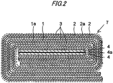
- Fig. 2 is a sectional view of a winding type lithium ion capacitor that is another exemplary embodiment of the invention. Members same as that of the rectangular cell will be described provided with same reference numerals and marks .
- a belt-like positive electrode 1 and negative electrode 2 are wound with a separator 3 interposed therebetween to form a flat cylindrical electrode-winding unit 7 preferably with a separator 3 disposed at the outermost portion and with a negative electrode 2 disposed inside thereof, metal lithium 4 is disposed at for instance a core portion of the electrode-winding unit 7, and thereby a cell is formed.
- Fig. 1 a belt-like positive electrode 1 and negative electrode 2 are wound with a separator 3 interposed therebetween to form a flat cylindrical electrode-winding unit 7 preferably with a separator 3 disposed at the outermost portion and with a negative electrode 2 disposed inside thereof, metal lithium 4 is disposed at for instance a core portion of the electrode-winding unit 7, and thereby a cell is formed.
- the positive electrode 1 is formed as positive electrode active material layers on both sides of a belt-like positive electrode current collector 1a and the negative electrode 2 is formed as negative electrode active material layers on both sides of a belt-like negative electrode current collector 2a.
- the metal lithium 4 one in which a metal lithium foil is pressure bonded on both surfaces of a porous current collector 4a is preferred.
- the positive electrode current collector 1a and negative electrode current collector 2a are formed of a porous material same as the laminate type.
- the metal lithium 4 is short-circuited with the negative electrode 2, from the metal lithium 4 disposed at a core portion, lithium ion move through hole portions of the both current collectors and thereby a predetermined amount of lithium ion is doped to the negative electrode 2 of the electrode-winding unit 7.
- metal lithium may be disposed at an outer periphery portion of an electrode-winding unit 7 to allow lithium ion moving from an external side of the electrode-winding unit 7 to a center portion thereof to dope or the metal lithium may be disposed at both of a center portion and an outer periphery portion of the electrode-winding unit 7 to allow doping lithium ion from both of internal and external sides of the electrode-winding unit 7.
- the metal lithium can be similarly disposed.
- the LIC according to the invention includes a positive electrode made of a material capable of reversibly doping lithium ion and/or anion and a negative electrode made of a material capable of reversibly doping lithium ion, and has a non-protonic organic electrolytic solution of a lithium salt as an electrolytic solution.
- a positive electrode potential after the positive electrode and the negative electrode are short-circuited is 2. 0V (relative to Li/Li + ) or less.
- a conventional electric double layer capacitor usually, in a positive electrode and a negative electrode, same active material (mainly activated charcoal) is used by a substantially same amount.
- the active material has a potential of substantially 3 V when a cell is assembled and, when a capacitor is charged, while anion forms an electric double layer on a positive electrode surface to raise a positive electrode potential, cation forms an electric double layer on a negative electrode surface to lower a potential.
- anion and cation are released from the positive electrode and the negative electrode into an electrolytic solution to lower and raise the potentials respectively to the proximity of 3 V.
- an ordinary carbon material has a potential of substantially 3 V; accordingly, an organic electrolyte capacitor in which both the positive electrode and the negative electrode use the carbon material becomes substantially 3 V in both of the positive electrode and negative electrode potentials after the positive electrode and the negative electrode are short-circuited.
- a positive electrode potential after the positive electrode and the negative electrode are short-circuited is 2.0 V (Li/Li + , same below) or less. That is, in the invention, the positive electrode uses an active material capable of reversibly doping lithium ion and/or anion, the negative electrode uses an active material capable of reversibly doping lithium ion, and lithium ion is doped in advance to the negative electrode and/or positive electrode so that a positive electrode potential after the positive electrode and the negative electrode are short-circuited may be 2.0 V or less.
- To dope lithium ion in advance means to supply lithium ion from a lithium ion supply source such as metal lithium other than the positive electrode and negative electrode to dope.
- a positive electrode potential after the positive electrode and the negative electrode are short-circuited is 2.0 V or less means a case where either one of (A) a positive electrode potential obtained when after lithium ion is doped, a positive electrode terminal and a negative electrode terminal of a capacitor cell are directly connected with a conductive wire and left there for 12 hr or more, the short circuit is released, and a measurement is carried out within 0.5 to 1.5 hr and (B) a positive electrode potential obtained when after a constant current discharge is applied over 12 hr or more to 0 V by use of a charge and discharge test machine and a measurement is carried out within 0.5 to 1.5 hr is 2.0 V or less.
- a positive electrode potential is 2.0 V or less after the positive electrode and the negative electrode are short-circuited means that the positive electrode potential becomes 2.0 V or less after short-circuiting in any one of states of, without restricting only to a state immediately after the lithium ion is doped, a charging state, a discharging state or the case of short-circuiting after charge and discharge are repeated.
- the positive electrode potential becoming 2.0 V or less after the positive electrode and negative electrode are short-circuited will be detailed below.
- activated carbon and carbon materials usually have a potential of substantially 3 V.
- both potentials become substantially 3 V, even after the short-circuiting, the positive electrode potential remains at substantially 3 V.
- the upper limit of the charging voltage is determined as a voltage where the electrolytic solution is not decomposed due to a rise in the positive electrode potential. Accordingly, when the positive electrode potential is set to the upper limit, by an amount of decrease in the negative electrode potential, the charging voltage can be heightened.
- lithium ion is preferably separately doped from a lithium ion supply source such as metal lithium to a negative electrode. Since the lithium ion is doped from other than the positive electrode and negative electrode, upon short-circuiting, an equilibrium potential is established between the positive electrode, negative electrode and metal lithium; accordingly, both the positive electrode potential and negative electrode potential become 3.0 V or less. The more abundant an amount of metal lithium becomes, the lower the equilibrium potential becomes.
- an amount of lithium ion doped to the negative electrode is necessarily controlled so that a positive electrode potential after the short-circuiting may be 2.0 V or less.
- the positive electrode potential after the positive electrode and the negative electrode are short-circuited becomes 2.0 V or less means as mentioned above that separately from the positive electrode and the negative electrode of the LIC, lithium ion is supplied to the positive electrode and/or negative electrode.
- the lithium ion may be doped to either one or both of the negative electrode and the positive electrode.
- a dope amount of the lithium ion becomes much. In this case, the positive electrode potential becomes lower and the lithium ion is irreversibly consumed.
- the positive electrode potential after the positive electrode and the negative electrode are short-circuited is higher than 2.0 V, since an amount of lithium ion supplied to the positive electrode and/or negative electrode is slight, the energy density is small.
- 2.0 V or less is preferred, and in order to obtain further higher energy density 1.
- 0 V or less is preferred. That the positive electrode potential after the positive electrode and negative electrode are short-circuited becomes lower is in other words that an amount of lithium ion supplied to the negative electrode becomes much upon charging a cell.
- the capacitance of the negative electrode increases, a variation of the negative electrode potential becomes smaller.
- a variation of the positive electrode potential becomes larger and the capacitance and capacity of the cell become larger, and thereby high energy density can be obtained.
- the positive electrode potential becomes lower than 1.0 V, though depending on the positive electrode active material, inconveniences such as gas generation and irreversible consumption of the lithium ion are generated, resulting in difficulty in measuring the positive electrode potential. Furthermore, when the positive electrode potential becomes too low means that a negative electrode weight is excessive, conversely the energy density is lowered. Accordingly, in general, the positive electrode potential is 0.1 V or more and preferably 0.3 V or more.
- the capacitance and the capacitance are defined as shown below.
- the capacitance of a cell shows a gradient of a discharge curve of a cell and has a unit of F (farad).
- the capacitance per weight of a cell is a value obtained by dividing the capacitance of the cell by a total weight of weight of the positive electrode active material and weight of negative electrode active material filled in the cell and has a unit of F/g.
- the capacitance of the positive electrode shows a gradient of a discharge curve of the positive electrode and has a unit of F.
- the capacitance per weight of the positive electrode is a value obtained by dividing the capacitance of the positive electrode by weight of the positive electrode active material filled in the cell and has a unit of F/g.
- the capacitance of the negative electrode shows a gradient of a discharge curve of the negative electrode and has a unit of F.
- the capacitance per weight of the negative electrode is a value obtained by dividing the capacitance of the negative electrode by weight of the negative electrode active material filled in the cell and has a unit of F/g.
- the cell capacity is a product of difference of a discharge start voltage and a discharge end voltage of a cell, that is, a variation of voltage and the capacity of the cell, and has a unit of C (Coulomb).
- 1 C is an amount of electricity when a current of 1 A flows during 1 second
- the cell capacity is expressed in terms of mAh.
- the positive electrode capacity is a product of difference of the positive electrode potential at the discharge start and the positive electrode potential at the discharge end (variation of positive electrode potential) and the capacitance of the positive electrode, and has a unit of C or mAh.
- the negative electrode capacity is a product of difference of the negative electrode potential at the discharge start and the negative electrode potential at the discharge end (variation of negative electrode potential) and the capacitance of the negative electrode, and has a unit of C or mAh.
- the cell capacity, the positive electrode capacity and the negative electrode capacity coincide with each other.
- the invention is characterized in that in the LIC, when the capacitance per unit weight of the positive electrode, the weight of the positive electrode active material, the capacitance per weight of the negative electrode and the weight of the negative electrode active material, respectively, are expressed by C+(F/g), W + (g), C - (F/g) and W - (g), a value of (C - ⁇ W - ) / (C + ⁇ W + ) is 5 or more and preferably 10 or more.
- the capacity retention rate of the cell can be improved, and thereby the cell can be made higher in the endurance and longer in the lifetime.
- the (C - ⁇ W - ) / (C + ⁇ W + ) is less than 5, since a diminishing rate of the cell capacity when C - is diminished due to repeated use of the cell increases to lower the capacity retention rate, the cell lifetime becomes shorter.
- the weight of the positive electrode active material, weight of the negative electrode active material and an amount of lithium ion doped to the negative electrode are made appropriate so that the (C - ⁇ W - ) / (C + ⁇ W + ) may be 5 or more, the lifetime of the LIC in the invention can be made longer.
- the lifetime can be made longer in the selected positive electrode active material and negative electrode active material.
- an amount of lithium ion doped to the negative electrode is made larger to make the capacitance per weight of the negative electrode larger (increase in C - ), the lifetime can be made longer.
- an amount of lithium ion doped to the negative electrode since there are restrictions such as the safety of the cell and a limit of a doping amount of the lithium ion in the negative electrode active material, is usually preferably prioritized to make a weight ratio of the negative electrode larger (increase in W - ).
- an amount of lithium ion doped to the negative electrode is increased within a range that does not cause the disturbance to increase C-.
- the value of (C - ⁇ W - ) / (C + ⁇ W + ) can be comprehensively determined so as to be 5 or more.
- a value of (C - ⁇ W - )/ (C + ⁇ W + ) can be made 5 or more.
- the weight ratio of the negative electrode is made larger (an increase in W - ) to render the (C - ⁇ W - ) / (C + ⁇ W + ) 5 or more, even when the capacitance C- per unit weight of the negative electrode decreases as the cell is repeatedly used, since W - is set larger, sufficient negative electrode capacitance can be secured. Furthermore, when the C - is set larger as well, even after the C - decreases, sufficient negative electrode capacitance can be secured. Accordingly, the diminishing rate of the electrostatic capacitance of the cell can be made smaller compared with a case where the (C - ⁇ W - ) / (C + ⁇ W + ) is less than 5.
- the value of (C - ⁇ W - ) / (C + x W + ) is preferably smaller than a certain value.
- a practical value of (C - ⁇ W - )/(C + ⁇ W + ) is, from viewpoint of easiness of securing a high capacitance and high voltage LIC, preferably 20 or less.
- the negative electrode active material has the capacitance per unit weight three-times or more that of the positive electrode active material and the weight of the positive electrode active material is larger than that of the negative electrode active material.
- the positive electrode active material that is used substantially determines the capacitance of the positive electrode. Accordingly, when an amount of lithium ion doped in advance to the negative electrode is controlled by taking the capacitance of the positive electrode into consideration, capacitance three times or more that the capacitance per unit weight of the positive electrode can be secured and an amount of the positive electrode active material can be made larger than that the negative electrode active material. Thereby, a capacitor higher in the voltage and capacity than an existing electric double layer capacitor can be obtained.
- weight of the negative electrode active material is preferably larger than weight of the negative electrode active material and more preferably in the range of 1.1 to 10 times. When it is less than 1.1 times, capacity difference from an existing electric double layer capacitor becomes small. When it exceeds 10 times, conversely, in some cases, the capacity becomes smaller than that of the existing electric double layer capacitor and difference of thicknesses of the positive electrode and negative electrode becomes too large to be unfavorable from the viewpoint of cell configuration.
- a positive electrode current collector and a negative electrode current collector of the invention various materials proposed generally in applications such as an organic electrolytic solution may be used. That is, in the positive electrode current collector, aluminum and stainless steel can be preferably used. In the negative electrode current collector, stainless steel, copper and nickel can be preferably used. These can be used in various shapes such as foil or net. In particular, in order to dope lithium ion in advance to the negative electrode and/or positive electrode, one provided with a hole penetrating through front and back surfaces is preferred. For instance, expanded metal, punching metal, metal mesh, foamed body or a porous foil provided with a throughhole by etching can be cited. The throughhole of the electrode current collector may be formed appropriately in circle, rectangle or others.
- the throughhole of the electrode current collector is at least partially clogged with a conductive material that is difficult to fall and a positive electrode and a negative electrode are formed thereon.
- a shape and number of throughholes of the electrode current collector can be appropriately set so that lithium ion in an electrolytic solution described below may move between front and back surfaces of the electrode without being interrupted by the electrode current collector and the throughhole can be readily clogged with the conductive material.
- the porosity of the electrode current collector is defined as obtained in terms of percentage of a ratio of ⁇ 1 - (weight of current collector/true specific gravity of the current collector)/(apparent volume of current collector) ⁇ .
- the porosity of the electrode current collector used in the invention is usually in the range of 10 to 79% and preferably in the range of 20 to 60%.
- the porosity and a hole diameter of the electrode current collector are desirably appropriately selected from the above range considering a structure of the cell and the productivity thereof.
- the negative electrode active material is not particularly restricted.
- graphite, non-graphitizable carbon and a polyacene semiconductor (PAS) that is a pyrolysis product of an aromatic condensate polymer and has a polyacene skeleton structure where a ratio of numbers of hydrogen atoms and carbon atoms (hereinafter, referred to as H/C) is in the range of 0.50 to 0.05 can be cited.
- PAS polyacene semiconductor
- H/C polyacene semiconductor
- an amount of lithium ion doped is desirably appropriately set in the range of doping capability of lithium ion of the active material.
- the PAS having an amorphous structure, does not exhibit a structural change such as swelling and contraction at the doping and dedoping of the lithium ion to be excellent in the cycle characteristics. Furthermore, the PAS, having a molecular structure (higher structure) isotropic to the doping and dedoping of the lithium ion, has the characteristics excellent in the rapid charging and rapid discharge as well. Accordingly, the PAS is preferred as a negative electrode active material.
- the aromatic condensate polymer that is a precursor of the PAS is a condensate between an aromatic hydrocarbon compound and aldehyde.
- aromatic hydrocarbon compound so-called phenols such as phenol, cresol and xylenol can be preferably used.
- methylene/bisphenols expressed by a formula below (here, x and y, respectively and independently, express 0, 1 or 2) or hydroxy/biphenyls or hydroxynaphthalenes can be used. Above all, practically, phenols are preferred and phenol is particularly preferred.
- aromatic condensate polymer amodified aromatic condensate polymer in which an aromatic hydrocarbon compound having the phenolic hydroxyl group is partially substituted with an aromatic hydrocarbon compound that does not have a phenolic hydroxyl group such as xylene, toluene or aniline such as a condensate of phenol, xylene and formaldehyde can be used as well. Still furthermore, a modified aromatic polymer that is substituted with melamine or urea can be used and a furan resin is preferred as well.
- the PAS is used as an insoluble and infusible base material and the insoluble and infusible base material can be produced from, for instance, the aromatic condensate polymer as follows. That is, when the aromatic condensate polymer is gradually heated up to an appropriate temperature in the range of 400 to 800°C under a non-oxidizing atmosphere (including vacuum atmosphere), an insoluble and infusible base material having the H/C in the range of 0.5 to 0.05 and preferably in the range of 0.35 to 0.10 can be obtained.
- a producing method of the insoluble and infusible base material is not restricted to the above method. According to a method described in for instance JP-B 3-24024 , an insoluble and infusible base material that has above-mentioned H/C and the specific surface area due to the BET method of 600 m 2 /g or more can be obtained as well.
- the insoluble and infusible base material used in the invention has a main peak at a position of 24° or less by 2 ⁇ and, other than the main peak, another broad peak in the range of 41 through 46°. That is, the insoluble and infusible base material has a polyacene skeleton structure where an aromatic polycyclic structure is appropriately developed and that has an amorphous structure; accordingly, since the lithium ion can be stably doped, the insoluble and infusible base material can be preferably used as an active material for a lithium ion electric storage device.
- the negative electrode active material preferably has a pore diameter of 3 nm or more and a pore volume of 0.10 mL/g or more.
- the upper limit of the pore diameter is not limited but usually in the range of 3 to 50 nm.
- the range of the pore volume is not particularly limited but usually in the range of 0.10 to 0.5 mL/g and preferably in the range of 0.15 to 0.5 mL/g.
- a negative electrode is formed from the negative electrode active material powder such as the carbon material or the PAS on the negative electrode current collector, and, as a process therefor, without restricting to a particular method, known processes can be used. Specifically, a powder of a negative electrode active material, a binder and, as needs arise, a conductive powder are dispersed in an aqueous or organic solvent to prepare a slurry, the slurry is coated on the current collector or may be formed in advance into a sheet, followed by sticking the sheet to a current collector to form a negative electrode.
- binder for instance, rubber binders such as SBR; fluorine-containing resins such as polytetrafluoroethylene and polyvinylidene fluoride; and thermoplastic resins such as polypropylene, polyethylene and polyacrylate can be used.
- a usage amount of the binder though different depending on the kind of the negative electrode active material and a shape of the electrode, is in the range of 1 to 20% by weight and preferably in the range of 2 to 10% by weight to the negative electrode active material.
- a usage amount of the conductive material though different depending on the conductivity of the negative electrode active material and a shape of the electrode, is preferably added at a ratio in the range of 2 to 40% by weight to the negative electrode active material.
- a thickness of the negative electrode active material is designed from a balance with a thickness of the positive electrode active material so that the energy density of the cell may be secured.
- one surface of the current collector usually has a thickness in the range of 15 to 100 ⁇ m and preferably in the range of 20 to 80 ⁇ m.
- the positive electrode contains a positive electrode active material that can reversibly dope lithium ion and/or anion such as tetrafluoroborate.
- a positive electrode active material that can reversibly dope lithium ion and/or anion
- activated carbon for instance, activated carbon, a conductive polymer or a polyacene organic semiconductor (PAS) that is a pyrolysis product of an aromatic condensate polymer and has a polyacene skeleton structure where the H/C is in the range of 0.05 to 0.50 can be cited.
- PAS polyacene organic semiconductor
- a method of forming a positive electrode on a positive electrode current collector with the positive electrode active material is substantially same as that of the negative electrode; accordingly, it will be omitted detailing here.
- an electrolytic solution used in the LIC of the invention an electrolyte that can transport lithium ion is used.
- an electrolyte one that is usually in liquid and can be impregnated in a separator is preferred.
- a solvent of the electrolyte a non-protonic organic solvent that can form a non-protonic organic solvent electrolytic solution can be preferably used.
- non-protonic organic solvents for instance, ethylene carbonate, propylene carbonate, dimethyl carbonate, diethyl carbonate, ethylmethyl carbonate, ⁇ -butyrolactone, acetonitrile, dimethoxyethane, tetrahydrofuran, dioxolane, methylene chloride and sulfolane canbe cited. Furthermore, at least two kinds of the non-protonic organic solvents may be mixed and used.
- electrolytes that can transport lithium ion and is not electrolyzed even under a high voltage and where lithium ion can stably exist can be used.
- electrolytes preferably include lithium salts such as LiClO 4 , LiAsF 6 , LiBF 4 , LiPF 6 , LiN(C 2 F 5 SO 2 ) 2 and LiN(CF 3 SO 2 ) 2 .
- a concentration of the electrolyte in the electrolytic solution is preferably set at least at 0.1 mol/L or more and more preferably in the range of 0.5 to 1.5 mol/L.
- a non-conductive porous body having a communicating hole that has the durability to the electrolytic solution or electrode active materials can be used.
- resins such as cellulose (paper), polyethylene and polypropylene can be cited and known materials can be used. Among these, cellulose (paper) is excellent from the viewpoints of the durability and economic efficiency.
- non-woven fabric of paper or resin is preferred.
- a thickness of the separator, without restricting particularly, is preferably in the range of substantially 20 to 50 ⁇ m.
- a metal lithium foil that is used as a lithium ion supply source for doping lithium ion in advance to a negative electrode and/or positive electrode is formed of a material that contains at least a lithium element such as metal lithium or a lithium-aluminum alloy and can supply lithium ion.
- a metal lithium foil that can dope a predetermined amount of lithium ion to the negative electrode and/or positive electrode is preferably disposed.
- a conductive porous body is preferred as mentioned above.
- a metal porous body such as a stainless mesh that does not react with metal lithium can be preferably used.
- a material of an exterior case is not particularly restricted. Metal materials such as iron and aluminum, plastic materials or composite materials obtained by laminating these that are generally used in batteries or capacitors can be used. Furthermore, a shape of the exterior case is not particularly restricted. However, from viewpoints of miniaturization and weight saving of capacitors, a film type exterior case that uses a laminated film of aluminum and a polymer such as nylon and polypropylene is preferred. In what follows, specific examples will be detailed.
- a phenol resin molded sheet having a thickness of 0.5 mm was put in a Siliconit electric furnace and heated under a nitrogen atmosphere to 550°C at a temperature-up speed of 50°C/hr, followed by further heating to 800°C at a temperature-up speed of 10°C/hr, further followed by heat-treating, and thereby PAS was synthesized.
- PAS plate was pulverized by use of a ball mill and thereby a PAS powder having an average particle diameter of substantially 4 ⁇ m was obtained.
- the PAS powder had the H/C ratio of 0.1.
- the slurry was coated by use of a roll coater on both surfaces of a negative electrode current collector made of a copper expanded metal (produced by Nippon Metal Industry Co., Ltd.) having a thickness of 32 ⁇ m (porosity: 57%) to form a negative electrode layer, followed by vacuum drying, and thereby a negative electrode 1 having a total thickness (sum total of thicknesses of electrode layers on both surfaces of the negative electrode and a thickness of negative electrode current collector) of 78 ⁇ m was obtained.
- a total thickness (sum total of current collector thickness and conductive layer thickness) was 52 ⁇ m and the throughhole was substantially clogged with the conductive paint.
- the positive electrode slurry was coated by use of a roll coater on both surfaces of the positive electrode current collector to form positive electrode layers, followed by vacuum drying, and thereby a positive electrode 1 having a thickness of an entire positive electrode (sum total of thicknesses of electrode layers on both surfaces of a positive electrode, thicknesses of conductive layers on both surfaces and a thickness of a positive electrode current collector) of 182 ⁇ m was obtained.
- a sheet having a size of 1.5 cm ⁇ 2.0 cm was cut and used as an evaluation negative electrode.
- the negative electrode and metal lithium having a size of 1.5 cm ⁇ 2.0 cm and a thickness of 200 ⁇ m as a counter electrode were assembled through a polyethylene nonwoven fabric having a thickness of 50 ⁇ m as a separator to prepare a simulated cell.
- metal lithium was used.
- As an electrolytic solution a solution obtained by dissolving LiPF 6 in propylene carbonate at a concentration of 1 mol/l was used. Under a charging current of 1 mA, to weight of a negative electrode active material, lithium ion of 600 mAh/g was doped, followed by discharging under 1 mA to 1.5 V. From the discharging time during which the potential varies by 0.2 V from the negative electrode potential 1 min after the discharge start, the capacitance per unit weight of the negative electrode was obtained and found to be 1300 F/g.
- a sheet having a size of 1.5 cm ⁇ 2.0 cm was cut and used as evaluation positive electrode.
- the positive electrode and metal lithium having a size of 1.5 cm ⁇ 2.0 cm and a thickness of 200 ⁇ m as a counter electrode were assembled through a polyethylene nonwoven fabric having a thickness of 50 ⁇ m as a separator to prepare a simulated cell.
- metal lithium was used.
- As an electrolytic solution a solution obtained by dissolving LiPF 6 in propylene carbonate at a concentration of 1 mol/l was used.
- the charging was carried out under a charging current of 1 mA to 3. 6 V, followed by applying constant voltage charging, after a total charging time of 1 hr, further followed by discharging under 1 mA to 2.5V. From a discharging time between 3.6 V to 2.5 V, the capacitance per unit weight of the positive electrode was obtained and found to be 140 F/g.
- an aluminum positive electrode terminal having a width of 3 mm, a length of 50 mm and a thickness of 0.1 mm, on a sealing portion of which a sealant film is hot-sealed in advance was superposed and welded by ultrasonic.
- a nickel negative electrode terminal having a width of 3 mm, a length of 50 mm and a thickness of 0.1 mm, on a sealing portion of which a sealant film is hot-sealed in advance was superposed and welded by ultrasonic, followed by disposing between an exterior film deep drawn to a length of 60 mm, a width of 30 mm and a depth of 3 mm and an exterior film that is not deep drawn.
- a negative electrode 2 having a total thickness (sum total of thicknesses of electrode layers on both surfaces of the negative electrode and a thickness of negative electrode current collector) of 84 ⁇ m was obtained.
- a positive electrode 2 having a thickness of entire positive electrode (sum total of thicknesses of electrode layers on both surfaces of a positive electrode, thicknesses of conductive layers on both surfaces and a thickness of a positive electrode current collector) of 225 ⁇ m was obtained.
- capacitance per unit weight of the negative electrode 2 was obtained and found to be 1300 F/g.
- capacitance per unit weight of the positive electrode 2 was obtained and found to be 80 F/g.
- the capacitance retention rate showed such an excellent value as 90.2% that is more excellent than example 1.
- a value of (C - ⁇ W - ) / (C + ⁇ W + ) of example 2 was 10.9; accordingly, when a value of (C - ⁇ W - ) / (C + ⁇ W + ) was made 10 or more, a capacitor that combines excellent endurance and high energy density was obtained. Accordingly, when the endurance is considered important, a value of (C - ⁇ W - ) / (C + ⁇ W + ) is preferably set at 10 or more.
- a positive electrode 3 having a thickness of entire positive electrode (sum total of thicknesses of electrode layers on both surfaces of a positive electrode, thicknesses of conductive layers on both surfaces and a thickness of a positive electrode current collector) of 181 ⁇ m was obtained.
- capacitance per unit weight of the positive electrode 3 was obtained and found to be 160 F/g.
- a value of (C - ⁇ W - ) / (C + ⁇ W + ) of example 3 was 6.8; accordingly, even when a positive electrode active material having high capacitance was used, when a value of (C - ⁇ W - ) / (C + ⁇ W + ) is made 5 or more, a capacitor that combines excellent endurance and high energy density was obtained.
- a negative electrode 3 having a total thickness (sum total of thicknesses of electrode layers on both surfaces of the negative electrode and a thickness of negative electrode current collector) of 66 ⁇ m. was obtained.
- the capacitance per unit weight of the negative electrode 3 was obtained and found to be 2600 F/g.
- Furfuryl alcohol that is a raw material of furan resin carbon was held at 60°C for 24 hr to harden the resin, and thereby a black resin was obtained.
- the obtained black resin was put in a stationary electric furnace, heated to 1200°C in 3 hr in a nitrogen atmosphere and held there for 2 hr. After leaving to cool, a sample was taken out and pulverized by use of a ball mill, and thereby non-graphitizable carbon powder having an average particle diameter of substantially 8 ⁇ m was obtained.
- the H/C value of the non-graphitizable carbon powder was 0.008.
- a negative electrode 4 having an entire thickness (sum total of thicknesses of electrode layers on both surfaces of the negative electrode and a thickness of the negative electrode current collector) of 63 ⁇ m was obtained.
- a positive electrode 4 having a thickness of an entire positive electrode (sum total of thicknesses of electrode layers on both surfaces of the positive electrode, thicknesses of the conductive layers on both surfaces and a thickness of the positive electrode current collector) of 204 ⁇ m was obtained.
- the capacitance per unit weight of the negative electrode 4 was measured and found to be 6200 F/g.
- the capacitance per unit weight of the positive electrode 4 was measured and found to be 140 F/g.
- the capacitance C - per weight of the negative electrode was set larger to set a value of (C- ⁇ W - )/(C + ⁇ W + ) such a large value as 22.8. Accordingly, with a value of (C - ⁇ W - )/(C + ⁇ W + ) setting 10 or more, a positive electrode weight ratio as well could be set larger; as the result, a cell higher in the capacitance and energy density than that of cells of other examples could be obtained.
- the capacitance retention rate after 2000 hr of the high temperature voltage application test shows very excellent endurance such as 94.7%. Accordingly, when a value of (C - ⁇ W - ) / (C + ⁇ W + ) was set 10 or more with a negative electrode having larger capacitance per unit weight, a capacitor that combines more excellent endurance and very high energy density was obtained.
- a negative electrode 5 having a total thickness (sum total of thicknesses of electrode layers on both surfaces of the negative electrode and a thickness of negative electrode current collector) of 49 ⁇ m was obtained.
- a positive electrode 5 having a total thickness (sum total of thicknesses of electrode layers on both surfaces of a positive electrode, thicknesses of conductive layers on both surfaces and a thickness of a positive electrode current collector) of 226 ⁇ m was obtained.
- capacitance per unit weight of the negative electrode 5 was obtained and found to be 1300 F/g.
- capacitance per unit weight of the positive electrode 5 was obtained and found to be 140 F/g.
- a value of (C - ⁇ W - ) / (C + ⁇ W + ) is preferably set at 5 or more.
- a negative electrode 6 having a total thickness (sum total of thicknesses of electrode layers on both surfaces of the negative electrode and a thickness of negative electrode current collector) of 40 ⁇ m was obtained.
- a positive electrode 6 having a total thickness (sum total of thicknesses of electrode layers on both surfaces of a positive electrode, thicknesses of conductive layers on both surfaces and a thickness of a positive electrode current collector) of 225 ⁇ m was obtained.
- capacitance per unit weight of the negative electrode 6 was measured and found to be 1300 F/g.
- capacitance per unit weight of the positive electrode 6 was obtained and found to be 160 F/g.
- a value of (C - ⁇ W - ) / (C + ⁇ W + ) is set at 5 or more.
- the lithium ion capacitor of the invention being high in the capacitance and long in the lifetime, is very effective as a driving or auxiliary storage power supply for an electric car or a hybrid electric car. Furthermore, it can be preferably used as well as a driving storage power supply for an electric car or an electric wheelchair, an electric storage device of various kinds of energies such as solar energy or wind-power generation, or a storage power supply for domestic electric appliances.
Applications Claiming Priority (2)
| Application Number | Priority Date | Filing Date | Title |
|---|---|---|---|
| JP2005355409A JP4813168B2 (ja) | 2005-12-08 | 2005-12-08 | リチウムイオンキャパシタ |
| PCT/JP2006/324462 WO2007066728A1 (ja) | 2005-12-08 | 2006-12-07 | リチウムイオンキャパシタ |
Publications (3)
| Publication Number | Publication Date |
|---|---|
| EP1959464A1 EP1959464A1 (en) | 2008-08-20 |
| EP1959464A4 EP1959464A4 (en) | 2013-06-26 |
| EP1959464B1 true EP1959464B1 (en) | 2018-08-29 |
Family
ID=38122873
Family Applications (1)
| Application Number | Title | Priority Date | Filing Date |
|---|---|---|---|
| EP06834217.9A Active EP1959464B1 (en) | 2005-12-08 | 2006-12-07 | Lithium ion capacitor |
Country Status (6)
| Country | Link |
|---|---|
| US (1) | US8203826B2 (ko) |
| EP (1) | EP1959464B1 (ko) |
| JP (1) | JP4813168B2 (ko) |
| KR (1) | KR101086572B1 (ko) |
| CN (1) | CN101326601B (ko) |
| WO (1) | WO2007066728A1 (ko) |
Families Citing this family (13)
| Publication number | Priority date | Publication date | Assignee | Title |
|---|---|---|---|---|
| JP2009200302A (ja) * | 2008-02-22 | 2009-09-03 | Fuji Heavy Ind Ltd | 蓄電デバイスの製造方法および蓄電デバイス |
| JP5266844B2 (ja) * | 2008-03-31 | 2013-08-21 | 日本ケミコン株式会社 | 電気二重層キャパシタ用電極及びその製造方法 |
| KR101861409B1 (ko) * | 2009-12-28 | 2018-05-28 | 제이에무에나지 가부시키가이샤 | 축전 디바이스 |
| US8102642B2 (en) * | 2010-08-06 | 2012-01-24 | International Battery, Inc. | Large format ultracapacitors and method of assembly |
| KR101139426B1 (ko) | 2010-09-28 | 2012-04-27 | 한국에너지기술연구원 | 리튬 이온 커패시터 |
| KR101813306B1 (ko) * | 2010-10-19 | 2017-12-28 | 제이에무에나지 가부시키가이샤 | 리튬 이온 캐패시터 |
| KR101394743B1 (ko) * | 2012-05-16 | 2014-05-16 | 한국에너지기술연구원 | 리튬이온 커패시터 및 그 제조방법 |
| US20150155107A1 (en) * | 2012-07-04 | 2015-06-04 | Sumitomo Electric Industries, Ltd. | Lithium ion capacitor |
| KR101452311B1 (ko) * | 2012-10-31 | 2014-10-21 | 킴스테크날리지 주식회사 | 전기화학셀 |
| US10319536B1 (en) * | 2012-11-19 | 2019-06-11 | Prakash Achrekar | High-capacity electrical energy storage device |
| US9520243B2 (en) * | 2014-02-17 | 2016-12-13 | Korea Institute Of Energy Research | Method of manufacturing flexible thin-film typer super-capacitor device using a hot-melt adhesive film, and super-capacitor device manufactured by the method |
| CN105161309B (zh) * | 2015-09-16 | 2017-11-14 | 中国科学院电工研究所 | 锂离子混合型电容器 |
| EP3850696A4 (en) * | 2018-09-11 | 2022-05-18 | Walsh, Kevin Michael | DIAPHRAGM ELECTRODE ARRANGEMENTS FOR ION CONCENTRATION GRADIENT DEVICES |
Family Cites Families (9)
| Publication number | Priority date | Publication date | Assignee | Title |
|---|---|---|---|---|
| JP3024024B2 (ja) | 1992-06-26 | 2000-03-21 | シーケーディ株式会社 | 冷凍式ドライア |
| JPH08107048A (ja) | 1994-08-12 | 1996-04-23 | Asahi Glass Co Ltd | 電気二重層キャパシタ |
| JP3403856B2 (ja) * | 1995-03-17 | 2003-05-06 | カネボウ株式会社 | 有機電解質電池 |
| JP3800799B2 (ja) * | 1998-04-10 | 2006-07-26 | 三菱化学株式会社 | 電気二重層キャパシター |
| US6862168B2 (en) * | 2001-06-29 | 2005-03-01 | Kanebo, Limited | Organic electrolyte capacitor |
| US7385801B2 (en) * | 2003-03-31 | 2008-06-10 | Fuji Jukogyo Kabushiki Kaisha | Organic electrolyte capacitor |
| WO2005031773A1 (ja) * | 2003-09-30 | 2005-04-07 | Fuji Jukogyo Kabushiki Kaisha | 有機電解質キャパシタ |
| US7548409B2 (en) * | 2004-03-31 | 2009-06-16 | Fuji Jukogyo Kabushiki Kaisha | Organic electrolyte capacitor using a mesopore carbon material as a negative electrode |
| KR101161721B1 (ko) | 2005-03-31 | 2012-07-03 | 후지 주코교 카부시키카이샤 | 리튬 이온 커패시터 |
-
2005
- 2005-12-08 JP JP2005355409A patent/JP4813168B2/ja active Active
-
2006
- 2006-12-07 US US12/090,461 patent/US8203826B2/en active Active
- 2006-12-07 WO PCT/JP2006/324462 patent/WO2007066728A1/ja active Application Filing
- 2006-12-07 KR KR1020087013787A patent/KR101086572B1/ko active IP Right Grant
- 2006-12-07 EP EP06834217.9A patent/EP1959464B1/en active Active
- 2006-12-07 CN CN2006800461675A patent/CN101326601B/zh active Active
Non-Patent Citations (1)
| Title |
|---|
| None * |
Also Published As
| Publication number | Publication date |
|---|---|
| CN101326601B (zh) | 2012-03-21 |
| JP2007158273A (ja) | 2007-06-21 |
| KR20080072712A (ko) | 2008-08-06 |
| EP1959464A4 (en) | 2013-06-26 |
| US8203826B2 (en) | 2012-06-19 |
| EP1959464A1 (en) | 2008-08-20 |
| US20090161296A1 (en) | 2009-06-25 |
| CN101326601A (zh) | 2008-12-17 |
| JP4813168B2 (ja) | 2011-11-09 |
| WO2007066728A1 (ja) | 2007-06-14 |
| KR101086572B1 (ko) | 2011-11-23 |
Similar Documents
| Publication | Publication Date | Title |
|---|---|---|
| EP1959464B1 (en) | Lithium ion capacitor | |
| EP1865520B1 (en) | Lithium ion capacitor | |
| US7817403B2 (en) | Lithium ion capacitor | |
| US7733629B2 (en) | Lithium ion capacitor | |
| EP1942510B1 (en) | Lithium ion capacitor | |
| EP1950780B1 (en) | Lithium ion capacitor | |
| EP2372732B1 (en) | Wound-type accumulator | |
| KR101148562B1 (ko) | 전지 또는 커패시터용 금속 리튬박 | |
| JP2006286919A (ja) | リチウムイオンキャパシタ | |
| EP1975951A1 (en) | Lithium ion capacitor | |
| JP2010157541A (ja) | 捲回型蓄電源 | |
| JP2007067097A (ja) | 捲回型リチウムイオンキャパシタ |
Legal Events
| Date | Code | Title | Description |
|---|---|---|---|
| PUAI | Public reference made under article 153(3) epc to a published international application that has entered the european phase |
Free format text: ORIGINAL CODE: 0009012 |
|
| 17P | Request for examination filed |
Effective date: 20080603 |
|
| AK | Designated contracting states |
Kind code of ref document: A1 Designated state(s): DE FR GB NL |
|
| DAX | Request for extension of the european patent (deleted) | ||
| RBV | Designated contracting states (corrected) |
Designated state(s): DE FR GB NL |
|
| A4 | Supplementary search report drawn up and despatched |
Effective date: 20130529 |
|
| RIC1 | Information provided on ipc code assigned before grant |
Ipc: H01G 11/22 20130101AFI20130524BHEP |
|
| RAP1 | Party data changed (applicant data changed or rights of an application transferred) |
Owner name: FUJI JUKOGYO KABUSHIKI KAISHA |
|
| RAP1 | Party data changed (applicant data changed or rights of an application transferred) |
Owner name: SUBARU CORPORATION |
|
| 17Q | First examination report despatched |
Effective date: 20171010 |
|
| REG | Reference to a national code |
Ref country code: DE Ref legal event code: R079 Ref document number: 602006056223 Country of ref document: DE Free format text: PREVIOUS MAIN CLASS: H01G0009058000 Ipc: H01G0011220000 |
|
| RIC1 | Information provided on ipc code assigned before grant |
Ipc: H01G 9/00 20060101ALN20180309BHEP Ipc: H01G 9/022 20060101ALN20180309BHEP Ipc: H01G 11/06 20130101ALN20180309BHEP Ipc: H01G 11/22 20130101AFI20180309BHEP Ipc: H01G 9/04 20060101ALN20180309BHEP |
|
| GRAP | Despatch of communication of intention to grant a patent |
Free format text: ORIGINAL CODE: EPIDOSNIGR1 |
|
| INTG | Intention to grant announced |
Effective date: 20180426 |
|
| RIC1 | Information provided on ipc code assigned before grant |
Ipc: H01G 9/00 20060101ALN20180413BHEP Ipc: H01G 11/06 20130101ALN20180413BHEP Ipc: H01G 9/022 20060101ALN20180413BHEP Ipc: H01G 11/22 20130101AFI20180413BHEP Ipc: H01G 9/04 20060101ALN20180413BHEP |
|
| GRAS | Grant fee paid |
Free format text: ORIGINAL CODE: EPIDOSNIGR3 |
|
| GRAA | (expected) grant |
Free format text: ORIGINAL CODE: 0009210 |
|
| AK | Designated contracting states |
Kind code of ref document: B1 Designated state(s): DE FR GB NL |
|
| REG | Reference to a national code |
Ref country code: GB Ref legal event code: FG4D |
|
| REG | Reference to a national code |
Ref country code: DE Ref legal event code: R096 Ref document number: 602006056223 Country of ref document: DE |
|
| REG | Reference to a national code |
Ref country code: NL Ref legal event code: MP Effective date: 20180829 |
|
| PG25 | Lapsed in a contracting state [announced via postgrant information from national office to epo] |
Ref country code: NL Free format text: LAPSE BECAUSE OF FAILURE TO SUBMIT A TRANSLATION OF THE DESCRIPTION OR TO PAY THE FEE WITHIN THE PRESCRIBED TIME-LIMIT Effective date: 20180829 |
|
| REG | Reference to a national code |
Ref country code: DE Ref legal event code: R097 Ref document number: 602006056223 Country of ref document: DE |
|
| PLBE | No opposition filed within time limit |
Free format text: ORIGINAL CODE: 0009261 |
|
| STAA | Information on the status of an ep patent application or granted ep patent |
Free format text: STATUS: NO OPPOSITION FILED WITHIN TIME LIMIT |
|
| 26N | No opposition filed |
Effective date: 20190531 |
|
| GBPC | Gb: european patent ceased through non-payment of renewal fee |
Effective date: 20181207 |
|
| PG25 | Lapsed in a contracting state [announced via postgrant information from national office to epo] |
Ref country code: GB Free format text: LAPSE BECAUSE OF NON-PAYMENT OF DUE FEES Effective date: 20181207 |
|
| REG | Reference to a national code |
Ref country code: DE Ref legal event code: R084 Ref document number: 602006056223 Country of ref document: DE |
|
| PGFP | Annual fee paid to national office [announced via postgrant information from national office to epo] |
Ref country code: FR Payment date: 20231221 Year of fee payment: 18 Ref country code: DE Payment date: 20231214 Year of fee payment: 18 |