EP1958531A1 - Ultraschallfrisiervorrichtung - Google Patents
Ultraschallfrisiervorrichtung Download PDFInfo
- Publication number
- EP1958531A1 EP1958531A1 EP06832695A EP06832695A EP1958531A1 EP 1958531 A1 EP1958531 A1 EP 1958531A1 EP 06832695 A EP06832695 A EP 06832695A EP 06832695 A EP06832695 A EP 06832695A EP 1958531 A1 EP1958531 A1 EP 1958531A1
- Authority
- EP
- European Patent Office
- Prior art keywords
- ultrasonic
- face
- vibration
- pressing
- hairs
- Prior art date
- Legal status (The legal status is an assumption and is not a legal conclusion. Google has not performed a legal analysis and makes no representation as to the accuracy of the status listed.)
- Withdrawn
Links
Images


Classifications
-
- A—HUMAN NECESSITIES
- A45—HAND OR TRAVELLING ARTICLES
- A45D—HAIRDRESSING OR SHAVING EQUIPMENT; EQUIPMENT FOR COSMETICS OR COSMETIC TREATMENTS, e.g. FOR MANICURING OR PEDICURING
- A45D1/00—Curling-tongs, i.e. tongs for use when hot; Curling-irons, i.e. irons for use when hot; Accessories therefor
- A45D1/02—Curling-tongs, i.e. tongs for use when hot; Curling-irons, i.e. irons for use when hot; Accessories therefor with means for internal heating, e.g. by liquid fuel
- A45D1/04—Curling-tongs, i.e. tongs for use when hot; Curling-irons, i.e. irons for use when hot; Accessories therefor with means for internal heating, e.g. by liquid fuel by electricity
-
- A—HUMAN NECESSITIES
- A45—HAND OR TRAVELLING ARTICLES
- A45D—HAIRDRESSING OR SHAVING EQUIPMENT; EQUIPMENT FOR COSMETICS OR COSMETIC TREATMENTS, e.g. FOR MANICURING OR PEDICURING
- A45D1/00—Curling-tongs, i.e. tongs for use when hot; Curling-irons, i.e. irons for use when hot; Accessories therefor
- A45D1/06—Curling-tongs, i.e. tongs for use when hot; Curling-irons, i.e. irons for use when hot; Accessories therefor with two or more jaws
- A45D1/08—Curling-tongs, i.e. tongs for use when hot; Curling-irons, i.e. irons for use when hot; Accessories therefor with two or more jaws the jaws remaining parallel to each other during use, e.g. the jaws sliding parallel to each other
-
- A—HUMAN NECESSITIES
- A45—HAND OR TRAVELLING ARTICLES
- A45D—HAIRDRESSING OR SHAVING EQUIPMENT; EQUIPMENT FOR COSMETICS OR COSMETIC TREATMENTS, e.g. FOR MANICURING OR PEDICURING
- A45D1/00—Curling-tongs, i.e. tongs for use when hot; Curling-irons, i.e. irons for use when hot; Accessories therefor
- A45D1/18—Curling-tongs, i.e. tongs for use when hot; Curling-irons, i.e. irons for use when hot; Accessories therefor with combs
-
- A—HUMAN NECESSITIES
- A45—HAND OR TRAVELLING ARTICLES
- A45D—HAIRDRESSING OR SHAVING EQUIPMENT; EQUIPMENT FOR COSMETICS OR COSMETIC TREATMENTS, e.g. FOR MANICURING OR PEDICURING
- A45D1/00—Curling-tongs, i.e. tongs for use when hot; Curling-irons, i.e. irons for use when hot; Accessories therefor
- A45D1/02—Curling-tongs, i.e. tongs for use when hot; Curling-irons, i.e. irons for use when hot; Accessories therefor with means for internal heating, e.g. by liquid fuel
- A45D1/04—Curling-tongs, i.e. tongs for use when hot; Curling-irons, i.e. irons for use when hot; Accessories therefor with means for internal heating, e.g. by liquid fuel by electricity
- A45D2001/045—Curling-tongs, i.e. tongs for use when hot; Curling-irons, i.e. irons for use when hot; Accessories therefor with means for internal heating, e.g. by liquid fuel by electricity the power being supplied by batteries
-
- A—HUMAN NECESSITIES
- A45—HAND OR TRAVELLING ARTICLES
- A45D—HAIRDRESSING OR SHAVING EQUIPMENT; EQUIPMENT FOR COSMETICS OR COSMETIC TREATMENTS, e.g. FOR MANICURING OR PEDICURING
- A45D2200/00—Details not otherwise provided for in A45D
- A45D2200/20—Additional enhancing means
- A45D2200/207—Vibration, e.g. ultrasound
Definitions
- the present invention relates to an ultrasonic wave hair set apparatus which is used to set hairs by pressing hairs to a vibration face performing ultrasonic vibration.
- JPA 2000-333719 Official Gazette discloses a heat-type hair set apparatus that is used to set hairs.
- a heat-type hair set apparatus is provided a heating face heated by a heater on a main frame, and heats hairs by pressing the heating face to the hairs so as to set the hairs.
- the above mentioned heat-type hair set apparatus has disadvantages that power consumption becomes larger, and it damages hairs because the heating face of a high temperature is pressed to the hairs.
- an ultrasonic wave hair set apparatus comprises a vibration face performing ultrasonic vibration instead of the heating face, and vibrates hairs when the hairs are pressed to the vibration face so as to set hairs by heating hairs from within by ultrasonic vibration.
- the ultrasonic wave hair set apparatus has a disadvantage that the portion may be burned.
- a portion of a human body other than hairs typically, finger
- the ultrasonic wave hair set apparatus has a disadvantage that the portion may be burned.
- the conventional heat-type hair set apparatus even if the finger touches the heating face, a user may generally take off the finger from the heating face reflectively , so that the finger is rarely burned.
- the finger may rarely be taken off reflectively , and consequently, there is a possibility that the finger will be heated from within during touching the finger to the vibration face in a long time, and the finger may be burned.
- the present invention is conceived to solve the above mentioned problems of the prior art, and objected to provide an ultrasonic wave hair set apparatus that can prevent a portion of a human body other than hairs to touch the vibration face by mistake.
- An ultrasonic wave hair set apparatus in accordance with an aspect of the present invention comprises a main frame, an ultrasonic vibration generating means which is provided on the main frame and generates ultrasonic vibrations, and a burn injury prevention means that prevent a portion of a human body other than hairs from touching to the vibration face of the ultrasonic wave generating means.
- the burn injury prevention means even if a user touches a portion of a human body other than hairs such as a finger to the ultrasonic vibration generating means of the ultrasonic wave hair set apparatus in long time, the ultrasonic vibration may not be transmitted to the portion of the human body, so that the finger may not be heated from within and the finger may not be burnt injury.
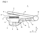
- the ultrasonic wave hair set apparatus in accordance with a first embodiment is configured by a main frame 10 in which a portion near to a rear end thereof serves as a grip 11, an ultrasonic vibration block 2 which is provided in an inside of the main frame 10 near to a front end thereof, a battery 13 and a driving circuit 14 that drives the ultrasonic vibration block 2, an operation switch 15 that controls driving of the ultrasonic vibration block 2, a pinching lever 6 that is rotatably pivoted within a predetermined angle region by a hinge 12 at the rear end of the main frame 10, and a presser plate 7 provided at a position near to the front end of the main frame 10 and to face the ultrasonic vibration block 2, and so on.
- a front face of the presser plate 7 facing the main frame 10 serves as a pressing face.
- the ultrasonic wave hair set apparatus 1 a thing of type driven with a battery is exemplified, but it may be a thing of the type in which a plug of a power cable is inserted into a plug socket of commercial power supply.
- a front end portion of the pinching lever 6 may be biased to depart from the front end portion of the main frame 10 by a spring member (not illustrated), for example.
- the ultrasonic vibration block 2 further comprises an ultrasonic transducer 3 which generates ultrasonic vibrations by energization and an ultrasonic horn 4 which is connected with the ultrasonic transducer 3, amplitude the vibrations generated by the ultrasonic transducer 3 and expands vibration area.
- a surface of the ultrasonic horn 4 serves as a vibration face 5, and it protrudes toward the pinching lever 6 from an upper face of the main frame 10 near to the front end thereof, and disposed to face the pressing face 8 of the above mentioned presser plate 7.
- a cross section of the main frame 10 in a direction parallel to a rotational axis of the hinge 12 is substantially rectangular shape which is oblong in a longitudinal direction X of the main frame 10.
- the vibration face 5 of the ultrasonic horn 4 is a substantially rectangular shape which is oblong in the longitudinal direction X of the main frame 10.
- a pair of comb shaped protection members 9 is provided to enclose the vibration face 5 along both sides of the vibration face 5 of the ultrasonic horn 4 in the longitudinal direction. As shown in FIG.
- the protection member 9 has a plurality of protection protrusions 91 which are arranged with a predetermined distance "d" around the vibration face 5, and serves as a burn injury prevention means that prevents a portion of a human body other than hairs (typically a finger 31) from touching with the vibration face 5.
- it is preferable to elect a distance "w” between a pair of the protection members 91 disposed on both side of the vibration face 5 at the front end of the ultrasonic horn 4 about 3 to 10 mm (w 3-10 mm).
- a pair of the protection members 91 may be formed and attached to the main frame 10 as individual subjects, respectively.
- a pair of the protection members 91 may be formed and attached to the main frame 10 integrally so that stem portions of the protection protrusions 91 are to be a substantially rectangular frame.
- a pair of the protection members 91 may be formed integrally with the main frame 10.
- the pressing face 8 of the presser plate 7 of the pinching lever 6 is formed so that it does not contact with a pair of the protection members 9 of the main frame 10, but contacts only the vibration face 5 of the ultrasonic horn 4 or a bundle 30 of hairs thereon.
- a method to use the ultrasonic wave hair set apparatus is described.
- a bundle of hairs 30 is disposed between the vibration face 5 of the ultrasonic horn 4 or the protection members 9 and the pressing face 8 of the presser plate 7 in a manner so that the arrangement direction of the protection protrusions 91 of the protection members 9 crosses at right angle to the direction of the bundle of hairs 30 in a condition that the front end portion of the pinching lever 6 departs from the front end portion of the main frame 10.
- FIG. 3A a bundle of hairs 30 is disposed between the vibration face 5 of the ultrasonic horn 4 or the protection members 9 and the pressing face 8 of the presser plate 7 in a manner so that the arrangement direction of the protection protrusions 91 of the protection members 9 crosses at right angle to the direction of the bundle of hairs 30 in a condition that the front end portion of the pinching lever 6 departs from the front end portion of the main frame 10.
- the bundle of hairs 30 is pinched between the vibration face 5 of the ultrasonic horn 4 and the pressing face of the presser plate 7 via the protection members 9.
- the ultrasonic oscillator 3 is driven to generate the ultrasonic vibrations.
- the bundle of hairs 30 may be pinched between the vibration face 5 of the ultrasonic horn 4 and the pressing face of the presser plate 7.
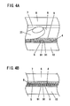
- the protection members 9 are described. As shown in FIG. 4A or FIG. 5A , even if a fingertip 31 is penetrated between the main frame 10 and the pinching lever 6, since a pair of the protection members 9 encloses the vibration face 5 of the ultrasonic horn 4, the fingertip 31 may touch the apexes of the protection protrusions 91 prior to touching the vibration face 5.
- the fingertip 31 rarely touches the vibration face 5 directly in a normal condition that the user penetrates the fingertip 31 between the main frame 10 and the pinching lever 6 unconsciously. Therefore, even if the user penetrates the fingertip 31 between the main frame 10 and the pinching lever 6, the possibility that the ultrasonic vibrations generated by the ultrasonic oscillator 3 and transmitted to the vibration face 5 of the ultrasonic horn 4 is further transmitted to the fingertip 31 becomes much smaller. Consequently, the finger is rarely heated from within and be burned.
- the ultrasonic wave hair set apparatus 1 in accordance with the first embodiment is configured that the presser plate 7 is provided in a portion near to the front end of the pinching lever 6, and the bundle of hairs 30 is pressed to the vibration face 5 of the ultrasonic horn 4 by the pressing face 8 of the presser plate 7, it is not limited to this configuration. Thus, another configuration may be employed if the bundle of hairs 30 can be pressed to the vibration face 5 of the ultrasonic horn 4. In addition, the pinching lever 6 and the presser plate 7 are not necessarily needed.
- the ultrasonic wave hair set apparatus 1 may be moved parallel to the bundle of hairs 30 so as to comb hairs, so that pressure to press the hairs to the vibration face 5 can be ensured by pressure generated by pulling the front end of the bundle of hairs 30 by the user.
- FIGS. 6A and 6B Elements which are the same as or similar to those in the above mentioned first embodiment are designated by the same numerals and the detailed descriptions of them are omitted.
- an ultrasonic vibration block 2 has a plurality of (three lines in the illustrated example) ultrasonic horns 4A to 4C which are arranged in parallel, and a plurality of vibration faces 5A to 5C on the surfaces of them. Furthermore, a plurality (four in the illustrated example) of comb shaped protection members 9A to 9D is provided along both sides of the vibration faces 5A to 5C in longitudinal directions of them.
- a plurality of grooves 71 is formed on a presser plate 7 provided at a portion near to a front end of a pinching lever 6 in a longitudinal direction of the presser plate 7 so as to avoid contacting of apexes of protruding protrusions 91 of the protection members 9B and 9C disposed near to the center among the plurality of the protection members 9A to 9D arranged in parallel other than two of them disposed at both sides.
- the protection protrusions 91 of the protrusion members 9 respectively enclose the vibration faces 5A to 5D of the ultrasonic horns 4A to 4C, so that the fingertip 31 touches the apexes of the protection protrusions 91 before touching the vibration faces 5A to 5C.
- the fingertip 31 rarely touches the vibration faces 5A to 5D directly, so that the possibility that the ultrasonic vibrations transmitted to the vibration faces 5A to 5C of the ultrasonic horns 4A to 4C is further transmitted to the fingertip 31 becomes much smaller. Consequently, the finger is rarely heated from within and be burned.
- the bundle of hairs 30 when the bundle of hairs 30 is penetrated between the main frame 10 and the pinching lever 6, the bundle of hairs 30 can be pinched between the vibration faces 5A to 5C of the ultrasonic horns 4A to 4C and the pressing face 8 of the presser plate 7, and thus, the ultrasonic vibration s generated by the ultrasonic oscillator 3 can be transmitted to the bundle of hairs 30 through the vibrati on faces 5A to 5C of the ultrasonic horn s 4A to 4C. Consequently, when the hairs are combed by moving the ultrasonic wave hair set apparatus 1 parallel to the bundle of hairs 30, the hairs are set straight.
- the ultrasonic wave hair set apparatus 1 in accordance with the second embodiment is not limited to the above mentioned configuration, so that it is possible to provide presser plates simply at positions of the ultrasonic horns 4A to 4C arranged as three lines other than the ultrasonic horn 4B disposed at the center.
- FIGS. 7A to 7C Elements which are the same as or similar to those in the above mentioned first embodiment are designated by the same numerals and the detailed descriptions of them are omitted.
- a spacing detection sensor 20 which detects a distance "D" between a pressing face 8 of a presser plate 7 of a pinching lever 6 and a vibration face 5 of an ultrasonic horn 4 of a main frame 10 at front end portions of them, is comprised as a safety switch further to protection members 9.
- the spacing detection sensor 20 is configured by a push-on switch 21 provided on an opposing face 10a of the main frame 10 which faces the pinching lever 6, and a protrusion 22 provided on an opposing face of the pinching lever 6 which face the main frame 10.
- a protruding height of the protrusion 22 is selected corresponding to the distance "D" between the pressing face 8 of the presser plate 7 and the vibration face 5 of the ultrasonic horn 4.
- the distance "D" between the pressing face 8 of the presser plate 7 and the vibration face 5 of the ultrasonic horn 4 becomes equal to or less than a predetermined distance by which a finger of a user cannot penetrate therethrough, so that a driving circuit 14 drives an ultrasonic oscillator 3 by supplying an electric power so as to generate ultrasonic vibrations.
- a predetermined distance is preferably about 5 mm, for example.
- FIGS. 8A and 8B Elements which are the same as or similar to those in the above mentioned third embodiment are designated by the same numerals and the detailed descriptions of them are omitted.
- an angle detection sensor 25 which detects an angle ⁇ between a pressing face 8 of a presser plate 7 of a pinching lever 6 and a vibration face 5 of an ultrasonic horn 4 of a main frame 10 at front end portions of them, is provided as a safety switch further to protection members 9.
- the angle detection sensor 25 is provided in an inside of a hinge 12, and configured of a moving contact and a stationary contact which are electrically conducted when the angle ⁇ of the pinching lever 6 with respect to the main frame 10 becomes equal to or less than a predetermined angle.
- a distance between the pressing face 8 of the presser plate 7 and the vibration face 5 of the ultrasonic horn 4 becomes equal to or less than a predetermined distance by which a finger of a user cannot penetrate therethrough, so that the angle detection sensor 25 is switched on, and a driving circuit 14 drives an ultrasonic oscillator 3 by supplying an electric power so as to generate ultrasonic vibrations.
- the predetermined angle varies corresponding to allover lengths of the main frame 10 and the pinching lever 6, specific numerical value is nor exemplified, but it is preferable to select an angle by which a distance "D" between the pressing face 8 of the presser plate 7 and the vibration face 5 of the ultrasonic horn 4 of at front end portions of them becomes about 5 mm, for example.
- the driving circuit 14 does not supply the electric power to the ultrasonic oscillator 3, and the ultrasonic oscillator 3 does not generate ultrasonic vibration. Consequently, since no ultrasonic vibration is transmitted to the fingertip 31, the finger may not be heated from within and the finger never be burned.
- an optical encoder which is configured by a light emitting device, a light receiving device, a grating plate, and so on can be used other than the electronic switch.
- the driving circuit 14 counts pulse signal s outputted from the angle detection sensor 25, calculates an angle ⁇ of the pinching lever 6 with respect to the main frame 10, and compares the calculated angle ⁇ with a predetermined angle.
- FIGS. 9A and 9B Elements which are the same as or similar to those in the above mentioned first embodiment are designated by the same numerals and the detailed descriptions of them are omitted.
- a pressure sensor 40 which detects a pressure applied to a pressing face 8, is provided at a position in an inside of a pinching lever 8 and in a rear face side of a presser plate 7. Only when a detection result of the pressure sensor 40 becomes equal to or larger than a predetermined pressure, a driving circuit 14 drives an ultrasonic oscillator 3 by supplying an electric power so as to generate ultrasonic vibrations.
- predetermined pressure it is preferable to be set in 2 kgf, for example.
- the pressure sensor 40 has a following merit further to functions as a safety switch and a burn prevention means. For example, as shown in FIG. 9 , even if a bundle of hairs 30 is pinched between a pressing face 8 and a vibration face 5 of an ultrasonic horn 4, when a force of a user to grasp a grip 11 of the pinching lever 6 and the main frame 10 is weak, that is, a pressure to press the vibration face 5 by the pressing face 8 is insufficient, generation of ultrasonic vibration is restricted. Consequently, it is possible to prevent so-called null oscillation (boil-dry) in which the ultrasonic vibrations are generated in a condition that hairs are pressed to the vibration face 5 insufficiently.
- Such null oscillation is a condition that the ultrasonic horn 4 is oscillated in or near to no-load, so that heat is generated in the ultrasonic horn 4 due to energy loss, and it may cause breakdown if the apparatus.
- the breakdown of the apparatus due to such null oscillation can be prevented.
- the present invention is not limited to the above mentioned embodiments, and it is preferable to comprise at least a main frame, an ultrasonic vibration generating means which is provided on the main frame and generates ultrasonic vibrations, and a burn injury prevention means that prevent a portion of a human body other than hairs from touching the vibration face of the ultrasonic wave generating means.
- the burn injury prevention means even if a user touches a portion of a human body other than hairs such as a finger to the ultrasonic vibration generating means of the ultrasonic wave hair set apparatus in long time, the ultrasonic vibration may not be transmitted to the portion of the human body, so that the finger may not be heated from within and the finger may not be burnt injury.
- the burn injury prevention means may be a comb shaped protection member which is provided along a side face of the vibration face. Since the protection member is formed comb shape, it is possible not only to comb hairs as a brush, but also to provide a stimulus to a portion of a human body when the portion of the human body such as a finger touches the protection member. Therefore , it is thought that a user takes off the portion of the human body from the vibration face quickly, so that even if the portion of the human body touches the vibration face directly, a contacting time can be shortened. Consequently, ultrasonic vibrations transmitted to the portion of the human body is few, so that a finger rarely heated from within, and the finger is never burned.
- the ultrasonic vibration generating means may be configured by an ultrasonic oscillator, and an ultrasonic horn connected to the ultrasonic oscillator and having a rectangular shaped vibration face, and a pair of comb shaped protection members is provided parallel to each other along both sides of the rectangular vibration face in a longitudinal direction thereof. Since the vibration face is guarded from both sides by a pair of the comb shaped protection members, it is possible to increase the above mentioned functions as the brush and the burn injury prevention means.
- it may further comprise a pressing means having a pressing face to press hairs to the vibration face, and the pressing means may be configured so as not to interfere with the comb shaped protection member in a condition that the hairs are pressed to the vibration face. Since the hair is strongly pressed to the vibration face by the pressing means, the ultrasonic vibration can be transmitted to the hairs efficiently. Consequently, hair set effect by the ultrasonic vibrations can be increased.
- it may further comprise a pressing means having a pressing face to press hairs to the vibration face, and a safety switch as the burn injury prevention means, which makes the ultrasonic vibration generating means generate ultrasonic vibrations only when a distance between the pressing face and the vibration face becomes equal to or less than a predetermined distance. If a portion of a human body such as a finger is pinched between the pressing face and the vibration face, the distance between them becomes longer than the predetermined distance. In such case, ultrasonic vibration is never generated by an operation of the safety switch when a portion of a human body such as a finger is pinched between the pressing face and the vibration face, and thus, the user is never burned.
- the pressing means may be configured by a pinching lever which is rotatably held on the main frame and a presser plate which is provided on the pinching lever;
- the ultrasonic vibration generating means may be configured by an ultrasonic oscillator, and an ultrasonic horn connected to the ultrasonic oscillator;
- the safety switch may be configured by a distance detection sensor which detects a distance between a pressing face of the presser plate and a vibration face of the ultrasonic horn, and a driving circuit which drives the ultrasonic vibration generating means to generate ultrasonic vibration only when the distance detected by the distance detection sensor becomes equal to or less than a predetermined distance.
- the pressing means may be configured by a pinching lever which is rotatably held on the main frame and a presser plate which is provided on the pinching lever;
- the ultrasonic vibration generating means may be configured by an ultrasonic oscillator, and an ultrasonic horn connected to the ultrasonic oscillator;
- the safety switch may be configured by an angle detection sensor which detects an angle of the pinching lever with respect to the main frame, and a driving circuit which drives the ultrasonic vibration generating means to generate ultrasonic vibration only when the angle detected by the angle detection sensor becomes equal to or less than a predetermined angle.
- a reliable safety switch can be configured with using a relatively simple and inexpensive element.
- a pressing means having a pressing face which presses hairs to a vibration face; a pressure detection sensor which detects a pressure applied to the pressing face; and a driving circuit which drives the ultrasonic vibration generating means to generate ultrasonic vibrations only when a pressure detected by the pressure detection sensor becomes equal to or larger than a predetermined pressure.
- a pressure sensor such as a piezoelectric device on a rear face of the pressing face, for example, a reliable safety switch can be configured with using a relatively simple and inexpensive element.
- This pressure detection sensor can be used as the above mentioned safety switch.
- a portion of a human body such as a fingertip is pinched between the pressing face and the vibration face
- the ultrasonic vibrations are never generated when the user does not apply a pressure equal to or larger than the predetermined pressure purposely.
- a pressure equal to or larger than the predetermined pressure is applied between the pressing face and the vibration face
- stimulus may be applied to the portion of the human body pinched between the pressing face and the vibration face, so that the user may take off the portion from between the pressing face and the vibration face. Consequently, the user can be prevented from burn injury.
- the ultrasonic horn may be oscillated in or near to no-load, so that heat is generated in the ultrasonic horn due to energy loss, and thus, it may cause breakdown of the apparatus (so-called null vibration or boil-dry).
- null vibration breakdown of the apparatus
- the ultrasonic vibration may not be generated by the pressure detection sensor if the pressure equal to or larger than the predetermined pressure is applied between the pressing face and the vibration face, it is possible to prevent the breakdown of the apparatus due to null vibration.
- the ultrasonic wave hair set apparatus may be configured in combination with the above mentioned elements arbitrarily.
Landscapes
- Hair Curling (AREA)
- Surgical Instruments (AREA)
- Percussion Or Vibration Massage (AREA)
Applications Claiming Priority (2)
| Application Number | Priority Date | Filing Date | Title |
|---|---|---|---|
| JP2005341251A JP4839800B2 (ja) | 2005-11-25 | 2005-11-25 | 超音波ヘアセット器 |
| PCT/JP2006/322805 WO2007060872A1 (ja) | 2005-11-25 | 2006-11-16 | 超音波ヘアセット装置 |
Publications (2)
| Publication Number | Publication Date |
|---|---|
| EP1958531A1 true EP1958531A1 (de) | 2008-08-20 |
| EP1958531A4 EP1958531A4 (de) | 2009-08-05 |
Family
ID=38067103
Family Applications (1)
| Application Number | Title | Priority Date | Filing Date |
|---|---|---|---|
| EP06832695A Withdrawn EP1958531A4 (de) | 2005-11-25 | 2006-11-16 | Ultraschallfrisiervorrichtung |
Country Status (7)
| Country | Link |
|---|---|
| US (1) | US20090266378A1 (de) |
| EP (1) | EP1958531A4 (de) |
| JP (1) | JP4839800B2 (de) |
| KR (1) | KR101010168B1 (de) |
| CN (1) | CN101312673B (de) |
| RU (1) | RU2407412C2 (de) |
| WO (1) | WO2007060872A1 (de) |
Cited By (8)
| Publication number | Priority date | Publication date | Assignee | Title |
|---|---|---|---|---|
| GB2461055A (en) * | 2008-06-18 | 2009-12-23 | Hair Tools Ltd | Vibrating hair tool |
| EP2198735A1 (de) | 2008-12-17 | 2010-06-23 | WIK Far East Ltd. | Haarformgerät |
| FR2940893A1 (fr) * | 2009-01-15 | 2010-07-16 | Seb Sa | Appareil de coiffure |
| EP2332436A1 (de) * | 2009-11-04 | 2011-06-15 | Panasonic Electric Works Co., Ltd | Haarglätter |
| FR3042958A1 (fr) * | 2015-11-02 | 2017-05-05 | Seb Sa | Appareil de coiffure de type lisseur avec peigne optimise |
| EP3460433A1 (de) * | 2017-09-20 | 2019-03-27 | Koninklijke Philips N.V. | Vorrichtung zur messung von haareigenschaften |
| EP3721751A1 (de) * | 2019-04-08 | 2020-10-14 | Koninklijke Philips N.V. | Haarstylingvorrichtung |
| RU2785051C2 (ru) * | 2017-09-20 | 2022-12-02 | Конинклейке Филипс Н.В. | Устройство для измерения свойств волос |
Families Citing this family (24)
| Publication number | Priority date | Publication date | Assignee | Title |
|---|---|---|---|---|
| US20090194125A1 (en) * | 2006-05-31 | 2009-08-06 | Living Proof, Inc. | Ultrasound hair treatment |
| US7540289B2 (en) * | 2006-09-22 | 2009-06-02 | Masood Habibi | Hair styling device and method of operation |
| JP4069157B1 (ja) * | 2007-08-29 | 2008-04-02 | 株式会社 菊星 | 毛髪形状の処理装置 |
| ATE553668T1 (de) * | 2008-02-29 | 2012-05-15 | Procter & Gamble | Vorrichtung zur haarbehandlung durch ultraschall |
| JP5388110B2 (ja) * | 2009-04-23 | 2014-01-15 | 日立マクセル株式会社 | ヘアーセッター |
| DE202009011098U1 (de) | 2009-10-01 | 2011-02-17 | Wik Far East Ltd. | Haarglättvorrichtung |
| JP2011098007A (ja) * | 2009-11-04 | 2011-05-19 | Kikuboshi:Kk | ヘアアイロン |
| DE102010002795A1 (de) * | 2010-03-11 | 2011-09-15 | BSH Bosch und Siemens Hausgeräte GmbH | Haarglätter |
| US20120312319A1 (en) * | 2011-06-09 | 2012-12-13 | Izumi Uwano | Vibrating Hair Iron With Noncontact Switch |
| US8839802B2 (en) * | 2012-03-28 | 2014-09-23 | Oomph Innovations, Llc | Hair volumizing device that employs individual teeth without leaving a visible pattern |
| US8757175B1 (en) | 2012-12-13 | 2014-06-24 | Conair Corporation | Hair styling apparatus |
| ES2593156T3 (es) * | 2013-04-25 | 2016-12-05 | Koninklijke Philips N.V. | Dispositivo para el cuidado del cabello |
| DE202013105507U1 (de) * | 2013-12-04 | 2015-03-05 | Wik Far East Ltd. | Haarformgerät |
| KR101591822B1 (ko) | 2014-05-16 | 2016-02-11 | (주)에보소닉 | 음파 진동 고데기 |
| USD747038S1 (en) | 2014-06-27 | 2016-01-05 | Wik Far East Ltd. | Hairstyler |
| KR101780951B1 (ko) | 2015-07-24 | 2017-09-26 | (주)에보소닉 | 음파 진동 고데기 |
| JP2017077432A (ja) * | 2015-10-22 | 2017-04-27 | テスコム電機株式会社 | ヘアアイロン |
| CN107708473B (zh) * | 2015-11-13 | 2020-07-07 | 皇家飞利浦有限公司 | 用于增强毛发中外用物的吸收的毛发护理装置和方法 |
| FR3053218B1 (fr) * | 2016-06-29 | 2020-11-13 | Seb Sa | Appareil de coiffure de type lisseur avec brosse optimisee |
| USD851832S1 (en) * | 2018-04-09 | 2019-06-18 | Christopher Thomas | Flat iron |
| KR102242006B1 (ko) * | 2018-12-19 | 2021-04-19 | 이은주 | 고온 열파마기기 |
| USD961844S1 (en) * | 2020-07-09 | 2022-08-23 | Vantria Lartheridge | Flat iron comb attachment |
| KR20230114942A (ko) * | 2022-01-26 | 2023-08-02 | 신동혁 | 초음파 헤어 드라이어 |
| USD1021241S1 (en) | 2023-04-28 | 2024-04-02 | Elhadji Ndiaye | Comb for a hair straightener |
Citations (4)
| Publication number | Priority date | Publication date | Assignee | Title |
|---|---|---|---|---|
| US4368376A (en) * | 1979-07-23 | 1983-01-11 | Andis Company | Curling iron with removable grooming bars |
| JPH09262119A (ja) * | 1996-03-29 | 1997-10-07 | Matsushita Electric Works Ltd | ヘアセット器 |
| JPH09262123A (ja) * | 1996-03-29 | 1997-10-07 | Matsushita Electric Works Ltd | ヘアセット方法及びその装置 |
| WO2003020070A1 (en) * | 2001-08-31 | 2003-03-13 | The Procter & Gamble Company | Ultrasonic device for the treatment of hair and other fibers |
Family Cites Families (18)
| Publication number | Priority date | Publication date | Assignee | Title |
|---|---|---|---|---|
| AT412U3 (de) * | 1994-11-09 | 1996-01-25 | Gaeng Heide Rose | Vorrichtung und verfahren zur haarverlängerung |
| JPH09232119A (ja) * | 1996-02-28 | 1997-09-05 | Matsushita Electric Works Ltd | 半導体装置及びその製造方法 |
| JPH09262122A (ja) * | 1996-03-29 | 1997-10-07 | Matsushita Electric Works Ltd | ヘアセット方法及びその装置 |
| EP0928575B1 (de) * | 1997-06-30 | 2005-05-11 | Matsushita Electric Works, Ltd. | Ultraschall lockenwickelgerät |
| JP2000157322A (ja) * | 1998-11-25 | 2000-06-13 | Matsushita Electric Works Ltd | ヘアーアイロン |
| JP2000333719A (ja) | 1999-05-31 | 2000-12-05 | Matsushita Electric Works Ltd | ヘアーアイロン |
| US6526988B2 (en) * | 1999-06-29 | 2003-03-04 | Kikuboshi Corporation | Method for treating hair shape and treating device thereof |
| JP4430808B2 (ja) * | 2000-10-26 | 2010-03-10 | パナソニック電工株式会社 | 理美容器具、ブラシ付きヘアードライヤー及び美顔器具 |
| KR100414343B1 (ko) * | 2001-08-27 | 2004-01-07 | 박정훈 | 드라이어를 구비한 초음파 진동형 머리빗 |
| WO2003061431A1 (fr) * | 2002-01-18 | 2003-07-31 | Matsushita Electric Works, Ltd. | Dispositif de coiffage |
| US20030217438A1 (en) * | 2002-05-22 | 2003-11-27 | The Procter & Gamble Company | Ultrasonic device for the treatment of hair and other fibers |
| CN2596824Y (zh) * | 2002-12-20 | 2004-01-07 | 邓雪慧 | 头发拉直器 |
| JP2005140459A (ja) * | 2003-11-10 | 2005-06-02 | Osada Giken Co Ltd | 家電用ヒーターユニット |
| WO2005084482A1 (ja) * | 2004-03-05 | 2005-09-15 | Itsuo Sakakibara | パーマネント処理方法 |
| JP4465710B2 (ja) | 2004-05-27 | 2010-05-19 | セイコーエプソン株式会社 | 圧電振動片および圧電デバイス |
| JP4232695B2 (ja) * | 2004-06-14 | 2009-03-04 | パナソニック電工株式会社 | ブラシ付きヘアードライヤー |
| JP2006334110A (ja) * | 2005-06-01 | 2006-12-14 | Matsushita Electric Works Ltd | 超音波毛髪処理装置 |
| US20080087294A1 (en) * | 2006-10-12 | 2008-04-17 | The Procter & Gamble Company | Hair highlighting application tool |
-
2005
- 2005-11-25 JP JP2005341251A patent/JP4839800B2/ja not_active Expired - Fee Related
-
2006
- 2006-11-16 RU RU2008118169/05A patent/RU2407412C2/ru not_active IP Right Cessation
- 2006-11-16 US US12/094,844 patent/US20090266378A1/en not_active Abandoned
- 2006-11-16 CN CN2006800436654A patent/CN101312673B/zh not_active Expired - Fee Related
- 2006-11-16 WO PCT/JP2006/322805 patent/WO2007060872A1/ja active Application Filing
- 2006-11-16 EP EP06832695A patent/EP1958531A4/de not_active Withdrawn
- 2006-11-16 KR KR1020087012254A patent/KR101010168B1/ko not_active IP Right Cessation
Patent Citations (4)
| Publication number | Priority date | Publication date | Assignee | Title |
|---|---|---|---|---|
| US4368376A (en) * | 1979-07-23 | 1983-01-11 | Andis Company | Curling iron with removable grooming bars |
| JPH09262119A (ja) * | 1996-03-29 | 1997-10-07 | Matsushita Electric Works Ltd | ヘアセット器 |
| JPH09262123A (ja) * | 1996-03-29 | 1997-10-07 | Matsushita Electric Works Ltd | ヘアセット方法及びその装置 |
| WO2003020070A1 (en) * | 2001-08-31 | 2003-03-13 | The Procter & Gamble Company | Ultrasonic device for the treatment of hair and other fibers |
Non-Patent Citations (1)
| Title |
|---|
| See also references of WO2007060872A1 * |
Cited By (14)
| Publication number | Priority date | Publication date | Assignee | Title |
|---|---|---|---|---|
| GB2461055A (en) * | 2008-06-18 | 2009-12-23 | Hair Tools Ltd | Vibrating hair tool |
| EP2198735A1 (de) | 2008-12-17 | 2010-06-23 | WIK Far East Ltd. | Haarformgerät |
| CN102281791B (zh) * | 2009-01-15 | 2014-10-15 | Seb公司 | 理发设备 |
| EP2208433A1 (de) * | 2009-01-15 | 2010-07-21 | Seb SA | Frisiergerät |
| WO2010081968A1 (fr) * | 2009-01-15 | 2010-07-22 | Seb S.A. | Appareil de coiffure |
| FR2940893A1 (fr) * | 2009-01-15 | 2010-07-16 | Seb Sa | Appareil de coiffure |
| EP2332436A1 (de) * | 2009-11-04 | 2011-06-15 | Panasonic Electric Works Co., Ltd | Haarglätter |
| FR3042958A1 (fr) * | 2015-11-02 | 2017-05-05 | Seb Sa | Appareil de coiffure de type lisseur avec peigne optimise |
| WO2017077221A1 (fr) * | 2015-11-02 | 2017-05-11 | Seb S.A. | Appareil de coiffure de type lisseur avec peigne optimise |
| EP3460433A1 (de) * | 2017-09-20 | 2019-03-27 | Koninklijke Philips N.V. | Vorrichtung zur messung von haareigenschaften |
| WO2019057575A1 (en) | 2017-09-20 | 2019-03-28 | Koninklijke Philips N.V. | DEVICE FOR MEASURING HAIR PROPERTIES |
| RU2785051C2 (ru) * | 2017-09-20 | 2022-12-02 | Конинклейке Филипс Н.В. | Устройство для измерения свойств волос |
| US11624697B2 (en) | 2017-09-20 | 2023-04-11 | Koninklijke Philips N.V. | Device for measuring hair properties |
| EP3721751A1 (de) * | 2019-04-08 | 2020-10-14 | Koninklijke Philips N.V. | Haarstylingvorrichtung |
Also Published As
| Publication number | Publication date |
|---|---|
| JP4839800B2 (ja) | 2011-12-21 |
| CN101312673A (zh) | 2008-11-26 |
| WO2007060872A1 (ja) | 2007-05-31 |
| US20090266378A1 (en) | 2009-10-29 |
| EP1958531A4 (de) | 2009-08-05 |
| RU2008118169A (ru) | 2009-12-27 |
| KR20080064179A (ko) | 2008-07-08 |
| RU2407412C2 (ru) | 2010-12-27 |
| CN101312673B (zh) | 2010-12-22 |
| JP2007143783A (ja) | 2007-06-14 |
| KR101010168B1 (ko) | 2011-01-20 |
Similar Documents
| Publication | Publication Date | Title |
|---|---|---|
| EP1958531A1 (de) | Ultraschallfrisiervorrichtung | |
| EP1728449B1 (de) | Haarformgerät | |
| US8663223B2 (en) | Surgical treatment apparatus | |
| US20100212683A1 (en) | Hair treatment apparatus | |
| KR101716345B1 (ko) | 고주파 피부치료장치 | |
| KR101018560B1 (ko) | 초음파 발생 장치 및 이것을 이용한 피부 케어 장치 | |
| US20150173477A1 (en) | Hair styling apparatus | |
| KR101758595B1 (ko) | 피부운동 및 피부케어용 패치 연결장치 | |
| JP3633089B2 (ja) | ヘアセット装置 | |
| US20230271001A1 (en) | Skin treatment device capable of automatically outputting high-frequency energy and control method | |
| JP2001314473A (ja) | 超音波美顔器 | |
| US20090288675A1 (en) | Ultrasonic vibration device for hairstyling and hair styling apparatus having the same | |
| JP4561563B2 (ja) | 超音波ヘアセット器 | |
| US20160199121A1 (en) | Energy treatment device | |
| JP2003235862A (ja) | 超音波処置具 | |
| KR20220122350A (ko) | 압력 센서를 이용하여 피부 접촉을 감지하는 장치 및 이를 포함하는 초음파 장치 | |
| US4078569A (en) | Hair tweezer device | |
| JP4748134B2 (ja) | 超音波発生装置及びそれを備えた美容装置 | |
| KR200477846Y1 (ko) | 저항성 탄력 소재의 모발 결합면을 구비한 헤어 스타일링 기구 | |
| JPH09262119A (ja) | ヘアセット器 | |
| WO2006120726A1 (ja) | イオン式美容機器 | |
| KR100850664B1 (ko) | 모발 시술기구 | |
| JP2004180901A (ja) | 美容器 | |
| JP7281765B2 (ja) | 美容器具 | |
| JP4724884B2 (ja) | 超音波美容器 |
Legal Events
| Date | Code | Title | Description |
|---|---|---|---|
| PUAI | Public reference made under article 153(3) epc to a published international application that has entered the european phase |
Free format text: ORIGINAL CODE: 0009012 |
|
| 17P | Request for examination filed |
Effective date: 20080625 |
|
| AK | Designated contracting states |
Kind code of ref document: A1 Designated state(s): AT BE BG CH CY CZ DE DK EE ES FI FR GB GR HU IE IS IT LI LT LU LV MC NL PL PT RO SE SI SK TR |
|
| RAP1 | Party data changed (applicant data changed or rights of an application transferred) |
Owner name: PANASONIC ELECTRIC WORKS CO., LTD. |
|
| A4 | Supplementary search report drawn up and despatched |
Effective date: 20090702 |
|
| 17Q | First examination report despatched |
Effective date: 20100629 |
|
| GRAP | Despatch of communication of intention to grant a patent |
Free format text: ORIGINAL CODE: EPIDOSNIGR1 |
|
| DAX | Request for extension of the european patent (deleted) | ||
| STAA | Information on the status of an ep patent application or granted ep patent |
Free format text: STATUS: THE APPLICATION IS DEEMED TO BE WITHDRAWN |
|
| 18D | Application deemed to be withdrawn |
Effective date: 20110419 |