EP1957346B1 - Frontenmodul für ein kraftfahrzeug mit einer energieabsorbierenden schutzfunktion für ein kühlmodul - Google Patents
Frontenmodul für ein kraftfahrzeug mit einer energieabsorbierenden schutzfunktion für ein kühlmodul Download PDFInfo
- Publication number
- EP1957346B1 EP1957346B1 EP06829302A EP06829302A EP1957346B1 EP 1957346 B1 EP1957346 B1 EP 1957346B1 EP 06829302 A EP06829302 A EP 06829302A EP 06829302 A EP06829302 A EP 06829302A EP 1957346 B1 EP1957346 B1 EP 1957346B1
- Authority
- EP
- European Patent Office
- Prior art keywords
- module
- end module
- sacrificial
- cooling module
- lateral walls
- Prior art date
- Legal status (The legal status is an assumption and is not a legal conclusion. Google has not performed a legal analysis and makes no representation as to the accuracy of the status listed.)
- Not-in-force
Links
- 238000001816 cooling Methods 0.000 title claims abstract description 45
- 230000009993 protective function Effects 0.000 title abstract 2
- 238000010521 absorption reaction Methods 0.000 description 2
- 230000005540 biological transmission Effects 0.000 description 1
- 230000001419 dependent effect Effects 0.000 description 1
- 230000010354 integration Effects 0.000 description 1
- 230000000149 penetrating effect Effects 0.000 description 1
- 230000035515 penetration Effects 0.000 description 1
- 230000000717 retained effect Effects 0.000 description 1
Images



Classifications
-
- B—PERFORMING OPERATIONS; TRANSPORTING
- B62—LAND VEHICLES FOR TRAVELLING OTHERWISE THAN ON RAILS
- B62D—MOTOR VEHICLES; TRAILERS
- B62D21/00—Understructures, i.e. chassis frame on which a vehicle body may be mounted
- B62D21/15—Understructures, i.e. chassis frame on which a vehicle body may be mounted having impact absorbing means, e.g. a frame designed to permanently or temporarily change shape or dimension upon impact with another body
- B62D21/152—Front or rear frames
-
- B—PERFORMING OPERATIONS; TRANSPORTING
- B60—VEHICLES IN GENERAL
- B60K—ARRANGEMENT OR MOUNTING OF PROPULSION UNITS OR OF TRANSMISSIONS IN VEHICLES; ARRANGEMENT OR MOUNTING OF PLURAL DIVERSE PRIME-MOVERS IN VEHICLES; AUXILIARY DRIVES FOR VEHICLES; INSTRUMENTATION OR DASHBOARDS FOR VEHICLES; ARRANGEMENTS IN CONNECTION WITH COOLING, AIR INTAKE, GAS EXHAUST OR FUEL SUPPLY OF PROPULSION UNITS IN VEHICLES
- B60K11/00—Arrangement in connection with cooling of propulsion units
- B60K11/02—Arrangement in connection with cooling of propulsion units with liquid cooling
- B60K11/04—Arrangement or mounting of radiators, radiator shutters, or radiator blinds
-
- B—PERFORMING OPERATIONS; TRANSPORTING
- B62—LAND VEHICLES FOR TRAVELLING OTHERWISE THAN ON RAILS
- B62D—MOTOR VEHICLES; TRAILERS
- B62D25/00—Superstructure or monocoque structure sub-units; Parts or details thereof not otherwise provided for
- B62D25/08—Front or rear portions
- B62D25/082—Engine compartments
- B62D25/084—Radiator supports
Definitions
- the invention relates to a front end module for a motor vehicle according to the preamble of claim 1 and to a motor vehicle with such a front end module.
- a front-end region for a motor vehicle is described in which the cooling module is connected to the carrier elements of the front-end region at at least two bearing points.
- the at least two bearing points are designed so that they cause a force-transmitting and force-absorbing integration of the cooling module in the deformation characteristic of Vorbau Kunststoffes in an impact-related deformation of the front end module.
- This arrangement has the disadvantage that the radiator itself directly absorbs the forces during impact; which can easily damage the radiator.
- a crash box for a motor vehicle is described, are attached to the support members, which in turn components, such as radiator, can be arranged.
- the crash box has the function in the event of a collision to absorb and absorb the energy.
- the disadvantage of this arrangement is that the cooling module is connected directly to the crash box, so that it comes to damage the cooling module when the crash box is no longer able to absorb all the energy of the impact.
- JP-A-10-264856 there is described a vehicle end structure having in a front end wall a thin scored notch that can be easily broken by an external force when the external force exceeds a predetermined value. Although this allows components to be secured in the event of a collision in the front area, but there is a risk that these parts fall out of the engine compartment out on the street and are damaged.
- the EP 1 232 931 A1 which defines the preamble of claim 1, describes a repair-friendly front structure for a motor vehicle, wherein the cooling module is attached to a shield plate, that it can be moved in the event of a head-on collision to the rear and thus protected. It is a relative one complicated arrangement in which a large number of components must be coordinated.
- the present invention was therefore based on the problem of further improving the energy absorption in the event of a collision by constructive measures in the region of the front end module of a motor vehicle and to develop a vehicle structure, which does not have the disadvantages of the prior art and ensures improved protection of the cooling module.
- the invention is based on the idea that a device such as e.g. a cooling module is fixed in the front region of the motor vehicle to a region of the support element which can be displaced when an external force which is greater than a predetermined value, acts on this area. At the same time, however, at least one fastening state of the component with the carrier element is maintained, which ensures that the displaced component can not fall out of the engine compartment onto the road surface and is thereby damaged.
- a device such as e.g. a cooling module is fixed in the front region of the motor vehicle to a region of the support element which can be displaced when an external force which is greater than a predetermined value, acts on this area.
- the object is achieved in that in the event of a collision, the bumper together with the cross member, which is fastened to the side walls of the carrier element with a deformation element, for example a crash profile designed as a deformation profile, absorbs the impact energy initially via the deformation element, thereby penetrating into the engine compartment and after a defined penetration depth in the region of the side walls of the carrier element strikes the carrier element itself.
- the side walls of the carrier elements have a subregion designed as a sacrificial part which, in the event of a collision, is displaced rearwardly out of the danger zone when a certain force value is exceeded. Since the cooling module is essentially stored at these sacrificial parts and otherwise easily releasably fixed to the support member, it is moved together with the sacrificial parts in the engine compartment to the rear.
- the portion is connected via predetermined breaking points with the side wall and breaks when exposed to a certain external force.
- the predetermined breaking points are formed as fracture notches, which extend in the direction of travel parallel or rearwardly in a wedge shape opening over the entire side wall.
- the side wall in the region of the sacrificial part is geometrically designed so that in the direction of the cross member, the rear contour of the cross member is modeled; whereby a uniform force is ensured in the support element.
- the fact that the profile protrudes, is prevented at the same time that the cross member can penetrate to the cooling module and damage it.
- the attachment or storage of the cooling module on the sacrificial part is retained even after the breaking out of the sacrificial part and the cooling module is pushed out without damage to the rear out of the impact area.
- the cooling module can also be fixed at other points of the support element.
- the cooling module is additionally fixed above the sacrificial part on the side walls with slide fasteners, which are easily detachable in the event of a collision.
- the power transmission to the cooling module may be due to additional ribs located on the rear side of the victim part the storage are mounted for the cooling module can be optimized.
- the cross member is connected via a deformation element, which preferably extends in the longitudinal direction and has a lateral attachment options, with the side walls above and below the sacrificial part in the rear region of the side wall firmly connected.
- the deformation element simultaneously acts as a holder for the lower part of the carrier element in the event of a crash, if the connection between the lower and upper part of the carrier element is interrupted by breaking out of the sacrificial part. Since the deformation element is preferably arranged in the longitudinal direction, it can be compressed in the event of a collision and absorb the greater part of the impact energy until the cross member strikes the side wall. If the remaining energy now exceeds a certain value, the victim part breaks out and the remaining energy is directed via the sacrificial parts to the cooling module, which is moved backwards without being damaged.
- FIG. 1 is a schematic representation of a front end module to see in front view.
- the front end module essentially consists of a carrier element 1, which comprises two side walls 2.
- a cross member 4 for a bumper 5 is arranged, which extends over a crash box 6, which extends in the longitudinal direction on the outside of the side wall 2 and with a lateral flange 9 in the rear region with the side wall 2 above and below a sacrificial part. 7 connected is.
- the sacrificial part 7 is connected via a predetermined breaking point 8 with the side part 2 of the support element 1.
- FIG. 2 shows the frontend module FIG. 1 in a rear view.
- the predetermined breaking point 8 which is designed in the present embodiment as a breaking notch 8
- the breaking notch 8 is formed on one side only on the side wall 2.
- a bearing 11 for the cooling module 3 can be seen on the back.
- FIG. 3 shows the frontend module FIG. 2 with built-in cooling module 3.
- the cooling module 3 is mounted in the storage 11 in the area of the sacrificial parts 7.
- the cooling module is fixed above the sacrificial part 7 with slide fasteners 12.
- FIG. 4a shows a schematic representation of the front-end module with built-in radiator 3, but without cross member 4 in the operating state.
- the side wall 2 has a in the middle Partial area separated by parallel breaking notches (sacrificial part 7). Above and below this sacrificial part 7 2 attachment points 13 for the lateral flange 9 of the crash box 6 of the cross member 4 can be seen in the rear region of the side wall.
- the fracture notches 8 run parallel over the entire side wall 2.
- the FIG. 4b shows the frontend module FIG. 4a after a crash on the right side of the hood.
- the sacrificial part 7 is displaced together with the attached cooling module 3 by the impact of the cross member 4 to the rear.
- FIGS. 5a and 5b show the frontend module from the FIGS. 4a and 4b with the cross member 4.
- the cross member 4 is pushed into the region of the side wall 3 of the support member 1 after a crash on the right side of the hood and has thereby moved the sacrificial part 7 together with the cooling module 3 to the rear.
- the crash box 6 is compressed after the collision in itself, but the cross member 4 is still held with the side flanges 9 on the side wall 2.
- FIGS. 7a and 7b This time in cross-section to see the situation before and after a crash.
- FIG. 8 shows in a detailed view of the attachment of the cross member 4 on the side wall 2 of the support member 1.
- the cross member 4 via the extending in the longitudinal direction Crashbox 6, which has a lateral flange 9, connected to the attachment points 13 above and below the sacrificial part 7 in the rear region of the side wall 2 with the support element.
- the sacrificial part 7 itself is connected via a score line 8 with the side wall 2.
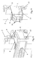
- FIG. 9 shows the detail view FIG. 8 without the cross member 4.
- the profile 10 of the sacrificial part 7 protrudes forward from the region of the side 2 and is geometrically modeled on the rear contour of the cross member 4.
- the bearing 11 can be seen for the cooling module 3 on the back of the side wall 2.
- FIG. 10 shows the back of the side wall 2 in the region of the sacrificial part 7 without cooling module.
- the predetermined breaking points 8 are formed as breaking notches 8 only on the front side of the side wall 2 and thus can not be seen in this illustration on the back.
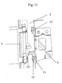
- FIG. 11 shows the detail view FIG. 10 with built-in cooling module.
Landscapes
- Engineering & Computer Science (AREA)
- Chemical & Material Sciences (AREA)
- Combustion & Propulsion (AREA)
- Transportation (AREA)
- Mechanical Engineering (AREA)
- Body Structure For Vehicles (AREA)
- Cooling, Air Intake And Gas Exhaust, And Fuel Tank Arrangements In Propulsion Units (AREA)
- Air-Conditioning For Vehicles (AREA)
Description
- Die Erfindung bezieht sich auf ein Frontendmodul für ein Kraftfahrzeug gemäß Oberbegriff des Anspruchs 1 sowie auf ein Kraftfahrzeug mit einem derartigen Frontendmodul.
- Es ist allgemein bekannt, Kraftfahrzeuge mit Frontendmodulen zu versehen, welche im Falle einer Kollision Energie gezielt so absorbieren, dass funktionelle Bauteile im Frontbereich des Fahrzeugs nicht beschädigt werden. Funktionelle Bauteile im Frontbereich, wie z.B. Kühlmodule etc., sind üblicherweise an Trägerelementen befestigt, die gleichzeitig mit der Karosserie verbunden sind und dabei auch Karosserieteile wie z.B. Stoßfänger, tragen können.
- Im Falle einer Kollision im Frontbereich dringt in der Regel der Stoßfänger mitsamt des Stoßfängerträgers in den Motorraum ein, wobei es insbesondere leicht zur Beschädigung des Kühlmoduls kommen kann. Beim Versicherungscrash (16 km/h) besteht nun die Forderung, dass zumindest das Kühlmodul nicht beschädigt werden darf.
- In der
DE 198 50 590 A1 wird ein Vorbaubereich für ein Kraftfahrzeug beschrieben, bei dem das Kühlmodul an wenigstens zwei Lagerpunkten mit den Trägerelementen des Vorbaubereichs verbunden ist. Dabei sind die wenigstens zwei Lagerpunkte so ausgeführt, dass sie bei einer aufprallbedingten Deformation des Frontendmoduls eine kraftübertragende und kraftaufnehmende Einbindung des Kühlmoduls in die Deformationscharakteristik des Vorbaubereiches bewirken. Diese Anordnung hat den Nachteil, dass der Kühler selber die Kräfte beim Aufprall direkt übernimmt; wodurch es leicht zur Beschädigung des Kühlers kommen kann. - In der
DE 102 60 793 A1 wird eine Crashbox für ein Kraftfahrzeug beschrieben, an der Halterungselemente befestigt sind, an denen wiederum Bauteile, wie z.B. Kühler, angeordnet sein können. Die Crashbox hat die Funktion im Falle einer Kollision die Energie aufzunehmen und zu absorbieren. Der Nachteil dieser Anordnung liegt darin, dass das Kühlmodul direkt mit der Crashbox verbunden ist, so dass es zu Beschädigungen des Kühlmoduls kommt, wenn die Crashbox nicht mehr in der Lage ist, die gesamte Energie des Aufpralls zu absorbieren. - In der
DE 100 51 567 A1 wird eine vordere Endstruktur eines Fahrzeugs beschrieben, bei der der Kühler so an den Trägerelementen des Frontendmoduls befestigt ist, dass er im Falle einer Kollision nach hinten wegklappen kann. Ein Nachteil dieses Klappmechanismus besteht darin, dass relativ viel Platz beansprucht wird, um den Kühler vor einer Beschädigung zu sichern, zudem wird das Trägerelement des Frontendmoduls undefiniert zerstört. - In der
JP-A-10-264856 - Die
EP 1 232 931 A1 , die den Oberbegriff des Anspruchs 1 definiert, beschreibt eine reparaturfreundliche Frontstruktur für ein Kraftfahrzeug, wobei das Kühlmodul so an einem Abschirmblech befestigt ist, dass es im Falle eines Frontalzusammenstoßes nach hinten verschoben und somit geschützt werden kann. Dabei handelt es sich um eine relativ komplizierte Anordnung, bei der eine Vielzahl von Bauteilen aufeinander abgestimmt werden müssen. - Der vorliegenden Erfindung lag deshalb das Problem zugrunde, durch konstruktive Maßnahmen im Bereich des Frontendmoduls eines Kraftfahrzeugs die Energieabsorption im Falle einer Kollision weiter zu verbessern und eine Fahrzeugstruktur zu entwickeln, die die Nachteile des Standes der Technik nicht aufweist und einen verbesserten Schutz des Kühlmoduls gewährleistet.
- Dieses Problem wird bei einem gattungsgemäßen Frontendmodul durch die kennzeichnenden Merkmale des Anspruchs 1 gelöst. Vorteilhafte Ausführungsformen sind Gegenstand der Unteransprüche.
- Die Erfindung basiert auf der Idee, dass ein Bauelement, wie z.B. ein Kühlmodul, im Frontbereich des Kraftfahrzeugs an einem Bereich des Trägerelements befestigt wird, der verschoben werden kann, wenn eine äußere Kraft, die größer ist als ein vorbestimmter Wert, auf diesen Bereich einwirkt. Gleichzeitig bleibt jedoch mindestens ein Befestigungszustand des Bauteils mit dem Trägerelement erhalten, wodurch sichergestellt wird, dass das verschobene Bauteil nicht aus dem Motorraum auf die Straßenfläche fallen kann und dadurch beschädigt wird.
- Erfindungsgemäß wird die Aufgabe dadurch gelöst, dass im Falle einer Kollision der Stoßfänger mitsamt Querträger, der mit einem Deformationselement, z.B. einer als Deformationsprofil ausgeführten Crashbox, an den Seitenwänden des Trägerelements befestigt ist, die Aufprallenergie zunächst über das Deformationselement absorbiert, dabei in den Motorraum eindringt und nach einer definierten Eindringtiefe im Bereich der Seitenwände des Trägerelements auf das Trägerelement selber trifft. Die Seitenwände der Trägerelemente weisen in diesem Bereich einen als Opferteil ausgebildeten Teilbereich auf, der im Kollisionsfall beim Überschreiten eines bestimmten Kraftwertes nach hinten aus dem Gefahrbereich verschoben wird. Da das Kühlmodul im Wesentlichen an diesen Opferteilen gelagert ist und ansonsten leicht lösbar am Trägerelement fixiert ist, wird es zusammen mit den Opferteilen im Motorraum nach hinten verschoben.
- Um diesen Teilbereich verschiebbar zu gestalten, ist der Teilbereich über Sollbruchstellen mit der Seitenwand verbunden und bricht bei Einwirkung einer bestimmten äußeren Kraft heraus. Die Sollbruchstellen sind als Bruchkerben ausgebildet, die in Fahrtrichtung parallel oder sich nach hinten keilförmig öffnend über die gesamte Seitenwand verlaufen.
- Bei einer vorteilhaften Ausführungsform ist die Seitenwand im Bereich des Opferteils geometrisch so ausgebildet, dass in Richtung des Querträgers die hintere Kontur des Querträgers nachgebildet wird; wodurch eine gleichmäßige Krafteinleitung in das Trägerelement gewährleistet wird. Dadurch, dass das Profil vorsteht, wird gleichzeitig verhindert, dass der Querträger bis zum Kühlmodul vordringen und dieses beschädigen kann. Die Befestigung oder Lagerung des Kühlmoduls am Opferteil bleibt auch nach dem Herausbrechen des Opferteils erhalten und das Kühlmodul wird ohne Schaden zu nehmen nach hinten aus dem Aufprallbereich herausgeschoben.
- Neben der Lagerung im Bereich des Opferteils kann das Kühlmodul darüber hinaus an weiteren Stellen des Trägerelements fixiert sein. In einer vorteilhaften Ausführungsform ist das Kühlmodul zusätzlich oberhalb des Opferteils an den Seitenwänden mit Schieberverschlüssen fixiert, die im Falle einer Kollision leicht lösbar sind.
- Die Kraftübertragung auf das Kühlmodul kann durch zusätzliche Rippen, die auf der rückwärtigen Seite des Opferteils neben der Lagerung für das Kühlmodul angebracht sind, optimiert werden.
- Der Querträger ist über ein Deformationselement, das vorzugsweise in Längsrichtung verläuft und einen seitliche Befestigungsmöglichkeiten aufweist, mit den Seitenwänden oberhalb und unterhalb des Opferteils im hinteren Bereich der Seitenwand fest verbunden. Dabei fungiert das Deformationselement gleichzeitig als Halterung für das Unterteil des Trägerelements im Falle eines Crashs, wenn durch Herausbrechen des Opferteils die Verbindung zwischen Unter- und Oberteil des Trägerelements unterbrochen ist. Da das Deformationselement vorzugsweise in Längsrichtung angeordnet ist, kann es im Falle einer Kollision zusammengedrückt werden und dabei den größten Teil der Aufprallenergie absorbieren, bis der Querträger auf die Seitenwand trifft. Überschreitet nun die restliche Energie einen bestimmten Wert, so bricht das Opferteil heraus und die restliche Energie wird über die Opferteile auf das Kühlmodul gelenkt, das dabei, ohne Schaden zu nehmen, nach hinten verschoben wird.
- Mit dem erfindungsgemäßen Frontendmodul gelingt es, den Stossfängerquerträger bei seinem Eindringen in den Motorraum aufzufangen, ohne dass dieser Bauteile im Frontbereich des Kraftfahrzeuges zerstören kann. Die erfindungsgemäße Ausbildung von Opferteilen in den Seitenwänden des Trägerelements erlaubt es, den Platz zwischen Motor und Kühlaggregat weiter zu reduzieren, ohne dabei Gefahr zu laufen, dass das Kühlmodul beim Versicherungscrash (16 km/h) beschädigt wird. Die Erfindung wird nachstehend anhand der in den Figuren dargestellten Ausführungsbeispiele erläutert. Dabei zeigen:
- Figur 1
- eine schematische Darstellung der Vorderansicht des Frontendmoduls ohne Kühlmodul,
- Figur 2
- eine schematische Darstellung der Rückansicht des Frontendmoduls ohne Kühlmodul,
- Figur 3
- eine schematische Ansicht der Rückansicht des Frontendmoduls mit Kühlmodul,
- Figuren 4a und 4b
- eine schematische Darstellung des Frontendmoduls ohne Querträger vor (4a) und nach einem Crash (4b),
- Figuren 5a und 5b
- eine schematische Darstellung des Frontendmoduls mit Träger vor (5a) und nach einem Crash (5b),
- Figuren 6a und 6b
- Eine Horizontal-Schnittdarstellung des Frontend- moduls in einer Ansicht von oben vor (6a) und nach einem Crash (6b),
- Figuren 7a und 7b
- eine Veritkal-Schnittdarstellung des Frontendmo- duls in einer Betrachtungsrichtung von der Seite vor (7a) und nach dem Crash (7b),
- Figur 8
- eine Detailansicht einer Seitenwand mit Querträ- ger,
- Figur 9
- eine Detailansicht einer Seitenwand ohne Quer- träger,
- Figur 10
- eine rückwärtige Detailansicht der Seitenwand ohne Kühlmodul und
- Figur 11
- eine rückwärtige Detailansicht der Seitenwand mit Kühlmodul.
- In der
Figur 1 ist eine schematische Darstellung eines Frontendmoduls in der Vorderansicht zu sehen. Das Frontendmodul besteht im Wesentlichen aus einem Trägerelement 1, das zwei Seitenwände 2 umfasst. Vor dem Trägerelement 1 ist ein Querträger 4 für einen Stossfänger 5 angeordnet, der über eine Crashbox 6, die sich in Längsrichtung an der Außenseite der Seitenwand 2 erstreckt und mit einem seitlichen Flansch 9 im hinteren Bereich mit der Seitenwand 2 oberhalb und unterhalb eines Opferteils 7 verbunden ist. Das Opferteil 7 ist über eine Sollbruchstelle 8 mit dem Seitenteil 2 des Trägerelements 1 verbunden. - Die
Figur 2 zeigt das Frontendmodul ausFigur 1 in einer rückwärtigen Ansicht. In dieser Ansicht ist die Sollbruchstelle 8, die in der vorliegenden Ausführungsform als Bruchkerbe 8 ausgeführt ist, nur in einem kleinen seitlichen Bereich der Seitenwand 2 zu erkennen, da die Bruchkerbe 8 nur einseitig auf der Seitenwand 2 ausgebildet ist. Als zusätzliches Element ist eine Lagerung 11 für das Kühlmodul 3 auf der Rückseite zu erkennen. - Die
Figur 3 zeigt das Frontendmodul ausFigur 2 mit eingebautem Kühlmodul 3. Das Kühlmodul 3 ist im Bereich der Opferteile 7 in der Lagerung 11 gelagert. Zusätzlich ist das Kühlmodul oberhalb des Opferteils 7 mit Schieberverschlüssen 12 fixiert. - Die
Figur 4a zeigt eine schematische Darstellung des Frontendmoduls mit eingebautem Kühler 3, jedoch ohne Querträger 4 im Betriebszustand. Die Seitenwand 2 weist in ihrer Mitte einen durch parallel verlaufende Bruchkerben abgetrennten Teilbereich (Opferteil 7) auf. Oberhalb und unterhalb dieses Opferteils 7 sind im hinteren Bereich der Seitenwand 2 Befestigungsstellen 13 für den seitlichen Flansch 9 der Crashbox 6 des Querträgers 4 zu erkennen. Die Bruchkerben 8 verlaufen parallel über die gesamte Seitenwand 2. Weiterhin erkennt man in dieser Darstellung das aus der Seitenwand 2 herausragende Profil 10 des Opferteils 7, das geometrisch so ausgebildet ist, dass es mit der rückwärtigen Kontur des Querträgers 4 korrespondiert. DieFigur 4b zeigt das Frontendmodul ausFigur 4a nach einem Crash auf der rechten Seite der Motorhaube. Das Opferteil 7 ist zusammen mit dem daran befestigten Kühlmodul 3 durch den Aufprall des Querträgers 4 nach hinten verschoben. - Die
Figuren 5a und 5b zeigen das Frontendmodul aus denFiguren 4a und 4b mit dem Querträger 4. In derFigur 5b ist der Querträger 4 nach einem Crash auf der rechten Seite der Motorhaube in den Bereich der Seitenwand 3 des Trägerelements 1 hineingeschoben und hat dabei das Opferteil 7 zusammen mit dem Kühlmodul 3 nach hinten verschoben. Die Crashbox 6 ist nach der Kollision in sich zusammengedrückt, jedoch wird der Querträger 4 weiterhin mit den seitlichen Flanschen 9 an der Seitenwand 2 festgehalten. - In den
Figuren 6a und 6b ist in einer Schnittzeichnung in der Draufsicht die Situation vor und nach einem Crash zu sehen. - Ebenfalls ist in den
Figuren 7a und 7b diesmal im Querschnitt die Situation vor und nach einem Crash zu sehen. - Die
Figur 8 zeigt in einer Detailansicht die Befestigung des Querträgers 4 an der Seitenwand 2 des Trägerelements 1. Dabei ist der Querträger 4 über die in Längsrichtung verlaufende Crashbox 6, die einen seitlichen Flansch 9 aufweist, an den Befestigungsstellen 13 oberhalb und unterhalb des Opferteils 7 im hinteren Bereich der Seitenwand 2 mit den Trägerelement verbunden. Das Opferteil 7 selber ist über eine Bruchkerbe 8 mit der Seitenwand 2 verbunden. - Die
Figur 9 zeigt die Detailansicht ausFigur 8 ohne den Querträger 4. Das Profil 10 des Opferteils 7 tritt nach vorne aus dem Bereich der Seite 2 heraus und ist geometrisch der rückwärtigen Kontur des Querträgers 4 nachgebildet. In einer Röntgensicht ist die Lagerung 11 für das Kühlmodul 3 auf der Rückseite der Seitenwand 2 zu erkennen. -
Figur 10 zeigt die Rückseite der Seitenwand 2 im Bereich des Opferteils 7 ohne Kühlmodul. Die Sollbruchstellen 8 sind als Bruchkerben 8 lediglich auf der Vorderseite der Seitenwand 2 ausgebildet und somit bei dieser Darstellung auf der Rückseite nicht zu erkennen. -
Figur 11 zeigt die Detailansicht ausFigur 10 mit eingebautem Kühlmodul. - Mit der vorliegenden Erfindung gelingt es, die Crashenergie eines Versicherungscrashs (16 km/h) zu absorbieren, ohne dass dabei das im Frontendmodul integrierte Kühlmodul beschädigt wird, selbst wenn auf Grund von immer kürzer werdenden Fahrzeugüberhängen und immer größerem Platzbedarf durch größere Motoren nur noch wenig Bauraum zur Energieabsorption zur Verfügung steht.
-
- 1
- Trägerelement
- 2
- Seitenwand
- 3
- Kühlmodul
- 4
- Querträger
- 5
- Stossfänger
- 6
- Deformationselement
- 7
- Opferteil
- 8
- Sollbruchstelle
- 9
- seitlicher Flansch
- 10
- Profil
- 11
- Lagerung
- 12
- Schieberverschluss
- 13
- Befestigungsstelle
- 14
- Motor
Claims (8)
- Frontendmodul für ein Kraftfahrzeug mit- einem Trägerelement (1) mit zwei beabstandet voneinander im Wesentlichen vertikal angeordneten Seitenwänden (2),- einem Kühlmodul (3), das im Wesentlichen an den Seitenwänden (2) gelagert ist, und- einem Querträger (4) als Teil eines Stoßfängersystems, wobei- der Querträger (4) jeweils mit einem Deformationselement (6) versehen ist und an den Seitenwänden (2) befestigt ist,- die Seitenwände (2) jeweils einen als Opferteil (7) ausgebildeten Teilbereich (7) aufweisen, der im Kollisionsfall vom Querträger (4) beaufschlagt gegenüber den Seitenwänden (2) verschiebbar ausgebildet ist, und- das Kühlmodul (3) im Wesentlichen an den Opferteilen (7) gelagert ist,dadurch gekennzeichnet, dass das Opferteil (7) über Sollbruchstellen (8) mit der Seitenwand (2) verbunden ist, wobei
die Sollbruchstellen (8) als Bruchkerben (8) ausgebildet sind, wobei
die Bruchkerben (8) in Fahrtrichtung parallel oder keilförmig, sich nach hinten öffnend über die gesamte Seitenwand (2) verlaufen. - Frontendmodul nach Anspruch 1, dadurch gekennzeichnet, dass
das Opferteil (7) auf gleicher Höhe mit dem Querträger (4) angeordnet ist. - Frontendmodul nach Anspruch 1 oder 2,
dadurch gekennzeichnet, dass
das Opferteil (7) in Fahrtrichtung ein Profil (10) aufweist, das mit der rückwärtigen Kontur des Querträgers (4) korrespondiert. - Frontendmodul nach einem der Ansprüche 1 bis 3,
dadurch gekennzeichnet, dass
das Opferteil (7) auf seiner rückwärtigen, zum Kühlermodul gerichteten Seite Abstützelemente zur Kraftübertragung auf die Kühlereinheit aufweist. - Frontendmodul nach einem der Ansprüche 1 bis 4,
dadurch gekennzeichnet, dass
das Deformationselement (6) in Form einer Crashbox (6) in Längsrichtung verläuft und einen seitlichen Flansch (9) aufweist, mit dem der Querträger (4) an den Seitenwänden (2) jeweils oberhalb und unterhalb des Opferteils (7) befestigt ist. - Frontendmodul nach einem der Ansprüche 1 bis 5,
dadurch gekennzeichnet, dass
das Kühlmodul (3) zusätzlich zu den Lagerungen (11) an mindestens einer weiteren Stelle des Trägerelements (1) fixiert ist. - Frontendmodul nach einem der Ansprüche 1 bis 6,
dadurch gekennzeichnet, dass
das Kühlmodul (3) oberhalb des Opferteils (7) an den Seitenwänden (2) mit jeweils einem Schieberverschluss (12) im Kollisionsfall lösbar fixiert ist. - Fahrzeug mit einem Frontendmodul nach einem der Ansprüche 1 bis 7.
Applications Claiming Priority (2)
| Application Number | Priority Date | Filing Date | Title |
|---|---|---|---|
| DE102005058180A DE102005058180A1 (de) | 2005-12-05 | 2005-12-05 | Frontendmodul für ein Kraftfahrzeug mit einer energieabsorbierenden Schutzfunktion für ein Kühlmodul |
| PCT/EP2006/011658 WO2007065629A1 (de) | 2005-12-05 | 2006-12-05 | Frontendmodul für ein kraftfahrzeug mit einer energieabsorbierenden schutzfunktion für ein kühlmodul |
Publications (2)
| Publication Number | Publication Date |
|---|---|
| EP1957346A1 EP1957346A1 (de) | 2008-08-20 |
| EP1957346B1 true EP1957346B1 (de) | 2009-11-25 |
Family
ID=37807782
Family Applications (1)
| Application Number | Title | Priority Date | Filing Date |
|---|---|---|---|
| EP06829302A Not-in-force EP1957346B1 (de) | 2005-12-05 | 2006-12-05 | Frontenmodul für ein kraftfahrzeug mit einer energieabsorbierenden schutzfunktion für ein kühlmodul |
Country Status (5)
| Country | Link |
|---|---|
| EP (1) | EP1957346B1 (de) |
| AT (1) | ATE449721T1 (de) |
| DE (2) | DE102005058180A1 (de) |
| ES (1) | ES2333549T3 (de) |
| WO (1) | WO2007065629A1 (de) |
Cited By (7)
| Publication number | Priority date | Publication date | Assignee | Title |
|---|---|---|---|---|
| DE102013206785A1 (de) * | 2013-04-16 | 2014-10-16 | Ford Global Technologies, Llc | Stoßfängerstruktur für ein Fahrzeug |
| FR3013302A1 (fr) * | 2013-11-19 | 2015-05-22 | Renault Sa | Guide d'air monopiece pour face avant de vehicule automobile et vehicule ainsi equipe |
| DE102016203806A1 (de) | 2015-04-16 | 2016-10-20 | Ford Global Technologies, Llc | Befestigungseinrichtung für ein Kühlmodul |
| DE102018209763A1 (de) | 2018-06-18 | 2019-12-19 | Ford Global Technologies, Llc | Frontendmodul für ein Kraftfahrzeug |
| DE102022124583A1 (de) | 2022-09-26 | 2024-03-28 | Bayerische Motoren Werke Aktiengesellschaft | Lagerung für eine Komponente eines Kraftwagens |
| DE102019106663B4 (de) | 2018-07-16 | 2025-06-18 | Hyundai Motor Company | Frontendmodul |
| US12409722B2 (en) | 2020-04-20 | 2025-09-09 | Valeo Autosystemy Sp. Z O.O. | Service member for a vehicle cooling module and a vehicle cooling module with the service member |
Families Citing this family (13)
| Publication number | Priority date | Publication date | Assignee | Title |
|---|---|---|---|---|
| EP2039592B1 (de) * | 2007-09-21 | 2011-05-25 | Peguform Gmbh | Kraftfahrzeug-Frontendmodul |
| FR2965226B1 (fr) * | 2010-09-24 | 2019-04-19 | Valeo Systemes Thermiques | Dispositif pour le guidage d'un flux d'air pour vehicule automobile et face avant comportant un tel dispositif |
| DE102010043035A1 (de) | 2010-10-28 | 2012-05-03 | Ford-Werke Gmbh | Frontmodul für ein Kraftfahrzeug |
| DE102011002636A1 (de) | 2011-01-13 | 2012-07-19 | Ford Global Technologies, Llc | Frontmodul für ein Kraftfahrzeug |
| DE102011000910A1 (de) | 2011-02-24 | 2012-08-30 | Dr. Ing. H.C. F. Porsche Aktiengesellschaft | Haltevorrichtung |
| FR2978413B1 (fr) | 2011-07-26 | 2014-12-12 | Valeo Systemes Thermiques | Module de face avant de vehicule, notamment vehicule automobile |
| DE102013200073B4 (de) * | 2012-09-03 | 2026-03-19 | Magna International Inc. | Stoßfängerträger |
| DE102012019933A1 (de) * | 2012-10-11 | 2014-04-17 | Volkswagen Aktiengesellschaft | Vorbaustruktur für ein Nutzkraftfahrzeug |
| DE102013010870A1 (de) | 2013-06-28 | 2014-03-27 | Daimler Ag | Halter für ein Anbauteil, insbesondere ein Verkleidungsteil, eines Kraftwagens |
| DE102013012952A1 (de) | 2013-08-02 | 2014-03-06 | Daimler Ag | Fahrzeug |
| DE102013225951A1 (de) | 2013-12-13 | 2015-06-18 | Bayerische Motoren Werke Aktiengesellschaft | Kühlerbaugruppe und Kraftfahrzeug mit einer Kühlerbaugruppe |
| US9840286B2 (en) * | 2016-02-12 | 2017-12-12 | Valeo North America, Inc. | Front end module for a vehicle |
| DE102016112939B4 (de) * | 2016-07-14 | 2023-09-21 | Dr. Ing. H.C. F. Porsche Aktiengesellschaft | Buganordnung für ein Kraftfahrzeug |
Family Cites Families (8)
| Publication number | Priority date | Publication date | Assignee | Title |
|---|---|---|---|---|
| JPH10264856A (ja) * | 1997-03-26 | 1998-10-06 | Aisin Seiki Co Ltd | 車両フロントエンドモジュール構造 |
| DE19850590A1 (de) * | 1998-11-03 | 2000-05-04 | Hella Behr Fahrzeugsysteme | Vorbaubereich für ein Kraftfahrzeug |
| JP3085945B1 (ja) * | 1999-02-24 | 2000-09-11 | 本田技研工業株式会社 | 車両のラジエータ取付け構造 |
| JP4461563B2 (ja) * | 1999-10-20 | 2010-05-12 | 株式会社デンソー | 車両のフロントエンド構造 |
| JP3979016B2 (ja) * | 2001-02-19 | 2007-09-19 | マツダ株式会社 | 自動車の車体前部構造 |
| DE10150643A1 (de) * | 2001-10-12 | 2003-04-17 | Hella Behr Fahrzeugsysteme | Halterung für ein Kraftfahrzeug-Kühlmodul |
| DE10260171B4 (de) * | 2002-12-20 | 2013-06-06 | Volkswagen Ag | Kraftfahrzeug mit wegtauchendem Kühlermodul |
| DE10260793B4 (de) * | 2002-12-23 | 2008-12-11 | Daimler Ag | Crashbox-Kühleraufnahme |
-
2005
- 2005-12-05 DE DE102005058180A patent/DE102005058180A1/de not_active Ceased
-
2006
- 2006-12-05 EP EP06829302A patent/EP1957346B1/de not_active Not-in-force
- 2006-12-05 ES ES06829302T patent/ES2333549T3/es active Active
- 2006-12-05 WO PCT/EP2006/011658 patent/WO2007065629A1/de not_active Ceased
- 2006-12-05 AT AT06829302T patent/ATE449721T1/de not_active IP Right Cessation
- 2006-12-05 DE DE502006005476T patent/DE502006005476D1/de active Active
Cited By (10)
| Publication number | Priority date | Publication date | Assignee | Title |
|---|---|---|---|---|
| DE102013206785A1 (de) * | 2013-04-16 | 2014-10-16 | Ford Global Technologies, Llc | Stoßfängerstruktur für ein Fahrzeug |
| FR3013302A1 (fr) * | 2013-11-19 | 2015-05-22 | Renault Sa | Guide d'air monopiece pour face avant de vehicule automobile et vehicule ainsi equipe |
| WO2015075336A1 (fr) * | 2013-11-19 | 2015-05-28 | Renault | Guide d'air monopièce pour face avant de véhicule automobile et véhicule ainsi équipé |
| CN105829199A (zh) * | 2013-11-19 | 2016-08-03 | 雷诺股份公司 | 用于机动车辆的前端的一件式空气引导件以及配备有一件式空气引导件的车辆 |
| EP3360763A1 (de) * | 2013-11-19 | 2018-08-15 | RENAULT s.a.s. | Einteilige luftführung für frontseite eines kraftfahrzeugs, und damit ausgerüstetes fahrzeug |
| DE102016203806A1 (de) | 2015-04-16 | 2016-10-20 | Ford Global Technologies, Llc | Befestigungseinrichtung für ein Kühlmodul |
| DE102018209763A1 (de) | 2018-06-18 | 2019-12-19 | Ford Global Technologies, Llc | Frontendmodul für ein Kraftfahrzeug |
| DE102019106663B4 (de) | 2018-07-16 | 2025-06-18 | Hyundai Motor Company | Frontendmodul |
| US12409722B2 (en) | 2020-04-20 | 2025-09-09 | Valeo Autosystemy Sp. Z O.O. | Service member for a vehicle cooling module and a vehicle cooling module with the service member |
| DE102022124583A1 (de) | 2022-09-26 | 2024-03-28 | Bayerische Motoren Werke Aktiengesellschaft | Lagerung für eine Komponente eines Kraftwagens |
Also Published As
| Publication number | Publication date |
|---|---|
| ATE449721T1 (de) | 2009-12-15 |
| WO2007065629A8 (de) | 2007-11-08 |
| DE102005058180A1 (de) | 2007-06-06 |
| EP1957346A1 (de) | 2008-08-20 |
| WO2007065629A1 (de) | 2007-06-14 |
| ES2333549T3 (es) | 2010-02-23 |
| DE502006005476D1 (de) | 2010-01-07 |
Similar Documents
| Publication | Publication Date | Title |
|---|---|---|
| DE60303274T2 (de) | Kraftfahrzeugscheinwerfer mit verbesserten Verbindungsmitteln zum Fahrgestell | |
| EP1957346A1 (de) | Frontenmodul für ein kraftfahrzeug mit einer energieabsorbierenden schutzfunktion für ein kühlmodul | |
| DE102013102501B4 (de) | Kraftfahrzeug | |
| DE102015112506A1 (de) | Frontendmodul | |
| EP2447101B1 (de) | Frontmodul für ein Kraftfahrzeug | |
| DE19851495A1 (de) | Tragstruktur eines Vorderwagens eines Kraftfahrzeugs | |
| EP2156992A1 (de) | Crashoptimiertes Frontendmodul für ein Fahrzeug | |
| DE102022126585B3 (de) | Energiespeicher-Bodenanlage für einen elektrisch antreibbaren Kraftwagen | |
| DE102021215080A1 (de) | Optimierte Fahrzeughaube für Aufprallschutz | |
| DE102014205223A1 (de) | Anordnung in einem Kraftfahrzeugvorderwagen zum Schutz einer Kühlerbaugruppe sowie Kühler-Lagerelement für eine solche Anordnung | |
| DE102015110436B3 (de) | Kraftfahrzeug | |
| DE102021114902B4 (de) | Fahrzeug mit Bodenbaugruppe | |
| EP2548786B1 (de) | Anbindung eines Anbauelements an einem Nutzfahrzeugrahmen | |
| DE102016013877A1 (de) | Stützanordnung für einen Stoßfänger eines Kraftwagens | |
| DE102006059028B4 (de) | Trageinrichtung für ein Frontend eines Personenkraftwagens | |
| DE10142796B4 (de) | Frontbereich eines Kraftfahrzeuges und Pralleinheit hierfür | |
| DE102023110205A1 (de) | Fahrgestellrahmen eines Fahrzeugs | |
| DE102005053778A1 (de) | Crashbox | |
| DE102014225019B4 (de) | Anordnung zum Schutz eines Antriebsenergiespeichers eines Kraftfahrzeuges | |
| WO2012113430A1 (de) | Anordnung einer stossfängereinrichtung vor einer kühlereinrichtung eines kraftwagens | |
| DE10235879B3 (de) | Motorlagerung mit veränderbarer Bauhöhe | |
| DE102006030505B4 (de) | Vorrichtung zur Verbindung eines Stoßfängerüberzugs mit einer Karosserie | |
| DE102009040341A1 (de) | Unterfahrschutzeinrichtung für ein Nutzfahrzeug | |
| DE102016009392B4 (de) | Kraftwagen mit einer Stoßfängeranordnung | |
| DE102015015476B3 (de) | Crashstruktur für ein Fahrzeug |
Legal Events
| Date | Code | Title | Description |
|---|---|---|---|
| PUAI | Public reference made under article 153(3) epc to a published international application that has entered the european phase |
Free format text: ORIGINAL CODE: 0009012 |
|
| 17P | Request for examination filed |
Effective date: 20080331 |
|
| AK | Designated contracting states |
Kind code of ref document: A1 Designated state(s): AT BE BG CH CY CZ DE DK EE ES FI FR GB GR HU IE IS IT LI LT LU LV MC NL PL PT RO SE SI SK TR |
|
| 17Q | First examination report despatched |
Effective date: 20080922 |
|
| RIN1 | Information on inventor provided before grant (corrected) |
Inventor name: BREISACHER, MICHAEL Inventor name: RINDERLIN, JUERGEN |
|
| GRAP | Despatch of communication of intention to grant a patent |
Free format text: ORIGINAL CODE: EPIDOSNIGR1 |
|
| GRAS | Grant fee paid |
Free format text: ORIGINAL CODE: EPIDOSNIGR3 |
|
| GRAA | (expected) grant |
Free format text: ORIGINAL CODE: 0009210 |
|
| AK | Designated contracting states |
Kind code of ref document: B1 Designated state(s): AT BE BG CH CY CZ DE DK EE ES FI FR GB GR HU IE IS IT LI LT LU LV MC NL PL PT RO SE SI SK TR |
|
| REG | Reference to a national code |
Ref country code: GB Ref legal event code: FG4D Free format text: NOT ENGLISH |
|
| REG | Reference to a national code |
Ref country code: CH Ref legal event code: EP |
|
| REG | Reference to a national code |
Ref country code: IE Ref legal event code: FG4D |
|
| REF | Corresponds to: |
Ref document number: 502006005476 Country of ref document: DE Date of ref document: 20100107 Kind code of ref document: P |
|
| REG | Reference to a national code |
Ref country code: NL Ref legal event code: VDEP Effective date: 20091125 |
|
| LTIE | Lt: invalidation of european patent or patent extension |
Effective date: 20091125 |
|
| PG25 | Lapsed in a contracting state [announced via postgrant information from national office to epo] |
Ref country code: PT Free format text: LAPSE BECAUSE OF FAILURE TO SUBMIT A TRANSLATION OF THE DESCRIPTION OR TO PAY THE FEE WITHIN THE PRESCRIBED TIME-LIMIT Effective date: 20100325 Ref country code: IS Free format text: LAPSE BECAUSE OF FAILURE TO SUBMIT A TRANSLATION OF THE DESCRIPTION OR TO PAY THE FEE WITHIN THE PRESCRIBED TIME-LIMIT Effective date: 20100325 Ref country code: FI Free format text: LAPSE BECAUSE OF FAILURE TO SUBMIT A TRANSLATION OF THE DESCRIPTION OR TO PAY THE FEE WITHIN THE PRESCRIBED TIME-LIMIT Effective date: 20091125 Ref country code: LT Free format text: LAPSE BECAUSE OF FAILURE TO SUBMIT A TRANSLATION OF THE DESCRIPTION OR TO PAY THE FEE WITHIN THE PRESCRIBED TIME-LIMIT Effective date: 20091125 Ref country code: SE Free format text: LAPSE BECAUSE OF FAILURE TO SUBMIT A TRANSLATION OF THE DESCRIPTION OR TO PAY THE FEE WITHIN THE PRESCRIBED TIME-LIMIT Effective date: 20091125 |
|
| PG25 | Lapsed in a contracting state [announced via postgrant information from national office to epo] |
Ref country code: LV Free format text: LAPSE BECAUSE OF FAILURE TO SUBMIT A TRANSLATION OF THE DESCRIPTION OR TO PAY THE FEE WITHIN THE PRESCRIBED TIME-LIMIT Effective date: 20091125 Ref country code: CY Free format text: LAPSE BECAUSE OF FAILURE TO SUBMIT A TRANSLATION OF THE DESCRIPTION OR TO PAY THE FEE WITHIN THE PRESCRIBED TIME-LIMIT Effective date: 20091125 Ref country code: PL Free format text: LAPSE BECAUSE OF FAILURE TO SUBMIT A TRANSLATION OF THE DESCRIPTION OR TO PAY THE FEE WITHIN THE PRESCRIBED TIME-LIMIT Effective date: 20091125 Ref country code: SI Free format text: LAPSE BECAUSE OF FAILURE TO SUBMIT A TRANSLATION OF THE DESCRIPTION OR TO PAY THE FEE WITHIN THE PRESCRIBED TIME-LIMIT Effective date: 20091125 |
|
| REG | Reference to a national code |
Ref country code: IE Ref legal event code: FD4D |
|
| BERE | Be: lapsed |
Owner name: PEGUFORM G.M.B.H. Effective date: 20091231 |
|
| PG25 | Lapsed in a contracting state [announced via postgrant information from national office to epo] |
Ref country code: RO Free format text: LAPSE BECAUSE OF FAILURE TO SUBMIT A TRANSLATION OF THE DESCRIPTION OR TO PAY THE FEE WITHIN THE PRESCRIBED TIME-LIMIT Effective date: 20091125 Ref country code: NL Free format text: LAPSE BECAUSE OF FAILURE TO SUBMIT A TRANSLATION OF THE DESCRIPTION OR TO PAY THE FEE WITHIN THE PRESCRIBED TIME-LIMIT Effective date: 20091125 Ref country code: MC Free format text: LAPSE BECAUSE OF NON-PAYMENT OF DUE FEES Effective date: 20100701 Ref country code: EE Free format text: LAPSE BECAUSE OF FAILURE TO SUBMIT A TRANSLATION OF THE DESCRIPTION OR TO PAY THE FEE WITHIN THE PRESCRIBED TIME-LIMIT Effective date: 20091125 Ref country code: DK Free format text: LAPSE BECAUSE OF FAILURE TO SUBMIT A TRANSLATION OF THE DESCRIPTION OR TO PAY THE FEE WITHIN THE PRESCRIBED TIME-LIMIT Effective date: 20091125 Ref country code: BG Free format text: LAPSE BECAUSE OF FAILURE TO SUBMIT A TRANSLATION OF THE DESCRIPTION OR TO PAY THE FEE WITHIN THE PRESCRIBED TIME-LIMIT Effective date: 20100225 Ref country code: IE Free format text: LAPSE BECAUSE OF FAILURE TO SUBMIT A TRANSLATION OF THE DESCRIPTION OR TO PAY THE FEE WITHIN THE PRESCRIBED TIME-LIMIT Effective date: 20091125 |
|
| PG25 | Lapsed in a contracting state [announced via postgrant information from national office to epo] |
Ref country code: CZ Free format text: LAPSE BECAUSE OF FAILURE TO SUBMIT A TRANSLATION OF THE DESCRIPTION OR TO PAY THE FEE WITHIN THE PRESCRIBED TIME-LIMIT Effective date: 20091125 Ref country code: SK Free format text: LAPSE BECAUSE OF FAILURE TO SUBMIT A TRANSLATION OF THE DESCRIPTION OR TO PAY THE FEE WITHIN THE PRESCRIBED TIME-LIMIT Effective date: 20091125 |
|
| PLBE | No opposition filed within time limit |
Free format text: ORIGINAL CODE: 0009261 |
|
| STAA | Information on the status of an ep patent application or granted ep patent |
Free format text: STATUS: NO OPPOSITION FILED WITHIN TIME LIMIT |
|
| PG25 | Lapsed in a contracting state [announced via postgrant information from national office to epo] |
Ref country code: GR Free format text: LAPSE BECAUSE OF FAILURE TO SUBMIT A TRANSLATION OF THE DESCRIPTION OR TO PAY THE FEE WITHIN THE PRESCRIBED TIME-LIMIT Effective date: 20100226 Ref country code: BE Free format text: LAPSE BECAUSE OF NON-PAYMENT OF DUE FEES Effective date: 20091231 |
|
| 26N | No opposition filed |
Effective date: 20100826 |
|
| PG25 | Lapsed in a contracting state [announced via postgrant information from national office to epo] |
Ref country code: LU Free format text: LAPSE BECAUSE OF NON-PAYMENT OF DUE FEES Effective date: 20091205 |
|
| PG25 | Lapsed in a contracting state [announced via postgrant information from national office to epo] |
Ref country code: AT Free format text: LAPSE BECAUSE OF NON-PAYMENT OF DUE FEES Effective date: 20091205 |
|
| PGRI | Patent reinstated in contracting state [announced from national office to epo] |
Ref country code: IT Effective date: 20110501 |
|
| PG25 | Lapsed in a contracting state [announced via postgrant information from national office to epo] |
Ref country code: HU Free format text: LAPSE BECAUSE OF FAILURE TO SUBMIT A TRANSLATION OF THE DESCRIPTION OR TO PAY THE FEE WITHIN THE PRESCRIBED TIME-LIMIT Effective date: 20100526 |
|
| REG | Reference to a national code |
Ref country code: CH Ref legal event code: PL |
|
| GBPC | Gb: european patent ceased through non-payment of renewal fee |
Effective date: 20101205 |
|
| PG25 | Lapsed in a contracting state [announced via postgrant information from national office to epo] |
Ref country code: TR Free format text: LAPSE BECAUSE OF FAILURE TO SUBMIT A TRANSLATION OF THE DESCRIPTION OR TO PAY THE FEE WITHIN THE PRESCRIBED TIME-LIMIT Effective date: 20091125 |
|
| PG25 | Lapsed in a contracting state [announced via postgrant information from national office to epo] |
Ref country code: LI Free format text: LAPSE BECAUSE OF NON-PAYMENT OF DUE FEES Effective date: 20101231 Ref country code: CH Free format text: LAPSE BECAUSE OF NON-PAYMENT OF DUE FEES Effective date: 20101231 |
|
| PG25 | Lapsed in a contracting state [announced via postgrant information from national office to epo] |
Ref country code: GB Free format text: LAPSE BECAUSE OF NON-PAYMENT OF DUE FEES Effective date: 20101205 |
|
| REG | Reference to a national code |
Ref country code: FR Ref legal event code: PLFP Year of fee payment: 10 |
|
| REG | Reference to a national code |
Ref country code: FR Ref legal event code: PLFP Year of fee payment: 11 |
|
| PGFP | Annual fee paid to national office [announced via postgrant information from national office to epo] |
Ref country code: IT Payment date: 20161220 Year of fee payment: 11 Ref country code: ES Payment date: 20161221 Year of fee payment: 11 Ref country code: FR Payment date: 20161221 Year of fee payment: 11 |
|
| REG | Reference to a national code |
Ref country code: FR Ref legal event code: ST Effective date: 20180831 |
|
| PG25 | Lapsed in a contracting state [announced via postgrant information from national office to epo] |
Ref country code: IT Free format text: LAPSE BECAUSE OF NON-PAYMENT OF DUE FEES Effective date: 20171205 Ref country code: FR Free format text: LAPSE BECAUSE OF NON-PAYMENT OF DUE FEES Effective date: 20180102 |
|
| PGFP | Annual fee paid to national office [announced via postgrant information from national office to epo] |
Ref country code: DE Payment date: 20181220 Year of fee payment: 13 |
|
| REG | Reference to a national code |
Ref country code: ES Ref legal event code: FD2A Effective date: 20190702 |
|
| PG25 | Lapsed in a contracting state [announced via postgrant information from national office to epo] |
Ref country code: ES Free format text: LAPSE BECAUSE OF NON-PAYMENT OF DUE FEES Effective date: 20171206 |
|
| REG | Reference to a national code |
Ref country code: DE Ref legal event code: R119 Ref document number: 502006005476 Country of ref document: DE |
|
| PG25 | Lapsed in a contracting state [announced via postgrant information from national office to epo] |
Ref country code: DE Free format text: LAPSE BECAUSE OF NON-PAYMENT OF DUE FEES Effective date: 20200701 |