EP1955761A1 - Mischgranulator - Google Patents
Mischgranulator Download PDFInfo
- Publication number
- EP1955761A1 EP1955761A1 EP07033523A EP07033523A EP1955761A1 EP 1955761 A1 EP1955761 A1 EP 1955761A1 EP 07033523 A EP07033523 A EP 07033523A EP 07033523 A EP07033523 A EP 07033523A EP 1955761 A1 EP1955761 A1 EP 1955761A1
- Authority
- EP
- European Patent Office
- Prior art keywords
- mixing
- outlet opening
- granulator according
- mixing container
- curved
- Prior art date
- Legal status (The legal status is an assumption and is not a legal conclusion. Google has not performed a legal analysis and makes no representation as to the accuracy of the status listed.)
- Granted
Links
Images


Classifications
-
- B—PERFORMING OPERATIONS; TRANSPORTING
- B01—PHYSICAL OR CHEMICAL PROCESSES OR APPARATUS IN GENERAL
- B01J—CHEMICAL OR PHYSICAL PROCESSES, e.g. CATALYSIS OR COLLOID CHEMISTRY; THEIR RELEVANT APPARATUS
- B01J2/00—Processes or devices for granulating materials, e.g. fertilisers in general; Rendering particulate materials free flowing in general, e.g. making them hydrophobic
- B01J2/10—Processes or devices for granulating materials, e.g. fertilisers in general; Rendering particulate materials free flowing in general, e.g. making them hydrophobic in stationary drums or troughs, provided with kneading or mixing appliances
-
- B—PERFORMING OPERATIONS; TRANSPORTING
- B01—PHYSICAL OR CHEMICAL PROCESSES OR APPARATUS IN GENERAL
- B01F—MIXING, e.g. DISSOLVING, EMULSIFYING OR DISPERSING
- B01F27/00—Mixers with rotary stirring devices in fixed receptacles; Kneaders
- B01F27/05—Stirrers
- B01F27/09—Stirrers characterised by the mounting of the stirrers with respect to the receptacle
- B01F27/091—Stirrers characterised by the mounting of the stirrers with respect to the receptacle with elements co-operating with receptacle wall or bottom, e.g. for scraping the receptacle wall
-
- B—PERFORMING OPERATIONS; TRANSPORTING
- B01—PHYSICAL OR CHEMICAL PROCESSES OR APPARATUS IN GENERAL
- B01F—MIXING, e.g. DISSOLVING, EMULSIFYING OR DISPERSING
- B01F27/00—Mixers with rotary stirring devices in fixed receptacles; Kneaders
- B01F27/05—Stirrers
- B01F27/11—Stirrers characterised by the configuration of the stirrers
- B01F27/112—Stirrers characterised by the configuration of the stirrers with arms, paddles, vanes or blades
- B01F27/1123—Stirrers characterised by the configuration of the stirrers with arms, paddles, vanes or blades sickle-shaped, i.e. curved in at least one direction
-
- B—PERFORMING OPERATIONS; TRANSPORTING
- B01—PHYSICAL OR CHEMICAL PROCESSES OR APPARATUS IN GENERAL
- B01F—MIXING, e.g. DISSOLVING, EMULSIFYING OR DISPERSING
- B01F27/00—Mixers with rotary stirring devices in fixed receptacles; Kneaders
- B01F27/05—Stirrers
- B01F27/11—Stirrers characterised by the configuration of the stirrers
- B01F27/112—Stirrers characterised by the configuration of the stirrers with arms, paddles, vanes or blades
- B01F27/1122—Stirrers characterised by the configuration of the stirrers with arms, paddles, vanes or blades anchor-shaped
Definitions
- the invention relates to a mixing granulator having a curved bottom having a mixing container and adapted to the curved bottom mixing tools, which are supported and driven by a vertically oriented drive shaft.
- a mixed granulator which is designed as a batch mixer and having at its bottom side a discharge opening through which the mix is discharged.
- mixing tools are provided in the mixing vessel, on the one hand enable a good mixing of the mixed material, on the other hand cause by reversal of the direction of rotation of the agitator discharge of the mix from a arranged in the bottom discharge opening.
- a valve is used to open the actual mixing container, which is filled to a large filling level, with the larger part of the container contents being discharged during the batchwise emptying, while a remainder remains in the lower region of the container, so that there is always a bed of already solidified free-flowing material is maintained.
- the invention has for its object to provide a mixing granulator, with which a continuous mixing and granulation of the mix is possible, ie it is not provided batchwise dispensing of granulated material, but the device according to the invention should operate continuously, ie the material to be mixed is fed continuously and continuously, the obtained granules are removed and fed, for example, a drying device.
- the bottom is designed to be closed, but nevertheless arched, and the agitator or the mixing tools are curved in conformity with the curvature of the bottom, so that When operating the mixing tool no centrifugal forces occur, but a good mixing and granulation of the filled material is done.
- the actual mixing container has at its side wall region an outlet opening, which is set at a maximum so that the lower edge of the outlet opening is aligned at most with the upper edge of the stirring tool.
- the upper edge of the stirring tool is provided below the lower edge of the outlet opening.
- liquid and solid addition devices are provided, which continuously fill the material to be mixed and granulated into the container, wherein a continuous discharge of the finished mixed and granulated material takes place through an outlet opening in the wall region.
- the actual outlet opening has a regulating flap regulating the size of the outlet opening.
- This auxiliary device can be combined with a comminution device, but can also be designed as a normal agitating blade, wherein preferably the direction of rotation of the actual mixing and granulating tool is adjusted counter to the direction of rotation of this discharge device.
- a sieve insert may be provided.
- 1 denotes a mixing granulator which is formed from a mixing container 2 having a curved bottom 5.
- this mixing container 2 performs a drive shaft 3, which carries at its lower end the actual stirring and mixing tool 4, which, as this is particularly clear
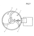
- Fig. 7 shows three wings 12, 14 and 15, which are formed in adaptation to the curved bottom 5.
- This mixing tool 4 is driven in the direction of the arrow F1.
- the mixing container 2 In the upper region of the mixing container 2 is provided in the adding device 6, 7 for liquids and solid, which are mixed and granulated according to their entry through the mixing and stirring tool 4.
- an outlet opening is shown in the wall of the mixing container 2, which leads via a corresponding guide device 19 to a drying device 18.
- a regulating flap 11 is adjustably provided, so that thereby the height of the lower edge of the outlet opening 8 can be adjusted.
- a sieve insert 10 may be provided, are retained by the possibly too large granules.
- an auxiliary device 9 is provided, which allows a ZuANCn the Granuliergutes the outlet opening 8, but at the same time can also be combined with a crushing device 16.
- This device is preferably driven in the direction of the arrow F2, i. H. the direction of rotation of this auxiliary device 9 is opposite to the direction of rotation of the mixing tool 4, whereby a good discharging and discharging the granulated material is achieved.
- the discharge device 9 is provided without crushing tools, while in the embodiment according to Fig. 4 a corresponding combination between discharge 9 and crushing device 16 is provided.
- a corresponding combination between discharge 9 and crushing device 16 is provided in the embodiment according to Fig. 5 only crushing tools 16 are provided and in the embodiment according to Fig. 6 an agitator blade 17 is provided which allows a good discharge of the goods.
- the actual wings 12, 14 and 15 of the stirring tool 4 are shown as if they rest on the bottom 5 of the mixing container 1. It is of course possible that between the lower edge of the tools and the bottom 5 of the mixing container 1, a small free space is available, which is cleared, for example, of one of the wings 12, 14 or 15.
- auxiliary device 9 can also be designed as a normal paddle. As already stated, it makes sense that the upper edge of the wings 12, 14 and 15 of the mixing tool 4 maximum to the lower edge of the outlet opening 8, wherein in the drawings, but here also a distance is shown, which is then bridged by the auxiliary tool 9.
Landscapes
- Chemical & Material Sciences (AREA)
- Chemical Kinetics & Catalysis (AREA)
- Organic Chemistry (AREA)
- Mixers Of The Rotary Stirring Type (AREA)
- Apparatuses For Bulk Treatment Of Fruits And Vegetables And Apparatuses For Preparing Feeds (AREA)
Abstract
Description
- Die Erfindung bezieht sich auf einen Mischgranulator mit einem einen gewölbt ausgebildeten Boden aufweisenden Mischbehälter und in Anpassung an den gewölbten Boden ausgebildete Mischwerkzeuge, die von einer vertikal ausgerichteten Antriebswelle getragen und angetrieben werden.
- In der gattungsbildenden
EP 0 439 689 B1 wird ein Mischgranulator beschrieben, der als Chargenmischer ausgebildet ist und der an seiner Bodenseite eine Austragsöffnung aufweist, durch die das Mischgut ausgetragen wird. Hierbei sind in dem Mischbehälter Rührwerkzeuge vorgesehen, die einerseits ein gutes Mischen des Mischgutes ermöglichen, andererseits durch Umkehr der Umlaufrichtung des Rührwerkes ein Austragen des Mischgutes aus einer im Boden angeordneten Austragsöffnung bewirken. Durch diese Anordnung wird also eine chargenweise Granulation und Entleerung des Mischgutes herbeigeführt, was immer wieder zur Unterbrechung des eigentlichen Mischvorganges führt. - Aus der
JP 2000-354 753 A JP 61178031 A - Das Gleiche gilt für die Einrichtung gemäß der schweizerischen Patentschrift
632 939 - Der Erfindung liegt die Aufgabe zugrunde, einen Mischgranulator vorzuschlagen, mit dem ein kontinuierliches Mischen und Granulieren des Mischgutes möglich ist, d. h. es wird kein chargenweises Abgeben des granulierten Gutes vorgesehen, sondern die erfindungsgemäße Vorrichtung soll kontinuierlich arbeiten, d. h. das zu mischende Gut wird kontinuierlich zugeführt und kontinuierlich wird das erzielte Granulat abgeführt und beispielsweise einer Trocknungsvorrichtung zugeführt.
- Diese der Erfindung zugrundeliegende Aufgabe wird durch die Lehre des Hauptanspruches gelöst.
- Vorteilhafte Ausführungsformen sind in den Unteransprüchen erläutert.
- So wird mit anderen Worten ausgedrückt gemäß der Erfindung vorgeschlagen, dass im Gegensatz zum gattungsbildenden Stand der Technik der Boden geschlossen ausgebildet ist, aber trotzdem gewölbt gestaltet ist und auch das Rührwerk oder die Mischwerkzeuge in Anpassung an die Wölbung des Bodens gewölbt gestaltet sind, so dass beim Betrieb des Mischwerkzeuges keine Zentrifugalkräfte auftreten, sondern ein gutes Mischen und damit Granulieren des eingefüllten Gutes erfolgt.
- Der eigentliche Mischbehälter weist an seinem Seitenwandbereich eine Auslauföffnung auf, die maximal so eingestellt ist, dass die Unterkante der Auslauföffnung maximal mit der Oberkante des Rührwerkzeuges fluchtet. Vorzugsweise ist aber die Oberkante des Rührwerkzeuges unterhalb der unteren Kante der Auslauföffnung vorgesehen.
- Schließlich sind Zugabevorrichtungen für Flüssigkeit und Feststoff vorgesehen, die kontinuierlich das zu mischende und zu granulierende Gut in den Behälter einfüllen, wobei ein kontinuierlicher Austrag des fertig gemischten und granulierten Gutes durch eine Auslauföffnung im Wandbereich erfolgt.
- Um die Auslauföffnung an unterschiedliche Mischgüter einzustellen, wird gemäß einem Merkmal der Erfindung vorgeschlagen, dass die eigentliche Auslauföffnung eine die Größe der Auslauföffnung regulierende Regulierklappe aufweist.
- Gemäß einem weiteren wesentlichen Merkmal der Erfindung ist vorgesehen, dass innerhalb des eigentlichen Mischbehälters und vor der Auslauföffnung eine den Austrag des Misch- und Granuliergutes unterstützende Hilfsvorrichtung vorgesehen ist.
- Diese Hilfsvorrichtung kann mit einer Zerkleinerungsvorrichtung kombiniert sein, kann aber auch als normaler Rührflügel ausgebildet sein, wobei vorzugsweise die Umlaufrichtung des eigentlichen Misch- und Granulierwerkzeuges entgegen der Umlaufrichtung dieser Austragsvorrichtung eingestellt wird.
- In der eigentlichen Auslauföffnung oder vor der Auslauföffnung kann ein Siebeinsatz vorgesehen sein.
- Ein Ausführungsbeispiel der Erfindung wird nachfolgend anhand der Zeichnungen erläutert. Die Zeichnungen zeigen dabei in
- Fig. 1
- eine Gesamtansicht geschnitten auf den erfindungsgemäß ausgebildeten Mischgranulator, in
- Fig. 2
- eine Teilansicht auf die Austragsvorrichtung, in
- Fig. 3
- ebenfalls eine Teilansicht auf eine abgewandelte Ausführungsform der Austragsvorrichtung, in
- Fig. 4
- ebenfalls eine Teilansicht auf eine abgewandelte Ausführungsform der Austragsvorrichtung, in
- Fig. 5
- eine Teilansicht auf eine wiederum abgewandelte Ausführungsform der Austragsvorrichtung, in
- Fig. 6
- eine Teilansicht auf eine abgewandelte Ausführungsform der Austragsvorrichtung und schließlich in
- Fig. 7
- eine Draufsicht auf die erfindungsgemäße Anordnung.
- In den Zeichnungen ist mit 1 ein Mischgranulator bezeichnet, der aus einem Mischbehälter 2 gebildet wird, der einen gewölbten Boden 5 aufweist. In diesen Mischbehälter 2 führt eine Antriebswelle 3, die an ihrem unteren Ende das eigentliche Rühr- und Mischwerkzeug 4 trägt, das, wie dies besonders deutlich
Fig. 7 zeigt, drei Flügel 12, 14 und 15 aufweist, die in Anpassung an den gewölbten Boden 5 ausgebildet sind. Dieses Mischwerkzeug 4 wird in Richtung des Pfeiles F1 angetrieben. - Im oberen Bereich des Mischbehälters 2 ist in der Zugabevorrichtung 6, 7 für Flüssigkeiten und Feststoff vorgesehen, die nach ihrem Eintrag durch das Misch- und Rührwerkzeug 4 entsprechend gemischt und granuliert werden.
- Bei 8 ist in der Wandung des Mischbehälters 2 eine Auslauföffnung dargestellt, die über eine entsprechende Leitvorrichtung 19 zu einer Trocknungsvorrichtung 18 führt. Vor der Auslauföffnung 8 ist eine Regulierklappe 11 einstellbar vorgesehen, so dass dadurch die Höhe der Unterkante der Auslauföffnung 8 eingestellt werden kann.
- Wie dies
Fig. 2 zeigt, kann in der Auslauföffnung 8 ein Siebeinsatz 10 vorgesehen sein, durch den ggf. zu große Granulate zurückgehalten werden. - Vor der Auslauföffnung 8 innerhalb des Mischbehälters 2 ist eine Hilfsvorrichtung 9 vorgesehen, die ein Zufördern des Granuliergutes zur Auslauföffnung 8 ermöglicht, gleichzeitig aber auch mit einer Zerkleinerungsvorrichtung 16 kombiniert sein kann. Diese Vorrichtung wird vorzugsweise in Richtung des Pfeiles F2 angetrieben, d. h. die Umlaufrichtung dieser Hilfseinrichtung 9 ist entgegengesetzt der Umlaufrichtung des Mischwerkzeuges 4, wodurch ein gutes Austragen und Abfördern des granulierten Gutes erreicht wird.
- Bei der Ausführungsform gemäß
Fig. 3 ist die Austragsvorrichtung 9 ohne Zerkleinerungswerkzeuge vorgesehen, während bei der Ausführungsform gemäßFig. 4 eine entsprechende Kombination zwischen Austragsvorrichtung 9 und Zerkleinerungsvorrichtung 16 vorgesehen ist. Bei der Ausführungsform gemäßFig. 5 sind lediglich Zerkleinerungswerkzeuge 16 vorgesehen und bei der Ausführungsform gemäßFig. 6 ist ein Rührflügel 17 vorgesehen, der ein gutes Abfördern des Gutes ermöglicht. - In der Zeichnung sind die eigentlichen Flügel 12, 14 und 15 des Rührwerkzeuges 4 so dargestellt, als ob sie auf dem Boden 5 des Mischbehälters 1 aufliegen. Es ist selbstverständlich möglich, dass zwischen der Unterkante der Werkzeuge und dem Boden 5 des Mischbehälters 1 auch ein kleiner Freiraum vorhanden ist, der beispielsweise von einem der Flügel 12, 14 oder 15 freigeräumt wird.
- Auch zeigt die
Fig. 7 , dass die Hilfsvorrichtung 9 auch als normales Paddel ausgebildet sein kann. Wie bereits ausgeführt, erscheint es sinnvoll, dass die Oberkante der Flügel 12, 14 und 15 des Mischwerkzeuges 4 maximal bis zur Unterkante der Auslauföffnung 8 reicht, wobei in den Zeichnungen, aber hier auch noch eine Distanz dargestellt ist, die dann von dem Hilfswerkzeug 9 überbrückt wird.
Claims (9)
- Mischgranulator mit einem Mischbehälter und einem darin befindlichen, eine vertikal ausgerichtete Antriebswelle aufweisenden Rührwerk, bei dem der Mischbehälter an seiner Bodenseite gewölbt ausgebildet ist und in Anpassung an den gewölbten Boden gewölbt ausgebildete Mischwerkzeuge vorgesehen sind, dadurch gekennzeichnet,a) dass der Boden (5) geschlossen ausgebildet ist,b) der Mischbehälter (2) im Wandbereich eine Auslauföffnung (8) aufweist, die maximal so eingestellt ist, dass die Unterkante der Auslauföffnung (8) maximal mit der Oberkante des Rührwerkzeuges (4) fluchtet undc) Zugabevorrichtungen (6, 7) für Flüssigkeit und Feststoffe in den eigentlichen Mischbehälter (2) vorgesehen sind.
- Mischgranulator nach Anspruch 1, dadurch gekennzeichnet, dass die Oberkante des Rührwerkzeuges (4) unterhalb der unteren Kante der Auslauföffnung (8) liegt.
- Mischgranulator nach Anspruch 1 oder 2, dadurch gekennzeichnet, dass innerhalb des Mischbehälters (2) vor der Auslauföffnung (8) eine den Austrag des Misch- und Granuliergutes unterstützende Hilfsvorrichtung (9) vorgesehen ist.
- Mischgranulator nach Anspruch 3, dadurch gekennzeichnet, dass die Hilfsvorrichtung (9) mit einer Zerkleinerungsvorrichtung (16) kombiniert ist.
- Mischgranulator nach einem oder mehreren der vorhergehenden Ansprüche, dadurch gekennzeichnet, dass die Hilfsvorrichtung (9) als Rührflügel (17) ausgebildet ist.
- Mischgranulator nach einem oder mehreren der vorhergehenden Ansprüche, dadurch gekennzeichnet, dass die Auslauföffnung (8) eine die Größe der Öffnung regulierende Regulierklappe (11) aufweist.
- Mischgranulator nach einem oder mehreren der vorhergehenden Ansprüche, dadurch gekennzeichnet, dass vor oder innerhalb der Auslauföffnung (8) ein Siebeinsatz (10) vorgesehen ist.
- Mischgranulator nach einem oder mehreren der vorhergehenden Ansprüche, dadurch gekennzeichnet, dass an die Auslauföffnung (8) eine Trocknungseinrichtung (18) anschließt.
- Mischgranulator nach einem oder mehreren der vorhergehenden Ansprüche, dadurch gekennzeichnet, dass die Umlaufrichtung F1 des Mischwerkzeuges (4) entgegengesetzt der Umlaufrichtung F2 der Austragsvorrichtung (9) ist.
Applications Claiming Priority (1)
| Application Number | Priority Date | Filing Date | Title |
|---|---|---|---|
| DE102007006024A DE102007006024A1 (de) | 2007-02-07 | 2007-02-07 | Mischgranulator |
Publications (2)
| Publication Number | Publication Date |
|---|---|
| EP1955761A1 true EP1955761A1 (de) | 2008-08-13 |
| EP1955761B1 EP1955761B1 (de) | 2016-11-09 |
Family
ID=38973639
Family Applications (1)
| Application Number | Title | Priority Date | Filing Date |
|---|---|---|---|
| EP07033523.7A Active EP1955761B1 (de) | 2007-02-07 | 2007-10-19 | Mischgranulator |
Country Status (2)
| Country | Link |
|---|---|
| EP (1) | EP1955761B1 (de) |
| DE (2) | DE102007006024A1 (de) |
Cited By (3)
| Publication number | Priority date | Publication date | Assignee | Title |
|---|---|---|---|---|
| CN104190318A (zh) * | 2014-09-27 | 2014-12-10 | 四川制药制剂有限公司 | 简单实用的混合制粒机 |
| CN104368274A (zh) * | 2014-09-27 | 2015-02-25 | 四川制药制剂有限公司 | 一种改进的制粒装置 |
| CN109395658A (zh) * | 2018-12-03 | 2019-03-01 | 湖南省金润碲业有限公司 | 一种炉料湿法混合制粒机 |
Families Citing this family (3)
| Publication number | Priority date | Publication date | Assignee | Title |
|---|---|---|---|---|
| GB0406141D0 (en) * | 2004-03-18 | 2004-04-21 | Boc Group Plc | Electromembrane process and apparatus |
| GB2479205B (en) * | 2010-04-01 | 2016-09-14 | Remiszewski Ben | Mixing device |
| CN113803469B (zh) * | 2021-09-17 | 2024-08-02 | 长春天新合成材料有限公司 | 一种模拟主轴高速转动盾构主轴密封油脂消耗监控机构 |
Citations (7)
| Publication number | Priority date | Publication date | Assignee | Title |
|---|---|---|---|---|
| DE2162353A1 (de) * | 1970-12-22 | 1972-07-13 | Colgate-Palmolive Co., New York, N.Y. (V.StA.) | Verfahren zur Herstellung von Enzymgranulaten |
| GB1297706A (de) * | 1969-07-04 | 1972-11-29 | ||
| US4357111A (en) * | 1979-12-27 | 1982-11-02 | Mti-Mischtechnik Industrieanlagen Gmbh | Continuous mixing device and process |
| DE9110546U1 (de) * | 1991-08-10 | 1992-06-17 | SUET Saat- und Erntetechnik GmbH, 3440 Eschwege | Vorrichtung zur gleichmäßigen geschlossenen Beschichtung von Körnern, wie Samenkörner, mit einem Rotorgranulator mit integrierter Fließbettrocknung |
| US5243007A (en) * | 1987-01-20 | 1993-09-07 | Elf Atochem | Polymers based on vinyl chloride prepared by mass polymerization |
| DE10126770A1 (de) * | 2001-06-01 | 2002-12-12 | Glatt Systemtechnik Gmbh | Pelletiereinrichtung zur Herstellung eines sphärischen Schüttgutes |
| DE10359379A1 (de) * | 2002-12-28 | 2004-07-08 | Backhaus, Martin, Dipl.-Ing. | Schraubenbandmischer |
Family Cites Families (7)
| Publication number | Priority date | Publication date | Assignee | Title |
|---|---|---|---|---|
| DE1294351B (de) * | 1964-05-25 | 1969-05-08 | Fuji Denki Kogyo Kabushiki Kai | Vorrichtung zur Herstellung von kugelfoermigen Koernern aus feuchten, vorgeformten Teilchen |
| CH632939A5 (en) * | 1978-02-01 | 1982-11-15 | List Ind Verfahrenstech | Method and appliance for solidifying vapours, melts or pastes |
| CH641375A5 (de) * | 1979-05-21 | 1984-02-29 | Glatt Maschinen & Apparatebau | Einrichtung fuer die bildung von granulaten oder agglomeraten. |
| JPS61178031A (ja) * | 1985-01-31 | 1986-08-09 | Yokohama Kagaku Kikai Kk | 真空乾燥造粒装置 |
| ATE115890T1 (de) | 1990-01-04 | 1995-01-15 | Bohle L B Pharmatech Gmbh | Mischgranulator. |
| JP2000354753A (ja) * | 1999-06-14 | 2000-12-26 | Pauretsuku:Kk | 攪拌造粒機 |
| DE20307458U1 (de) * | 2003-05-13 | 2003-09-25 | Ekato Rühr- und Mischtechnik GmbH, 79650 Schopfheim | Vorrichtung zur Behandlung von Feststoffen |
-
2007
- 2007-02-07 DE DE102007006024A patent/DE102007006024A1/de not_active Ceased
- 2007-02-07 DE DE202007019053U patent/DE202007019053U1/de not_active Expired - Lifetime
- 2007-10-19 EP EP07033523.7A patent/EP1955761B1/de active Active
Patent Citations (7)
| Publication number | Priority date | Publication date | Assignee | Title |
|---|---|---|---|---|
| GB1297706A (de) * | 1969-07-04 | 1972-11-29 | ||
| DE2162353A1 (de) * | 1970-12-22 | 1972-07-13 | Colgate-Palmolive Co., New York, N.Y. (V.StA.) | Verfahren zur Herstellung von Enzymgranulaten |
| US4357111A (en) * | 1979-12-27 | 1982-11-02 | Mti-Mischtechnik Industrieanlagen Gmbh | Continuous mixing device and process |
| US5243007A (en) * | 1987-01-20 | 1993-09-07 | Elf Atochem | Polymers based on vinyl chloride prepared by mass polymerization |
| DE9110546U1 (de) * | 1991-08-10 | 1992-06-17 | SUET Saat- und Erntetechnik GmbH, 3440 Eschwege | Vorrichtung zur gleichmäßigen geschlossenen Beschichtung von Körnern, wie Samenkörner, mit einem Rotorgranulator mit integrierter Fließbettrocknung |
| DE10126770A1 (de) * | 2001-06-01 | 2002-12-12 | Glatt Systemtechnik Gmbh | Pelletiereinrichtung zur Herstellung eines sphärischen Schüttgutes |
| DE10359379A1 (de) * | 2002-12-28 | 2004-07-08 | Backhaus, Martin, Dipl.-Ing. | Schraubenbandmischer |
Cited By (3)
| Publication number | Priority date | Publication date | Assignee | Title |
|---|---|---|---|---|
| CN104190318A (zh) * | 2014-09-27 | 2014-12-10 | 四川制药制剂有限公司 | 简单实用的混合制粒机 |
| CN104368274A (zh) * | 2014-09-27 | 2015-02-25 | 四川制药制剂有限公司 | 一种改进的制粒装置 |
| CN109395658A (zh) * | 2018-12-03 | 2019-03-01 | 湖南省金润碲业有限公司 | 一种炉料湿法混合制粒机 |
Also Published As
| Publication number | Publication date |
|---|---|
| EP1955761B1 (de) | 2016-11-09 |
| DE102007006024A1 (de) | 2008-08-21 |
| DE202007019053U1 (de) | 2010-05-12 |
Similar Documents
| Publication | Publication Date | Title |
|---|---|---|
| EP0011765B1 (de) | Mischer für Dickstoffe, z.B. Filterkuchen, Schlämme o. dgl., und seine Verwendung | |
| EP1123731B1 (de) | Rührvorrichtung | |
| EP1955761B1 (de) | Mischgranulator | |
| EP3702023B1 (de) | Schräglagenmischer | |
| EP0729780A2 (de) | Anlage zum Mischen von Flüssigkeit und Feststoff | |
| DE10359379B4 (de) | Schraubenbandmischer | |
| DE19504772A1 (de) | Umrührende Schlagmühle | |
| DE69422522T2 (de) | Materialienmischer | |
| DE2247518C3 (de) | Mischer | |
| DE3617175A1 (de) | Einrichtung zum passieren, insbesondere granulieren und/oder sieben eines gutes | |
| DE2432860C2 (de) | Vorrichtung zum kontinuierlichen Dispergieren und Feinmahlen von Feststoffen in einem flüssigen Dispersionsmittel | |
| DE2163513A1 (de) | Breitstreuvorrichtung | |
| DE2065028A1 (de) | Vorrichtung zum Mischen von gemahlenem Kaffee. Ausscheidung aus: 2022353 | |
| DE1204632B (de) | Tellermischer | |
| DE202007008256U1 (de) | Mischgranulator | |
| DE69908471T2 (de) | Kontinuierlich arbeitende Knetmaschine | |
| DE2043608C2 (de) | Tellermischer | |
| DE69404633T2 (de) | Mixgerät für lebensmittel | |
| DE2212251B2 (de) | Vorrichtung zum Zerkleinern von in Rohkies enthaltenen, klumpenförmigen Fremdstoffen | |
| DE1817108C3 (de) | Rührwerkskugelmühle | |
| DE102005046515B4 (de) | Schwerkraft-Mischbehälter mit Gegenstrom-Mischerelementen | |
| DE3301551A1 (de) | Einrichtung zum zerkleinern und fermentieren von restbrot | |
| DE304492C (de) | ||
| DE19846372B4 (de) | Trichterhacker zum Zerkleinern von Fraktionen insbesondere aus Holz | |
| EP2253373A2 (de) | Anlage zur Beschickung eines Fermenters |
Legal Events
| Date | Code | Title | Description |
|---|---|---|---|
| PUAI | Public reference made under article 153(3) epc to a published international application that has entered the european phase |
Free format text: ORIGINAL CODE: 0009012 |
|
| 17P | Request for examination filed |
Effective date: 20080403 |
|
| AK | Designated contracting states |
Kind code of ref document: A1 Designated state(s): AT BE BG CH CY CZ DE DK EE ES FI FR GB GR HU IE IS IT LI LT LU LV MC MT NL PL PT RO SE SI SK TR |
|
| AX | Request for extension of the european patent |
Extension state: AL BA HR MK RS |
|
| AKX | Designation fees paid |
Designated state(s): AT CH DE FR GB IT LI |
|
| GRAP | Despatch of communication of intention to grant a patent |
Free format text: ORIGINAL CODE: EPIDOSNIGR1 |
|
| INTG | Intention to grant announced |
Effective date: 20160530 |
|
| GRAS | Grant fee paid |
Free format text: ORIGINAL CODE: EPIDOSNIGR3 |
|
| GRAA | (expected) grant |
Free format text: ORIGINAL CODE: 0009210 |
|
| AK | Designated contracting states |
Kind code of ref document: B1 Designated state(s): AT CH DE FR GB IT LI |
|
| REG | Reference to a national code |
Ref country code: GB Ref legal event code: FG4D Free format text: NOT ENGLISH |
|
| REG | Reference to a national code |
Ref country code: AT Ref legal event code: REF Ref document number: 843371 Country of ref document: AT Kind code of ref document: T Effective date: 20161115 Ref country code: CH Ref legal event code: EP |
|
| REG | Reference to a national code |
Ref country code: DE Ref legal event code: R096 Ref document number: 502007015239 Country of ref document: DE |
|
| REG | Reference to a national code |
Ref country code: DE Ref legal event code: R082 Ref document number: 502007015239 Country of ref document: DE Representative=s name: BUSSE & BUSSE PATENT- UND RECHTSANWAELTE PARTN, DE Ref country code: DE Ref legal event code: R081 Ref document number: 502007015239 Country of ref document: DE Owner name: L.B. BOHLE MASCHINEN UND VERFAHREN GESELLSCHAF, DE Free format text: FORMER OWNER: L.B. BOHLE MASCHINEN + VERFAHREN GMBH, 59320 ENNIGERLOH, DE |
|
| RAP2 | Party data changed (patent owner data changed or rights of a patent transferred) |
Owner name: L. B. BOHLE MASCHINEN UND VERFAHREN GMBH |
|
| REG | Reference to a national code |
Ref country code: DE Ref legal event code: R097 Ref document number: 502007015239 Country of ref document: DE |
|
| PG25 | Lapsed in a contracting state [announced via postgrant information from national office to epo] |
Ref country code: IT Free format text: LAPSE BECAUSE OF FAILURE TO SUBMIT A TRANSLATION OF THE DESCRIPTION OR TO PAY THE FEE WITHIN THE PRESCRIBED TIME-LIMIT Effective date: 20161109 |
|
| PLBE | No opposition filed within time limit |
Free format text: ORIGINAL CODE: 0009261 |
|
| STAA | Information on the status of an ep patent application or granted ep patent |
Free format text: STATUS: NO OPPOSITION FILED WITHIN TIME LIMIT |
|
| 26N | No opposition filed |
Effective date: 20170810 |
|
| REG | Reference to a national code |
Ref country code: CH Ref legal event code: PL |
|
| GBPC | Gb: european patent ceased through non-payment of renewal fee |
Effective date: 20171019 |
|
| REG | Reference to a national code |
Ref country code: FR Ref legal event code: ST Effective date: 20180629 |
|
| PG25 | Lapsed in a contracting state [announced via postgrant information from national office to epo] |
Ref country code: GB Free format text: LAPSE BECAUSE OF NON-PAYMENT OF DUE FEES Effective date: 20171019 Ref country code: CH Free format text: LAPSE BECAUSE OF NON-PAYMENT OF DUE FEES Effective date: 20171031 Ref country code: LI Free format text: LAPSE BECAUSE OF NON-PAYMENT OF DUE FEES Effective date: 20171031 |
|
| PG25 | Lapsed in a contracting state [announced via postgrant information from national office to epo] |
Ref country code: FR Free format text: LAPSE BECAUSE OF NON-PAYMENT OF DUE FEES Effective date: 20171031 |
|
| REG | Reference to a national code |
Ref country code: AT Ref legal event code: MM01 Ref document number: 843371 Country of ref document: AT Kind code of ref document: T Effective date: 20171019 |
|
| PG25 | Lapsed in a contracting state [announced via postgrant information from national office to epo] |
Ref country code: AT Free format text: LAPSE BECAUSE OF NON-PAYMENT OF DUE FEES Effective date: 20171019 |
|
| PGFP | Annual fee paid to national office [announced via postgrant information from national office to epo] |
Ref country code: DE Payment date: 20250721 Year of fee payment: 19 |