EP1954444B1 - Trockeneisabgabegerät - Google Patents
Trockeneisabgabegerät Download PDFInfo
- Publication number
- EP1954444B1 EP1954444B1 EP06805886A EP06805886A EP1954444B1 EP 1954444 B1 EP1954444 B1 EP 1954444B1 EP 06805886 A EP06805886 A EP 06805886A EP 06805886 A EP06805886 A EP 06805886A EP 1954444 B1 EP1954444 B1 EP 1954444B1
- Authority
- EP
- European Patent Office
- Prior art keywords
- dry ice
- compressed air
- accordance
- switch
- blasting apparatus
- Prior art date
- Legal status (The legal status is an assumption and is not a legal conclusion. Google has not performed a legal analysis and makes no representation as to the accuracy of the status listed.)
- Not-in-force
Links
- CURLTUGMZLYLDI-UHFFFAOYSA-N Carbon dioxide Chemical compound O=C=O CURLTUGMZLYLDI-UHFFFAOYSA-N 0.000 title claims abstract description 86
- 235000011089 carbon dioxide Nutrition 0.000 title claims abstract description 86
- 229960004424 carbon dioxide Drugs 0.000 title abstract 2
- 238000005422 blasting Methods 0.000 claims abstract description 39
- 239000000203 mixture Substances 0.000 claims description 12
- 239000002184 metal Substances 0.000 claims description 3
- 230000000903 blocking effect Effects 0.000 description 16
- 239000008187 granular material Substances 0.000 description 16
- 239000012535 impurity Substances 0.000 description 2
- 239000007788 liquid Substances 0.000 description 2
- 230000001105 regulatory effect Effects 0.000 description 2
- 240000007594 Oryza sativa Species 0.000 description 1
- 235000007164 Oryza sativa Nutrition 0.000 description 1
- 230000005540 biological transmission Effects 0.000 description 1
- 235000013339 cereals Nutrition 0.000 description 1
- 238000004140 cleaning Methods 0.000 description 1
- 230000008878 coupling Effects 0.000 description 1
- 238000010168 coupling process Methods 0.000 description 1
- 238000005859 coupling reaction Methods 0.000 description 1
- 230000001419 dependent effect Effects 0.000 description 1
- 238000007599 discharging Methods 0.000 description 1
- 239000007792 gaseous phase Substances 0.000 description 1
- 230000010354 integration Effects 0.000 description 1
- 238000004519 manufacturing process Methods 0.000 description 1
- 239000008188 pellet Substances 0.000 description 1
- 238000003825 pressing Methods 0.000 description 1
- 235000009566 rice Nutrition 0.000 description 1
- 239000007787 solid Substances 0.000 description 1
- 238000003860 storage Methods 0.000 description 1
- 230000007704 transition Effects 0.000 description 1
- XLYOFNOQVPJJNP-UHFFFAOYSA-N water Substances O XLYOFNOQVPJJNP-UHFFFAOYSA-N 0.000 description 1
Images
Classifications
-
- B—PERFORMING OPERATIONS; TRANSPORTING
- B24—GRINDING; POLISHING
- B24C—ABRASIVE OR RELATED BLASTING WITH PARTICULATE MATERIAL
- B24C1/00—Methods for use of abrasive blasting for producing particular effects; Use of auxiliary equipment in connection with such methods
- B24C1/003—Methods for use of abrasive blasting for producing particular effects; Use of auxiliary equipment in connection with such methods using material which dissolves or changes phase after the treatment, e.g. ice, CO2
Definitions
- the invention relates to a device having the features of the preamble of claim 1.
- the device can be connected to a dry ice blasting device, which in turn can be connected to a compressed air source and has a supply of dry ice and a metering device with which the dry ice of the compressed air can be added.
- the dry ice is stored in the form of dry ice granules, usually the size of rice grains in the form of so-called pellets, and introduced by means of the metering device in the flow path of the compressed air, so that it mixes with the compressed air.
- the devices mentioned above have a first and a second switching element.
- a valve of the Dry ice blasting device can be opened so that the device via the supply line compressed air can be supplied, which can be directed by the device on the surface to be cleaned.
- dry ice granules can be mixed by means of the metering device of the dry ice blasting device of the compressed air, so that the mixture of compressed air and dry ice can be directed to the surface to be cleaned.
- a device for selectively discharging compressed air or a mixture of compressed air and dry ice is for example from EP 0 521 794 B1 known.
- the known device has a double contact switch with two contacts, which can be actuated successively by pivoting a lever. If only a first contact is actuated, the device transmits a first control signal to the dry ice blasting device. As a result, compressed air is supplied to the device from the dry ice blasting device via the supply line. If the second contact is actuated, the device transmits a second control signal to the dry ice blasting device, as a result of which dry air granules are added to the compressed air.
- the actuation of the two contacts is dependent on the pivoting position of the lever.
- a mixture of compressed air and dry ice can be prepared, which can then be directed to a surface to be cleaned.
- the supplied compressed air can be regulated on the device, and by means of the second switching element in the form of a throttle, the flow rate can be controlled on dry ice. It can also be provided to control the jet pressure or the amount of jet at the jet gun via an electrical potentiometer control.
- a blasting gun for the application of an area with a mixture of a liquid and a granulate in the form of a vortex jet gun is known from the published patent application DE 196 54 779 A1 known.
- a needle valve With the help of a needle valve, the supply of liquid, such as water, can be opened and closed. Granules are supplied in the form of a granulate-air mixture, ie there are a total of two leads are used.
- a trigger pulls both the needle valve and a proximity or pressure switch.
- Object of the present invention is to develop a device of the generic type such that it has a simpler handling.
- the user transfers the selector switch in the first switching position. He can then either release the supply of compressed air by pressing the first switching element or prevent. If a surface is to be subjected to a mixture of compressed air and dry ice, the user transfers the selector switch into its second switching position, so that upon subsequent actuation of the first switching element the compressed air is added as desired to dry ice.
- the control of the dry ice blasting device by means of the first and the second switching element takes place electrically.
- the first switching element and the second switching element are designed as electrical switches.
- a particularly simple handling can be achieved in that the second switching element is designed as a sliding or toggle switch.
- the first switching element is designed as a push-button switch.
- the device according to the invention preferably has a housing with a central part surrounding the dispensing line and at least one gripping part, the first switching element and the second switching element being arranged on or in the gripping part. This allows a compact design of the device.
- the second switching element is positioned in an advantageous embodiment on an outer side of the handle part.
- the switching position of the first switching element can thereby be detected by the user in a simple manner.
- the first switching element is preferably positioned within the handle portion and for actuating the first switching element, this is associated with a movable actuating element.
- the actuating element is mounted on the housing of the device according to the invention.
- the actuating element has a pivoting lever. It has proven to be advantageous if the pivot axis of the pivot lever is aligned perpendicular to the longitudinal axis of the discharge line.
- a second grip part projects in the manner of a pistol grip from the middle part of the housing, wherein the pivot lever is arranged between the two grip parts and dips into the second grip part during a pivoting movement.
- the second handle part can be encompassed by the user in a simple manner like a pistol grip together with the pivot lever, and by pivoting the pivot lever, the first switching element can be actuated to turn on and off the compressed air supply.
- the actuating element can be locked by means of a blocking element.
- the first switching element can thus be actuated by means of the actuating element only if previously the blocking element is transferred from a blocking position into a release position.
- the blocking element is resiliently biased in its blocking position.
- the unloaded blocking element thus automatically assumes its blocking position in which it blocks an actuation of the first switching element and thus a supply of compressed air.
- the blocking element can be designed for example as a rocker arm. It is advantageous if the blocking element is pivotably mounted on the second handle part.
- the pivot axis of the blocking element can be aligned parallel to the pivot axis of the pivot lever.
- the actuating element and the blocking element can be grasped by the user with one hand.
- the handling of the device according to the invention is thereby additionally simplified.
- the user can simultaneously encompass the actuating element and the blocking element, wherein the blocking element is transferred to its release position and thereby the actuating element can be moved.
- a jet nozzle At the outlet of the delivery line, a jet nozzle can be connected.
- a surface can be acted on by a different geometry by means of a compressed air jet, which is optionally mixed with dry ice.
- a compressed air jet which is optionally mixed with dry ice.
- a flat jet nozzle can be used, with the aid of a flat, but widely compressed compressed air jet can be generated, or it can also be a ceremonistrahldüse be used with their help a very compressed compressed air jet can be generated with optional admixture of dry ice.
- the jet nozzle can be screwed to the outlet, for example.
- a bayonet coupling can be used.
- the device has a mounting element for releasably mounting the device to the dry ice blasting device. This makes it possible to support the device in a parking position on the dry ice blasting device in order to connect a blasting nozzle to the outlet of the dispensing line. The handling of the device is thereby further simplified.
- the mounting element with a corresponding mounting element of the dry ice blasting device is pluggable connectable.
- the production of a connector is to accomplish for the user in a simple way, in particular, the user can connect the mounting element with one hand with the corresponding mounting element of the dry ice blasting device.
- the mounting element forms a receptacle which can be placed on a holding element of the dry ice blasting device.
- the holding element forms a corresponding mounting element, with which a mounting member having a mounting member of the device according to the invention is pluggable connectable.
- the mounting element of the device is designed as a retaining pin which can be inserted into a receptacle of the dry ice blasting device.
- the mounting element of the device is preferably designed as a holding tube that can be placed on a retaining pin of the dry ice blasting device.
- the holding tube is characterized by a high mechanical load capacity. It can be made of metal, for example.
- the device may have a housing with a surrounding the dispensing line middle part from which projects at least one handle part. It is advantageous if the mounting element is arranged on or in the handle part. An integration of the mounting element in the handle allows it to design the device according to the invention particularly compact, while still being given the opportunity to hold the device in a parking position on the dry ice blasting device.
- the housing of the device is made in a cost-producible embodiment of plastic, whereas the mounting member is preferably made of metal to achieve a particularly high mechanical strength.
- the housing has two housing half-shells, which receive the two switching elements and the mounting member and the discharge line, wherein the discharge line passes through a central part of the housing.
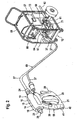
- a dry ice dispenser which can be connected to a dry ice blasting device 12 is shown schematically.
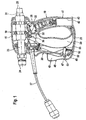
- the device 10 comprises a housing 14, which is formed by two housing half-shells 15, 16 and a central part 18 and of this pistol grip-like protruding first and second handle parts 19, 20 has.
- the two handle parts 19, 20 are connected together at their free end via a web 21.
- the middle part 18 surrounds a dispensing line 23, which passes through the middle part 18 and has an inlet 24 and an outlet 25.
- a feed line 27 can be connected to the inlet 24, via which optionally compressed air or a mixture of compressed air and dry ice can be guided by the dry ice blasting device 12 to the discharge line 23.
- a pivot lever 29 is arranged, which is mounted by means of a pivot pin 30 about a perpendicular to the longitudinal axis 31 of the dispensing line 23 aligned pivot axis 32 pivotally mounted on the central part 18 and the pivot pin 30 adjacent an approximately parallel to the longitudinal axis 31 aligned switching pin 33rd wearing.
- a first switching element in the form of a push button switch 35 can be actuated by pivoting the pivot lever 29.
- the push-button switch 35 is arranged in the first handle part 19 and can be connected via an electrical control line 37 with the dry ice blasting device 12 become.
- the pivot lever 29 with integrally formed switching pin 33 thus forms an actuating element for the push-button switch 35.
- a second switching element in the form of a selector switch 39 is arranged, which is also connected via the control line 37 with the dry ice blasting device 12.
- the free end region of the first handle part 19 surrounds a mounting element in the form of a holding tube 41, which forms a receptacle 42.
- the receptacle 42 is accessible via the free end 43 of the first handle part 19.
- a blocking element in the form of an L-shaped tilting lever 48 is pivotably mounted about a pivot axis 47 aligned parallel to the pivot axis 32 of the pivot lever 29.
- the rocker arm 48 has a first leg 49 and a second leg 50.
- the first limb 49 is arranged on the rear side of the second grip part 20 facing away from the first grip part 19, and the second limb 50 dips into the second grip part 20 and is acted upon by a return spring 52 by a spring force, by which the rocker arm 48 in the transition region between the first and the second leg 49 and 50 is pressed against a stop 53 formed on the inside by the second handle part 20.
- the rocker arm 48 By pivoting the rocker arm 48 against the restoring force exerted by the restoring spring 52, the first leg 49 can be pivoted into the second grip part 20. This can be done by a user of the dry ice dispensing device 10, the second handle portion 20 engages around with one hand.
- rocker arm 48 If the rocker arm 48 abuts on the stop 53, then it assumes a blocking position in which the free end of the first leg 49 rests against a projection 55 of the pivoting lever 29 facing the first leg 49. In its blocking position thus the rocker arm 48 blocks a movement of the pivot lever 29, so that in the locked position of the rocker arm 48 of the push-button switch 35 can not be operated by means of the pivot lever 29.
- To actuate the pushbutton switch 35 it is rather necessary first to pivot the rocker arm 48 against the spring force of the return spring 52 in a release position in which the free end of the first leg 49 is arranged at a distance from the projection 55, so that the pivot lever 29 to the Swivel axis 32 can be pivoted.
- the dry ice blasting apparatus 12 includes a dry ice storage bin 57 supported on a rack 58. Below the reservoir 57, a metering device 59 is arranged, as for example from the patent DE 10 2004 045 770 B3 is known. In the metering device 59 opens a compressed air inlet line 61, which can be connected via a supply line 62 to a compressed air source, not shown in the drawing, known per se.
- a compressed air outlet line 64 From the metering device 59 is a compressed air outlet line 64, to which the supply line 27 can be connected.
- the dry ice blasting device 12 also has a control unit 66, which via an electrical connecting line, not shown in the drawing connected to a connector socket 67. To the connector 67, the control line 37 can be connected.
- the dry ice blasting device 12 is connected to the dry ice dispenser 10 via a hose line 69 which comprises both the supply line 67 for the supply of compressed air and dry ice and the electrical control line 37 for the transmission of electrical control signals.
- the electrical control line 37 can be integrated in a jacket of the feed line 27.
- the metering device 59 can in the flow path of the compressed air dry ice granules, which is stored in the reservoir 57, are introduced, so that it mixes with the supplied via the compressed air inlet line 61 of the metering device 59 compressed air.
- the mixture of compressed air and dry ice can then be supplied via the compressed air outlet line 64 and the supply line 27 of the discharge line 23, so that the mixture can be applied via a connected to the outlet 25 of the discharge line 23 jet nozzle on a surface to be cleaned.
- the selector switch 39 the metering device 59 can be selectively switched on and off by the user. If the metering device 59 is turned on, then dry ice is added to the supplied compressed air, the metering device 59 is turned off, there is no admixture of dry ice.
- an electromagnetically actuated shut-off valve 71 is connected, which can be selectively opened and closed by operating the push-button switch 35 by means of the pivot lever 29. This gives the user the option of pivoting the Swing lever 29, the supply of compressed air to dry ice dispenser 10 optional release or lock.
- the dry ice dispenser 10 is thus characterized by easy handling.
- the user If the user only wants to direct compressed air to a surface to be cleaned, then he transfers the selector switch 39 into a switching position switching off the metering device 59 and then pivots the pivoting lever 29 to actuate the pushbutton switch 35 so that the shut-off valve 71 is opened and compressed air is supplied to the dry ice dispenser 10 , If the compressed air is to be mixed with dry ice granules, the user transfers the selector switch 39 into its switching position which switches on the metering device 59 and then again pivots the pivoting lever 29. This then results in dry ice granules being added to the compressed air to be supplied.
- the dry ice dispenser 10 can be fixed to the dry ice blasting device 12 in a parking position.
- the latter has for this purpose on the frame 58 of the control unit 66 adjacent to a vertically oriented holding mandrel 73, on which the first handle part 19 can be placed with the holding tube 41, wherein the retaining mandrel 73 dips into the receptacle 42 via the free end 43 of the first handle part 19.
- the handling of the dry ice dispenser 10 is thereby additionally simplified.
Landscapes
- Engineering & Computer Science (AREA)
- Mechanical Engineering (AREA)
- Nozzles (AREA)
- Beverage Vending Machines With Cups, And Gas Or Electricity Vending Machines (AREA)
- Confectionery (AREA)
- Multiple-Way Valves (AREA)
- Gloves (AREA)
- Freezing, Cooling And Drying Of Foods (AREA)
Description
- Die Erfindung betrifft ein Gerät mit den Merkmalen des Oberbegriffes von Patentanspruch 1.
- Mittels eines derartigen Gerätes kann wahlweise Druckluft oder ein Gemisch aus Druckluft und Trockeneis auf eine Fläche gerichtet werden, um die Fläche beispielsweise zu reinigen. Hierzu kann das Gerät an eine Trockeneisstrahlvorrichtung angeschlossen werden, die ihrerseits mit einer Druckluftquelle verbindbar ist und einen Vorrat von Trockeneis aufweist sowie eine Dosiereinrichtung, mit der das Trockeneis der Druckluft beigemischt werden kann. Das Trockeneis wird in Form von Trockeneisgranulat, das üblicherweise die Größe von Reiskörnern aufweist in Form sogenannter Pellets, bevorratet und mittels der Dosiereinrichtung in den Strömungsweg der Druckluft eingebracht, so dass es sich mit der Druckluft vermischt. Dies ermöglicht es, eine Fläche zu reinigen, denn bei Beaufschlagung der Fläche mit Trockeneisgranulat werden an der Fläche anhaftende Verunreinigungen stark abgekühlt, so dass sie verspröden und von der Fläche abgelöst werden. Das auf die Fläche auftreffende Trockeneisgranulat sublimiert beim Auftreffen, das heißt es geht direkt von der festen in die gasförmige Phase über und unterstützt dabei das Ablösen von an der Fläche anhaftenden Verunreinigungen. Trockeneisstrahlvorrichtungen, mit deren Hilfe Trockeneisgranulat in den Strömungsweg der Druckluft eingebracht werden können, sind beispielsweise aus der
DE 10 2004 045 770 B3 bekannt. - Die eingangs genannten Geräte weisen ein erstes und ein zweites Schaltelement auf. Durch Betätigung des ersten Schaltelementes kann ein Ventil der Trockeneisstrahlvorrichtung geöffnet werden, so dass dem Gerät über die Zuleitung Druckluft zugeführt werden kann, die vom Gerät auf die zu reinigende Fläche gerichtet werden kann. Durch Betätigung des zweiten Schaltelementes kann mittels der Dosiereinrichtung der Trockeneisstrahlvorrichtung der Druckluft Trockeneisgranulat beigemischt werden, so dass auf die zu reinigende Fläche das Gemisch aus Druckluft und Trockeneis gerichtet werden kann.
- Ein Gerät zum wahlweisen Abgeben von Druckluft oder einem Gemisch aus Druckluft und Trockeneis ist beispielsweise aus der
EP 0 521 794 B1 bekannt. Das bekannte Gerät weist einen Doppelkontaktschalter auf mit zwei Kontakten, die nacheinander durch Verschwenken eines Hebels betätigt werden können. Wird lediglich ein erster Kontakt betätigt, so wird vom Gerät ein erstes Steuersignal an die Trockeneisstrahlvorrichtung übertragen. Dies hat zur Folge, dass von der Trockeneisstrahlvorrichtung über die Zuleitung dem Gerät Druckluft zugeführt wird. Wird der zweite Kontakt betätigt, so wird vom Gerät ein zweites Steuersignal an die Trockeneisstrahlvorrichtung übertragen, aufgrund dessen der Druckluft Trockeneisgranulat beigemischt wird. Die Betätigung der beiden Kontakte ist von der Schwenkstellung des Hebels abhängig. Dies macht die Handhabung des bekannten Gerätes schwierig, da der Benutzer bei einem unbeabsichtigten Verschwenken des Hebels die Beimischung des Trockeneisgranulates zur zuzuführenden Druckluft aktiviert, das heißt der Benutzer muss bei der Betätigung des Hebels sorgfältig darauf achten, wie weit er den Hebel verschwenkt. Möchte er lediglich Druckluft auf eine Fläche richten, so muss er den Hebel zwar so weit verschwenken, dass der erste Kontakt betätigt wird, er darf den Hebel aber nicht weiter verschwenken, da sonst der Druckluft Trockeneis beigemischt wird. - Aus der Offenlegungsschrift
DE 196 24 652 A1 ist eine Vorrichtung zur Reinigung von Oberflächen mit Trockeneisgranulat bekannt, bei der eine Strahlpistole zum Einsatz kommt mit einer ersten Zuleitung für das Trockeneisgranulat und einer zweiten Zuleitung für Druckluft. Die zugeführte Menge an Granulat und an Druckluft kann der Bediener mit Hilfe von zwei Schaltelementen regulieren. Die beiden Schaltelemente können unabhängig voneinander verstellt werden, so dass je nach Oberflächenbeschaffenheit Aufprallintensität und Fördermenge des Granulates variiert werden können. In eine Mischkammer des Gerätes ragt eine Venturl-Düse, die am Ende der Druckluftleitung angeordnet ist, und in die Mischkammer mündet die Trockeneiszufuhrleltung. In der Mischkammer kann ein Gemisch aus Druckluft und Trockeneis hergestellt werden, das dann auf eine zu reinigende Oberfläche gerichtet werden kann. Mit Hilfe des ersten Schaltelementes in Form einer Drossel oder eines Kugelventils kann am Gerät die zugeführte Druckluft geregelt werden, und mittels des zweiten Schaltelementes in Form einer Drossel kann die Fördermenge an Trockeneis geregelt werden. Es kann auch vorgesehen sein, den Strahldruck bzw. die Strahlmenge an der Strahlpistole über eine elektrische Potentiometerregelung zu regeln. - Eine Strahlpistole für die Beaufschlagung einer Fläche mit einem Gemisch aus einer Flüssigkeit und einem Granulat in Form einer Wirbelstrahlpistole ist aus der Offenlegungsschrift
DE 196 54 779 A1 bekannt. Mit Hilfe eines Nadelventils kann die Zufuhr an Flüssigkeit, beispielsweise Wasser, geöffnet und geschlossen werden. Granulat wird in Form eines Granulat-Luftgemisches zugeführt, d. h. es kommen insgesamt zwei Zuleitungen zum Einsatz. Ein Abzugshebel betätigt sowohl das Nadelventil als auch einen Annäherungs- oder Druckschalter. - Aufgabe der vorliegenden Erfindung ist es, ein Gerät der gattungsgemäßen Art derart weiterzubilden, dass es eine einfachere Handhabung aufweist.
- Diese Aufgabe wird durch ein Gerät mit den Merkmalen von Patentanspruch 1 gelöst. Die beiden Schaltelemente können vom Benutzer unabhängig voneinander betätigt werden. Dadurch wird die Handhabung des Gerätes vereinfacht, denn eine unbeabsichtigte Beimischung von Trockeneis zur zuzuführenden Druckluft ist praktisch ausgeschlossen. Zur Beimischung von Trockeneis muss der Benutzer vielmehr unabhängig vom ersten Schaltelement das zweite Schaltelement betätigen. Dies gibt dem Benutzer insbesondere die Möglichkeit, zunächst das als Wahlschalter ausgebildete zweite Schaltelement in die von ihm gewünschte Schaltstellung zu überführen und erst danach das erste Schaltelement zur Bereitstellung von Druckluft zu betätigen. In einer ersten Schaltstellung des Wahlschalters wird dem Gerät lediglich Druckluft zugeführt, wohingegen in einer zweiten Schaltstellung des Wahlschalters der Druckluft Trockeneis beigemischt wird. Soll eine Fläche lediglich mit Druckluft beaufschlagt werden, so überführt der Benutzer den Wahlschalter in die erste Schaltstellung. Er kann dann durch Betätigung des ersten Schaltelementes wahlweise die Zuführung von Druckluft freigeben oder unterbinden. Soll eine Fläche mit einem Gemisch aus Druckluft und Trockeneis beaufschlagt werden, so überführt der Benutzer den Wahlschalter in seine zweite Schaltstellung, so dass bei anschließender Betätigung des ersten Schaltelementes der Druckluft wie gewünscht Trockeneis beigemischt wird.
- Die Steuerung der Trockeneisstrahlvorrichtung mittels des ersten und des zweiten Schaltelementes erfolgt elektrisch. Hierzu sind das erste Schaltelement und das zweite Schaltelement als elektrische Schalter ausgestaltet.
- Eine besonders einfache Handhabung kann dadurch erzielt werden, dass das zweite Schaltelement als Schiebe- oder Kippschalter ausgestaltet ist.
- Das erste Schaltelement ist als Druckknopfschalter ausgebildet.
- Bevorzugt weist das erfindungsgemäße Gerät ein Gehäuse auf mit einem die Abgabeleitung umgebenden Mittelteil und mindestens einem Griffteil, wobei das erste Schaltelement und das zweite Schaltelement am oder im Griffteil angeordnet sind. Dies ermöglicht eine kompakte Ausgestaltung des Gerätes.
- Das zweite Schaltelement ist bei einer vorteilhaften Ausführungsform an einer Außenseite des Griffteils positioniert. Die Schaltstellung des ersten Schaltelementes kann dadurch vom Benutzer auf einfache Weise erfasst werden.
- Das erste Schaltelement ist vorzugsweise innerhalb des Griffteiles positioniert und zur Betätigung des ersten Schaltelementes ist diesem ein bewegbares Betätigungselement zugeordnet. Das Betätigungselement ist am Gehäuse des erfindungsgemäßen Gerätes gelagert.
- Bevorzugt weist das Betätigungselement einen Schwenkhebel auf. Hierbei hat es sich als günstig erwiesen, wenn die Schwenkachse des Schwenkhebels senkrecht zur Längsachse der Abgabeleitung ausgerichtet ist. Bei einer bevorzugten Ausführungsform taucht der Schwenkhebel in das Gehäuse des Gerätes ein. So kann beispielsweise vorgesehen sein, dass vom Mittelteil des Gehäuses zusätzlich zu einem ersten Griffteil ein zweites Griffteil nach Art eines Pistolengriffes absteht, wobei der Schwenkhebel zwischen den beiden Griffteilen angeordnet ist und bei einer Schwenkbewegung in das zweite Griffteil eintaucht. Das zweite Griffteil kann zusammen mit dem Schwenkhebel vom Benutzer auf einfache Weise wie ein Pistolengriff umgriffen werden, und durch Verschwenken des Schwenkhebels kann das erste Schaltelement betätigt werden zum Ein- und Ausschalten der Druckluftzufuhr.
- Um eine unbeabsichtigte Betätigung des ersten Schaltelementes zu verhindern, ist bei einer vorteilhaften Ausführungsform das Betätigungselement mittels eines Sperrelementes arretierbar. Das erste Schaltelement kann somit mittels des Betätigungselementes nur dann betätigt werden, wenn zuvor das Sperrelement aus einer Sperrstellung in eine Freigabestellung überführt wird.
- Günstig ist es, wenn das Sperrelement federelastisch in seine Sperrstellung vorgespannt ist. Das unbelastete Sperrelement nimmt somit selbsttätig seine Sperrstellung ein, in der es eine Betätigung des ersten Schaltelementes und damit eine Zufuhr von Druckluft blockiert.
- Das Sperrelement kann beispielsweise als Kipphebel ausgestaltet sein. Hierbei ist es günstig, wenn das Sperrelement am zweiten Griffteil verschwenkbar gelagert ist. Die Schwenkachse des Sperrelementes kann parallel zur Schwenkachse des Schwenkhebels ausgerichtet sein.
- Bei einer besonders bevorzugten Ausführungsform sind das Betätigungselement und das Sperrelement vom Benutzer mit einer Hand umgreifbar. Die Handhabung des erfindungsgemäßen Gerätes wird dadurch zusätzlich vereinfacht. Zum Einschalten der Druckluftzufuhr kann der Benutzer gleichzeitig das Betätigungselement und das Sperrelement umgreifen, wobei das Sperrelement in seine Freigabestellung überführt wird und dadurch das Betätigungselement bewegt werden kann.
- An den Auslass der Abgabeleitung kann eine Strahldüse angeschlossen werden. Dadurch kann eine Fläche je nach Ausgestaltung der Strahldüse mit einem Druckluftstrahl, dem wahlweise Trockeneis beigemischt ist, von unterschiedlicher Geometrie beaufschlagt werden. Beispielsweise kann eine Flachstrahldüse zum Einsatz kommen, mit deren Hilfe ein flacher, jedoch breit gefächerter Druckluftstrahl erzeugt werden kann, oder es kann auch eine Punktstrahldüse zum Einsatz kommen, mit deren Hilfe ein sehr komprimierter Druckluftstrahl mit wahlweiser Beimischung von Trockeneis erzeugt werden kann. Die Strahldüse kann mit dem Auslass beispielsweise verschraubt werden. Alternativ kann eine Bajonettkupplung zum Einsatz kommen. Um das Verbinden der Strahldüse mit dem Auslass der Abgabeleitung zu vereinfachen, ist bei einer besonders bevorzugten Ausführungsform der Erfindung vorgesehen, dass das Gerät ein Montageelement aufweist zur lösbaren Montage des Gerätes an der Trockeneisstrahlvorrichtung. Dies ermöglicht es, das Gerät in einer Parkposition an der Trockeneisstrahlvorrichtung zu haltern, um an den Auslass der Abgabeleitung eine Strahldüse anzuschließen. Die Handhabung des Gerätes wird dadurch weiter vereinfacht.
- Bevorzugt ist das Montageelement mit einem korrespondierenden Montageelement der Trockeneisstrahlvorrichtung steckbar verbindbar. Das Herstellen einer Steckverbindung ist für den Benutzer auf einfache Weise zu bewerkstelligen, insbesondere kann der Benutzer das Montageelement mit einer Hand mit dem korrespondierenden Montageelement der Trockeneisstrahlvorrichtung verbinden.
- Es kann beispielsweise vorgesehen sein, dass das Montageelement eine Aufnahme ausbildet, die auf ein Halteelement der Trockeneisstrahlvorrichtung aufsetzbar ist. Das Halteelement bildet ein korrespondierendes Montageelement, mit dem das eine Aufnahme aufweisende Montageelement des erfindungsgemäßen Gerätes steckbar verbindbar ist.
- Alternativ kann vorgesehen sein, dass das Montageelement des Gerätes als Haltestift ausgebildet ist, der in eine Aufnahme der Trockeneisstrahlvorrichtung einsetzbar ist.
- Das Montageelement des Gerätes ist vorzugsweise als Halterohr ausgestaltet, dass auf einen Haltedorn der Trockeneisstrahlvorrichtung aufsetzbar ist. Das Halterohr zeichnet sich durch eine hohe mechanische Belastbarkeit aus. Es kann beispielsweise aus Metall gefertigt sein.
- Wie bereits erläutert, kann das Gerät ein Gehäuse aufweisen mit einem die Abgabeleitung umgebenden Mittelteil, von dem mindestens ein Griffteil absteht. Günstig ist es, wenn das Montageelement am oder im Griffteil angeordnet ist. Eine Integration des Montageelementes in das Griffteil ermöglicht es, das erfindungsgemäße Gerät besonders kompakt auszugestalten, wobei dennoch die Möglichkeit gegeben ist, das Gerät in einer Parkposition an der Trockeneisstrahlvorrichtung zu haltern.
- Das Gehäuse des Gerätes ist bei einer kostengünstig herstellbaren Ausführungsform aus Kunststoff gefertigt, wohingegen das Montageelement bevorzugt aus Metall gefertigt ist zur Erzielung einer besonders hohen mechanischen Belastbarkeit.
- Es kann beispielsweise vorgesehen sein, dass das Gehäuse zwei Gehäusehalbschalen aufweist, die die beiden Schaltelemente sowie das Montageelement und die Abgabeleitung aufnehmen, wobei die Abgabeleitung ein Mittelteil des Gehäuses durchgreift.
- Die nachfolgende Beschreibung einer bevorzugten Ausführungsform der Erfindung dient im Zusammenhang mit der Zeichnung der näheren Erläuterung. Es zeigen:
- Figur 1:
- eine Schnittansicht eines erfindungsgemäßen Trockeneisabgabege- rätes und
- Figur 2:
- eine perspektivische Darstellung des erfindungsgemäßen Trocken- eisabgabegerätes, das an eine Trockeneisstrahlvorrichtung ange- schlossen ist.
- In der Zeichnung ist schematisch ein insgesamt mit dem Bezugszeichen 10 belegtes Trockeneisabgabegerät dargestellt, das an eine Trockeneisstrahlvorrichtung 12 angeschlossen werden kann. Das Gerät 10 umfasst ein Gehäuse 14, das von zwei Gehäusehalbschalen 15, 16 gebildet wird und ein Mittelteil 18 sowie von diesem pistolengriffartig abstehende erste und zweite Griffteile 19, 20 aufweist. Die beiden Griffteile 19, 20 sind an ihrem freien Ende über einen Steg 21 miteinander verbunden.
- Das Mittelteil 18 umgibt eine Abgabeleitung 23, die das Mittelteil 18 durchgreift und einen Einlass 24 sowie einen Auslass 25 aufweist. An den Einlass 24 kann eine Zuleitung 27 angeschlossen werden, über die wahlweise Druckluft oder ein Gemisch aus Druckluft und Trockeneis von der Trockeneisstrahlvorrichtung 12 zur Abgabeleitung 23 geführt werden kann. An den Auslass 25 kann eine an sich bekannte und deshalb in der Zeichnung nicht dargestellte Strahldüse angeschlossen werden.
- Zwischen den beiden Griffteilen 19, 20 ist ein Schwenkhebel 29 angeordnet, der mittels eines Schwenkzapfens 30 um eine senkrecht zur Längsachse 31 der Abgabeleitung 23 ausgerichtete Schwenkachse 32 verschwenkbar am Mittelteil 18 gelagert ist und dem Schwenkzapfen 30 benachbart einen ungefähr parallel zur Längsachse 31 ausgerichteten Schaltstift 33 trägt. Mittels des Schaltstiftes 33 kann ein erstes Schaltelement in Form eines Druckknopfschalters 35 durch Verschwenken des Schwenkhebels 29 betätigt werden. Der Druckknopfschalter 35 ist im ersten Griffteil 19 angeordnet und kann über eine elektrische Steuerleitung 37 mit der Trockeneisstrahlvorrichtung 12 verbunden werden. Der Schwenkhebel 29 mit angeformtem Schaltstift 33 bildet somit ein Betätigungselement für den Druckknopfschalter 35.
- Seitlich ist am ersten Griffteil 19 ein zweites Schaltelement in Form eines Wahlschalters 39 angeordnet, der über die Steuerleitung 37 ebenfalls mit der Trockeneisstrahlvorrichtung 12 verbindbar ist.
- Der freie Endbereich des ersten Griffteiles 19 umgibt ein Montageelement in Form eines Halterohres 41, das eine Aufnahme 42 ausbildet. Die Aufnahme 42 ist über das freie Ende 43 des ersten Griffteiles 19 zugänglich.
- Im Bereich des freien Endes 45 des zweiten Griffteiles 20 ist um eine parallel zur Schwenkachse 32 des Schwenkhebels 29 ausgerichtete Schwenkachse 47 ein Sperrelement in Form eines L-förmigen Kipphebels 48 schwenkbar gelagert. Der Kipphebel 48 weist einen ersten Schenkel 49 und einen zweiten Schenkel 50 auf. Der erste Schenkel 49 ist an der dem ersten Griffteil 19 abgewandten Rückseite des zweiten Griffteiles 20 angeordnet, und der zweite Schenkel 50 taucht in das zweite Griffteil 20 ein und wird von einer Rückstellfeder 52 mit einer Federkraft beaufschlagt, durch die der Kipphebel 48 im Übergangsbereich zwischen dem ersten und dem zweiten Schenkel 49 bzw. 50 gegen einen vom zweiten Griffteil 20 innenseitig ausgebildeten Anschlag 53 gedrückt wird. Durch Verschwenken des Kipphebels 48 entgegen der von der Rückstellfeder 52 ausgeübten Rückstellkraft kann der erste Schenkel 49 in das zweite Griffteil 20 eingeschwenkt werden. Dies kann dadurch erfolgen, dass ein Benutzer des Trockeneisabgabegerätes 10 den zweiten Griffteil 20 mit einer Hand umgreift.
- Liegt der Kipphebel 48 am Anschlag 53 an, so nimmt er eine Sperrstellung ein, in der das freie Ende des ersten Schenkels 49 an einem dem ersten Schenkel 49 zugewandten Vorsprung 55 des Schwenkhebels 29 anliegt. In seiner Sperrstellung blockiert somit der Kipphebel 48 eine Bewegung des Schwenkhebels 29, so dass in der Sperrstellung des Kipphebels 48 der Druckknopfschalter 35 mittels des Schwenkhebels 29 nicht betätigt werden kann. Zur Betätigung des Druckknopfschalters 35 ist es vielmehr erforderlich, zunächst den Kipphebel 48 entgegen der Federkraft der Rückstellfeder 52 in eine Freigabestellung zu verschwenken, in der das freie Ende des ersten Schenkels 49 im Abstand zum Vorsprung 55 angeordnet ist, so dass der Schwenkhebel 29 um die Schwenkachse 32 verschwenkt werden kann.
- Die Trockeneisstrahlvorrichtung 12 umfasst einen Vorratsbehälter 57 für Trockeneis, der an einem Gestell 58 gehalten ist. Unterhalb des Vorratsbehälters 57 ist eine Dosiereinrichtung 59 angeordnet, wie sie beispielsweise aus der Patentschrift
DE 10 2004 045 770 B3 bekannt ist. In die Dosiereinrichtung 59 mündet eine Druckluft-Einlassleitung 61 ein, die über eine Versorgungsleitung 62 an eine in der Zeichnung nicht dargestellte, an sich bekannte Druckluftquelle angeschlossen werden kann. - Von der Dosiereinrichtung 59 geht eine Druckluft-Auslassleitung 64 aus, an die die Zuleitung 27 angeschlossen werden kann.
- Die Trockeneisstrahlvorrichtung 12 weist außerdem eine Steuereinheit 66 auf, die über eine in der Zeichnung nicht dargestellte elektrische Verbindungsleitung mit einer Anschlussbuchse 67 verbunden ist. An die Anschlussbuchse 67 kann die Steuerleitung 37 angeschlossen werden.
- Die Verbindung der Trockeneisstrahlvorrichtung 12 mit dem Trockeneisabgabegerät 10 erfolgt über eine Schlauchleitung 69, die sowohl die Zuleitung 67 für die Zufuhr von Druckluft und Trockeneis als auch die elektrische Steuerleitung 37 zur Übertragung elektrischer Steuersignale umfasst. Die elektrische Steuerleitung 37 kann hierzu in einen Mantel der Zuleitung 27 integriert sein.
- Mittels der Dosiereinrichtung 59 kann in den Strömungsweg der Druckluft Trockeneisgranulat, das im Vorratsbehälter 57 bevorratet ist, eingebracht werden, so dass es sich mit der über die Druckluft-Einlassleitung 61 der Dosiereinrichtung 59 zugeführten Druckluft vermischt. Das Gemisch aus Druckluft und Trockeneis kann dann über die Druckluft-Auslassleitung 64 und die Zuleitung 27 der Abgabeleitung 23 zugeführt werden, so dass das Gemisch über eine an den Auslass 25 der Abgabeleitung 23 angeschlossene Strahldüse auf eine zu reinigende Fläche aufgebracht werden kann. Mit Hilfe des Wahlschalters 39 kann die Dosiereinrichtung 59 vom Benutzer wahlweise ein- und ausgeschaltet werden. Ist die Dosiereinrichtung 59 eingeschaltet, so wird Trockeneis der zuzuführenden Druckluft beigemischt, ist die Dosiereinrichtung 59 ausgeschaltet, so erfolgt keine Beimischung von Trockeneis.
- In die Druckluft-Einlassleitung 61 ist ein elektromagnetisch betätigbares Sperrventil 71 geschaltet, das durch Betätigung des Druckknopfschalters 35 mittels des Schwenkhebels 29 wahlweise geöffnet und geschlossen werden kann. Dies gibt dem Benutzer die Möglichkeit, durch Verschwenken des Schwenkhebels 29 die Zufuhr von Druckluft zum Trockeneisabgabegerät 10 wahlweise freizugeben oder zu sperren. Das Trockeneisabgabegerät 10 zeichnet sich somit durch eine einfache Handhabung aus. Möchte der Benutzer lediglich Druckluft auf eine zu reinigende Fläche richten, so überführt er den Wahlschalter 39 in eine die Dosiereinrichtung 59 ausschaltende Schaltstellung und verschwenkt anschließend den Schwenkhebel 29 zur Betätigung des Druckknopfschalters 35, so dass das Sperrventil 71 geöffnet und dem Trockeneisabgabegerät 10 Druckluft zugeführt wird. Soll der Druckluft Trockeneisgranulat beigemischt werden, so überführt der Benutzer den Wahlschalter 39 in seine die Dosiereinrichtung 59 einschaltende Schaltstellung und verschwenkt anschließend erneut den Schwenkhebel 29.Dies hat dann zur Folge, dass der zuzuführenden Druckluft Trockeneisgranulat beigemischt wird.
- Ist das Trockeneisabgabegerät 10 nicht in Benutzung oder soll beispielsweise eine Strahldüse an den Auslass 25 angeschlossen werden, so kann hierzu das Trockeneisabgabegerät 10 in einer Parkposition an der Trockeneisstrahlvorrichtung 12 festgelegt werden. Letztere weist hierzu am Gestell 58 der Steuereinheit 66 benachbart einen vertikal ausgerichteten Haltedorn 73 auf, auf den das erste Griffteil 19 mit dem Halterohr 41 aufgesetzt werden kann, wobei der Haltedorn 73 über das freie Ende 43 des ersten Griffteiles 19 in die Aufnahme 42 eintaucht. Die Handhabung des Trockeneisabgabegerätes 10 wird dadurch zusätzlich vereinfacht.
Claims (14)
- Trockeneisabgabegerät zum wahlweisen Abgeben von Druckluft oder einem Gemisch aus Druckluft und Trockeneis für eine Trockeneisstrahlvorrichtung (12), mit einer Abgabeleitung (23), an die eine Zuleitung (27) für Druckluft und Trockeneis anschließbar ist, und mit einem ersten und einem zweiten Schaltelement (35, 39), die über eine Steuerleitung (37) mit der Trockeneisstrahlvorrichtung (12) verbindbar sind, wobei mittels des ersten Schaltelementes (35) die Zufuhr von Druckluft und mittels des zweiten Schaltelementes (39) die Beimischung von Trockeneis ein- und ausschaltbar ist, und wobei das zweite Schaltelement (39) unabhangig vom ersten Schaltelement (35) betätigbar ist, wobei die beiden Schaltelemente (35, 39) über eine elektrische Steuerleitung (37) mit der Trockeneisstrahlvorrichtung (12) verbindbar sind und mittels des zweiten Schaltelementes (39) die Beimischung von Trockeneis in der Trockeneisstrahlvorrichtung (12) zur zuzuführenden Druckluft ein- und ausschaltbar ist, und die Abgabeleitung (23) einen Einlass (24) und einen Auslass (25) aufweist, dadurch gekennzeichnet, dass das erste Schaltelement (35) als elektrischer Druckknopfschalter ausgestaltet ist und dass das zweite Schaltelement (39) als elektrischer Wahlschalter ausgestaltet ist, der vom Benutzer zwischen einer ersten Schaltstellung und einer zweiten Schaltstellung hin und her bewegbar ist, wobei an den Einlass (24) eine einzige Zuleitung (27) anschließbar ist, über die wahlweise Druckluft oder ein Gemisch aus Druckluft und Trockeneis von der Trockeneisstrahlvorrichtung (12) zur Abgabeleitung (23) zuführbar ist, und wobei an den Auslass (25) eine Strahldüse anschließbar ist.
- Gerät nach Anspruch 1, dadurch gekennzeichnet, dass das Gerät (10) ein Gehäuse (14) aufweist mit einem die Abgabeleitung (23) umgebenden Mittelteil (18) und mindestens einem Griffteil (19), wobei das erste Schaltelement (35) und das zweite Schaltelement (39) am oder im Griffteil (19) angeordnet sind.
- Gerät nach Anspruch 2, dadurch gekennzeichnet, dass das erste Schaltelement (35) innerhalb des Griffteiles (19) positioniert ist und dass dem ersten Schaltelement (35) ein bewegbares Betätigungselement (29) zugeordnet ist.
- Gerät nach Anspruch 3, dadurch gekennzeichnet, dass das Betätigungselement einen Schwenkhebel (29) aufweist.
- Gerät nach Anspruch 3 oder 4, dadurch gekennzeichnet, dass das Betätigungselement (29) mittels eines Sperrelementes (48) arretierbar ist.
- Gerät nach Anspruch 5, dadurch gekennzeichnet, dass das Sperrelement (48) federelastisch in eine Sperrstellung vorgespannt ist.
- Gerät nach Anspruch 5 oder 6, dadurch gekennzeichnet, dass das Sperrelement als Kipphebel (48) ausgestaltet ist.
- Gerät nach Anspruch 5, 6 oder 7, dadurch gekennzeichnet, dass das Betätigungselement (29) und das Sperrelement (48) vom Benutzer mit einer Hand umgreifbar sind.
- Gerät nach einem der voranstehenden Ansprüche, dadurch gekennzeichnet, dass das Gerät (10) ein Montageelement (41) aufweist zur lösbaren Montage des Gerätes (10) an der Trockeneisstrahlvorrichtung (12).
- Gerät nach Anspruch 9, dadurch gekennzeichnet, dass das Montageelement (41) mit einem korrespondierenden Montageelement (73) der Trockeneisstrahlvorrichtung (12) steckbar verbindbar ist.
- Gerät nach Anspruch 9 oder 10, dadurch gekennzeichnet, dass das Montageelement (41) eine Aufnahme (42) aufweist, die auf ein Halteelement (73) der Trockeneisstrahlvorrichtung (12) aufsetzbar ist.
- Gerät nach Anspruch 9, 10 oder 11, dadurch gekennzeichnet, dass das Montageelement als Halterohr (41) ausgestaltet ist, das auf einen Haltedorn (73) der Trockeneisstrahlvorrichtung (12) aufsetzbar ist.
- Gerät nach einem der Ansprüche 9 bis 12, dadurch gekennzeichnet, dass das Gerät (10) ein Gehäuse (14) aufweist mit einem die Abgabeleitung (23) umgebenden Mittelteil (18), von dem mindestens ein Griffteil (19; 20) absteht, wobei das Montageelement (41) am oder im Griffteil (19) angeordnet ist.
- Gerät nach Anspruch 13, dadurch gekennzeichnet, dass das Gehäuse (14) aus Kunststoff und das Montageelement (41) aus Metall gefertigt ist.
Applications Claiming Priority (2)
| Application Number | Priority Date | Filing Date | Title |
|---|---|---|---|
| DE102005057115A DE102005057115A1 (de) | 2005-11-28 | 2005-11-28 | Trockeneisabgabegerät |
| PCT/EP2006/009362 WO2007059819A1 (de) | 2005-11-28 | 2006-09-27 | Trockeneisabgabegerät |
Publications (2)
| Publication Number | Publication Date |
|---|---|
| EP1954444A1 EP1954444A1 (de) | 2008-08-13 |
| EP1954444B1 true EP1954444B1 (de) | 2011-01-26 |
Family
ID=37453088
Family Applications (1)
| Application Number | Title | Priority Date | Filing Date |
|---|---|---|---|
| EP06805886A Not-in-force EP1954444B1 (de) | 2005-11-28 | 2006-09-27 | Trockeneisabgabegerät |
Country Status (5)
| Country | Link |
|---|---|
| EP (1) | EP1954444B1 (de) |
| AT (1) | ATE496731T1 (de) |
| DE (2) | DE102005057115A1 (de) |
| DK (1) | DK1954444T3 (de) |
| WO (1) | WO2007059819A1 (de) |
Families Citing this family (5)
| Publication number | Priority date | Publication date | Assignee | Title |
|---|---|---|---|---|
| DE102006015805A1 (de) * | 2006-04-03 | 2007-10-04 | Alfred Kärcher Gmbh & Co. Kg | Strahlmittelaustragsdüse |
| SK288682B6 (sk) | 2015-08-29 | 2019-07-02 | Ics Ice Cleaning Systems S. R. O. | Zásobník suchého ľadu pre zariadenia na čistenie suchým ľadom |
| EP3254807B1 (de) | 2016-06-07 | 2023-12-27 | desisa GmbH | Vorrichtung und verfahren zum reinigen mit einer strahlvorrichtung |
| DE102019202220A1 (de) * | 2019-02-19 | 2020-08-20 | Robel Bahnbaumaschinen Gmbh | Vorrichtung und Verfahren zum manuellen Behandeln einer Oberfläche mit Trockeneis |
| WO2024123856A1 (en) * | 2022-12-07 | 2024-06-13 | Nu-Ice Age, Inc. | Heated handle and hose for dry ice blasting system |
Citations (2)
| Publication number | Priority date | Publication date | Assignee | Title |
|---|---|---|---|---|
| GB586291A (en) * | 1944-08-18 | 1947-03-13 | Cardox Corp | Fire extinguishing system |
| WO1991009800A1 (en) * | 1989-12-27 | 1991-07-11 | Alpheus Cleaning Technologies Corp. | Particulate delivery system |
Family Cites Families (7)
| Publication number | Priority date | Publication date | Assignee | Title |
|---|---|---|---|---|
| DE1931603U (de) * | 1965-10-23 | 1966-01-27 | Cloos Fa Carl | Vorrichtung fuer eine elektrische schweissanlage mit einer ueber eine hohlleitung mit elektrodendraht zu beschickender schweisspistole. |
| FR2678527B1 (fr) * | 1991-07-05 | 1993-09-10 | Commissariat Energie Atomique | Appareil de stockage et de projection de billes de glace. |
| DE19624652A1 (de) * | 1995-10-30 | 1997-10-16 | Birgit Papcke | Verfahren zur Oberflächenbehandlung, insbesondere Reinigung von Oberflächen mit CO¶2¶-Trockeneisgranulat und eine Vorrichtung zur Durchführung dieses Verfahrens |
| DE19654779A1 (de) * | 1996-12-31 | 1998-07-02 | Josef Bauer | Strahlpistole für die Naßstrahlung |
| DE29709057U1 (de) * | 1997-05-23 | 1997-07-24 | Thieme, Martin, 48346 Ostbevern | Fahrbare Sandstrahlanlage |
| WO2006000274A1 (de) * | 2004-06-24 | 2006-01-05 | Jens Werner Kipp | Vorrichtung und verfahren zur zuführung von flüssigem kohlendioxid |
| DE102004045770B3 (de) * | 2004-09-15 | 2005-09-08 | Alfred Kärcher Gmbh & Co. Kg | Trockeneisstrahlvorrichtung |
-
2005
- 2005-11-28 DE DE102005057115A patent/DE102005057115A1/de not_active Withdrawn
-
2006
- 2006-09-27 DE DE502006008828T patent/DE502006008828D1/de active Active
- 2006-09-27 WO PCT/EP2006/009362 patent/WO2007059819A1/de not_active Ceased
- 2006-09-27 AT AT06805886T patent/ATE496731T1/de active
- 2006-09-27 EP EP06805886A patent/EP1954444B1/de not_active Not-in-force
- 2006-09-27 DK DK06805886.6T patent/DK1954444T3/da active
Patent Citations (2)
| Publication number | Priority date | Publication date | Assignee | Title |
|---|---|---|---|---|
| GB586291A (en) * | 1944-08-18 | 1947-03-13 | Cardox Corp | Fire extinguishing system |
| WO1991009800A1 (en) * | 1989-12-27 | 1991-07-11 | Alpheus Cleaning Technologies Corp. | Particulate delivery system |
Also Published As
| Publication number | Publication date |
|---|---|
| EP1954444A1 (de) | 2008-08-13 |
| DE502006008828D1 (de) | 2011-03-10 |
| DE102005057115A1 (de) | 2007-05-31 |
| ATE496731T1 (de) | 2011-02-15 |
| DK1954444T3 (da) | 2011-05-09 |
| WO2007059819A1 (de) | 2007-05-31 |
Similar Documents
| Publication | Publication Date | Title |
|---|---|---|
| DE2624728C3 (de) | Vorrichtung zum Abgeben von Schaum | |
| EP0692224B1 (de) | Medizinisches Multifunktionsinstrument zum endoskopischen Operieren | |
| CH670580A5 (de) | ||
| EP1852190B1 (de) | Schaumeinrichtung | |
| EP0738668A1 (de) | Aerosolbetätiger mit Handgriff | |
| EP4065242B1 (de) | Lanze, insbesondere löschlanze für die brandbekämpfung | |
| WO2018184659A1 (de) | Handgeführtes druckreinigungsgerät | |
| WO2020114577A1 (de) | Farbsprühpistole | |
| EP1954444A1 (de) | Trockeneisabgabegerät | |
| EP1232796A1 (de) | Selbstreinigende Spritzpistolendüse | |
| DE102009039844A1 (de) | Auspressgerät | |
| EP1262240B1 (de) | Wasserausflussarmatur mit einer Umschaltvorrichtung | |
| EP1053077B1 (de) | Strahlmittel-injektorpistole | |
| DE69704431T2 (de) | Reinigungslanze | |
| WO1998019782A1 (de) | Spritzpistole mit zugeordneter mischkammer | |
| EP2380667A1 (de) | Sprühpistole | |
| DE69716693T2 (de) | Steuerungsvorrichtung für eine Reinigungsvorrichtung für verseuchte Oberflächen | |
| EP0804970A2 (de) | Handspritzpistole für ein Hochdruckreinigungsgerät | |
| DE19521536A1 (de) | Spritzeinrichtung zur kombinierten Hochdruck/Niederdruck-Reinigung | |
| DE4428634C2 (de) | Spritzpistole mit einem Griffstück und einem betätigbaren Ventilstößel | |
| DE29607056U1 (de) | Vorrichtung zur Versorgung einer Strahlpistole mit Arbeitsmedien | |
| AT358417B (de) | Hochdruck-waschlanze | |
| DE4443795C2 (de) | Handstück eines Dampfreinigungsgeräts | |
| DE2827402A1 (de) | Giessbrause | |
| DE20014061U1 (de) | Flammenpulverspritzpistole |
Legal Events
| Date | Code | Title | Description |
|---|---|---|---|
| PUAI | Public reference made under article 153(3) epc to a published international application that has entered the european phase |
Free format text: ORIGINAL CODE: 0009012 |
|
| 17P | Request for examination filed |
Effective date: 20080315 |
|
| AK | Designated contracting states |
Kind code of ref document: A1 Designated state(s): AT BE BG CH CY CZ DE DK EE ES FI FR GB GR HU IE IS IT LI LT LU LV MC NL PL PT RO SE SI SK TR |
|
| 17Q | First examination report despatched |
Effective date: 20090206 |
|
| GRAP | Despatch of communication of intention to grant a patent |
Free format text: ORIGINAL CODE: EPIDOSNIGR1 |
|
| GRAS | Grant fee paid |
Free format text: ORIGINAL CODE: EPIDOSNIGR3 |
|
| GRAA | (expected) grant |
Free format text: ORIGINAL CODE: 0009210 |
|
| AK | Designated contracting states |
Kind code of ref document: B1 Designated state(s): AT BE BG CH CY CZ DE DK EE ES FI FR GB GR HU IE IS IT LI LT LU LV MC NL PL PT RO SE SI SK TR |
|
| REG | Reference to a national code |
Ref country code: GB Ref legal event code: FG4D Free format text: NOT ENGLISH |
|
| REG | Reference to a national code |
Ref country code: CH Ref legal event code: NV Representative=s name: ISLER & PEDRAZZINI AG Ref country code: CH Ref legal event code: EP |
|
| REG | Reference to a national code |
Ref country code: IE Ref legal event code: FG4D Free format text: LANGUAGE OF EP DOCUMENT: GERMAN |
|
| REF | Corresponds to: |
Ref document number: 502006008828 Country of ref document: DE Date of ref document: 20110310 Kind code of ref document: P |
|
| REG | Reference to a national code |
Ref country code: DE Ref legal event code: R096 Ref document number: 502006008828 Country of ref document: DE Effective date: 20110310 |
|
| REG | Reference to a national code |
Ref country code: DK Ref legal event code: T3 |
|
| REG | Reference to a national code |
Ref country code: NL Ref legal event code: VDEP Effective date: 20110126 |
|
| LTIE | Lt: invalidation of european patent or patent extension |
Effective date: 20110126 |
|
| PG25 | Lapsed in a contracting state [announced via postgrant information from national office to epo] |
Ref country code: IS Free format text: LAPSE BECAUSE OF FAILURE TO SUBMIT A TRANSLATION OF THE DESCRIPTION OR TO PAY THE FEE WITHIN THE PRESCRIBED TIME-LIMIT Effective date: 20110526 Ref country code: SE Free format text: LAPSE BECAUSE OF FAILURE TO SUBMIT A TRANSLATION OF THE DESCRIPTION OR TO PAY THE FEE WITHIN THE PRESCRIBED TIME-LIMIT Effective date: 20110126 Ref country code: GR Free format text: LAPSE BECAUSE OF FAILURE TO SUBMIT A TRANSLATION OF THE DESCRIPTION OR TO PAY THE FEE WITHIN THE PRESCRIBED TIME-LIMIT Effective date: 20110427 Ref country code: ES Free format text: LAPSE BECAUSE OF FAILURE TO SUBMIT A TRANSLATION OF THE DESCRIPTION OR TO PAY THE FEE WITHIN THE PRESCRIBED TIME-LIMIT Effective date: 20110507 Ref country code: PT Free format text: LAPSE BECAUSE OF FAILURE TO SUBMIT A TRANSLATION OF THE DESCRIPTION OR TO PAY THE FEE WITHIN THE PRESCRIBED TIME-LIMIT Effective date: 20110526 Ref country code: LT Free format text: LAPSE BECAUSE OF FAILURE TO SUBMIT A TRANSLATION OF THE DESCRIPTION OR TO PAY THE FEE WITHIN THE PRESCRIBED TIME-LIMIT Effective date: 20110126 Ref country code: LV Free format text: LAPSE BECAUSE OF FAILURE TO SUBMIT A TRANSLATION OF THE DESCRIPTION OR TO PAY THE FEE WITHIN THE PRESCRIBED TIME-LIMIT Effective date: 20110126 |
|
| REG | Reference to a national code |
Ref country code: IE Ref legal event code: FD4D |
|
| PG25 | Lapsed in a contracting state [announced via postgrant information from national office to epo] |
Ref country code: FI Free format text: LAPSE BECAUSE OF FAILURE TO SUBMIT A TRANSLATION OF THE DESCRIPTION OR TO PAY THE FEE WITHIN THE PRESCRIBED TIME-LIMIT Effective date: 20110126 Ref country code: SI Free format text: LAPSE BECAUSE OF FAILURE TO SUBMIT A TRANSLATION OF THE DESCRIPTION OR TO PAY THE FEE WITHIN THE PRESCRIBED TIME-LIMIT Effective date: 20110126 Ref country code: PL Free format text: LAPSE BECAUSE OF FAILURE TO SUBMIT A TRANSLATION OF THE DESCRIPTION OR TO PAY THE FEE WITHIN THE PRESCRIBED TIME-LIMIT Effective date: 20110126 Ref country code: CY Free format text: LAPSE BECAUSE OF FAILURE TO SUBMIT A TRANSLATION OF THE DESCRIPTION OR TO PAY THE FEE WITHIN THE PRESCRIBED TIME-LIMIT Effective date: 20110126 Ref country code: NL Free format text: LAPSE BECAUSE OF FAILURE TO SUBMIT A TRANSLATION OF THE DESCRIPTION OR TO PAY THE FEE WITHIN THE PRESCRIBED TIME-LIMIT Effective date: 20110126 Ref country code: BG Free format text: LAPSE BECAUSE OF FAILURE TO SUBMIT A TRANSLATION OF THE DESCRIPTION OR TO PAY THE FEE WITHIN THE PRESCRIBED TIME-LIMIT Effective date: 20110426 |
|
| PG25 | Lapsed in a contracting state [announced via postgrant information from national office to epo] |
Ref country code: IE Free format text: LAPSE BECAUSE OF FAILURE TO SUBMIT A TRANSLATION OF THE DESCRIPTION OR TO PAY THE FEE WITHIN THE PRESCRIBED TIME-LIMIT Effective date: 20110126 Ref country code: EE Free format text: LAPSE BECAUSE OF FAILURE TO SUBMIT A TRANSLATION OF THE DESCRIPTION OR TO PAY THE FEE WITHIN THE PRESCRIBED TIME-LIMIT Effective date: 20110126 |
|
| PG25 | Lapsed in a contracting state [announced via postgrant information from national office to epo] |
Ref country code: SK Free format text: LAPSE BECAUSE OF FAILURE TO SUBMIT A TRANSLATION OF THE DESCRIPTION OR TO PAY THE FEE WITHIN THE PRESCRIBED TIME-LIMIT Effective date: 20110126 Ref country code: RO Free format text: LAPSE BECAUSE OF FAILURE TO SUBMIT A TRANSLATION OF THE DESCRIPTION OR TO PAY THE FEE WITHIN THE PRESCRIBED TIME-LIMIT Effective date: 20110126 Ref country code: CZ Free format text: LAPSE BECAUSE OF FAILURE TO SUBMIT A TRANSLATION OF THE DESCRIPTION OR TO PAY THE FEE WITHIN THE PRESCRIBED TIME-LIMIT Effective date: 20110126 |
|
| PLBE | No opposition filed within time limit |
Free format text: ORIGINAL CODE: 0009261 |
|
| STAA | Information on the status of an ep patent application or granted ep patent |
Free format text: STATUS: NO OPPOSITION FILED WITHIN TIME LIMIT |
|
| 26N | No opposition filed |
Effective date: 20111027 |
|
| REG | Reference to a national code |
Ref country code: DE Ref legal event code: R097 Ref document number: 502006008828 Country of ref document: DE Effective date: 20111027 |
|
| BERE | Be: lapsed |
Owner name: ALFRED KARCHER G.M.B.H. & CO. KG Effective date: 20110930 |
|
| PG25 | Lapsed in a contracting state [announced via postgrant information from national office to epo] |
Ref country code: MC Free format text: LAPSE BECAUSE OF NON-PAYMENT OF DUE FEES Effective date: 20110930 |
|
| GBPC | Gb: european patent ceased through non-payment of renewal fee |
Effective date: 20110927 |
|
| PG25 | Lapsed in a contracting state [announced via postgrant information from national office to epo] |
Ref country code: BE Free format text: LAPSE BECAUSE OF NON-PAYMENT OF DUE FEES Effective date: 20110930 |
|
| PG25 | Lapsed in a contracting state [announced via postgrant information from national office to epo] |
Ref country code: GB Free format text: LAPSE BECAUSE OF NON-PAYMENT OF DUE FEES Effective date: 20110927 |
|
| REG | Reference to a national code |
Ref country code: AT Ref legal event code: MM01 Ref document number: 496731 Country of ref document: AT Kind code of ref document: T Effective date: 20110927 |
|
| PG25 | Lapsed in a contracting state [announced via postgrant information from national office to epo] |
Ref country code: AT Free format text: LAPSE BECAUSE OF NON-PAYMENT OF DUE FEES Effective date: 20110927 |
|
| PG25 | Lapsed in a contracting state [announced via postgrant information from national office to epo] |
Ref country code: LU Free format text: LAPSE BECAUSE OF NON-PAYMENT OF DUE FEES Effective date: 20110927 |
|
| PG25 | Lapsed in a contracting state [announced via postgrant information from national office to epo] |
Ref country code: HU Free format text: LAPSE BECAUSE OF FAILURE TO SUBMIT A TRANSLATION OF THE DESCRIPTION OR TO PAY THE FEE WITHIN THE PRESCRIBED TIME-LIMIT Effective date: 20110126 |
|
| REG | Reference to a national code |
Ref country code: DE Ref legal event code: R082 Ref document number: 502006008828 Country of ref document: DE Representative=s name: HOEGER, STELLRECHT & PARTNER PATENTANWAELTE MB, DE |
|
| REG | Reference to a national code |
Ref country code: FR Ref legal event code: PLFP Year of fee payment: 11 |
|
| REG | Reference to a national code |
Ref country code: FR Ref legal event code: PLFP Year of fee payment: 12 |
|
| REG | Reference to a national code |
Ref country code: DE Ref legal event code: R082 Ref document number: 502006008828 Country of ref document: DE Representative=s name: HOEGER, STELLRECHT & PARTNER PATENTANWAELTE MB, DE Ref country code: DE Ref legal event code: R081 Ref document number: 502006008828 Country of ref document: DE Owner name: ALFRED KAERCHER SE & CO. KG, DE Free format text: FORMER OWNER: ALFRED KAERCHER GMBH & CO. KG, 71364 WINNENDEN, DE |
|
| REG | Reference to a national code |
Ref country code: FR Ref legal event code: PLFP Year of fee payment: 13 |
|
| REG | Reference to a national code |
Ref country code: DE Ref legal event code: R082 Ref document number: 502006008828 Country of ref document: DE Representative=s name: HOEGER, STELLRECHT & PARTNER PATENTANWAELTE MB, DE |
|
| PGFP | Annual fee paid to national office [announced via postgrant information from national office to epo] |
Ref country code: TR Payment date: 20190918 Year of fee payment: 14 Ref country code: IT Payment date: 20190917 Year of fee payment: 14 |
|
| PGFP | Annual fee paid to national office [announced via postgrant information from national office to epo] |
Ref country code: DK Payment date: 20200910 Year of fee payment: 15 Ref country code: FR Payment date: 20200812 Year of fee payment: 15 Ref country code: DE Payment date: 20200928 Year of fee payment: 15 |
|
| PGFP | Annual fee paid to national office [announced via postgrant information from national office to epo] |
Ref country code: CH Payment date: 20200916 Year of fee payment: 15 |
|
| PG25 | Lapsed in a contracting state [announced via postgrant information from national office to epo] |
Ref country code: IT Free format text: LAPSE BECAUSE OF NON-PAYMENT OF DUE FEES Effective date: 20200927 |
|
| REG | Reference to a national code |
Ref country code: DE Ref legal event code: R119 Ref document number: 502006008828 Country of ref document: DE |
|
| REG | Reference to a national code |
Ref country code: DK Ref legal event code: EBP Effective date: 20210930 |
|
| REG | Reference to a national code |
Ref country code: CH Ref legal event code: PL |
|
| PG25 | Lapsed in a contracting state [announced via postgrant information from national office to epo] |
Ref country code: TR Free format text: LAPSE BECAUSE OF NON-PAYMENT OF DUE FEES Effective date: 20200927 |
|
| PG25 | Lapsed in a contracting state [announced via postgrant information from national office to epo] |
Ref country code: FR Free format text: LAPSE BECAUSE OF NON-PAYMENT OF DUE FEES Effective date: 20210930 Ref country code: DE Free format text: LAPSE BECAUSE OF NON-PAYMENT OF DUE FEES Effective date: 20220401 |
|
| PG25 | Lapsed in a contracting state [announced via postgrant information from national office to epo] |
Ref country code: LI Free format text: LAPSE BECAUSE OF NON-PAYMENT OF DUE FEES Effective date: 20210930 Ref country code: CH Free format text: LAPSE BECAUSE OF NON-PAYMENT OF DUE FEES Effective date: 20210930 |
|
| PG25 | Lapsed in a contracting state [announced via postgrant information from national office to epo] |
Ref country code: DK Free format text: LAPSE BECAUSE OF NON-PAYMENT OF DUE FEES Effective date: 20210930 |