EP1951546B1 - Dispositif de deverrouillage - Google Patents
Dispositif de deverrouillage Download PDFInfo
- Publication number
- EP1951546B1 EP1951546B1 EP06806480A EP06806480A EP1951546B1 EP 1951546 B1 EP1951546 B1 EP 1951546B1 EP 06806480 A EP06806480 A EP 06806480A EP 06806480 A EP06806480 A EP 06806480A EP 1951546 B1 EP1951546 B1 EP 1951546B1
- Authority
- EP
- European Patent Office
- Prior art keywords
- locking
- control
- actuating
- blocking
- unlocking
- Prior art date
- Legal status (The legal status is an assumption and is not a legal conclusion. Google has not performed a legal analysis and makes no representation as to the accuracy of the status listed.)
- Not-in-force
Links
Images

Classifications
-
- B—PERFORMING OPERATIONS; TRANSPORTING
- B60—VEHICLES IN GENERAL
- B60N—SEATS SPECIALLY ADAPTED FOR VEHICLES; VEHICLE PASSENGER ACCOMMODATION NOT OTHERWISE PROVIDED FOR
- B60N2/00—Seats specially adapted for vehicles; Arrangement or mounting of seats in vehicles
- B60N2/24—Seats specially adapted for vehicles; Arrangement or mounting of seats in vehicles for particular purposes or particular vehicles
- B60N2/42—Seats specially adapted for vehicles; Arrangement or mounting of seats in vehicles for particular purposes or particular vehicles the seat constructed to protect the occupant from the effect of abnormal g-forces, e.g. crash or safety seats
-
- B—PERFORMING OPERATIONS; TRANSPORTING
- B60—VEHICLES IN GENERAL
- B60R—VEHICLES, VEHICLE FITTINGS, OR VEHICLE PARTS, NOT OTHERWISE PROVIDED FOR
- B60R21/00—Arrangements or fittings on vehicles for protecting or preventing injuries to occupants or pedestrians in case of accidents or other traffic risks
- B60R21/02—Occupant safety arrangements or fittings, e.g. crash pads
- B60R21/13—Roll-over protection
-
- B—PERFORMING OPERATIONS; TRANSPORTING
- B60—VEHICLES IN GENERAL
- B60N—SEATS SPECIALLY ADAPTED FOR VEHICLES; VEHICLE PASSENGER ACCOMMODATION NOT OTHERWISE PROVIDED FOR
- B60N2/00—Seats specially adapted for vehicles; Arrangement or mounting of seats in vehicles
- B60N2/80—Head-rests
- B60N2/888—Head-rests with arrangements for protecting against abnormal g-forces, e.g. by displacement of the head-rest
-
- B—PERFORMING OPERATIONS; TRANSPORTING
- B60—VEHICLES IN GENERAL
- B60R—VEHICLES, VEHICLE FITTINGS, OR VEHICLE PARTS, NOT OTHERWISE PROVIDED FOR
- B60R21/00—Arrangements or fittings on vehicles for protecting or preventing injuries to occupants or pedestrians in case of accidents or other traffic risks
- B60R21/02—Occupant safety arrangements or fittings, e.g. crash pads
- B60R21/13—Roll-over protection
- B60R2021/132—Roll bars for convertible vehicles
- B60R2021/134—Roll bars for convertible vehicles movable from a retracted to a protection position
- B60R2021/135—Roll bars for convertible vehicles movable from a retracted to a protection position automatically during an accident
-
- Y—GENERAL TAGGING OF NEW TECHNOLOGICAL DEVELOPMENTS; GENERAL TAGGING OF CROSS-SECTIONAL TECHNOLOGIES SPANNING OVER SEVERAL SECTIONS OF THE IPC; TECHNICAL SUBJECTS COVERED BY FORMER USPC CROSS-REFERENCE ART COLLECTIONS [XRACs] AND DIGESTS
- Y10—TECHNICAL SUBJECTS COVERED BY FORMER USPC
- Y10S—TECHNICAL SUBJECTS COVERED BY FORMER USPC CROSS-REFERENCE ART COLLECTIONS [XRACs] AND DIGESTS
- Y10S292/00—Closure fasteners
- Y10S292/61—Spring devices
-
- Y—GENERAL TAGGING OF NEW TECHNOLOGICAL DEVELOPMENTS; GENERAL TAGGING OF CROSS-SECTIONAL TECHNOLOGIES SPANNING OVER SEVERAL SECTIONS OF THE IPC; TECHNICAL SUBJECTS COVERED BY FORMER USPC CROSS-REFERENCE ART COLLECTIONS [XRACs] AND DIGESTS
- Y10—TECHNICAL SUBJECTS COVERED BY FORMER USPC
- Y10T—TECHNICAL SUBJECTS COVERED BY FORMER US CLASSIFICATION
- Y10T292/00—Closure fasteners
- Y10T292/08—Bolts
- Y10T292/1043—Swinging
- Y10T292/1075—Operating means
- Y10T292/1082—Motor
-
- Y—GENERAL TAGGING OF NEW TECHNOLOGICAL DEVELOPMENTS; GENERAL TAGGING OF CROSS-SECTIONAL TECHNOLOGIES SPANNING OVER SEVERAL SECTIONS OF THE IPC; TECHNICAL SUBJECTS COVERED BY FORMER USPC CROSS-REFERENCE ART COLLECTIONS [XRACs] AND DIGESTS
- Y10—TECHNICAL SUBJECTS COVERED BY FORMER USPC
- Y10T—TECHNICAL SUBJECTS COVERED BY FORMER US CLASSIFICATION
- Y10T292/00—Closure fasteners
- Y10T292/11—Magnetic
-
- Y—GENERAL TAGGING OF NEW TECHNOLOGICAL DEVELOPMENTS; GENERAL TAGGING OF CROSS-SECTIONAL TECHNOLOGIES SPANNING OVER SEVERAL SECTIONS OF THE IPC; TECHNICAL SUBJECTS COVERED BY FORMER USPC CROSS-REFERENCE ART COLLECTIONS [XRACs] AND DIGESTS
- Y10—TECHNICAL SUBJECTS COVERED BY FORMER USPC
- Y10T—TECHNICAL SUBJECTS COVERED BY FORMER US CLASSIFICATION
- Y10T292/00—Closure fasteners
- Y10T292/68—Keepers
-
- Y—GENERAL TAGGING OF NEW TECHNOLOGICAL DEVELOPMENTS; GENERAL TAGGING OF CROSS-SECTIONAL TECHNOLOGIES SPANNING OVER SEVERAL SECTIONS OF THE IPC; TECHNICAL SUBJECTS COVERED BY FORMER USPC CROSS-REFERENCE ART COLLECTIONS [XRACs] AND DIGESTS
- Y10—TECHNICAL SUBJECTS COVERED BY FORMER USPC
- Y10T—TECHNICAL SUBJECTS COVERED BY FORMER US CLASSIFICATION
- Y10T70/00—Locks
- Y10T70/50—Special application
-
- Y—GENERAL TAGGING OF NEW TECHNOLOGICAL DEVELOPMENTS; GENERAL TAGGING OF CROSS-SECTIONAL TECHNOLOGIES SPANNING OVER SEVERAL SECTIONS OF THE IPC; TECHNICAL SUBJECTS COVERED BY FORMER USPC CROSS-REFERENCE ART COLLECTIONS [XRACs] AND DIGESTS
- Y10—TECHNICAL SUBJECTS COVERED BY FORMER USPC
- Y10T—TECHNICAL SUBJECTS COVERED BY FORMER US CLASSIFICATION
- Y10T70/00—Locks
- Y10T70/70—Operating mechanism
- Y10T70/7051—Using a powered device [e.g., motor]
- Y10T70/7057—Permanent magnet
Definitions
- the invention relates to an unlocking device to control a located in the locked state control part for its release, with an actuating magnet which, guided in a bobbin and / or in housing parts of the actuating magnet, an actuating part which is movable and in an operating position a Entriegelungsweg releases for a control device which has a locking part which, unlocked by means of the actuating part via the control device, releases the path of movement for the control part to be triggered, such as, for example DE 10 215 054 is known.
- unlocking devices can be used for a variety of applications.
- unlocking devices with actuating magnets are preferable because the pertinent actuating magnet is also reliable in everyday use, such as occurring vibrations or shocks, functionally reliable in use.
- the unlocking device according to the invention can be unlocked especially in the automotive sector safety-relevant components and bring to function, be it in the form of a roll bar to be erected, be it in the form of a moving headrest in the event of a crash to thus reducing the free impact between the occiput of the seat occupant and head impact area on the headrest, etc.
- the actuating magnet can be accommodated with operating part and movable control device in a very small space, so that can leave the pertinent devices to save space within motor vehicles. Due to the space-saving design, such unlocking devices can also be used there directly at the point of a tripping operation, where hitherto in the prior art, possibly only consuming to handle cables or Bowden cables over longer distances have accomplished the tripping operation.
- the invention has for its object to provide an unlocking available, in which the risk of such loss of Functional safety of an associated safety device is avoided.
- the peculiarity of the invention consists in the fact that a blocking part is provided for the guided in the housing part of the actuating magnet locking part, which holds the locking part in the release of the control part corresponding unlocked position, thereby preventing unwanted re-locking of the control part.
- the blocking part is formed by a bow spring, which is guided with its free spring ends at least partially along the housing part for movement between the blocking position, in which the locking member is held by the bow spring in the unlocked position, and a position in the locking part is released for re-locking the control part.
- the arrangement may preferably be made such that the bow spring is accessible for manual displacement from the blocking position out.
- the bow spring may be shaped so that the free spring ends in the blocking position between them form a nip for clamping the locking member located in the unlocking position.
- Angular guides are provided which, upon movement of the bow spring from the blocking position to the locking member releasing position, form control surfaces for the spring ends which spread them apart and expand the nip to release the locking member for return to the control member locking position.
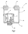
- the unlocking device for a control part 10 according to the perspective view Fig.1
- the actuating magnet 12 has a bobbin 14 with a coil winding, not shown, in which a cylinder or rod-like actuating member 16 is guided longitudinally movable.
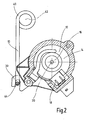
- the trained in the manner of a conventional electromagnet actuating magnet 12 is designed such that upon energization of the bobbin 14 via the connector 18, the actuating member 16 is pulled inward, ie in the direction of the Fig.2 seen towards the rear image plane.
- a non-illustrated return spring can reset the actuating member 16 so that this projecting with a predetermined projection on the front of the bobbin 14 including the front of the actuating magnet 12 at not energized bobbin 14.
- the actuating member 16 is thus arranged so as to be movable along a first axis 20.
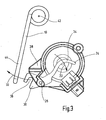
- the actuating member 16 is pulled by the actuating magnet 12 to the rear and thus releases a transverse to the first axis 20 pivoting path 22, which in the Figure 3 is shown with an arrow and along this pivoting path 22 pivots the control device 24 in the clockwise direction about a second axis 26 which is parallel to the first axis 20.
- the pertinent second axis 26 is formed, for example, as a pivot axis or pivot pin and with its free ends so far ends in a housing part 28, preferably made of a suitable plastic material, out.
- the control device 24 has a locking member 30 which unlocks by means of the actuating part 16 via the control device 24, the movement path 32, shown in the Figure 3 with an arrow for the control part 10 to be triggered.
- the locking part 30 at least partially surrounds the control part 10 and thus holds it in the locked position.
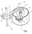
- the control device 24 has a pivot lever 34, as shown in the Figure 4 is shown in more detail.
- This pivot lever 34 is, as already stated, guided around the second axis 26 pivotally in the housing part 28, which is the simpler representation because of Figure 4 was omitted.
- the pivot lever 34 is at its one free end in the unactuated state of the actuating magnet 12 in abutment with the actuating part 16, wherein as shown in the Figure 4 just the operating member 16 is retracted into the bobbin 14 of the actuating magnet 12 and so far releases the pivoting path 22 for the pivot lever 34.
- in the retracted position of the operating part 16 forms this with its front substantially a flat front surface with the viewer of Figure 4 facing end side of the bobbin 14 from.
- the pivot lever 34 is still shown in its unactuated position, so far as the other part of the pivot lever 34, the control part 10 is held in the locked position.
- the locking part 30 of the control device 24 is designed in the manner of a jaw opening or mouth opening 36 and thus the pertinent locking part 30 can be arranged centrally, ie in a force-balanced manner in the middle of the device (cf. Fig.1 ),
- the pivot lever 34 has an axial offset point 38 in order to ensure the pertinent center arrangement can.
- the jaw or mouth opening 36 pivots clockwise about the pivot axis 26 from the locked position to the Fig.1 and 2 in an unlocked breastfeeding after the Figure 3 ,
- control part 10 provides a bow spring, preferably in the manner of a double bow spring 40 whose energy storage in the form of spring energy in the unlocked state allows pivoting along the path of movement 32 from the control device 24 for the control part 10, namely about a third axis 42, which in turn is parallel to the first and second axes 20,26. Due to the momentum of the control part 10 in the form of the double bow spring 40 so it is sufficient to trigger the actuating magnet 12 to make the unlocking so far externally controlled.
- the actuating magnet 12 is pot-shaped and has an annular coil body 14, the winding ends are connected to the connector 18 accordingly.
- an actuating part 16 of the bobbin 14 comprises a flat-cylindrical actuating rod, which has a similar cup shape to the annular bobbin 14 and is guided in this longitudinally movable.
- the pivot lever 34 is at its one free, the operating part 16 facing the end like a claw-like tapered provided with a curvature that at least partially follows the curvature of the outer periphery of the actuating part 16 (see also Fig.2 ).
- the said double bow spring 40 with its bow part 44 engages in the locking position in the locking part 30 of the control device 24, wherein the two, the double arrangement concerning round springs 46, the third axis 42 include the center.
- the blocking part 48 likewise consists of a bow spring 50 which, with its free spring ends 52 at least partially guided along the housing part 28, is movable into a position releasing the locking part 30.
- a bow spring 50 which, with its free spring ends 52 at least partially guided along the housing part 28, is movable into a position releasing the locking part 30.
- the bow spring 50 When in the Figure 5 shown position, the bow spring 50 is shown as a blocking part in its blocking position. If the unlocking process is triggered, then the locking member 30 snaps up and comes into the nip between the spring ends 52nd
- the unlocking device according to the invention can be used for a variety of applications, and instead of a control part 10 in the form of a double bow spring assembly 40, a simple spring (not shown) occur. Also, other technical components, such as parts of a roll bar system, of the jaw or mouth opening 36 of the locking member 30 hold, so that extent the scope is arbitrarily expandable.
- the solution according to the invention is also characterized in particular by the fact that the function control takes place via a single lever in the form of the pivoting lever 34.
Landscapes
- Engineering & Computer Science (AREA)
- Mechanical Engineering (AREA)
- Aviation & Aerospace Engineering (AREA)
- Transportation (AREA)
- Lock And Its Accessories (AREA)
- Replacement Of Web Rolls (AREA)
- Mechanical Control Devices (AREA)
- Special Wing (AREA)
- Stored Programmes (AREA)
- Control And Other Processes For Unpacking Of Materials (AREA)
- Seats For Vehicles (AREA)
- Pharmaceuticals Containing Other Organic And Inorganic Compounds (AREA)
Claims (4)
- Dispositif de déverrouillage pour commander pour la libérer une partie (10) de commande se trouvant à l'état verrouillé, comprenant un aimant (12) d'actionnement, qui a une partie (16) d'actionnement passant dans un corps (14) de bobine et/ou dans des parties d'enveloppe de l'aimant (12) d'actionnement, qui est déplaçable et qui libère dans une position d'actionnement un trajet (22) de déverrouillage pour un dispositif (24) de commande disposant d'une partie (30) de verrouillage qui déverrouillée, au moyen de la partie (16) d'actionnement par le dispositif (24) de commande, libère la voie (32) de déplacement pour la partie (10) de commande à commander, caractérisé en ce que la partie (30) de verrouillage passe dans la partie (18) d'enveloppe de l'aimant (12) d'actionnement et, en y étant maintenue au moyen d'une partie (48) de blocage dans la position déverrouillée correspondant à la libération de la partie (10) de commande, empêche un reverrouillage involontaire de la partie (10) de commande.
- Dispositif de déverrouillage suivant la revendication 1, caractérisé en ce que la partie (48) de blocage est formée par un ressort (50) à étrier, qui passe par ses extrémités (52) libres de ressort, au moins en partie, le long de la partie (28) d'enveloppe pour un mouvement entre une position de blocage, dans laquelle la partie (30) de verrouillage est maintenue dans la position déverrouillée par le ressort (50) à étrier, et une position dans laquelle la partie (30) de verrouillage est libérée pour un reverrouillage de la partie (10) de commande.
- Dispositif de déverrouillage suivant la revendication 2, caractérisé en ce que les extrémités (52) libres du ressort (50) à étrier forment, dans la position de blocage, un intervalle de serrage pour serrer la partie (30) de verrouillage se trouvant dans la position de déverrouillage.
- Dispositif de déverrouillage suivant la revendication 3, caractérisé en ce que, sur la partie (28) d'enveloppe, il y a des guidages (54) inclinés qui forment, lors du déplacement du ressort (50) à étrier, de la position de blocage à la position libérant la partie (30) de verrouillage, des surfaces de commande pour les extrémités (50) du ressort, qui écartent celles-ci l'une de l'autre et élargissent l'intervalle de serrage pour libérer la partie (30) de verrouillage en vue du retour dans la position verrouillant la partie (10) de commande.
Applications Claiming Priority (2)
| Application Number | Priority Date | Filing Date | Title |
|---|---|---|---|
| DE200510056816 DE102005056816A1 (de) | 2005-11-24 | 2005-11-24 | Entriegelungsvorrichtung für ein Steuerteil |
| PCT/EP2006/010212 WO2007059835A1 (fr) | 2005-11-24 | 2006-10-24 | Dispositif de deverrouillage |
Publications (2)
| Publication Number | Publication Date |
|---|---|
| EP1951546A1 EP1951546A1 (fr) | 2008-08-06 |
| EP1951546B1 true EP1951546B1 (fr) | 2009-04-22 |
Family
ID=37478855
Family Applications (2)
| Application Number | Title | Priority Date | Filing Date |
|---|---|---|---|
| EP06806480A Not-in-force EP1951546B1 (fr) | 2005-11-24 | 2006-10-24 | Dispositif de deverrouillage |
| EP06806479A Not-in-force EP1951545B1 (fr) | 2005-11-24 | 2006-10-24 | Dispositif de deverrouillage pour piece a commander |
Family Applications After (1)
| Application Number | Title | Priority Date | Filing Date |
|---|---|---|---|
| EP06806479A Not-in-force EP1951545B1 (fr) | 2005-11-24 | 2006-10-24 | Dispositif de deverrouillage pour piece a commander |
Country Status (8)
| Country | Link |
|---|---|
| US (2) | US8109544B2 (fr) |
| EP (2) | EP1951546B1 (fr) |
| JP (2) | JP4885974B2 (fr) |
| KR (2) | KR101254001B1 (fr) |
| CN (2) | CN101312849B (fr) |
| AT (2) | ATE429361T1 (fr) |
| DE (3) | DE102005056816A1 (fr) |
| WO (2) | WO2007059835A1 (fr) |
Families Citing this family (8)
| Publication number | Priority date | Publication date | Assignee | Title |
|---|---|---|---|---|
| DE102007036310A1 (de) | 2007-07-31 | 2009-02-05 | Hydac Electronic Gmbh | Sicherheitsvorrichtung |
| DE102007062080B4 (de) * | 2007-12-21 | 2012-09-27 | Hydac Electronic Gmbh | Vorrichtung zum Aktivieren einer sicherheitstechnischen Einrichtung, insbesondere einer Insassenschutzeinrichtung in einem Fahrzeug |
| DE102010031881A1 (de) * | 2010-07-21 | 2012-01-26 | Hydac Electronic Gmbh | Betätigungsvorrichtung für sicherheitstechnisch relevante Bauteile |
| DE102011013255B4 (de) * | 2011-03-07 | 2024-01-04 | Zf Airbag Germany Gmbh | Entriegelungsvorrichtung |
| DE102011120188B4 (de) * | 2011-12-05 | 2013-08-29 | Audi Ag | Notentriegelungseinrichtung für einenFahrzeug-Kofferraum |
| RU2620285C1 (ru) * | 2015-12-15 | 2017-05-24 | Федеральное государственное бюджетное образовательное учреждение высшего профессионального образования "Ульяновский государственный технический университет" | Транспортное средство повышенной безопасности |
| CN108973800B (zh) * | 2017-06-02 | 2022-09-20 | 布罗泽汽车部件制造科堡有限公司 | 用于车辆座椅的锁紧装置 |
| CN111098942B (zh) * | 2018-10-26 | 2021-04-16 | 北汽福田汽车股份有限公司 | 锁止机构、驾驶室后悬置锁止机构和车辆 |
Family Cites Families (25)
| Publication number | Priority date | Publication date | Assignee | Title |
|---|---|---|---|---|
| US1323007A (en) * | 1919-11-25 | brunette | ||
| US971423A (en) * | 1910-05-06 | 1910-09-27 | Frank Walters | Lock. |
| US1199199A (en) * | 1916-02-25 | 1916-09-26 | Universal Safety Lock Company | Electrically-controlled hood-lock. |
| US2381633A (en) * | 1941-10-15 | 1945-08-07 | Young Leonard Weare | Lock and fastening device |
| US2957721A (en) * | 1958-01-13 | 1960-10-25 | Security Storm Lock And Hardwa | Striker device |
| US3325203A (en) * | 1965-05-27 | 1967-06-13 | Overhead Door Corp | Sliding door lock |
| US4088354A (en) * | 1976-10-07 | 1978-05-09 | Litton Systems, Inc. | Door locking mechanism for self-cleaning oven |
| JPH0541165Y2 (fr) * | 1987-10-06 | 1993-10-19 | ||
| GB2223058B (en) * | 1988-09-21 | 1992-08-05 | Yale Security Prod Ltd | Electrically releasable door locking means |
| US5176417A (en) * | 1991-10-16 | 1993-01-05 | Applied Power Inc. | Tilt cab latch |
| US5263347A (en) * | 1992-09-21 | 1993-11-23 | Allbaugh Mark E | Remote control deadlock bolt for cars |
| CN1185512A (zh) * | 1996-12-20 | 1998-06-24 | 美国3M公司 | 开关箱遥控锁 |
| US6036241A (en) * | 1998-03-11 | 2000-03-14 | Maytag Corporation | Locking mechanism for an appliance door |
| WO1999061730A1 (fr) * | 1998-05-29 | 1999-12-02 | Slc Technologies, Inc. | Serrure electrique montee en rattrapage pour verrou mecanique |
| DE19830407B4 (de) * | 1998-07-08 | 2005-03-17 | Thomas Magnete Gmbh | Ver- und Entriegelungseinheit für ein Überrollschutzsystem |
| US6139073A (en) * | 1998-08-31 | 2000-10-31 | Westinghouse Air Brake Company | Lock assembly |
| US6290281B1 (en) * | 1999-05-26 | 2001-09-18 | Asc Incorporated | Power latch for an automotive vehicle convertible roof system |
| DE19949944C1 (de) * | 1999-10-16 | 2000-12-28 | Ise Gmbh | Haltevorrichtung für den Überrollkörper eines Überollschutzsystems |
| SE519101C2 (sv) * | 2000-05-16 | 2003-01-14 | Kongsberg Automotive Ab | Anordning vid nackskydd för motorfordon |
| EP1330584B1 (fr) * | 2000-11-01 | 2014-06-11 | Southco, Inc. | Dispositif de verrouillage |
| DE10215054B4 (de) * | 2002-04-05 | 2007-01-18 | Keiper Gmbh & Co.Kg | Kopfstütze für einen Fahrzeugsitz |
| US6712429B2 (en) * | 2002-06-07 | 2004-03-30 | Intier Automotive Inc. | Lost motion dual disc seat recliner assembly |
| KR101011079B1 (ko) | 2002-12-21 | 2011-01-25 | 카이퍼 게엠베하 운트 코. 카게 | 충격-작동식 머리받침 |
| US7416228B2 (en) * | 2003-09-08 | 2008-08-26 | Delta Consolidated Industries | Container with adjustable rotary lock |
| DE102004017688B4 (de) * | 2004-04-10 | 2010-02-11 | Itw Automotive Products Gmbh & Co. Kg | Kopfstütze für Automobilsitze |
-
2005
- 2005-11-24 DE DE200510056816 patent/DE102005056816A1/de not_active Withdrawn
-
2006
- 2006-10-24 DE DE200650003567 patent/DE502006003567D1/de active Active
- 2006-10-24 EP EP06806480A patent/EP1951546B1/fr not_active Not-in-force
- 2006-10-24 KR KR1020087012383A patent/KR101254001B1/ko not_active IP Right Cessation
- 2006-10-24 AT AT06806480T patent/ATE429361T1/de not_active IP Right Cessation
- 2006-10-24 CN CN2006800439614A patent/CN101312849B/zh not_active Expired - Fee Related
- 2006-10-24 JP JP2008541605A patent/JP4885974B2/ja not_active Expired - Fee Related
- 2006-10-24 AT AT06806479T patent/ATE429360T1/de not_active IP Right Cessation
- 2006-10-24 US US12/084,323 patent/US8109544B2/en not_active Expired - Fee Related
- 2006-10-24 CN CN2006800439934A patent/CN101312850B/zh not_active Expired - Fee Related
- 2006-10-24 US US12/085,173 patent/US8052179B2/en not_active Expired - Fee Related
- 2006-10-24 EP EP06806479A patent/EP1951545B1/fr not_active Not-in-force
- 2006-10-24 DE DE200650003566 patent/DE502006003566D1/de active Active
- 2006-10-24 KR KR1020087012398A patent/KR101254002B1/ko not_active IP Right Cessation
- 2006-10-24 WO PCT/EP2006/010212 patent/WO2007059835A1/fr active Application Filing
- 2006-10-24 WO PCT/EP2006/010211 patent/WO2007059834A1/fr active Application Filing
- 2006-10-24 JP JP2008541604A patent/JP5113073B2/ja not_active Expired - Fee Related
Also Published As
| Publication number | Publication date |
|---|---|
| US8109544B2 (en) | 2012-02-07 |
| EP1951546A1 (fr) | 2008-08-06 |
| WO2007059835A1 (fr) | 2007-05-31 |
| JP2009517566A (ja) | 2009-04-30 |
| EP1951545A1 (fr) | 2008-08-06 |
| DE102005056816A1 (de) | 2007-05-31 |
| JP5113073B2 (ja) | 2013-01-09 |
| CN101312850A (zh) | 2008-11-26 |
| JP4885974B2 (ja) | 2012-02-29 |
| CN101312849A (zh) | 2008-11-26 |
| CN101312850B (zh) | 2010-09-15 |
| US20090120146A1 (en) | 2009-05-14 |
| US20090151403A1 (en) | 2009-06-18 |
| WO2007059834A1 (fr) | 2007-05-31 |
| KR20080069627A (ko) | 2008-07-28 |
| ATE429360T1 (de) | 2009-05-15 |
| DE502006003567D1 (de) | 2009-06-04 |
| CN101312849B (zh) | 2010-10-13 |
| KR101254002B1 (ko) | 2013-04-12 |
| DE502006003566D1 (de) | 2009-06-04 |
| ATE429361T1 (de) | 2009-05-15 |
| KR20080069629A (ko) | 2008-07-28 |
| US8052179B2 (en) | 2011-11-08 |
| KR101254001B1 (ko) | 2013-04-12 |
| JP2009517259A (ja) | 2009-04-30 |
| EP1951545B1 (fr) | 2009-04-22 |
Similar Documents
| Publication | Publication Date | Title |
|---|---|---|
| EP1951546B1 (fr) | Dispositif de deverrouillage | |
| EP1941525B1 (fr) | Dispositif d' encliquetage pour entrainement a ressort accumulateur | |
| DE102005031264A1 (de) | Kopfstütze eines Kraftfahrzeugsitzes | |
| EP2704922A1 (fr) | Dispositif de verrouillage | |
| DE102013109931A1 (de) | Anordnung mit zumindest einem Federkörper und zumindest einem separat ausgebildeten Arretierteil | |
| EP2683577B1 (fr) | Dispositif de déverrouillage | |
| EP1160136B1 (fr) | Système de protection pour véhicules en cas de retournement | |
| DE102015109946A1 (de) | Kraftfahrzeugschloss | |
| EP1097064A1 (fr) | Module de retenue pour un vehicule a moteur | |
| DE102017103472A1 (de) | Kraftfahrzeugtürschloss | |
| EP3117057B1 (fr) | Système de fermeture de portière de véhicule automobile | |
| DE102008020433A1 (de) | Verriegelungseinrichtung für Kraftfahrzeuginnenraumkomponenten | |
| EP3474304B1 (fr) | Commutateur de sécurité | |
| EP3669848B1 (fr) | Système de retenue de rétracteur, procédé et utilisation d'un tel système de retenue de rétracteur, en particulier permettant de fixer des fauteuils roulants dans des véhicules | |
| DE102012025459A1 (de) | Anhängevorrichtung | |
| DE102005028928B4 (de) | Lösbare Halteeinrichtung zum Halten eines Überrollkörpers einer Überrollschutzvorrichtung eines Kraftfahrzeuges | |
| DE10127463B4 (de) | Sicherheitseinrichtung für Fahrzeuge | |
| WO2018087266A1 (fr) | Rétracteur de ceinture | |
| DE19930085C2 (de) | Kraftfahrzeugscheinwerfer | |
| DE102010031881A1 (de) | Betätigungsvorrichtung für sicherheitstechnisch relevante Bauteile | |
| DE102006026299B3 (de) | Vorrichtung zur Verriegelung eines ersten Fahrzeugteils an einem zweiten Fahrzeugteil | |
| EP3297890A1 (fr) | Dispositifs de blocage | |
| DE102014104115A1 (de) | Kraftfahrzeugschloss | |
| DE102007028031B4 (de) | Fahrgastsitz | |
| DE2307796C2 (de) | Schaltvorrichtung, insbesondere zum Betätigen eines Zünders, eines Ventils oder eines Schalters |
Legal Events
| Date | Code | Title | Description |
|---|---|---|---|
| PUAI | Public reference made under article 153(3) epc to a published international application that has entered the european phase |
Free format text: ORIGINAL CODE: 0009012 |
|
| 17P | Request for examination filed |
Effective date: 20080312 |
|
| AK | Designated contracting states |
Kind code of ref document: A1 Designated state(s): AT BE BG CH CY CZ DE DK EE ES FI FR GB GR HU IE IS IT LI LT LU LV MC NL PL PT RO SE SI SK TR |
|
| GRAP | Despatch of communication of intention to grant a patent |
Free format text: ORIGINAL CODE: EPIDOSNIGR1 |
|
| DAX | Request for extension of the european patent (deleted) | ||
| GRAS | Grant fee paid |
Free format text: ORIGINAL CODE: EPIDOSNIGR3 |
|
| GRAA | (expected) grant |
Free format text: ORIGINAL CODE: 0009210 |
|
| AK | Designated contracting states |
Kind code of ref document: B1 Designated state(s): AT BE BG CH CY CZ DE DK EE ES FI FR GB GR HU IE IS IT LI LT LU LV MC NL PL PT RO SE SI SK TR |
|
| REG | Reference to a national code |
Ref country code: GB Ref legal event code: FG4D Free format text: NOT ENGLISH |
|
| REG | Reference to a national code |
Ref country code: CH Ref legal event code: EP |
|
| REG | Reference to a national code |
Ref country code: IE Ref legal event code: FG4D |
|
| REF | Corresponds to: |
Ref document number: 502006003567 Country of ref document: DE Date of ref document: 20090604 Kind code of ref document: P |
|
| NLV1 | Nl: lapsed or annulled due to failure to fulfill the requirements of art. 29p and 29m of the patents act | ||
| PG25 | Lapsed in a contracting state [announced via postgrant information from national office to epo] |
Ref country code: FI Free format text: LAPSE BECAUSE OF FAILURE TO SUBMIT A TRANSLATION OF THE DESCRIPTION OR TO PAY THE FEE WITHIN THE PRESCRIBED TIME-LIMIT Effective date: 20090422 Ref country code: ES Free format text: LAPSE BECAUSE OF FAILURE TO SUBMIT A TRANSLATION OF THE DESCRIPTION OR TO PAY THE FEE WITHIN THE PRESCRIBED TIME-LIMIT Effective date: 20090802 Ref country code: PT Free format text: LAPSE BECAUSE OF FAILURE TO SUBMIT A TRANSLATION OF THE DESCRIPTION OR TO PAY THE FEE WITHIN THE PRESCRIBED TIME-LIMIT Effective date: 20090822 Ref country code: LT Free format text: LAPSE BECAUSE OF FAILURE TO SUBMIT A TRANSLATION OF THE DESCRIPTION OR TO PAY THE FEE WITHIN THE PRESCRIBED TIME-LIMIT Effective date: 20090422 |
|
| PG25 | Lapsed in a contracting state [announced via postgrant information from national office to epo] |
Ref country code: LV Free format text: LAPSE BECAUSE OF FAILURE TO SUBMIT A TRANSLATION OF THE DESCRIPTION OR TO PAY THE FEE WITHIN THE PRESCRIBED TIME-LIMIT Effective date: 20090422 Ref country code: IS Free format text: LAPSE BECAUSE OF FAILURE TO SUBMIT A TRANSLATION OF THE DESCRIPTION OR TO PAY THE FEE WITHIN THE PRESCRIBED TIME-LIMIT Effective date: 20090822 Ref country code: PL Free format text: LAPSE BECAUSE OF FAILURE TO SUBMIT A TRANSLATION OF THE DESCRIPTION OR TO PAY THE FEE WITHIN THE PRESCRIBED TIME-LIMIT Effective date: 20090422 Ref country code: SI Free format text: LAPSE BECAUSE OF FAILURE TO SUBMIT A TRANSLATION OF THE DESCRIPTION OR TO PAY THE FEE WITHIN THE PRESCRIBED TIME-LIMIT Effective date: 20090422 Ref country code: NL Free format text: LAPSE BECAUSE OF FAILURE TO SUBMIT A TRANSLATION OF THE DESCRIPTION OR TO PAY THE FEE WITHIN THE PRESCRIBED TIME-LIMIT Effective date: 20090422 Ref country code: SE Free format text: LAPSE BECAUSE OF FAILURE TO SUBMIT A TRANSLATION OF THE DESCRIPTION OR TO PAY THE FEE WITHIN THE PRESCRIBED TIME-LIMIT Effective date: 20090722 |
|
| REG | Reference to a national code |
Ref country code: IE Ref legal event code: FD4D |
|
| PG25 | Lapsed in a contracting state [announced via postgrant information from national office to epo] |
Ref country code: DK Free format text: LAPSE BECAUSE OF FAILURE TO SUBMIT A TRANSLATION OF THE DESCRIPTION OR TO PAY THE FEE WITHIN THE PRESCRIBED TIME-LIMIT Effective date: 20090422 Ref country code: RO Free format text: LAPSE BECAUSE OF FAILURE TO SUBMIT A TRANSLATION OF THE DESCRIPTION OR TO PAY THE FEE WITHIN THE PRESCRIBED TIME-LIMIT Effective date: 20090422 Ref country code: EE Free format text: LAPSE BECAUSE OF FAILURE TO SUBMIT A TRANSLATION OF THE DESCRIPTION OR TO PAY THE FEE WITHIN THE PRESCRIBED TIME-LIMIT Effective date: 20090422 Ref country code: IE Free format text: LAPSE BECAUSE OF FAILURE TO SUBMIT A TRANSLATION OF THE DESCRIPTION OR TO PAY THE FEE WITHIN THE PRESCRIBED TIME-LIMIT Effective date: 20090422 |
|
| PLBE | No opposition filed within time limit |
Free format text: ORIGINAL CODE: 0009261 |
|
| STAA | Information on the status of an ep patent application or granted ep patent |
Free format text: STATUS: NO OPPOSITION FILED WITHIN TIME LIMIT |
|
| 26N | No opposition filed |
Effective date: 20100125 |
|
| PG25 | Lapsed in a contracting state [announced via postgrant information from national office to epo] |
Ref country code: BG Free format text: LAPSE BECAUSE OF FAILURE TO SUBMIT A TRANSLATION OF THE DESCRIPTION OR TO PAY THE FEE WITHIN THE PRESCRIBED TIME-LIMIT Effective date: 20090722 |
|
| BERE | Be: lapsed |
Owner name: HYDAC ELECTRONIC G.M.B.H. Effective date: 20091031 |
|
| PG25 | Lapsed in a contracting state [announced via postgrant information from national office to epo] |
Ref country code: MC Free format text: LAPSE BECAUSE OF NON-PAYMENT OF DUE FEES Effective date: 20091031 |
|
| PG25 | Lapsed in a contracting state [announced via postgrant information from national office to epo] |
Ref country code: GR Free format text: LAPSE BECAUSE OF FAILURE TO SUBMIT A TRANSLATION OF THE DESCRIPTION OR TO PAY THE FEE WITHIN THE PRESCRIBED TIME-LIMIT Effective date: 20090723 Ref country code: BE Free format text: LAPSE BECAUSE OF NON-PAYMENT OF DUE FEES Effective date: 20091031 |
|
| PGFP | Annual fee paid to national office [announced via postgrant information from national office to epo] |
Ref country code: CZ Payment date: 20100806 Year of fee payment: 5 Ref country code: FR Payment date: 20101004 Year of fee payment: 5 Ref country code: SK Payment date: 20100806 Year of fee payment: 5 |
|
| PG25 | Lapsed in a contracting state [announced via postgrant information from national office to epo] |
Ref country code: AT Free format text: LAPSE BECAUSE OF NON-PAYMENT OF DUE FEES Effective date: 20091024 |
|
| PGFP | Annual fee paid to national office [announced via postgrant information from national office to epo] |
Ref country code: IT Payment date: 20101005 Year of fee payment: 5 |
|
| PG25 | Lapsed in a contracting state [announced via postgrant information from national office to epo] |
Ref country code: LU Free format text: LAPSE BECAUSE OF NON-PAYMENT OF DUE FEES Effective date: 20091024 |
|
| REG | Reference to a national code |
Ref country code: CH Ref legal event code: PL |
|
| GBPC | Gb: european patent ceased through non-payment of renewal fee |
Effective date: 20101024 |
|
| PG25 | Lapsed in a contracting state [announced via postgrant information from national office to epo] |
Ref country code: HU Free format text: LAPSE BECAUSE OF FAILURE TO SUBMIT A TRANSLATION OF THE DESCRIPTION OR TO PAY THE FEE WITHIN THE PRESCRIBED TIME-LIMIT Effective date: 20091023 |
|
| PG25 | Lapsed in a contracting state [announced via postgrant information from national office to epo] |
Ref country code: LI Free format text: LAPSE BECAUSE OF NON-PAYMENT OF DUE FEES Effective date: 20101031 Ref country code: CH Free format text: LAPSE BECAUSE OF NON-PAYMENT OF DUE FEES Effective date: 20101031 |
|
| PG25 | Lapsed in a contracting state [announced via postgrant information from national office to epo] |
Ref country code: GB Free format text: LAPSE BECAUSE OF NON-PAYMENT OF DUE FEES Effective date: 20101024 Ref country code: TR Free format text: LAPSE BECAUSE OF FAILURE TO SUBMIT A TRANSLATION OF THE DESCRIPTION OR TO PAY THE FEE WITHIN THE PRESCRIBED TIME-LIMIT Effective date: 20090422 |
|
| PG25 | Lapsed in a contracting state [announced via postgrant information from national office to epo] |
Ref country code: CY Free format text: LAPSE BECAUSE OF FAILURE TO SUBMIT A TRANSLATION OF THE DESCRIPTION OR TO PAY THE FEE WITHIN THE PRESCRIBED TIME-LIMIT Effective date: 20090422 |
|
| REG | Reference to a national code |
Ref country code: SK Ref legal event code: MM4A Ref document number: E 5482 Country of ref document: SK Effective date: 20111024 |
|
| REG | Reference to a national code |
Ref country code: FR Ref legal event code: ST Effective date: 20120629 |
|
| PG25 | Lapsed in a contracting state [announced via postgrant information from national office to epo] |
Ref country code: SK Free format text: LAPSE BECAUSE OF NON-PAYMENT OF DUE FEES Effective date: 20111024 Ref country code: CZ Free format text: LAPSE BECAUSE OF NON-PAYMENT OF DUE FEES Effective date: 20111024 |
|
| PG25 | Lapsed in a contracting state [announced via postgrant information from national office to epo] |
Ref country code: FR Free format text: LAPSE BECAUSE OF NON-PAYMENT OF DUE FEES Effective date: 20111102 Ref country code: IT Free format text: LAPSE BECAUSE OF NON-PAYMENT OF DUE FEES Effective date: 20111024 |
|
| PGFP | Annual fee paid to national office [announced via postgrant information from national office to epo] |
Ref country code: DE Payment date: 20131025 Year of fee payment: 8 |
|
| REG | Reference to a national code |
Ref country code: DE Ref legal event code: R119 Ref document number: 502006003567 Country of ref document: DE |
|
| PG25 | Lapsed in a contracting state [announced via postgrant information from national office to epo] |
Ref country code: DE Free format text: LAPSE BECAUSE OF NON-PAYMENT OF DUE FEES Effective date: 20150501 |