EP1951546B1 - Unlocking device - Google Patents
Unlocking device Download PDFInfo
- Publication number
- EP1951546B1 EP1951546B1 EP06806480A EP06806480A EP1951546B1 EP 1951546 B1 EP1951546 B1 EP 1951546B1 EP 06806480 A EP06806480 A EP 06806480A EP 06806480 A EP06806480 A EP 06806480A EP 1951546 B1 EP1951546 B1 EP 1951546B1
- Authority
- EP
- European Patent Office
- Prior art keywords
- locking
- control
- actuating
- blocking
- unlocking
- Prior art date
- Legal status (The legal status is an assumption and is not a legal conclusion. Google has not performed a legal analysis and makes no representation as to the accuracy of the status listed.)
- Not-in-force
Links
Images

Classifications
-
- B—PERFORMING OPERATIONS; TRANSPORTING
- B60—VEHICLES IN GENERAL
- B60N—SEATS SPECIALLY ADAPTED FOR VEHICLES; VEHICLE PASSENGER ACCOMMODATION NOT OTHERWISE PROVIDED FOR
- B60N2/00—Seats specially adapted for vehicles; Arrangement or mounting of seats in vehicles
- B60N2/24—Seats specially adapted for vehicles; Arrangement or mounting of seats in vehicles for particular purposes or particular vehicles
- B60N2/42—Seats specially adapted for vehicles; Arrangement or mounting of seats in vehicles for particular purposes or particular vehicles the seat constructed to protect the occupant from the effect of abnormal g-forces, e.g. crash or safety seats
-
- B—PERFORMING OPERATIONS; TRANSPORTING
- B60—VEHICLES IN GENERAL
- B60R—VEHICLES, VEHICLE FITTINGS, OR VEHICLE PARTS, NOT OTHERWISE PROVIDED FOR
- B60R21/00—Arrangements or fittings on vehicles for protecting or preventing injuries to occupants or pedestrians in case of accidents or other traffic risks
- B60R21/02—Occupant safety arrangements or fittings, e.g. crash pads
- B60R21/13—Roll-over protection
-
- B—PERFORMING OPERATIONS; TRANSPORTING
- B60—VEHICLES IN GENERAL
- B60N—SEATS SPECIALLY ADAPTED FOR VEHICLES; VEHICLE PASSENGER ACCOMMODATION NOT OTHERWISE PROVIDED FOR
- B60N2/00—Seats specially adapted for vehicles; Arrangement or mounting of seats in vehicles
- B60N2/80—Head-rests
- B60N2/888—Head-rests with arrangements for protecting against abnormal g-forces, e.g. by displacement of the head-rest
-
- B—PERFORMING OPERATIONS; TRANSPORTING
- B60—VEHICLES IN GENERAL
- B60R—VEHICLES, VEHICLE FITTINGS, OR VEHICLE PARTS, NOT OTHERWISE PROVIDED FOR
- B60R21/00—Arrangements or fittings on vehicles for protecting or preventing injuries to occupants or pedestrians in case of accidents or other traffic risks
- B60R21/02—Occupant safety arrangements or fittings, e.g. crash pads
- B60R21/13—Roll-over protection
- B60R2021/132—Roll bars for convertible vehicles
- B60R2021/134—Roll bars for convertible vehicles movable from a retracted to a protection position
- B60R2021/135—Roll bars for convertible vehicles movable from a retracted to a protection position automatically during an accident
-
- Y—GENERAL TAGGING OF NEW TECHNOLOGICAL DEVELOPMENTS; GENERAL TAGGING OF CROSS-SECTIONAL TECHNOLOGIES SPANNING OVER SEVERAL SECTIONS OF THE IPC; TECHNICAL SUBJECTS COVERED BY FORMER USPC CROSS-REFERENCE ART COLLECTIONS [XRACs] AND DIGESTS
- Y10—TECHNICAL SUBJECTS COVERED BY FORMER USPC
- Y10S—TECHNICAL SUBJECTS COVERED BY FORMER USPC CROSS-REFERENCE ART COLLECTIONS [XRACs] AND DIGESTS
- Y10S292/00—Closure fasteners
- Y10S292/61—Spring devices
-
- Y—GENERAL TAGGING OF NEW TECHNOLOGICAL DEVELOPMENTS; GENERAL TAGGING OF CROSS-SECTIONAL TECHNOLOGIES SPANNING OVER SEVERAL SECTIONS OF THE IPC; TECHNICAL SUBJECTS COVERED BY FORMER USPC CROSS-REFERENCE ART COLLECTIONS [XRACs] AND DIGESTS
- Y10—TECHNICAL SUBJECTS COVERED BY FORMER USPC
- Y10T—TECHNICAL SUBJECTS COVERED BY FORMER US CLASSIFICATION
- Y10T292/00—Closure fasteners
- Y10T292/08—Bolts
- Y10T292/1043—Swinging
- Y10T292/1075—Operating means
- Y10T292/1082—Motor
-
- Y—GENERAL TAGGING OF NEW TECHNOLOGICAL DEVELOPMENTS; GENERAL TAGGING OF CROSS-SECTIONAL TECHNOLOGIES SPANNING OVER SEVERAL SECTIONS OF THE IPC; TECHNICAL SUBJECTS COVERED BY FORMER USPC CROSS-REFERENCE ART COLLECTIONS [XRACs] AND DIGESTS
- Y10—TECHNICAL SUBJECTS COVERED BY FORMER USPC
- Y10T—TECHNICAL SUBJECTS COVERED BY FORMER US CLASSIFICATION
- Y10T292/00—Closure fasteners
- Y10T292/11—Magnetic
-
- Y—GENERAL TAGGING OF NEW TECHNOLOGICAL DEVELOPMENTS; GENERAL TAGGING OF CROSS-SECTIONAL TECHNOLOGIES SPANNING OVER SEVERAL SECTIONS OF THE IPC; TECHNICAL SUBJECTS COVERED BY FORMER USPC CROSS-REFERENCE ART COLLECTIONS [XRACs] AND DIGESTS
- Y10—TECHNICAL SUBJECTS COVERED BY FORMER USPC
- Y10T—TECHNICAL SUBJECTS COVERED BY FORMER US CLASSIFICATION
- Y10T292/00—Closure fasteners
- Y10T292/68—Keepers
-
- Y—GENERAL TAGGING OF NEW TECHNOLOGICAL DEVELOPMENTS; GENERAL TAGGING OF CROSS-SECTIONAL TECHNOLOGIES SPANNING OVER SEVERAL SECTIONS OF THE IPC; TECHNICAL SUBJECTS COVERED BY FORMER USPC CROSS-REFERENCE ART COLLECTIONS [XRACs] AND DIGESTS
- Y10—TECHNICAL SUBJECTS COVERED BY FORMER USPC
- Y10T—TECHNICAL SUBJECTS COVERED BY FORMER US CLASSIFICATION
- Y10T70/00—Locks
- Y10T70/50—Special application
-
- Y—GENERAL TAGGING OF NEW TECHNOLOGICAL DEVELOPMENTS; GENERAL TAGGING OF CROSS-SECTIONAL TECHNOLOGIES SPANNING OVER SEVERAL SECTIONS OF THE IPC; TECHNICAL SUBJECTS COVERED BY FORMER USPC CROSS-REFERENCE ART COLLECTIONS [XRACs] AND DIGESTS
- Y10—TECHNICAL SUBJECTS COVERED BY FORMER USPC
- Y10T—TECHNICAL SUBJECTS COVERED BY FORMER US CLASSIFICATION
- Y10T70/00—Locks
- Y10T70/70—Operating mechanism
- Y10T70/7051—Using a powered device [e.g., motor]
- Y10T70/7057—Permanent magnet
Definitions
- the invention relates to an unlocking device to control a located in the locked state control part for its release, with an actuating magnet which, guided in a bobbin and / or in housing parts of the actuating magnet, an actuating part which is movable and in an operating position a Entriegelungsweg releases for a control device which has a locking part which, unlocked by means of the actuating part via the control device, releases the path of movement for the control part to be triggered, such as, for example DE 10 215 054 is known.
- unlocking devices can be used for a variety of applications.
- unlocking devices with actuating magnets are preferable because the pertinent actuating magnet is also reliable in everyday use, such as occurring vibrations or shocks, functionally reliable in use.
- the unlocking device according to the invention can be unlocked especially in the automotive sector safety-relevant components and bring to function, be it in the form of a roll bar to be erected, be it in the form of a moving headrest in the event of a crash to thus reducing the free impact between the occiput of the seat occupant and head impact area on the headrest, etc.
- the actuating magnet can be accommodated with operating part and movable control device in a very small space, so that can leave the pertinent devices to save space within motor vehicles. Due to the space-saving design, such unlocking devices can also be used there directly at the point of a tripping operation, where hitherto in the prior art, possibly only consuming to handle cables or Bowden cables over longer distances have accomplished the tripping operation.
- the invention has for its object to provide an unlocking available, in which the risk of such loss of Functional safety of an associated safety device is avoided.
- the peculiarity of the invention consists in the fact that a blocking part is provided for the guided in the housing part of the actuating magnet locking part, which holds the locking part in the release of the control part corresponding unlocked position, thereby preventing unwanted re-locking of the control part.
- the blocking part is formed by a bow spring, which is guided with its free spring ends at least partially along the housing part for movement between the blocking position, in which the locking member is held by the bow spring in the unlocked position, and a position in the locking part is released for re-locking the control part.
- the arrangement may preferably be made such that the bow spring is accessible for manual displacement from the blocking position out.
- the bow spring may be shaped so that the free spring ends in the blocking position between them form a nip for clamping the locking member located in the unlocking position.
- Angular guides are provided which, upon movement of the bow spring from the blocking position to the locking member releasing position, form control surfaces for the spring ends which spread them apart and expand the nip to release the locking member for return to the control member locking position.
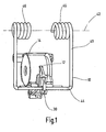
- the unlocking device for a control part 10 according to the perspective view Fig.1
- the actuating magnet 12 has a bobbin 14 with a coil winding, not shown, in which a cylinder or rod-like actuating member 16 is guided longitudinally movable.
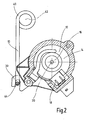
- the trained in the manner of a conventional electromagnet actuating magnet 12 is designed such that upon energization of the bobbin 14 via the connector 18, the actuating member 16 is pulled inward, ie in the direction of the Fig.2 seen towards the rear image plane.
- a non-illustrated return spring can reset the actuating member 16 so that this projecting with a predetermined projection on the front of the bobbin 14 including the front of the actuating magnet 12 at not energized bobbin 14.
- the actuating member 16 is thus arranged so as to be movable along a first axis 20.
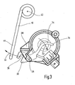
- the actuating member 16 is pulled by the actuating magnet 12 to the rear and thus releases a transverse to the first axis 20 pivoting path 22, which in the Figure 3 is shown with an arrow and along this pivoting path 22 pivots the control device 24 in the clockwise direction about a second axis 26 which is parallel to the first axis 20.
- the pertinent second axis 26 is formed, for example, as a pivot axis or pivot pin and with its free ends so far ends in a housing part 28, preferably made of a suitable plastic material, out.
- the control device 24 has a locking member 30 which unlocks by means of the actuating part 16 via the control device 24, the movement path 32, shown in the Figure 3 with an arrow for the control part 10 to be triggered.
- the locking part 30 at least partially surrounds the control part 10 and thus holds it in the locked position.
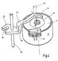
- the control device 24 has a pivot lever 34, as shown in the Figure 4 is shown in more detail.
- This pivot lever 34 is, as already stated, guided around the second axis 26 pivotally in the housing part 28, which is the simpler representation because of Figure 4 was omitted.
- the pivot lever 34 is at its one free end in the unactuated state of the actuating magnet 12 in abutment with the actuating part 16, wherein as shown in the Figure 4 just the operating member 16 is retracted into the bobbin 14 of the actuating magnet 12 and so far releases the pivoting path 22 for the pivot lever 34.
- in the retracted position of the operating part 16 forms this with its front substantially a flat front surface with the viewer of Figure 4 facing end side of the bobbin 14 from.
- the pivot lever 34 is still shown in its unactuated position, so far as the other part of the pivot lever 34, the control part 10 is held in the locked position.
- the locking part 30 of the control device 24 is designed in the manner of a jaw opening or mouth opening 36 and thus the pertinent locking part 30 can be arranged centrally, ie in a force-balanced manner in the middle of the device (cf. Fig.1 ),
- the pivot lever 34 has an axial offset point 38 in order to ensure the pertinent center arrangement can.
- the jaw or mouth opening 36 pivots clockwise about the pivot axis 26 from the locked position to the Fig.1 and 2 in an unlocked breastfeeding after the Figure 3 ,
- control part 10 provides a bow spring, preferably in the manner of a double bow spring 40 whose energy storage in the form of spring energy in the unlocked state allows pivoting along the path of movement 32 from the control device 24 for the control part 10, namely about a third axis 42, which in turn is parallel to the first and second axes 20,26. Due to the momentum of the control part 10 in the form of the double bow spring 40 so it is sufficient to trigger the actuating magnet 12 to make the unlocking so far externally controlled.
- the actuating magnet 12 is pot-shaped and has an annular coil body 14, the winding ends are connected to the connector 18 accordingly.
- an actuating part 16 of the bobbin 14 comprises a flat-cylindrical actuating rod, which has a similar cup shape to the annular bobbin 14 and is guided in this longitudinally movable.
- the pivot lever 34 is at its one free, the operating part 16 facing the end like a claw-like tapered provided with a curvature that at least partially follows the curvature of the outer periphery of the actuating part 16 (see also Fig.2 ).
- the said double bow spring 40 with its bow part 44 engages in the locking position in the locking part 30 of the control device 24, wherein the two, the double arrangement concerning round springs 46, the third axis 42 include the center.
- the blocking part 48 likewise consists of a bow spring 50 which, with its free spring ends 52 at least partially guided along the housing part 28, is movable into a position releasing the locking part 30.
- a bow spring 50 which, with its free spring ends 52 at least partially guided along the housing part 28, is movable into a position releasing the locking part 30.
- the bow spring 50 When in the Figure 5 shown position, the bow spring 50 is shown as a blocking part in its blocking position. If the unlocking process is triggered, then the locking member 30 snaps up and comes into the nip between the spring ends 52nd
- the unlocking device according to the invention can be used for a variety of applications, and instead of a control part 10 in the form of a double bow spring assembly 40, a simple spring (not shown) occur. Also, other technical components, such as parts of a roll bar system, of the jaw or mouth opening 36 of the locking member 30 hold, so that extent the scope is arbitrarily expandable.
- the solution according to the invention is also characterized in particular by the fact that the function control takes place via a single lever in the form of the pivoting lever 34.
Abstract
Description
Die Erfindung betrifft eine Entriegelungsvorrichtung, um ein in verriegeltem Zustand befindliches Steuerteil für seine Freigabe anzusteuern, mit einem Betätigungsmagneten, der, in einem Spulenkörper und/oder in Gehäuseteilen des Betätigungsmagneten geführt, ein Betätigungsteil aufweist, das verfahrbar ist und das in einer Betätigungsstellung einen Entriegelungsweg für eine Steuereinrichtung freigibt, die über ein Verriegelungsteil verfügt, das, mittels des Betätigungsteils über die Steuereinrichtung entriegelt, die Bewegungsbahn für das anzusteuernde Steuerteil freigibt, wie z.B. aus
Dahingehende Entriegelungsvorrichtungen können für eine Vielzahl von Anwendungsfällen eingesetzt werden. Insbesondere dort, wo es darauf ankommt, gezielt und funktionssicher einen Auslösevorgang für ein technisches Bauteil zu realisieren, sind Entriegelungsvorrichtungen mit Betätigungsmagneten vorzuziehen, da der dahingehende Betätigungsmagnet auch im rauhen Alltagsbetrieb, etwa bei auftretenden Schwingungen oder Stößen, erfahrungsgemäß funktionssicher im Gebrauch ist. Mit der erfindungsgemäßen Entriegelungsvorrichtung lassen sich insbesondere im Kraftfahrzeugbereich sicherheitstechnisch relevante Bauteile entriegeln und zur Funktion bringen, sei es in Form eines aufzustellenden Überrollbügels, sei es in Form einer im Crashfall sich nach vorne bewegenden Kopfstütze, um dergestalt den freien Auftreffweg zwischen Hinterkopf des Sitzbenutzers und Kopfauftreff-Fläche an der Kopfstütze zu verringern, etc..These unlocking devices can be used for a variety of applications. In particular, where it depends on targeted and reliable operation to realize a triggering operation for a technical component, unlocking devices with actuating magnets are preferable because the pertinent actuating magnet is also reliable in everyday use, such as occurring vibrations or shocks, functionally reliable in use. With the unlocking device according to the invention can be unlocked especially in the automotive sector safety-relevant components and bring to function, be it in the form of a roll bar to be erected, be it in the form of a moving headrest in the event of a crash to thus reducing the free impact between the occiput of the seat occupant and head impact area on the headrest, etc.
Bei derartigen Entriegelungsvorrichtungen läßt sich der Betätigungsmagnet mit Betätigungsteil und bewegbarer Steuereinrichtung auf sehr kleinem Bauraum unterbringen, so dass sich die dahingehenden Vorrichtungen platzsparend innerhalb von Kraftfahrzeugen unterbringen lassen. Aufgrund des platzsparenden Aufbaus lassen sich solche Entriegelungsvorrichtungen auch dort unmittelbar an der Stelle eines Auslösevorganges einsetzen, wo bisher im Stand der Technik gegebenenfalls erst aufwendig zu handhabende Seil- oder Bowdenzüge über größere Wegstrecken den Auslösevorgang bewerkstelligt haben.In such Entriegelungsvorrichtungen the actuating magnet can be accommodated with operating part and movable control device in a very small space, so that can leave the pertinent devices to save space within motor vehicles. Due to the space-saving design, such unlocking devices can also be used there directly at the point of a tripping operation, where hitherto in the prior art, possibly only consuming to handle cables or Bowden cables over longer distances have accomplished the tripping operation.
Andererseits besteht bei sicherheitsrelevanten Anwendungen derartiger Entriegelungsvorrichtungen jedoch die Gefahr des Verlustes der Funktionssicherheit. Nach einem Auslösevorgang, bei dem durch Ansteuerung des Steuerteils die betreffende Sicherheitseinrichtung aktiviert wurde, ist es in vielen Fällen erforderlich, dass, um Funktionssicherheit zu gewährleisten, die Sicherheitseinrichtung selbst oder deren Teile vor einer erneuten Inbetriebnahme erst gegen Neuteile ausgetauscht werden. Mit anderen Worten gesagt, besteht die Gefahr, dass versehentlich eine bereits aktivierte Sicherheitseinrichtung in die Ausgangslage zurückgebracht, das Steuerteil mittels der Entriegelungsvorrichtung erneut in den verriegelten Zustand gebracht und die nach erfolgter Aktivierung nicht mehr funktionssichere Sicherheitseinrichtung wieder "scharf gemacht" wird.On the other hand, there is the risk of loss of reliability in safety-related applications of such unlocking devices. After a tripping operation, in which by activating the control part, the relevant safety device has been activated, it is necessary in many cases that, in order to ensure functional safety, the safety device itself or its parts are exchanged for new parts before re-commissioning. In other words, there is a risk that inadvertently returned to an already activated safety device in the starting position, the control part brought by means of the unlocking device again in the locked state and the after activation no longer functionally reliable safety device is "armed" again.
Der Erfindung liegt die Aufgabe zugrunde, eine Entriegelungsvorrichtung zur Verfügung zu stellen, bei der die Gefahr eines derartigen Verlustes der Funktionssicherheit einer zugeordneten Sicherheitseinrichtung vermieden ist.The invention has for its object to provide an unlocking available, in which the risk of such loss of Functional safety of an associated safety device is avoided.
Erfindungsgemäß ist diese Aufgabe durch eine Entriegelungsvorrichtung gelöst, die die Merkmale des Patentanspruches 1 in seiner Gesamtheit aufweist.According to the invention this object is achieved by an unlocking device having the features of claim 1 in its entirety.
Die Besonderheit der Erfindung besteht danach darin, dass für das im Gehäuseteil des Betätigungsmagneten geführte Verriegelungsteil ein Blockierteil vorgesehen ist, welches das Verriegelungsteil in der der Freigabe des Steuerteils entsprechenden entriegelten Stellung hält und dadurch ein ungewolltes erneutes Verriegeln des Steuerteils verhindert.The peculiarity of the invention consists in the fact that a blocking part is provided for the guided in the housing part of the actuating magnet locking part, which holds the locking part in the release of the control part corresponding unlocked position, thereby preventing unwanted re-locking of the control part.
Bei einem besonders vorteilhaften Ausführungsbeispiel ist das Blockierteil durch eine Bügelfeder gebildet, die mit ihren freien Federenden zumindest teilweise längs des Gehäuseteils für eine Bewegung zwischen Blockierstellung, in der das Verriegelungsteil durch die Bügelfeder in der entriegelten Stellung gehalten ist, und einer Stellung geführt ist, in der das Verriegelungsteil für ein erneutes Verriegeln des Steuerteils freigegeben ist. Hierbei kann die Anordnung vorzugsweise so getroffen sein, dass die Bügelfeder für ein von Hand erfolgendes Verschieben aus der Blockierstellung heraus zugänglich ist.In a particularly advantageous embodiment, the blocking part is formed by a bow spring, which is guided with its free spring ends at least partially along the housing part for movement between the blocking position, in which the locking member is held by the bow spring in the unlocked position, and a position in the locking part is released for re-locking the control part. In this case, the arrangement may preferably be made such that the bow spring is accessible for manual displacement from the blocking position out.
Die Bügelfeder kann so geformt sein, dass die freien Federenden bei der Blockierstellung zwischen sich einen Klemmspalt zum Festklemmen des in der Entriegelungsposition befindlichen Verriegelungsteiles bilden.The bow spring may be shaped so that the free spring ends in the blocking position between them form a nip for clamping the locking member located in the unlocking position.
Bei Ausführungsbeispielen, die sich durch eine eine einfache und bequeme Handhabung ermöglichende Bauweise auszeichnen, sind am Gehäuseteil Schrägführungen vorhanden, die bei der Bewegung der Bügelfeder aus der Blockierstellung in die das Verriegelungsteil freigebende Stellung Steuerflächen für die Federenden bilden, die diese voneinander weg spreizen und den Klemmspalt erweitern, um das Verriegelungsteil für das Rückführen in die das Steuerteil verriegelnde Stellung freizugeben.In embodiments, which are characterized by a simple and convenient handling enabling construction, are on the housing part Angular guides are provided which, upon movement of the bow spring from the blocking position to the locking member releasing position, form control surfaces for the spring ends which spread them apart and expand the nip to release the locking member for return to the control member locking position.
Im folgenden wird die erfindungsgemäße Entriegelungsvorrichtung für ein Steuerteil gemäß einem Ausführungsbeispiel nach der Zeichnung näher erläutert. Dabei zeigen in prinzipieller und nicht maßstäblicher Darstellung die
- Fig.1
- in perspektivischer Anordnung eine Vorderansicht auf die wesentlichen Teile der erfindungsgemäßen Vorrichtung;
- Fig.2 und 3
- einmal im verriegelten, einmal im entriegelten Zustand die Vorrichtung nach der
Fig.1 von der Seite her gesehen; - Fig.4
- eine perspektivische Draufsicht auf den Betätigungsmagneten mit Sperrklinke;
- Fig. 5
- ein teilweise aufgeschnittenes Gehäuse der Vorrichtung mit eingesetztem Blockierelement.
- Fig.1
- in a perspective arrangement a front view of the essential parts of the device according to the invention;
- Fig.2 and 3
- Once in the locked, once in the unlocked state, the device after the
Fig.1 seen from the side; - Figure 4
- a top perspective view of the actuating magnet with pawl;
- Fig. 5
- a partially cut housing of the device with inserted blocking element.
Die Entriegelungsvorrichtung für ein Steuerteil 10 nach der perspektivischen Ansicht gemäß
Der in der Art eines üblichen Elektromagneten ausgebildete Betätigungsmagnet 12 ist derart ausgelegt, dass bei Bestromung des Spulenkörpers 14 über den Anschlußstecker 18 das Betätigungsteil 16 nach innen gezogen wird, also in Blickrichtung auf die
In der in der
Die Steuereinrichtung 24 weist einen Schwenkhebel 34 auf, wie er in der
Gemäß der Darstellung nach der
Bei bestimmten Anwendungsaufgaben wäre es auch denkbar, beispielsweise an der zweiten Achse 26 selbst eine Drehfeder od. dgl. anzubringen, um insoweit den Schwenkhebel längs des Schwenkweges 22 zu bewegen, sobald das Betätigungsteil 16 in den Spulenkörper 14 eingezogen ist. Im vorliegenden Fall wird jedoch im betätigten Zustand des Betätigungsmagneten 12 das Steuerteil 10 mittels eines Energiespeichers die Entriegelung für den Schwenkhebel 34 von außen her veranlassen, der dann insoweit um die zweite Achse 26 in die Entriegelungsstellung verschwenkt. Hierfür sieht das Steuerteil 10 eine Bügelfeder, vorzugsweise in der Art einer Doppel-Bügelfeder 40 vor, deren Energiespeicher in Form von Federenergie im entriegelten Zustand ein Wegschwenken längs der Bewegungsbahn 32 aus der Steuereinrichtung 24 für das Steuerteil 10 ermöglicht, und zwar um eine dritte Achse 42, die wiederum parallel zu der ersten und zweiten Achse 20,26 verläuft. Aufgrund der Eigendynamik des Steuerteils 10 in Form der Doppel-Bügelfeder 40 genügt es also, den Betätigungsmagneten 12 auszulösen, um die Entriegelung insoweit fremdgesteuert vornehmen zu können.In certain application tasks, it would also be conceivable, for example, on the
Der Betätigungsmagnet 12 ist topfartig ausgebildet und weist insoweit einen ringförmigen Spulenkörper 14 auf, dessen Wicklungsenden an den Anschlußstecker 18 entsprechend angeschlossen sind. Als Betätigungsteil 16 umfaßt der Spulenkörper 14 eine flachzylindrische Betätigungsstange, die vergleichbar eine Topfform aufweist zu dem ringförmigen Spulenkörper 14 und in diesem längsverfahrbar geführt ist. Wie des weiteren die
Wird gemäß der Darstellung nach der
Das Blockierteil 48 besteht gleichfalls aus einer Bügelfeder 50, die mit ihren freien Federenden 52 zumindest teilweise längs des Gehäuseteils 28 geführt in eine das Verriegelungsteil 30 freigebende Stellung bewegbar ist. Um die dahingehenden Verhältnisse besser zu verdeutlichen, ist in der
Die Federenden 52 klemmen dann zwischen sich einen Teil des Verriegelungsteils 30 derart ein, dass dieser in der Entriegelungsposition nach der
Die erfindungsgemäße Entriegelungseinrichtung läßt sich für eine Vielzahl an Anwendungen einsetzen, und anstelle eines Steuerteils 10 in Form einer Doppel-Bügelfederanordnung 40 kann auch eine einfache Feder (nicht dargestellt) treten. Auch lassen sich sonstige technische Komponenten, wie beispielsweise Teile eines Überrollbügelsystems, von der Klauen- oder Maulöffnung 36 des Verriegelungsteils 30 halten, so dass insoweit der Anwendungsbereich beliebig erweiterbar ist.The unlocking device according to the invention can be used for a variety of applications, and instead of a
Die erfindungsgemäße Lösung zeichnet sich insbesondere auch noch dadurch aus, dass die Funktionssteuerung über einen Einhebel erfolgt in Form des Schwenkhebels 34.The solution according to the invention is also characterized in particular by the fact that the function control takes place via a single lever in the form of the pivoting
Claims (4)
- An unlocking device in order to actuate a control part (10) in the locked state for its release, with an actuating magnet (12) which, guided in a coil element (14) and/or in housing parts of the actuating magnet (12), has an actuating part (16) which can be displaced and which releases, in an actuation position, an unlocking path (22) for a control device (24) which has a locking part (30) which, when unlocked by means of the actuating part (16) via the control device (24), releases the trajectory (32) for the control part (10) to be actuated, characterised in that the locking part (30) is guided within the housing part (28) of the actuating magnet (12) and, held on the latter by means of a blocking part (48) in the unlocked position corresponding to the release of the control part (10), prevents unwanted re-locking of the control part (10).
- The unlocking device according to Claim 1, characterised in that the blocking part (48) is formed by a bow spring (50) which with its free spring ends (52) is guided at least partially along the housing part (28) for a movement between the blocking position, in which the locking part (30) is held by the bow spring (50) in the unlocked position, and a position in which the locking part (30) is released for re-locking of the control part (10).
- The unlocking device according to Claim 2, characterised in that in the blocking position the free spring ends (52) of the bow spring (50) form between them a clamping gap for securely clamping the locking part (30) located in the unlocked position.
- The unlocking device according to Claim 3, characterised in that on the housing part (28) inclined guides (54) are provided which, upon movement of the bow spring (50) from the blocking position into the position releasing the locking part (30), form control surfaces for the spring ends (52) which force the latter apart from one another and extend the camping gap in order to release the locking part (30) for returning to the position locking the control part (10).
Applications Claiming Priority (2)
| Application Number | Priority Date | Filing Date | Title |
|---|---|---|---|
| DE200510056816 DE102005056816A1 (en) | 2005-11-24 | 2005-11-24 | Releasing device for control section, has control device pivotably arranged parallel to axis and including locking part that is released by using operating part by control device which releases moving web for control part to be controlled |
| PCT/EP2006/010212 WO2007059835A1 (en) | 2005-11-24 | 2006-10-24 | Unlocking device |
Publications (2)
| Publication Number | Publication Date |
|---|---|
| EP1951546A1 EP1951546A1 (en) | 2008-08-06 |
| EP1951546B1 true EP1951546B1 (en) | 2009-04-22 |
Family
ID=37478855
Family Applications (2)
| Application Number | Title | Priority Date | Filing Date |
|---|---|---|---|
| EP06806479A Not-in-force EP1951545B1 (en) | 2005-11-24 | 2006-10-24 | Unlocking device for a control device |
| EP06806480A Not-in-force EP1951546B1 (en) | 2005-11-24 | 2006-10-24 | Unlocking device |
Family Applications Before (1)
| Application Number | Title | Priority Date | Filing Date |
|---|---|---|---|
| EP06806479A Not-in-force EP1951545B1 (en) | 2005-11-24 | 2006-10-24 | Unlocking device for a control device |
Country Status (8)
| Country | Link |
|---|---|
| US (2) | US8052179B2 (en) |
| EP (2) | EP1951545B1 (en) |
| JP (2) | JP4885974B2 (en) |
| KR (2) | KR101254002B1 (en) |
| CN (2) | CN101312849B (en) |
| AT (2) | ATE429360T1 (en) |
| DE (3) | DE102005056816A1 (en) |
| WO (2) | WO2007059835A1 (en) |
Families Citing this family (8)
| Publication number | Priority date | Publication date | Assignee | Title |
|---|---|---|---|---|
| DE102007036310A1 (en) | 2007-07-31 | 2009-02-05 | Hydac Electronic Gmbh | safety device |
| DE102007062080B4 (en) * | 2007-12-21 | 2012-09-27 | Hydac Electronic Gmbh | Device for activating a safety device, in particular an occupant protection device in a vehicle |
| DE102010031881A1 (en) * | 2010-07-21 | 2012-01-26 | Hydac Electronic Gmbh | Operating device for safety-related components, such as trigger mechanism for head rest or roll-over bar, comprises retaining unit and lever pivoting around axis, which engages in locking manner at operating portions |
| DE102011013255B4 (en) * | 2011-03-07 | 2024-01-04 | Zf Airbag Germany Gmbh | Unlocking device |
| DE102011120188B4 (en) * | 2011-12-05 | 2013-08-29 | Audi Ag | Emergency release device for a vehicle boot |
| RU2620285C1 (en) * | 2015-12-15 | 2017-05-24 | Федеральное государственное бюджетное образовательное учреждение высшего профессионального образования "Ульяновский государственный технический университет" | Higher safety vehicle |
| CN108973800B (en) * | 2017-06-02 | 2022-09-20 | 布罗泽汽车部件制造科堡有限公司 | Locking device for vehicle seat |
| CN111098942B (en) * | 2018-10-26 | 2021-04-16 | 北汽福田汽车股份有限公司 | Locking mechanism, cab rear suspension locking mechanism and vehicle |
Family Cites Families (25)
| Publication number | Priority date | Publication date | Assignee | Title |
|---|---|---|---|---|
| US1323007A (en) * | 1919-11-25 | brunette | ||
| US971423A (en) * | 1910-05-06 | 1910-09-27 | Frank Walters | Lock. |
| US1199199A (en) * | 1916-02-25 | 1916-09-26 | Universal Safety Lock Company | Electrically-controlled hood-lock. |
| US2381633A (en) * | 1941-10-15 | 1945-08-07 | Young Leonard Weare | Lock and fastening device |
| US2957721A (en) * | 1958-01-13 | 1960-10-25 | Security Storm Lock And Hardwa | Striker device |
| US3325203A (en) * | 1965-05-27 | 1967-06-13 | Overhead Door Corp | Sliding door lock |
| US4088354A (en) * | 1976-10-07 | 1978-05-09 | Litton Systems, Inc. | Door locking mechanism for self-cleaning oven |
| JPH0541165Y2 (en) * | 1987-10-06 | 1993-10-19 | ||
| DE20321324U1 (en) * | 1987-12-21 | 2006-09-28 | Keiper Gmbh & Co.Kg | Headrest for seat in vehicle has upper and lower rocker occupying in relation to each other an alignment which deviates from parallel form, and upper and lower rockers have different lengths, with lower being longer than upper |
| GB2223058B (en) * | 1988-09-21 | 1992-08-05 | Yale Security Prod Ltd | Electrically releasable door locking means |
| US5176417A (en) * | 1991-10-16 | 1993-01-05 | Applied Power Inc. | Tilt cab latch |
| US5263347A (en) * | 1992-09-21 | 1993-11-23 | Allbaugh Mark E | Remote control deadlock bolt for cars |
| CN1185512A (en) * | 1996-12-20 | 1998-06-24 | 美国3M公司 | Telecontrolled lock for switch box |
| US6036241A (en) * | 1998-03-11 | 2000-03-14 | Maytag Corporation | Locking mechanism for an appliance door |
| AU4322699A (en) * | 1998-05-29 | 1999-12-13 | Slc Technologies, Inc. | Retrofit electrical blocker for mechanical lock |
| DE19830407B4 (en) * | 1998-07-08 | 2005-03-17 | Thomas Magnete Gmbh | Locking and unlocking unit for a rollover protection system |
| US6139073A (en) * | 1998-08-31 | 2000-10-31 | Westinghouse Air Brake Company | Lock assembly |
| US6290281B1 (en) * | 1999-05-26 | 2001-09-18 | Asc Incorporated | Power latch for an automotive vehicle convertible roof system |
| DE19949944C1 (en) * | 1999-10-16 | 2000-12-28 | Ise Gmbh | Roll-bar fixing device for cabriolet or sports automobile roll-over protection system has U-shaped fixing strap acted on by spring for providing elastic coupling with release element of roll-bar release system |
| SE519101C2 (en) * | 2000-05-16 | 2003-01-14 | Kongsberg Automotive Ab | Device for head protection for motor vehicles |
| WO2002036907A2 (en) * | 2000-11-01 | 2002-05-10 | Southco, Inc. | Latching device |
| DE10215054B4 (en) * | 2002-04-05 | 2007-01-18 | Keiper Gmbh & Co.Kg | Headrest for a vehicle seat |
| US6712429B2 (en) * | 2002-06-07 | 2004-03-30 | Intier Automotive Inc. | Lost motion dual disc seat recliner assembly |
| US7416228B2 (en) * | 2003-09-08 | 2008-08-26 | Delta Consolidated Industries | Container with adjustable rotary lock |
| DE102004017688B4 (en) * | 2004-04-10 | 2010-02-11 | Itw Automotive Products Gmbh & Co. Kg | Headrest for automobile seats |
-
2005
- 2005-11-24 DE DE200510056816 patent/DE102005056816A1/en not_active Withdrawn
-
2006
- 2006-10-24 EP EP06806479A patent/EP1951545B1/en not_active Not-in-force
- 2006-10-24 JP JP2008541605A patent/JP4885974B2/en not_active Expired - Fee Related
- 2006-10-24 KR KR1020087012398A patent/KR101254002B1/en not_active IP Right Cessation
- 2006-10-24 AT AT06806479T patent/ATE429360T1/en not_active IP Right Cessation
- 2006-10-24 KR KR1020087012383A patent/KR101254001B1/en not_active IP Right Cessation
- 2006-10-24 CN CN2006800439614A patent/CN101312849B/en not_active Expired - Fee Related
- 2006-10-24 EP EP06806480A patent/EP1951546B1/en not_active Not-in-force
- 2006-10-24 US US12/085,173 patent/US8052179B2/en not_active Expired - Fee Related
- 2006-10-24 WO PCT/EP2006/010212 patent/WO2007059835A1/en active Application Filing
- 2006-10-24 JP JP2008541604A patent/JP5113073B2/en not_active Expired - Fee Related
- 2006-10-24 US US12/084,323 patent/US8109544B2/en not_active Expired - Fee Related
- 2006-10-24 AT AT06806480T patent/ATE429361T1/en not_active IP Right Cessation
- 2006-10-24 WO PCT/EP2006/010211 patent/WO2007059834A1/en active Application Filing
- 2006-10-24 CN CN2006800439934A patent/CN101312850B/en not_active Expired - Fee Related
- 2006-10-24 DE DE200650003566 patent/DE502006003566D1/en active Active
- 2006-10-24 DE DE200650003567 patent/DE502006003567D1/en active Active
Also Published As
| Publication number | Publication date |
|---|---|
| ATE429360T1 (en) | 2009-05-15 |
| JP4885974B2 (en) | 2012-02-29 |
| US8052179B2 (en) | 2011-11-08 |
| DE102005056816A1 (en) | 2007-05-31 |
| JP2009517259A (en) | 2009-04-30 |
| CN101312849A (en) | 2008-11-26 |
| EP1951546A1 (en) | 2008-08-06 |
| US20090120146A1 (en) | 2009-05-14 |
| KR101254001B1 (en) | 2013-04-12 |
| EP1951545B1 (en) | 2009-04-22 |
| DE502006003567D1 (en) | 2009-06-04 |
| ATE429361T1 (en) | 2009-05-15 |
| WO2007059835A1 (en) | 2007-05-31 |
| DE502006003566D1 (en) | 2009-06-04 |
| CN101312850A (en) | 2008-11-26 |
| KR20080069629A (en) | 2008-07-28 |
| US20090151403A1 (en) | 2009-06-18 |
| KR20080069627A (en) | 2008-07-28 |
| US8109544B2 (en) | 2012-02-07 |
| KR101254002B1 (en) | 2013-04-12 |
| CN101312850B (en) | 2010-09-15 |
| WO2007059834A1 (en) | 2007-05-31 |
| JP2009517566A (en) | 2009-04-30 |
| CN101312849B (en) | 2010-10-13 |
| JP5113073B2 (en) | 2013-01-09 |
| EP1951545A1 (en) | 2008-08-06 |
Similar Documents
| Publication | Publication Date | Title |
|---|---|---|
| EP1951546B1 (en) | Unlocking device | |
| EP1941525B1 (en) | Latching device for a spring-type drive | |
| DE102005031264A1 (en) | Motor vehicle seat head-rest, has locking unit with unlocking drive mechanism having electromagnet or piezoelectric drive, and retaining unit connected to movable unlocking unit through balls, where mechanism moves unlocking unit | |
| EP2704922A1 (en) | Locking device | |
| DE102013109931A1 (en) | Arrangement with at least one spring body and at least one separately formed locking part | |
| EP2683577B1 (en) | Unlocking device | |
| EP1160136B1 (en) | Roll-over protection system for vehicles | |
| DE102015109946A1 (en) | Motor vehicle lock | |
| WO2000003897A1 (en) | Restraint module for a motor vehicle | |
| DE102017103472A1 (en) | Motor vehicle door lock | |
| EP3117057B1 (en) | Motor vehicle door lock | |
| DE102008020433A1 (en) | Locking mechanism for e.g. drawer of shelves, has locking bar prestressable with retaining mechanism i.e. actuator, in unlocking position against force of locking bar spring in locking position | |
| EP3474304B1 (en) | Safety switch | |
| EP3669848B1 (en) | Retractor restraint system, method and use of such a system, in particular for securing wheelchairs in vehicles | |
| DE102012025459A1 (en) | Towing device for vehicle, has link controller with twin stops for movement of ball neck for non-use position and use position, and is provided with curved track which is designed continuously | |
| DE102005028928B4 (en) | Detachable holding device for holding a rollover body of a rollover protection device of a motor vehicle | |
| DE10127463B4 (en) | Safety device for vehicles | |
| WO2018087266A1 (en) | Belt retractor | |
| DE19930085C2 (en) | Motor vehicle headlights | |
| DE102010031881A1 (en) | Operating device for safety-related components, such as trigger mechanism for head rest or roll-over bar, comprises retaining unit and lever pivoting around axis, which engages in locking manner at operating portions | |
| DE102006026299B3 (en) | Motor vehicle parts locking device, has locking unit that is prestressed by spring in its locking position, and operational surface displacing contact of locking unit relative to retaining surface | |
| WO2016188852A1 (en) | Locking devices | |
| DE102014104115A1 (en) | Motor vehicle lock | |
| DE102007028031B4 (en) | passenger seat | |
| DE2307796C2 (en) | Actuating switch-gear for igniter and valve - has switching pin guide sleeve axially shiftable and rotatable in housing, with transverse slot for switching pin starting position |
Legal Events
| Date | Code | Title | Description |
|---|---|---|---|
| PUAI | Public reference made under article 153(3) epc to a published international application that has entered the european phase |
Free format text: ORIGINAL CODE: 0009012 |
|
| 17P | Request for examination filed |
Effective date: 20080312 |
|
| AK | Designated contracting states |
Kind code of ref document: A1 Designated state(s): AT BE BG CH CY CZ DE DK EE ES FI FR GB GR HU IE IS IT LI LT LU LV MC NL PL PT RO SE SI SK TR |
|
| GRAP | Despatch of communication of intention to grant a patent |
Free format text: ORIGINAL CODE: EPIDOSNIGR1 |
|
| DAX | Request for extension of the european patent (deleted) | ||
| GRAS | Grant fee paid |
Free format text: ORIGINAL CODE: EPIDOSNIGR3 |
|
| GRAA | (expected) grant |
Free format text: ORIGINAL CODE: 0009210 |
|
| AK | Designated contracting states |
Kind code of ref document: B1 Designated state(s): AT BE BG CH CY CZ DE DK EE ES FI FR GB GR HU IE IS IT LI LT LU LV MC NL PL PT RO SE SI SK TR |
|
| REG | Reference to a national code |
Ref country code: GB Ref legal event code: FG4D Free format text: NOT ENGLISH |
|
| REG | Reference to a national code |
Ref country code: CH Ref legal event code: EP |
|
| REG | Reference to a national code |
Ref country code: IE Ref legal event code: FG4D |
|
| REF | Corresponds to: |
Ref document number: 502006003567 Country of ref document: DE Date of ref document: 20090604 Kind code of ref document: P |
|
| NLV1 | Nl: lapsed or annulled due to failure to fulfill the requirements of art. 29p and 29m of the patents act | ||
| PG25 | Lapsed in a contracting state [announced via postgrant information from national office to epo] |
Ref country code: FI Free format text: LAPSE BECAUSE OF FAILURE TO SUBMIT A TRANSLATION OF THE DESCRIPTION OR TO PAY THE FEE WITHIN THE PRESCRIBED TIME-LIMIT Effective date: 20090422 Ref country code: ES Free format text: LAPSE BECAUSE OF FAILURE TO SUBMIT A TRANSLATION OF THE DESCRIPTION OR TO PAY THE FEE WITHIN THE PRESCRIBED TIME-LIMIT Effective date: 20090802 Ref country code: PT Free format text: LAPSE BECAUSE OF FAILURE TO SUBMIT A TRANSLATION OF THE DESCRIPTION OR TO PAY THE FEE WITHIN THE PRESCRIBED TIME-LIMIT Effective date: 20090822 Ref country code: LT Free format text: LAPSE BECAUSE OF FAILURE TO SUBMIT A TRANSLATION OF THE DESCRIPTION OR TO PAY THE FEE WITHIN THE PRESCRIBED TIME-LIMIT Effective date: 20090422 |
|
| PG25 | Lapsed in a contracting state [announced via postgrant information from national office to epo] |
Ref country code: LV Free format text: LAPSE BECAUSE OF FAILURE TO SUBMIT A TRANSLATION OF THE DESCRIPTION OR TO PAY THE FEE WITHIN THE PRESCRIBED TIME-LIMIT Effective date: 20090422 Ref country code: IS Free format text: LAPSE BECAUSE OF FAILURE TO SUBMIT A TRANSLATION OF THE DESCRIPTION OR TO PAY THE FEE WITHIN THE PRESCRIBED TIME-LIMIT Effective date: 20090822 Ref country code: PL Free format text: LAPSE BECAUSE OF FAILURE TO SUBMIT A TRANSLATION OF THE DESCRIPTION OR TO PAY THE FEE WITHIN THE PRESCRIBED TIME-LIMIT Effective date: 20090422 Ref country code: SI Free format text: LAPSE BECAUSE OF FAILURE TO SUBMIT A TRANSLATION OF THE DESCRIPTION OR TO PAY THE FEE WITHIN THE PRESCRIBED TIME-LIMIT Effective date: 20090422 Ref country code: NL Free format text: LAPSE BECAUSE OF FAILURE TO SUBMIT A TRANSLATION OF THE DESCRIPTION OR TO PAY THE FEE WITHIN THE PRESCRIBED TIME-LIMIT Effective date: 20090422 Ref country code: SE Free format text: LAPSE BECAUSE OF FAILURE TO SUBMIT A TRANSLATION OF THE DESCRIPTION OR TO PAY THE FEE WITHIN THE PRESCRIBED TIME-LIMIT Effective date: 20090722 |
|
| REG | Reference to a national code |
Ref country code: IE Ref legal event code: FD4D |
|
| PG25 | Lapsed in a contracting state [announced via postgrant information from national office to epo] |
Ref country code: DK Free format text: LAPSE BECAUSE OF FAILURE TO SUBMIT A TRANSLATION OF THE DESCRIPTION OR TO PAY THE FEE WITHIN THE PRESCRIBED TIME-LIMIT Effective date: 20090422 Ref country code: RO Free format text: LAPSE BECAUSE OF FAILURE TO SUBMIT A TRANSLATION OF THE DESCRIPTION OR TO PAY THE FEE WITHIN THE PRESCRIBED TIME-LIMIT Effective date: 20090422 Ref country code: EE Free format text: LAPSE BECAUSE OF FAILURE TO SUBMIT A TRANSLATION OF THE DESCRIPTION OR TO PAY THE FEE WITHIN THE PRESCRIBED TIME-LIMIT Effective date: 20090422 Ref country code: IE Free format text: LAPSE BECAUSE OF FAILURE TO SUBMIT A TRANSLATION OF THE DESCRIPTION OR TO PAY THE FEE WITHIN THE PRESCRIBED TIME-LIMIT Effective date: 20090422 |
|
| PLBE | No opposition filed within time limit |
Free format text: ORIGINAL CODE: 0009261 |
|
| STAA | Information on the status of an ep patent application or granted ep patent |
Free format text: STATUS: NO OPPOSITION FILED WITHIN TIME LIMIT |
|
| 26N | No opposition filed |
Effective date: 20100125 |
|
| PG25 | Lapsed in a contracting state [announced via postgrant information from national office to epo] |
Ref country code: BG Free format text: LAPSE BECAUSE OF FAILURE TO SUBMIT A TRANSLATION OF THE DESCRIPTION OR TO PAY THE FEE WITHIN THE PRESCRIBED TIME-LIMIT Effective date: 20090722 |
|
| BERE | Be: lapsed |
Owner name: HYDAC ELECTRONIC G.M.B.H. Effective date: 20091031 |
|
| PG25 | Lapsed in a contracting state [announced via postgrant information from national office to epo] |
Ref country code: MC Free format text: LAPSE BECAUSE OF NON-PAYMENT OF DUE FEES Effective date: 20091031 |
|
| PG25 | Lapsed in a contracting state [announced via postgrant information from national office to epo] |
Ref country code: GR Free format text: LAPSE BECAUSE OF FAILURE TO SUBMIT A TRANSLATION OF THE DESCRIPTION OR TO PAY THE FEE WITHIN THE PRESCRIBED TIME-LIMIT Effective date: 20090723 Ref country code: BE Free format text: LAPSE BECAUSE OF NON-PAYMENT OF DUE FEES Effective date: 20091031 |
|
| PGFP | Annual fee paid to national office [announced via postgrant information from national office to epo] |
Ref country code: CZ Payment date: 20100806 Year of fee payment: 5 Ref country code: FR Payment date: 20101004 Year of fee payment: 5 Ref country code: SK Payment date: 20100806 Year of fee payment: 5 |
|
| PG25 | Lapsed in a contracting state [announced via postgrant information from national office to epo] |
Ref country code: AT Free format text: LAPSE BECAUSE OF NON-PAYMENT OF DUE FEES Effective date: 20091024 |
|
| PGFP | Annual fee paid to national office [announced via postgrant information from national office to epo] |
Ref country code: IT Payment date: 20101005 Year of fee payment: 5 |
|
| PG25 | Lapsed in a contracting state [announced via postgrant information from national office to epo] |
Ref country code: LU Free format text: LAPSE BECAUSE OF NON-PAYMENT OF DUE FEES Effective date: 20091024 |
|
| REG | Reference to a national code |
Ref country code: CH Ref legal event code: PL |
|
| GBPC | Gb: european patent ceased through non-payment of renewal fee |
Effective date: 20101024 |
|
| PG25 | Lapsed in a contracting state [announced via postgrant information from national office to epo] |
Ref country code: HU Free format text: LAPSE BECAUSE OF FAILURE TO SUBMIT A TRANSLATION OF THE DESCRIPTION OR TO PAY THE FEE WITHIN THE PRESCRIBED TIME-LIMIT Effective date: 20091023 |
|
| PG25 | Lapsed in a contracting state [announced via postgrant information from national office to epo] |
Ref country code: LI Free format text: LAPSE BECAUSE OF NON-PAYMENT OF DUE FEES Effective date: 20101031 Ref country code: CH Free format text: LAPSE BECAUSE OF NON-PAYMENT OF DUE FEES Effective date: 20101031 |
|
| PG25 | Lapsed in a contracting state [announced via postgrant information from national office to epo] |
Ref country code: GB Free format text: LAPSE BECAUSE OF NON-PAYMENT OF DUE FEES Effective date: 20101024 Ref country code: TR Free format text: LAPSE BECAUSE OF FAILURE TO SUBMIT A TRANSLATION OF THE DESCRIPTION OR TO PAY THE FEE WITHIN THE PRESCRIBED TIME-LIMIT Effective date: 20090422 |
|
| PG25 | Lapsed in a contracting state [announced via postgrant information from national office to epo] |
Ref country code: CY Free format text: LAPSE BECAUSE OF FAILURE TO SUBMIT A TRANSLATION OF THE DESCRIPTION OR TO PAY THE FEE WITHIN THE PRESCRIBED TIME-LIMIT Effective date: 20090422 |
|
| REG | Reference to a national code |
Ref country code: SK Ref legal event code: MM4A Ref document number: E 5482 Country of ref document: SK Effective date: 20111024 |
|
| REG | Reference to a national code |
Ref country code: FR Ref legal event code: ST Effective date: 20120629 |
|
| PG25 | Lapsed in a contracting state [announced via postgrant information from national office to epo] |
Ref country code: SK Free format text: LAPSE BECAUSE OF NON-PAYMENT OF DUE FEES Effective date: 20111024 Ref country code: CZ Free format text: LAPSE BECAUSE OF NON-PAYMENT OF DUE FEES Effective date: 20111024 |
|
| PG25 | Lapsed in a contracting state [announced via postgrant information from national office to epo] |
Ref country code: FR Free format text: LAPSE BECAUSE OF NON-PAYMENT OF DUE FEES Effective date: 20111102 Ref country code: IT Free format text: LAPSE BECAUSE OF NON-PAYMENT OF DUE FEES Effective date: 20111024 |
|
| PGFP | Annual fee paid to national office [announced via postgrant information from national office to epo] |
Ref country code: DE Payment date: 20131025 Year of fee payment: 8 |
|
| REG | Reference to a national code |
Ref country code: DE Ref legal event code: R119 Ref document number: 502006003567 Country of ref document: DE |
|
| PG25 | Lapsed in a contracting state [announced via postgrant information from national office to epo] |
Ref country code: DE Free format text: LAPSE BECAUSE OF NON-PAYMENT OF DUE FEES Effective date: 20150501 |