EP1950997B1 - Ultraschallsonde - Google Patents
Ultraschallsonde Download PDFInfo
- Publication number
- EP1950997B1 EP1950997B1 EP06782183.5A EP06782183A EP1950997B1 EP 1950997 B1 EP1950997 B1 EP 1950997B1 EP 06782183 A EP06782183 A EP 06782183A EP 1950997 B1 EP1950997 B1 EP 1950997B1
- Authority
- EP
- European Patent Office
- Prior art keywords
- diaphragm
- ultrasonic
- ultrasonic transducer
- beams
- diaphragms
- Prior art date
- Legal status (The legal status is an assumption and is not a legal conclusion. Google has not performed a legal analysis and makes no representation as to the accuracy of the status listed.)
- Active
Links
Images


Classifications
-
- B—PERFORMING OPERATIONS; TRANSPORTING
- B06—GENERATING OR TRANSMITTING MECHANICAL VIBRATIONS IN GENERAL
- B06B—METHODS OR APPARATUS FOR GENERATING OR TRANSMITTING MECHANICAL VIBRATIONS OF INFRASONIC, SONIC, OR ULTRASONIC FREQUENCY, e.g. FOR PERFORMING MECHANICAL WORK IN GENERAL
- B06B1/00—Methods or apparatus for generating mechanical vibrations of infrasonic, sonic, or ultrasonic frequency
- B06B1/02—Methods or apparatus for generating mechanical vibrations of infrasonic, sonic, or ultrasonic frequency making use of electrical energy
- B06B1/0292—Electrostatic transducers, e.g. electret-type
Definitions
- the present invention relates to a diaphragm type ultrasonic transducer, ultrasonic probe, and ultrasonic imaging device.
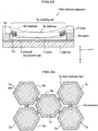
- a capacitor is formed by a bottom electrode 2 (which is an electrode on a substrate side and will be hereinafter also referred to also merely as an electrode 2) and a top electrode 3 (which is an electrode on an outer diaphragm layer 5b side and will be hereinafter also referred to merely as an electrode 3) which are provided respectively on a substrate 1 and on a flat outer diaphragm layer 5b with a cavity 4 therebetween.
- the direction where the ultrasonic transducer lOOp receives ultrasound (downward direction in Fig. 40 ) will be referred to as z direction
- the right direction in Fig. 40 will be referred to x direction
- the perpendicular downward direction with respect to the sheet of Fig. 40 will be referred to as y direction.
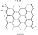
- a number of the above described transducers are disposed and arrayed, as shown in Fig. 43 , to be used.
- plural hexagonal ultrasonic transducers 100 are electrically connected by connection 13 arranged between ultrasonic transducers to form a single channel partitioned by shown dashed lines 20.
- Ultrasonic pulses are transmitted and received, utilizing ultrasonic transducers.
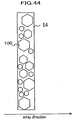
- the degree of freedom in controlling a device is advantageously increased, an example of which is that different frequencies can be selected, depending on the distance from an ultrasonic transducer to a subject. Therefore, a method is disclosed, in Patent Document 1, to achieve a broadband by simultaneously driving ultrasonic transducers 100, as shown in Fig. 44 , having respective diaphragms in different diameters, the ultrasonic transducers being connected by connections therebetween to serve as a single element 14.
- Patent Document 2 discloses a capacitive ultrasonic transducer reinforced by a stiffing layer at the central portion of a film.
- Patent Document 3 discloses an acoustic transducer with a structure, arranged above a cavity, having an insulating layer part and a top electrode which are disposed within the thickness dimension of a film.
- Non-patent Document 1 " A surface micromachined electrostatic ultrasonic air transducer", Proceedings of 1994 IEEE Ultrasonics Symposium, pp. 1241-1244
- JP 2005 110204 A discloses a capacitor microphone with microphone units using beams of varying configuration disposed on diaphragms allowing the microphone to cover a wide resonance frequency range.
- an ultrasonic probe configured with diaphragms in polygonal or circular shapes in different sizes packed in an area inevitably has gaps between ultrasonic transducers. These gaps make a problem of deteriorating the performance of the ultrasonic probe due to the following two causes.
- Reverberant sound may also be caused by the phenomenon that an ultrasound from a diaphragm passes through a portion not formed with a diaphragm, and this propagated ultrasound is reflected by the edge of an adjacent ultrasonic transducer, and finally returns to the original diaphragm.
- the upper limits of the sizes of respective ultrasonic transducers are defined by the disposition pitch for which diffraction of ultrasound and the like is taken into account, and the lower limits of the sizes are defined from a point of view of securing radiation impedance which achieves a required radiation efficiency. Therefore, the sizes of these ultrasonic transducers are selected usually from a narrow range in designing.
- Non-patent Document 1 since a semiconductor manufacturing technology is used for the above described conventional electrostatic transducer (described in Non-patent Document 1), masks corresponding to the planar shapes of diaphragms are used in a manufacturing process. There is a method of changing the frequency spectrum of a diaphragm, which changes the size (planar shape) of the diaphragm. However, it is necessary to design and manufacture a new mask for this method, which requires time and cost, causing a problem of decreasing the manufacturing efficiency.
- another method of changing the frequency spectrum of a diaphragm changes the thickness of the diaphragm.
- the thickness of the diaphragm which achieves a desired center frequency is substantially uniquely determined.
- the size and thickness of the diaphragm define the sensitivity and fractional bandwidth of this ultrasonic transducer. Consequently, there has been a problem that a desired frequency spectrum, namely, a combination of a center frequency and a fractional band width cannot be realized.
- an object of the present invention is to provide an ultrasonic transducer, ultrasonic probe, and ultrasonic imaging device having a simple structure and being capable of improving the performance of transmission and reception of ultrasound.
- the ultrasonic transducer of the present invention is defined in Claim 1. Further advantageous features are set out in the dependent claims.
- an ultrasonic probe which have a simple structure and are capable of improving the performance of transmission and reception of ultrasound are provided.
- an ultrasonic transducer a converter between electricity and ultrasound
- a transducer array a group of plural ultrasonic transducers in an array
- an ultrasonic imaging device will represent “an imaging device by the use of ultrasound provided with an ultrasonic probe, image former (means for forming an image from a signal obtained by an ultrasonic probe), display (means for displaying an image), controller, and the like”.
- Fig. 1 is a diagram showing an example of a structure of an ultrasonic imaging device using ultrasonic transducers in a first embodiment. Referring to Fig. 1 , the operation of the ultrasonic imaging device will be described.
- a transmission delay and weight selector 203 selects the values of a transmission delay time and a weight function for each channel to be supplied to a transmission beam-former 204. According to these values, the transmission beam-former 204 supplies an electro-acoustic conversion element 101 with transmission pulses through plural switches 205 for switching transmission/reception waves.
- an electro-acoustic conversion element 101 is also applied with a bias voltage by a bias voltage controller 202. As a result, the electro-acoustic conversion element 101 transmits ultrasound to a specimen, not shown here.
- a transmission/reception sequence controller 201 controls a reception beam-former 206 after a predetermined time has elapsed from the timing of transmission so as to start a reception mode.
- the predetermined time described above in a case of obtaining an image from a depth of a specimen deeper than 1 mm for example, is the turn around time for a sound to return a distance of 1 mm.
- the mode does not change to the reception mode immediately after transmission because the amplitude of the reception voltage is extremely smaller than the amplitude of the transmission voltage, being one hundredth to one thousandth.
- the reception beam-former 206 continuously controls the delay time and a weight function, corresponding to the arrival time of each reflected ultrasound, which is so-called a dynamic focus.
- Data after dynamic focus is converted into an image signal by image forming means including, for example, a filter 207, envelope detector 208, and scan converter 209, and then displayed on a display 210 as an ultrasonic tomographic image.
- a center frequency f c is a frequency with the highest electromechanical conversion efficiency (sensitivity) .
- a fractional bandwidth f h is, for example in a case of 3dB width, defined as a difference between two frequencies divided by the center frequency, wherein the sensitivity at these two frequencies is 3 dB lower than the sensitivity at the center frequency.
- a single ultrasonic transducer can be used for more various frequency bands, or ultrasonic pulses with a shorter time width can be formed, which achieves advantageous characteristics, such as obtaining a high distance resolution in a case of imaging by the use of ultrasonic beams.
- the center frequency f c of a diaphragm type ultrasonic transducer is substantially equal to the value of resonance frequency of the diaphragm, and is accordingly represented by following Expression (1), while the fractional bandwidth f h is represented by Expression (2), wherein the stiffness and the mass of the diaphragm are represented respectively by D and m.
- the stiffness and mass of an oscillation diaphragm are determined by the shape and dimensions of the oscillation diaphragm and the thickness thereof in a case of a solid material. Accordingly, in principle, by defining a proper shape and thickness of an oscillation diaphragm, a desired frequency spectrum can be obtained. However, only the two-degree-of-freedom of D and m for designing is not enough to optimize the three parameters of the center frequency, maximum value of sensitivity and fractional bandwidth.
- An ultrasonic probe for an ultrasonic imaging device for photographing common two-dimensional tomographic images performs fixed focusing by an acoustic lens in the direction (short axis direction) perpendicular to the tomographic plane, and performs electronic focusing of an ultrasonic beam at a desired position on the tomographic plane, having arrayed oscillators arranged in the direction (long axis direction) along the tomographic plane.
- ultrasonic transducers are arrayed ideally with a width of approximately a half of the wavelength at the center frequency of beams. For example, with a center frequency of 5 MHz, ultrasonic transducers are arrayed with a width of approximately 0.15 mm.
- the width along the short axis is preferably 7 to 8 mm.
- Patent Document 1 In the specification of United States Patent No. 5, 870, 351 (Patent Document 1), an example, as shown in Fig. 44 , is disclosed where a number of hexagonal shapes of diaphragms with different diameters are disposed in a single element which are electrically connected.
- Fig. 44 When circles or polygonal shapes with different diameters are packed in an area, there arises a problem that the packing efficiency drops.
- the pulse response of the element is greatly affected. This deterioration of pulse response will be described, referring to Fig. 45 . As shown in Fig.
- the total length of a path (arrow in the figure) on which an ultrasonic wave passes from one diaphragm through spaces where no diaphragm is formed, gets reflected by the surfaces of diaphragms adjacent to the one diaphragm, and returns to the one diaphragm is longer than in a case where hexagonal diaphragms with the same diameter are packed to form an array.
- Fig. 2 is a diagram of graphs showing a result of a simulation of a received ultrasonic pulse response by finite element method in a case of changing the distance between one diaphragm and adjacent diaphragms.
- a two dimensional model with diaphragms with a width of 60 ⁇ m and an unlimited length is employed.
- the material of the diaphragms is silicon nitride (SiN), and the thickness is 1.2 ⁇ m.
- Ultrasonic waves arriving from the front face of the array are sine waves with a center frequency of 10 MHz, and a cycle number of one periodic time.
- the horizontal axis represents time with an origin being the time when an ultrasonic pulse arriving from the front face of the array arrives at the surface of a diaphragm.
- the vertical axis represents the vertical velocity of the central portion of the diaphragm.
- the four graphs show the cases where the distance between adjacent diaphragms are 5 ⁇ m, 20 ⁇ m, 40 ⁇ m and 60 ⁇ m.
- the wider the distance between adjacent diaphragms the wider the pulse width.
- the diaphragm is deformed substantially the same as the waveform of an ultrasonic wave arriving from outside; the central portion of the diaphragm oscillates in a sine wave for one periodic time; thereafter (approximately 0.1 ⁇ sec later), the oscillation amplitude rapidly becomes small; the pulse width is narrow; and the frequency spectrum of the transmission function converting the ultrasonic wave to the deformation of the diaphragm is substantially flat.
- the wider the distance between the adjacent diaphragms the more the pulse waveform is extended.
- the pulse width is extended substantially 1.5 times compared with the case of the distance between adjacent diaphragms of 5 ⁇ m, showing that using an array in such conditions deteriorates the space resolution.
- Fig. 3 is a diagram of graphs showing waveforms of reception pulses in cases with the distance between adjacent diaphragms of 20 ⁇ m, 40 ⁇ m, and 60 ⁇ m, subtracted by a waveform of a reception pulse in a case of the distance between adjacent diaphragms of 5 ⁇ m.
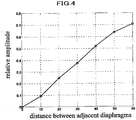
- the integrated values of the amplitudes of the reflected waves are represented by the vertical axis, and the distances between adjacent diaphragms are represented by the horizontal axis, in the graph in Fig. 4 .
- the vertical axis is normalized by the integrated value of the amplitude of the original reception waveform. It is shown that the value of the vertical axis becomes 0.1 or smaller where affects by a reflected wave can be almost neglected, when the distance between adjacent diaphragms is 10 ⁇ m or smaller.
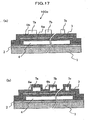
- Fig. 46(a) and 46(b) illustrate the mechanism in which an ultrasonic wave entering a substrate from a gap between diaphragms generates a noise.
- Fig. 46(a) is a schematic cross-sectional view of a diaphragm and the peripheral
- Fig. 46 (b) is a diagram showing the temporal change in a gain voltage signal.
- an ultrasonic pulse A having directly entered a diaphragm is first converted into an electrical signal, as shown as A in the graph with the horizontal axis of time and the vertical axis of echo voltage signal in Fig. 46(b) .
- an ultrasonic pulse B having arrived in a region of a gap between diaphragms, as shown by paths a, b and c in Fig. 46 (a) repeats multiple reflections in the substrate, passes through a limb portion of a diaphragm, and arrives at the diaphragm.
- the ultrasonic pulse having passed through the paths a, b and c is also converted into an electric signal by deforming the diaphragm, and appears as an electric signal with waveforms B, B' and B" as shown in Fig. 46(b) .
- an ultrasonic imaging device in a case, for example, of observing the inner structure of a blood vessel, in order to observe sites of which reflectance intensities differ from each other by 40 dB to 60 dB, such as the tissue site of the blood vessel and the lumen of the blood vessel, an image of the structure is created by compressing the brightness and with a wide dynamic range. Therefore, even if the echo of B and B' are imperceptible, when echo of delayed B and B' accompanies the reflectance signal A from the tissue site of the blood vessel, the echo is observed as an image inside the blood vessel, which does not allow distinction between a plaque in the blood vessel and a false image of B or the like.
- the amplitude of a reflectance signal B is necessary to be reduced to one thousandth, namely approximately -60 dB, compared with the amplitude of a reflectance signal A.
- the transmission efficiency of a sound through the gap drops and effect by a reverberant sound, such as B, does not become a problem.
- the shapes and structures of diaphragms are adopted which are suitable for making the resonance frequencies differ from each other to widen the fractional bandwidth, while minimizing the areas of gaps between diaphragms.
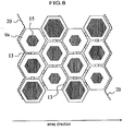
- Fig. 5 shows an example of an ultrasonic probe in the present embodiment, and is a top view showing a part of a semiconductor diaphragm type transducer array configuring the ultrasonic probe.
- Fig. 6 is a schematic diagram showing an oblique top view of one of the diaphragm type ultrasonic transducers in the array shown in Fig. 5 , the one being cut for viewing.
- Each diaphragm type ultrasonic transducer is, as shown in Fig. 6 , includes a bottom electrode 2 (the first electrode) formed on a substrate 1, an inner diaphragm layer 5a being formed on the bottom electrode 2 and having a cavity 4 therein, a top electrode 3 (the second electrode) provided on the inner diaphragm layer 5a, and an outer diaphragm layer 5b, which are disposed in this order, and a beam 7 connecting opposite apexes of the diaphragm, the beam being formed on the outer diaphragm layer 5b.
- the bottom electrode 2 and the top electrode 3 are facing each other through the inner diaphragm layer 5a having the cavity 4 therein, and configure a capacitor.
- a film in a homothetic shape of the diaphragm is formed to be continuous with the beam 7.
- both or either the inner diaphragm layer 5a or the outer diaphragm layer 5b may be described merely as “diaphragm” . Further, symbols of other elements may be omitted.
- a diaphragm type ultrasonic transducer applying a high DC bias improves the sensitivity of transmission and reception because more charges are accumulated. However, if an excessive DC bias is applied, a part of the diaphragm comes in contact with the opposite surface of the cavity 4.
- Such a contact causes charge emission into the diaphragm, and drifts the electro-acoustic conversion characteristics of the element.
- the contact starts at the gaps between the beams 7 and a portion adjacent to the center of the diaphragm.
- the diameter of the homothetic shape is preferably approximately 50% to 80% of the diameter of the entire diaphragm.
- the beams 7 have a structure having a smaller width compared with the length and a shape covering only a part of the diaphragm.
- the beams 7 effect the resonance frequency of the diaphragm type entire ultrasonic transducer, by having the hardness conditions described below. That is, the hardness of the beams 7 is made great enough compared with the hardness of the material of the diaphragm portion forming the upper wall of the cavity 4, or the thickness of the beams 7 is made great enough compared with the thickness of the diaphragm portion.
- the resonance frequency of the diaphragm type entire ultrasonic transducer can be controlled by the shape and material of the beam 7.
- the resonance frequency f b in the thickness direction is represented by the following Expression (3).
- E denotes Young's Module
- I denotes the cross-sectional moment
- m denotes the mass.
- Equation (3) is equivalent to Equation (4).
- Equation (4) is a proportional expression, coefficients are omitted.
- the resonance frequency f b is proportional to the square root of the width W.
- the beams 7 are in a rectangular solid shape with a width of W at the marginal portion, and are in a homothetic shape of the diaphragm, as shown in Figs. 5 and 6 , at the central portion of the diaphragm, assuming that the central portion of the diaphragm to be approximately a spindle with a mass of M, Expression (3) is described as Expression (5), and almost the same case as described above is applicable.
- Expression (3) is described as Expression (5), and almost the same case as described above is applicable.
- the resonance frequency of a diaphragm can be controlled by the width W of beams 7 in such a manner, then, by packing ultrasonic transducers having diaphragms with a constant diameter and beams 7 with different widths W provided on the front surfaces or back surfaces of the respective diaphragms, as shown in Fig. 5 , it is possible to configure a single ultrasonic transducer with diaphragm type plural ultrasonic transducers with different resonance frequencies, without gaps between the diaphragms.
- the boundary of an ultrasonic transducer that functions as a single element is shown by dashed lines 20.
- the bottom electrode 2 is common to the diaphragm type plural ultrasonic transducers configuring the single ultrasonic transducer, and the top electrodes of the diaphragm type plural ultrasonic transducers configuring the single ultrasonic transducer are electrically connected mutually by connections 13.
- a substrate 1 is made of silicon and a bottom electrode 2 with a thickness of approximately 500 nm and made of metal or polysilicon is formed on the silicon substrate.
- a bottom electrode 2 with a thickness of approximately 500 nm and made of metal or polysilicon is formed on the silicon substrate.
- an insulation film of silicon oxide or the like is formed with a thickness of approximately 50 nm on which a cavity 4 with a dimension in the thickness direction of approximately 200 nm is formed.
- An insulation film (the first diaphragm) 5 is formed with a thickness of approximately 100 nm to form the upper wall of the cavity 4, and a top electrode 3 is formed with a thickness of approximately 400 nm of metal such as aluminum on the insulation film 5.
- an outer diaphragm layer 5b with a thickness of approximately 200 nm of silicon nitride to cover the entire cavity 4, and further on the outer diaphragm layer 5b, formed is a film of silicon nitride with a thickness of approximately 1000 nm to form beams 7.
- the center frequency is 7.8 MHz and -6 dB fractional bandwidth is 120% (-6 dB fractional band is 3 to 12.5 MHz) with W 1 of 0.5 ⁇ m
- the center frequency is 10 MHz and -6 dB fractional bandwidth is 100% (-6 dB fractional band is 5 to 15 MHz) with W 2 of 4 ⁇ m
- the center frequency is 11.5 MHz and -6 dB fractional bandwidth is 96% (-6 dB fractional band is 6 to 17 MHz) with W 3 of 20 ⁇ m.
- -6 dB band becomes 3 to 17 MHz, that is, -6 dB fractional bandwidth becomes 140%.
- -6 dB fractional bandwidth is improved by 40 to 20 points.
- a film in a homothetic shape of the diaphragm in a polygonal shape is formed at the central portion of the diaphragm continuously with the beams 7.
- the same effect can be obtained of course.
- it is also possible to set different resonance frequencies of individual diaphragms by providing hard regions 15 in the respective central portions of the diaphragms and changing the sizes of the hard regions 15, without changing the size of the entire diaphragms.
- a structure in which beams 7 having different widths and connecting opposite apexes of diaphragms in a polygonal shape are formed on the front surfaces or back surfaces of diaphragms, as shown in Fig. 5 and Fig. 7 .
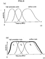
- Fig. 9(a) is an illustration on how to select frequencies for respective observation sites, in a case of using a conventional probe with a fractional bandwidth of approximately 60%.
- attenuation accompanying propagation of an ultrasound becomes greater substantially proportionally to the frequency. Therefore, in a case of observing with high penetration into a specimen, almost no signal returns due to attenuation.
- an optimum frequency is substantially automatically determined, wherein selected are frequencies of approximately 2 MHz for observation at a depth of 15 to 20 cm from a body surface (such as a liver), approximately 10 MHz for observation at a depth of several centimeters from the body surface (such as a thyroid), and higher for a case such as a probe in a blood vessel.
- the element width is necessary to be switchable. Switching of the element width is determined when an object site is selected.
- the element width is constant in a single imaging plane.
- the object site is relatively large and the element width is necessary to be changed even in a single screen depending on the place to set the object site.
- the object site is extending from a vicinity of the body surface to a deep portion and the element width is necessary to be switched accompanying the movement of the focus position while receiving ultrasound. For example, a case of switching the element width while receiving ultrasound will be described, referring to a device diagram.
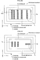
- An ultrasonic pulse in a wide band is applied from a transmission beam-former 204 in Fig. 1 through a switch 205 and sub-element cross point switch 17 to an ultrasonic probe configured with sub-elements 16, and the ultrasonic pulse is transmitted to a specimen not shown.
- the transmission beam-former 204 improving signal/noise ratio by widely transmitting ultrasonic pulses is more important than increasing the space resolution by narrowing the beam. Therefore, the number of sub-elements per channel is set small, and the total aperture is set narrow. Since ultrasounds scattered in a specimen return in order of nearness to the surface of the specimen, ultrasounds return in ascending order of the propagation distance in the specimen. In a conventional technology, ultrasounds returning from the specimen are received by reception beam-former 206 through the switch 205; the delay time and weight coefficient are adjusted between channels; and a tomographic image is displayed through an envelope detector and a scan converter.
- a sub-element cross point switch 17 between the sub-elements 16 and the switch 205 when ultrasounds from near-surface portions are received, sub-elements are bundled in the quantity corresponding to the upper end of the band having transmitted the ultrasounds, and when ultrasounds from deeper portions are received, sub-elements are bundled in the quantity corresponding to the lower end of the band having transmitted the ultrasounds.
- the time is continuous from when ultrasounds are received from the near-surface portions until when ultrasounds are received from deeper portions, and accordingly, switching of the quantity of sub-elements is necessary to be carried out continuously in terms of time.
- diaphragms in a hexagonal shape are connected criss-crossingly to form an ultrasonic transducer of a single electrical element.
- the element width can be changed corresponding to the mode.
- the mode is imaging conditions automatically determined by the depth of the object site.
- the photograhing conditions include the drive frequency, cut-off value of the frequency filter for reception, the number of transmission sine waves, temporal weight function, aperture weight function, and the like.
- the range of the depth of imaging is usually determined, and the degree of attenuation of propagation medium can be estimated. Accordingly, various conditions, such as an optimum frequency, are determined.
- an optimum frequency is determined.
- the object site often extends from a near portion to a far portion even if the object site is determined. Therefore, in some cases, plural modes are applied even for a single object site, and the modes are automatically switched depending on the depth generated by a reflected echo.
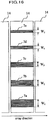
- Sub-elements are configured by a group of diaphragm type ultrasonic transducers of which top electrodes are permanently connected by conductors.
- the sub-element When a sub-element configures one element for beam forming, the sub-element serves as a unit of ultrasonic transducer bundled by a switchable switch.
- dashed lines 20 show the boundaries between sub-elements of ultrasonic transducers which are electrically connected.
- Fig. 10 four sub-elements 16a to 16d are shown which are electrically connected in a direction perpendicular to the array direction.
- an element width of 0.55 mm being 75% of a wavelength at 2 MHz can be achieved by 11 rows of diaphragms with a diameter of 50 ⁇ m, and the element width of 55 ⁇ m being 75% of a wavelength at 20 MHz can be achieved by one row of diaphragms with a diameter of 50 ⁇ m, which achieves an optimal element pitch for each mode in the range from 2 MHz to 20 MHz.
- an element width of 0.55 mm can be attained by simultaneously driving eleven bundled adjacent sub-elements as one element, and when driving an ultrasonic probe at 20 MHz, an element width of 55 ⁇ m can be attained by driving individual sub-elements independently.
- Fig. 11 is a diagram specifically illustrating how to change the number of sub-elements to be bundled and an effect of it.
- Fig. 11(a) shows the state where the focus of a transmission wave or reception wave is set to the nearest distance Fn.
- the total aperture width Wn Ws x N for a system with the number of channels N.
- Fig. 11b shows a state where the focus is set to a deeper distance Ff.
- F value in other words, focal length/ aperture width can be maintained to be substantially constant. Accordingly, compared with a case where the element width and the number of channels are constant, it is possible to inhibit generation of grating lobes (unnecessary emission) due to a too small F value at a near distance. Also, at a far distance, defocusing due to a too large F value can be inhibited.
- This sub-element cross point switch can be mounted in the ultrasonic imaging device.
- the number of cables 18 can be reduced to the necessity minimum by providing a sub-element cross point switch 17 on the sub-elements 16 side, rather than arranging cables 18 connecting the connector 19 in connection with the ultrasonic imaging device and the ultrasonic transducers.
- Fig. 13(a) is a schematic plan view showing an example of an ultrasonic probe using diaphragm type ultrasonic transducers having a rectangular diaphragm.
- Fig. 14 is a cross-sectional view along the array direction. As shown in Fig. 14 , with a structure where the widths of the cavity portions are different from each other, plural diaphragms having different resonance frequencies can be provided in an electrically connected single element.
- plural diaphragms each of which is an element configuring the respective diaphragm type ultrasonic transducer, are disposed in such a manner that the longer sides of the diaphragms are in the same direction as the longer sides of a single electrically connected element 14, namely, in the direction perpendicular to the array direction of the transducer array.
- a top electrode substantially in the same shape as the diaphragm and a cavity are provided, and a common (shared) bottom electrode arranged below the cavity and the top electrode configure a capacitor.
- each ultrasonic transducer provided with a rectangular diaphragm has a resonance frequency defined by the length of shorter sides of the diaphragm.
- a single ultrasonic transducer can be obtained in which plural diaphragms, which are disposed without a gap therebetween and have different center frequencies, are simultaneously driven electrically, by selecting a combination of the lengths of the shorter sides of diaphragms such as to divide the shorter side of the electrically connected single element 14 into plural parts.
- the center frequency is 7.8 MHz and the -6 dB fractional bandwidth is 120% (-6 dB fractional band is 3 to 12.5 MHz) for W 1 of 60 ⁇ m
- the center frequency is 10 MHz and the -6 dB fractional bandwidth is 100% (-6 dB fractional band is 5 to 15 MHz) for W 2 of 50 ⁇ m
- the center frequency is 11.5 MHz and the -6 dB fractional bandwidth is 100% (-6 dB fractional band is 6 to 17 MHz) for W 3 of 40 ⁇ m.
- -6 dB band becomes 1 to 15 MHz, that is, -6 dB fractional bandwidth becomes 140%. Since -6 dB fractional bandwidth of a conventional known diaphragm structure is approximately 100 to 120%, -6 dB fractional bandwidth is improved by 20 to 40 points.
- Fig. 13(b) is a schematic plan view showing another example of an ultrasonic probe using a diaphragm type transducer array, the diaphragms being rectangular.
- this ultrasound probe plural diaphragms each of which is an element configuring the respective ultrasonic transducer are disposed in such a manner that the longer sides of them are in the same direction as the shorter sides of an electrically single element 14, in other words, in the same direction as the array direction of the transducer array.
- a top electrode substantially in the same shape as the diaphragm and a cavity are provided, and a common bottom electrode arranged below the cavity and the top electrode configure a capacitor.
- Fig. 15 setting such as to allow free changing of the element width along the array long axis direction, depending on the mode, is advantageous in a viewpoint of fully utilizing the wide band characteristics of an ultrasonic probe.
- plural ultrasonic transducers are connected only along the direction perpendicular to the array direction and a number of sib-elements are formed, and the element width along the array long axis is changed by changing bundling of sub-elements.
- Fig. 15 plural ultrasonic transducers are connected only along the direction perpendicular to the array direction and a number of sib-elements are formed, and the element width along the array long axis is changed by changing bundling of sub-elements.
- Fig. 16 is a schematic plan view of an ultrasonic transducer in a second embodiment.
- Fig. 17(a) is a schematic cross-sectional view of it.
- an ultrasonic transducer 100q having a wide band can be realized.
- an element driven by a single electric signal in other words, a single electric element, is configured with a single diaphragm, wherein the bandwidth as the entire diaphragm is widened by aligning plural beams 7 having different center frequencies on the single diaphragm.
- plural rectangular beams 7a to 7e are formed crossing the short side direction of diaphragms, on a rectangular outer diaphragm layer 5b configuring a single ultrasonic transducer.
- the widths of the shorter sides of the beams 7a, 7b, 7c, 7d, and 7e are respectively W1, W2, W3, W4and W5, and the widths W1to W5are different from each other.
- the relationship between the diaphragm and the beams 7 is the same as the relationship between W1, W2 and W3, in Fig. 5 , and the resonance frequencies.
- beams with different widths may be embedded inside the outer diaphragm layer 5b.
- beams 7 having respective center frequencies are disposed with periodicity as little as possible, the same as described above, with care not to form grating lobes (unnecessary emission).
- a 1.5-dimensional array has a structure for which an array is arranged also along the direction (long axis) for scanning the position or direction of an ultrasonic beam, in other words, along the direction (short axis) perpendicular to the imaging plane, and thereby focusing along the short axis can be made variable.
- Fig. 18 is a vertical cross-sectional view showing an ultrasonic transducer 100 in the third embodiment.
- Fig. 19 is a plan view showing the ultrasonic transducer 100.
- the direction where the ultrasonic transducer 100 receives ultrasound namely, the downward direction in Fig. 18 and the perpendicular downward direction with respect to the sheet of Fig. 19 will be referred to as z direction.
- z direction the direction where the ultrasonic transducer 100 receives ultrasound
- x direction the direction where the ultrasonic transducer 100 receives ultrasound
- y direction the perpendicular downward direction with respect to Fig. 18 , which is also the upward direction in Fig. 19
- this ultrasonic transducer 100 is an electrostatic diaphragm transducer including a flat plate shaped substrate 1 of insulating material, such as a monocrystalline silicon, or semiconductor material, an electrode 2 disposed on the top of the substrate 1 and formed of a conductive material, such as aluminum, in a thin film shape, a diaphragm 5 disposed on the top surface of the electrode 2 and formed in a thin plate shape, and one or plural beams 7 formed on the top of the diaphragm 5.
- insulating material such as a monocrystalline silicon, or semiconductor material
- an electrode 2 disposed on the top of the substrate 1 and formed of a conductive material, such as aluminum, in a thin film shape
- a diaphragm 5 disposed on the top surface of the electrode 2 and formed in a thin plate shape
- one or plural beams 7 formed on the top of the diaphragm 5 formed on the top of the diaphragm 5.
- the surface which is provided with the diaphragm 5 and transmits ultrasound will be referred to as the top surface and the surface on the side of the substrate 1 will be referred to as the bottom surface.
- the diaphragm 5 has a cavity 4 therein, and the portion covering the top of the cavity 4 forms an oscillating part 5c for generating ultrasound by oscillation.
- the diaphragm 5 includes the cavity 4 making the distance between the oscillating part 5c of the diaphragm 5 and the electrode 2 on the substrate 1 side, and provided with an inner diaphragm layer 5b which causes insulation so that the electrode 2 on the substrate 1 side and an electrode 3 (described later) on the diaphragm 5 side are not electrically conducted with each other even when the oscillating part 5c is deformed excessively, an outer diaphragm 5b formed such as to cover the top surface of the inner diaphragm 5a, and the electrode 3 disposed on the diaphragm 5 side and formed of the same material as the electrode 2 and in a thin film shape between the inner diaphragm layer 5a and the outer diaphragm layer 5b.
- diaphragms 5 and beams 7 are those described in United States Patent No. 6,359, 367 , for example.
- Examples are silicon, sapphire, any sort of glass material, polymers (such as polyimide), polysilicon, silicon nitride, silicon oxynitride, thin film metals (such as aluminum alloys, copper alloys and tungsten), spin-on-glasses (SOGs), implantable or diffused dopants and grown films such as silicon oxides and silicon nitrides.
- the distance between the oscillating part 5c of the diaphragm 5 and the substrate 1, that is the thickness of the cavity 4 (dimension in z direction) is maintained mainly by the stiffness in the upper and lower direction (z direction) of both or either the inner diaphragm layer 5a or the outer diaphragm layer 5b. Further, this stiffness is reinforced in a predetermined direction by the beams 7.
- a significant feature of an ultrasonic transducer 100 in the present embodiment is that beams 7 are arranged on a diaphragm 5, and the stiffness of the diaphragm 5 is adjusted.
- a desired combination of a resonance frequency f b and a fractional bandwidth f h can be achieved by appropriately setting the combination of the thickness (the length along z direction) of the diaphragm 5 and the thickness (the length in z direction) of the beams 7.
- this ultrasonic transducer 100 acts as a variable capacity capacitor having an electrode 2 on the substrate 1 side and an electrode 3 on the diaphragm 5 side, the both electrodes serving as polar plates, with the cavity 4 disposed therebetween and functioning as a dielectric.
- the diaphragm 5 when a force is applied to the diaphragm 5, the diaphragm is displaced and thereby the distance between the electrode 2 and electrode 3 changes, thus the capacitance of the capacitor changes.
- a difference in potential is applied to the electrode 2 and electrode 3
- respective opposite charges are accumulated in them to cause forces acting on each other, and thus the diaphragm 5 is displaced.
- the ultrasonic transducer 100 is an electro-acoustic conversion element that converts a high frequency electric signal, which has been input, into an ultrasonic signal and emits the ultrasonic signal to a medium, such as water or a living organism, and then converts an ultrasonic signal being input from the medium into a high frequency electric signal and outputs the high frequency electric signal.
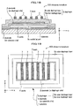
- Fig. 20 is a perspective view showing a transducer array 1000.
- This transducer array 1000 serves as the ultrasound transmission/reception surface of an ultrasonic probe (not shown), and is formed with a number of ultrasonic transducers 100, described above, on a substrate 1, the ultrasonic transducer 100 being connected by connections 13 by the unit of a predetermined number.
- the number of the ultrasonic transducers 100 is not limited to the number shown, and ultrasonic transducers 100 in an even greater number may be integrated on a larger substrate 1, depending on a semiconductor manufacturing technology.
- ultrasonic transducers 100 or ultrasonic transducers 100 bundled by a unit of predetermined number are connected through a transmission and reception switch to a transmission beam-former and a reception beam-former (both not shown) of an ultrasonic imaging device provided with this ultrasonic probe, and acts as a phased array to be utilized for transmission and reception of ultrasounds.
- the shown array of the ultrasonic transducer 100 is an example, and other forms of arrays may be arranged, including a honeycomb shape and grid shape. Further, the array surface may be either a flat surface or curved surface, and the outline of the surface may be formed in a circle shape, polygonal shape, or the like. Or, the ultrasonic transducers 100 may be disposed on a line or a curve.
- This ultrasonic probe is provided with a transducer array 1000 formed, for example, in an array shape having a plurality of groups of ultrasonic transducers 100 arrayed on a line, or formed in a convex type having a plurality of ultrasonic transducers 100 arrayed in a fan shape. Further, on the medium (specimen) side of the ultrasonic transducers 100 of this ultrasonic probe, there are arranged an acoustic lens for convergence of ultrasonic beams, and an acoustic matching layer for matching the acoustic impedance between the ultrasonic transducers 100 and the medium (specimen) . Further, on the back side (reverse side with respect to the medium side), a packing member for absorbing propagation of ultrasonic waves is arranged.
- Fig. 21 is a diagram of a graph showing an example of frequency versus gain response of an ultrasonic transducer 100.
- the horizontal axis represents frequency f
- the vertical axis represents sensitivity G (Gain) indicating electro-mechanical conversion efficiency.
- frequency f at which the sensitivity G is the highest is defined as peak frequency f p
- the range where sensitivity G is not smaller than -3 [dB] from the highest value is defined as the frequency bandwidth f w .
- the frequency at the center of frequency bandwidth f w is defined as center frequency f c , and the value of frequency bandwidth f w divided by center frequency f c (in other words, the value of frequency bandwidth f w normalized by center frequency f c ) is defined as fractional bandwidth f h (not shown).
- Gain G means the efficiency of mutual conversion between electric energy and mechanical energy, such as mechanical energy of a sound wave. Accordingly, in view of increasing the transmission efficiency and detecting faint sound wave signals, gain G of the ultrasonic transducers 100 is desired to be high.
- the fractional bandwidth f h is another one of the significant characteristics of the ultrasonic transducers 100 .
- the greater the fractional bandwidth f h the wider the usable frequency range, and thus a single ultrasonic transducer 100 can be used for various purposes, which is an advantage of the ultrasonic transducer 100.
- the fractional band width f h is greater, ultrasonic pulses with narrower pulse widths (in other words, the occupied frequency band width is wider) can be formed, which is an advantage achieving high distance resolution in ultrasonic imaging.
- an ultrasonic transducer 100 is a diaphragm type
- the center frequency f c and the resonance frequency f b are substantially the same.
- the resonance frequency fb, stiffness D and mass m of a diaphragm 5 have relationship in Expression (1).
- Fractional band width f h has a relationship in Expression (2).
- the stiffness D and mass m of a diaphragm 5 are defined by the planar shape and thickness thereof when the material is determined in advance. Accordingly, if both the planar shape and the thickness of the diaphragm 5 can be properly set, a desired frequency spectrum (combination of the center frequency f c ( ⁇ resonance frequency f b ) and the fractional band width f h ) can me obtained.
- Fig. 22 is a schematic diagram showing a bending state of a beam 7.
- the beam 7 is in a rectangular solid shape with a width of w, length of v and thickness of t when no force is applied.
- the stiffness D in the thickness direction (oscillation direction of the diaphragm 5: z direction) of the beam 7 has the following relation in Expression (6), wherein the mass of the beam 7 is represented by m, and the Young's Module is represented by E. D ⁇ Ew t v 3
- the resonance frequency f b in the thickness direction t (z direction; oscillation direction of the diaphragm 5) of the beam 7 has the relationship of the following Expression (8).
- f b 2 ⁇ D m Et 2 ⁇ v 4
- the resonance frequency f b of the beam 7 is proportional to the thickness t.
- the thickness t is uniquely determined, when the planar shape (width w and length v) is determined in advance. Further, if the material and respective dimensions of the beam 7 are determined, then the mass m is also determined, and thereby the fractional band width f h is also uniquely determined. Still further, this description on the beam 7 is also true in the case of parts which can be assumed to be a rectangular homogeneous solid shape, for example, the oscillating part 5c (the flat shaped portion excluding the beams 7) of the diaphragm 5.
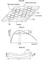
- Fig. 23 is a perspective view schematically showing an oscillating body 6a in accordance with the invention, and an oscillating body 6b in a comparative example.
- the oscillating body 6a in accordance by the invention follows the oscillating part 5c of the diaphragm 5 in the third embodiment, and is provided with a base plate 20a in a flat plate form and a single beam 7d on the base plate 20a.
- the thickness of the base plate 20a is t 1
- the thickness of the beam 7d is t 2 .
- the oscillating body 6b of the comparative example has a shape of the above described oscillating body 6a without the beam 7, and formed of a base plate 20b in a flat plate form.
- the thickness of the base plate 20b is t 0 .
- the length (dimension in y direction) of the base plate 20a and beam 7d of the oscillating body 6a and the length of the base plate 20b of the oscillating body 6b are both v.
- the both widths (dimension in x direction) of the base plate 20a and the base plate 20b are w 1
- the width (dimension in x direction) of the beam 7d is w 2 .
- the materials of the base plate 20a, base plate 20b, and beam 7d are all the same.
- Fig. 24 is a diagram of graphs showing a result of calculation of resonance frequencies f b and fractional bandwidths f h in a case where the width w 2 of the beam 7d of an oscillating body 6a in accordance with the invention is set to 20 percent of the width w 1 of a base plate 20a.
- the horizontal axis indicates the thickness ratio t 2 /t 0 of a beam, namely, the value of the thickness t 2 of the beam 7d of the oscillating body 6a normalized by the thickness t 0 of the base plate 20b of an oscillating body 6b.
- the vertical axis indicates the thickness ratio t 1 /t 0 , namely, the thickness t 1 of the base plate 20a of the oscillating body 6a normalized likewise by the thickness t 0 of the base plate 20b of the oscillating body 6b.
- Each solid graph represents the value of the resonance frequency f b of oscillating bodies 6a in accordance with the invention normalized by the resonance frequency f b of an oscillating body 6b of a comparative example.
- the numeral given to each solid graph indicates the value of a normalized resonance frequency f b , wherein the values of normalized resonance frequencies f b are all the same at arbitrary positions on a same solid graph.
- Each dashed graph represents the fractional bandwidth f h of oscillating bodies 6a in accordance with the invention normalized by the fractional bandwidth f b of the oscillating body 6b of the comparative example.
- the numeral given to each dashed graph indicates the value of a normalized fractional bandwidth f h , wherein the values of normalized fractional bandwidths f h are all the same at arbitrary positions on a same dashed line.
- this oscillating body 6a is equivalent to a base plate 20b with a thickness of t 0 of a comparative example. That is, the thickness ratio t 1 /t 0 of the base plate 20a of this oscillating body 6a is set to 1.0, and the thickness ratio t 2 /t 0 of the beam 7d is set to 0.0.
- a combination of a thickness ratio t 1 /t 0 and a thickness ratio t 2 /t 0 is selected such that the value of the normalized resonance frequency f b is 1.0 (moving on a solid graph given with "1.0"), and thus the thickness t 1 of a base plate 20a and the thickness t 2 of a beam 7d can be obtained.
- a combination, which achieves the desired normalized value of a fractional bandwidth f h , of a thickness ratio t 1 /t 0 and a thickness ratio t 2 /t 0 is selected with the value of a normalized resonance frequency f b be 2.0 (moving on the solid graph given with "2.0" and finding the intersection point between this solid graph and a dashed graph given with the desired normalized value of a fractional bandwidth f h ), and thus the thickness t 1 of a base plate 20a and the thickness t 2 of a beam 7d can be obtained.
- an oscillating body 6a has a structure provided with a beam 7d on a base plate 20a, by properly setting the respective thicknesses (dimension in z direction) of these elements (the base plate 20a and the beam 7d), a desired frequency spectrum (a combination of a resonance frequency f b and a fractional bandwidth f h ) can be realized, even without changing the planar shape of these elements.
- Fig. 25 is a diagram of graphs showing a result of calculation of resonance frequencies f b and fractional bandwidths f h in a case where the width w 2 of the beam 7d of an oscillating body 6a in accordance with the invention is set to 80 percent of the width w 1 of a base plate 20a.
- Comparison of Fig. 24 and Fig. 25 proves that, if the ratio of the width w 2 of the beam 7d of an oscillating body 6a to the width w 1 of a base plate 20a is different from that in another case while the thickness t 2 of the beam 7d and the thickness t 1 of the base plate 20a are changed in the same way as in the other case, the frequency spectrum changes differently from the other case.
- the width w 2 of the beam 7d is increased having the width w 1 of the base plate 20a be constant, the planar shape of the beam 7d and the planar shape of the base plate 20a become closer to each other. Accordingly, if the resonance frequency f b is maintained constant, the adjustable range of the fractional bandwidth f h achieved by selecting a combination of the thickness t 1 of the base plate 20a and the thickness t 2 of the beam 7d becomes narrower.
- the width w2 of the beam 7d is made as small as possible compared with the width w1 of a base plate 20a in a range allowed by manufacturability.
- the material of the base plate 20a and the material of a beam 7d are the same, however, the same effect can be achieved also using different materials.
- Fig. 26 is a schematic perspective view showing a beam 7d of a modified example.
- This beam 7b is configured with a beam part 7ba with a width of w 2 , the beam part 7ba being a part of the beam 7b, and a beam part 7bb with a different width of w 22 , the beam part 7bb being another part of the beam 7b, wherein the beam parts 7ba and 7bb are joined with each other with respect to the thickness direction (z direction) with the same long axis direction.
- the thickness t 21 of the beam part 7ba and the thickness t 22 of the beam part 7bb can be selected independently.
- the fractional bandwidth f h can be continuously changed by changing the combination of the thickness t 21 of the beam part 7ba and the thickness t 22 of the beam part 7bb.
- Fig. 27 is a perspective view showing the shapes of a beam 7c1, 7c2 and 7c3 of other modified examples.
- the beam 7c1 having a cross-section in a triangle shape may be employed.
- the beam 7c2 having a cross-section in a trapezoidal shape may be employed.
- the beam 7c3 of which width changes along the long axis direction may be employed.
- the beam may have a rectangular solid shape, in other words, a shape with rectangular cross-sections in the short and long axis directions, or any other shape as long as the thickness (dimension along the oscillation direction of the diaphragm 5, namely, z direction) can be controlled during a manufacturing process.
- the beam may have a cross-section in a polygonal shape, such as a triangular, rectangular, trapezoidal or another quadrilateral shape, or a cross-section, such as a circular, ellipsoidal shape or the like, or a cross-section which changes along a certain direction.
- Ultrasonic transducers 100b to 1001 in the later described fourth to fourteenth embodiments can also be used in the ultrasonic probe described above.
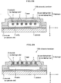
- Fig. 28 is a vertical cross-sectional view showing an ultrasonic transducer 100b in a fourth embodiment.
- This ultrasonic transducer 100b has a structure having beams 7 inside a cavity 4 of a diaphragm 5 (inner diaphragm layer 5a). That is, in the present embodiment, the beams 7 are disposed adjacent to an electrode 3 on the surface of the diaphragm 5 and on the side facing an electrode 2 on the substrate 1 side.
- This ultrasonic transducer 100b has the same effects as in the third embodiment, and allows the surfaces of the diaphragm 5 to be flat.
- Fig. 29 is a vertical cross-sectional view showing an ultrasonic transducer 100c in a fifth embodiment.
- This ultrasonic transducer 100c has a structure having beams 7 implanted in the substrate of a diaphragm 5 (more specifically, an outer diaphragm layer 5b). These beams 7 are formed of a material having a higher stiffness (the Young's Module) than that of the diaphragm 5 or a material having a lower stiffness than that of the diaphragm 5. Or, the beams 7 may be formed by cavities with vacuum therein or with air or another kind of gas charged therein.
- the direction and the amplitude of the stiffness of the diaphragm 5 can be adjusted as desired to change the stiffness, without changing the shape or thickness of the diaphragm 5. Further, the electro-acoustic efficiency can be increased by narrowing the distance between the electrode 2 and electrode 3.
- the beams 7 may be formed directly inside the inner diaphragm layer 5a or the outer diaphragm layer 5b, or may be formed by arranging recessions on the surface of the inner diaphragm layer 5a or the outer diaphragm layer 5b and joining the inner diaphragm layer 5a and the outer diaphragm layer 5b to seal these recessions.
- Fig. 30 is a vertical cross-sectional view showing an ultrasonic transducer 100d in a sixth embodiment.
- This ultrasonic transducer 100d has a structure having a beam 7z instead of the above described electrode 3 on the diaphragm side and beams 7.
- This beam 7z is formed, for example, of the same material as the above described electrode 3 on the diaphragm 5 side, or of another conductive material, and includes an electrode layer part 7zb in the same shape as the above described electrode 3 on the diaphragm 5 side, the electrode layer part 7zb being a part of the beam 7z, and beam parts 7za having a shape elongated along shown y direction and increasing the stiffness of the diaphragm 5 in y direction, each beam part 7za also being a part of the beam 7z.
- the beam parts 7za may be disposed in a grid pattern for example, without being limited to a single direction.
- the manufacturing process can be simplified and the structure can be hardened.
- this ultrasonic transducer 100d may have a structure which secures the most of the stiffness of the diaphragm 5 by the beam 7z serving also as an electrode and either the inner diaphragm layer 5a or the outer diaphragm layer 5b. Accordingly, either the inner diaphragm layer 5a or the outer diaphragm layer 5b is not required to take the role of securing the stiffness, and can be thinned or omitted. If the beam 7z secures most of the stiffness, the inner diaphragm 5a is unnecessary in principle. This allows narrowing the distance between the electrode 2 and the electrode 3 and improving the electro-acoustic conversion efficiency.
- the outer diaphragm layer 5b may have a thickness enough for protection or insulation.
- the manufacturing process can be simplified, and the distance between the electro-acoustic conversion section, configured by the beam 7z and the electrode 2 on the substrate 1 side, and a measured medium (not shown) can be shortened, which improves the sensitivity.
- Fig. 31 is a vertical cross-sectional view showing an ultrasonic transducer 100e in a seventh embodiment.
- this ultrasonic transducer 100e has a structure having a beam 7n formed of a material with a lower stiffness than that of a diaphragm 5 or formed as a cavity, adjacent to the portion where the diaphragm 5 supports itself on the electrode 2 on the substrate 1 side.
- this portion is a ring shaped potion inside the diaphragm 5 and is located above the marginal portion of the cavity 4, and is also a portion enclosing the oscillating part 5c of the diaphragm 5.
- the beam 7n lowers the stiffness of the marginal portion of the oscillating part 5c of the diaphragm 5, and thereby the stiffness of the entire oscillating part 5c improves relatively.
- Fig. 32 is a vertical cross-sectional view schematically showing the movement of the ultrasonic transducer 100e in the seventh embodiment.
- this ultrasonic transducer 100e has a structure where a support 5d holds the diaphragm 5n (shown by the solid curves) on the electrode 2 on the surface of the substrate 1.
- a diaphragm 5m in a case where the beam 7n is not provided is shown by the dashed curves.
- the diaphragm 5 when the diaphragm 5 oscillates upon transmission and reception of ultrasound, the diaphragm 5 is deformed greatly in the vicinity of the beam 7n, however, the entire oscillating part 5c of the diaphragm 5 (shown as diaphragm 5n) is uniformly displaced overall while a satisfactory flatness thereof is maintained. Therefore, the average displacement amount of the diaphragm 5 can be made large even without changing the maximum displacement amount, and also, it is possible to reduce the thickness (the length in z direction) of the cavity 4 and the distance between the electrode 2 and the electrode 3. In such a manner, the electro-acoustic conversion efficiency can be improved, and a high sensitivity and high output can be realized.
- Fig. 33 is a plan view of an outer diaphragm layer 5p in an eighth embodiment.
- An ultrasonic transducer 100f (not shown) in the eighth embodiment has a structure having an outer diaphragm layer 5p instead of the above described outer diaphragm layer 5b.
- This outer diaphragm layer 5p is provided with a number of beams 7p in a hole (or hollow) shape at the marginal portion of a planar shape. Similarly to the above described beam 7n, these many beams 7p lower the stiffness of the marginal portion of the outer diaphragm layer 5p and relatively improve the stiffness of the planar portion enclosed by the beams 7p.
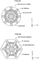
- Fig. 34 is a plan view of an ultrasonic transducer 100g in a ninth embodiment.
- This ultrasonic transducer 100g includes a circular diaphragm 5g, radial beams 7gr disposed radially on the top surface of the diaphragm 5g, and an annular beam 7gc disposed likewise.
- the diaphragm 5g may be in an ellipse shape.
- Fig. 35 is a plan view of an ultrasonic transducer 100h in a tenth embodiment.
- This ultrasonic transducer 100h includes a diaphragm 5h in a hexagonal shape, radial beams 7hr disposed radially on the top surface of the diaphragm 5h, and a cell shaped beam 7hc disposed along the inner margin of the diaphragm 5h likewise.
- the hexagonal shape is an example, and the shape of the diaphragm 5h may be a triangle, pentagon, heptagon, or another polygon.
- the above described radial beams 7gr are provided in a quantity of four (in eight directions from the center) in the ninth embodiment, and the above described radial beams 7hr are provided in a quantity of three (in six directions from the center) in the tenth embodiment.
- a suitable number of such beams may be provided, depending on the shapes of the diaphragms 5g and 5h, desired frequency spectrum and the like.
- the annular beam 7gc in the ninth embodiment and the cell shaped beam 7hc in the tenth embodiment are provided respectively in a single quantity, as examples.
- a suitable number of such beams may be provided, concentrically for example, depending on the shapes of the diaphragms 5g and 5h, desired frequency spectrum and the like.
- Fig. 36 is a plan view of an ultrasonic transducer 100i in an eleventh embodiment.
- This ultrasonic transducer 100i has a structure having plural beams 7 which are elongated in y direction and disposed at uneven intervals.
- the distribution of stiffness of the oscillating part 5c of a diaphragm 5 can be partially adjusted and an oscillation mode can be desirably inhibited or excited, by suitably setting the pitches of disposing the plural beams 7.
- Fig. 37 is a plan view of an ultrasonic transducer 100j, in a twelfth embodiment, for which the long axis directions of beams 7 are set to different directions.
- This ultrasonic transducer 100j has a structure having a beam 7x which is elongated in x direction and shorter in the long axis direction thereof than the length in x direction of an oscillating part 5c of a diaphragm 5, beams 7y which are elongated in y direction and shorter in the long axis direction thereof than the length in y direction of the oscillating part 5c of the diaphragm 5, the beams 7x and 7y being arranged on an outer diaphragm layer 5b.
- the beam 7x and 7y having different long axis directions may be disposed in mixture at different positions on the same diaphragm 5. Further, the beams 7x and 7y may have lengths shorter than the planar dimensions of the oscillating part 5c, depending on the purpose. Still further, the dimensions of the beams 7x and 7y may be different from each other.
- an oscillation mode/modes can be desirably inhibited or excited for each part of the oscillating part 5c, by suitably setting the positions, pitches, quantity of the beams 7y and 7x.
- Fig. 38 is a vertical cross-sectional view of an ultrasonic transducer 100k in a thirteenth embodiment.
- This ultrasonic transducer 100k has a structure having beams 7i, 7j and 7k which are elongated in y direction, have different cross-sections perpendicular to the long axis, and are disposed in mixture on a diaphragm 5.
- the beams 7i having the largest cross-section are disposed adjacent to the center of the diaphragm 5, the beams 7j having a smaller cross-section than the beams 7i are disposed outside the beams 7i, and the beams 7k having a smaller cross-section than the beams 7j are disposed outside the beams 7j.
- the stiffness of the portion in the vicinity of the center of the diaphragm 5 is greatly reinforced while the stiffness is less reinforced toward the marginal portion of the diaphragm 5. This disposition is an example and the order of disposing the beams 7i, 7j and 7k may be changed.
- the distribution of stiffness of the diaphragm 5 can be adjusted, and thereby, desired oscillation modes and resonance frequencies f b for the respective oscillation modes can be obtained.
- Fig. 39 is a plan view of an ultrasonic transducer 1001, in a fourteenth embodiment, provided with beams 7 of which long axes intersect with each other.
- This ultrasonic transducer 1001 has a structure having a beam 7q elongated in x direction (horizontal direction in the figure) and beams 7r elongated in y direction (vertical direction in the figure) on the top surface of an outer diaphragm layer 5b.
- the stiffness of the diaphragm 5 with respect to x direction can be changed by the horizontally elongated beam 7q
- the stiffness of the diaphragm 5 with respect to y direction can be changed by the vertically elongated beams 7r. Accordingly, even when the planar shape and dimensions of the oscillating part 5c of the diaphragm 5 are predetermined, it is possible to independently and arbitrarily set the resonance frequency f bx of an oscillation mode in x direction and the resonance frequency f by of an oscillation mode in y direction.
- the planar shape of the oscillating part 5c of the diaphragm 5 is substantially a square shape.
- the stiffness of this oscillating part 5c is reinforced by the single beam 7q elongated in x direction and the three beams 7r elongated in y direction.
- the oscillating part 5c of the diaphragm 5 has a small stiffness in x direction and a large stiffness in y direction despite the substantially square shape thereof.
- the beam 7q and each beam 7r may be joined with each other, or may intersect with each other in stories with respect to z direction (perpendicular direction to the sheet of the figure).
- the ultrasonic transducers 100, 100b to 1001 in the respective embodiments the following effects can be obtained, for example.
- Fig. 40 is a vertical cross-sectional view of an ultrasonic transducer lOOp of a Comparative Example.
- This ultrasonic transducer lOOp has the same structure as the ultrasonic transducer 100 (refer to Fig. 18 ) in the third embodiment except that no beam 7 is arranged.
- Fig. 41 is a diagram of a graph showing the frequency versus gain response of a diaphragm 5 in a rectangular planar shape with a ratio of longitudinal length to lateral length of 1:2.
- a notch (an area where gain G rapidly drops) appears near 0.8 MHz on the graph. Accordingly, there is a problem that the value of the frequency versus gain response of the diaphragm 5 is not flat. This notch is generated by the bonding between the lateral oscillation mode and the longitudinal oscillation mode. Therefore, it is understood that one of the oscillation modes can be inhibited and thereby notch is restricted by changing the longitudinal and/or lateral stiffness.
- the inventors produced design examples of the ultrasonic transducer 100 (refer to Fig. 18 ) in the third embodiment and the ultrasonic transducer lOOp of the comparative example, as described later. Design values were input in details to a computer, highly accurate numerical simulation was carried out regarding characteristic in water, and a result was compared with the calculation result described above (refer to Fig. 24 ).
- the substrate 1 is formed of silicon
- the diaphragm 5 is formed of silicon nitride
- the electrodes 2 and 3 are formed of aluminum.
- the vertical dimension (up-and-down direction, namely y direction, in Fig. 19 ) of the diaphragm 5 was set to 40 ⁇ m, and the length in the direction perpendicular to this direction on the same plate surface (left-right direction, namely x direction, in Fig. 19 ) was set approximately to 400 ⁇ m. These dimensions were set such as to make the vertical length/horizontal length ratio small enough, considering prevention of unnecessary oscillation modes from being excited. Further, the total thickness of the electrode 2 on the substrate 1 side and the substrate 1 is large enough for the displacement to be neglected substantially.
- the beams 7 of the ultrasonic transducer 100 are formed of the same material as the diaphragm 5.
- the width w of the beams 7 was set to 20 percent of the pitch between the beams 7.
- the resonance frequency f b of the diaphragm 5 in the third embodiment be the same as that of the diaphragm 5 in the comparative example and make the fractional bandwidth f h of the diaphragm 5 in the third embodiment is 1.5 times as wide as that in the comparative example, and based on the calculation result (refer to Fig.
- the diaphragm 5 of the ultrasonic transducer 100 was made 0.54 times as thick as the diaphragm 5 of the ultrasonic transducer lOOp of the comparative example, and the beams 7 were made 0.66 times as thick as this diaphragm 5 of the ultrasonic transducer 100p.
- the thicknesses of electrode 2, cavity 4 and electrode 3 were made the same as those of the ultrasonic transducer lOOp of the comparative example.
- the cavity 4 above the electrode 2 on the substrate 1 side was formed 300 nm thick, and the inner diaphragm layer 5a was formed 200 nm thick.
- the electrode 3 on the diaphragm 5 side was formed 400 nm thick, and the outer diaphragm layer 5b was formed 2000 nm thick.
- Fig. 42 is a diagram of graphs showing the frequency spectrums in water of the ultrasonic transducer 100 in the third embodiment and the ultrasonic transducer lOOp of the comparative example.
- a graph 31 represents measured values with the ultrasonic transducer 100 in the third embodiment, and a curve 30 represents measured values with the ultrasonic transducer lOOp of the comparative example.
- the center frequency f c was 15.4 MHz and the fractional bandwidth f h was 157% .
- the center frequency f c was 14.8 MHz and the fractional bandwidth f h was 120%.
- the ultrasonic transducer 100 in the third embodiment maintains the substantially same value of the center frequency f c , and shows a greater value of the fractional band width f h . This result agree with the tendency of the above described calculated result.
- the fractional bandwidth f h of the ultrasonic transducer 100 in accordance with the invention should be approximately 1.5 times as wide as the fractional bandwidth f h of the ultrasonic transducer lOOp of the comparative example.
- the ratio is approximately 1.3 times instead of 1.5 times. This is because, while the calculation result (refer to Fig. 24 ) is based on assumption that the respective elements are homogeneous, the numerical simulation (refer to Fig. 42 ) follows realistic element structures more faithfully wherein the diaphragm 5 includes the electrode 3 and others and is inhomogeneous accordingly.
Landscapes
- Engineering & Computer Science (AREA)
- Mechanical Engineering (AREA)
- Transducers For Ultrasonic Waves (AREA)
- Ultra Sonic Daignosis Equipment (AREA)
Claims (6)
- Ultraschallsonde zum Übertragen und Empfangen von Ultraschall, umfassend:ein Substrat (1) undmehrere Ultraschall-Transducer (100), die auf dem Substrat angeordnet sind,wobei jeder der mehreren Ultraschall-Transducer enthält:eine Unterseitenelektrode (2);eine Oberseitenelektrode (3);ein Diaphragma (5), das dazu ausgelegt ist, zusammen mit der Oberseitenelektrode zu oszillieren; undein Hohlraum (4), der zwischen der Unterseitenelektrode und der Oberseitenelektrode vorgesehen ist, undwobei das Diaphragma eine polygonale Form aufweist;wobei die Ultraschall-Transducer so in Gruppen angeordnet sind, dass sie eine Ultraschall-Transducer-Anordnung (1000) bilden,gekennzeichnet dadurch, dassdie Ultraschall-Transducer jeder Gruppe Diaphragmen der gleichen polygonalen Form aufweisen und miteinander über Verbindungen (13) zwischen ihren Oberseitenelektroden elektrisch verbunden sind, wobei jeder der Ultraschall-Transducer mit einer Stabstruktur (7) von Stäben der gleichen Größe, die auf einer Oberfläche des Diaphragmas mit gleichem Abstand und identischer Orientierung angeordnet sind, versehen ist.
- Ultraschallsonde nach Anspruch 1, wobei das Diaphragma (5) jedes Ultraschall-Transducers (100) eine Sechseckform aufweist.
- Ultraschallsonde nach Anspruch 2, wobei jede Stabstruktur (7) so ausgebildet ist, dass sie gegenüberliegende Ecken des entsprechenden Diaphragmas (5) verbindet.
- Ultraschallsonde nach Anspruch 1, wobei das Diaphragma (5) jedes Ultraschall-Transducers (100) eine Rechteckform aufweist.
- Ultraschallsonde nach Anspruch 1, wobei ein Intervall zwischen benachbarten Diaphragmen (5) kleiner oder gleich einem 1/80 einer Wellenlänge bei einer Höchstfrequenz von im Substrat (1) propagierendem Ultraschall ist.
- Ultraschallsonde nach Anspruch 1, wobei Längssteifigkeit und seitliche Steifigkeit jedes Diaphragmas (5) voneinander verschieden sind.
Applications Claiming Priority (3)
| Application Number | Priority Date | Filing Date | Title |
|---|---|---|---|
| JP2005303701 | 2005-10-18 | ||
| JP2006056541A JP4740770B2 (ja) | 2006-03-02 | 2006-03-02 | 超音波探触子及び超音波撮像装置 |
| PCT/JP2006/315314 WO2007046180A1 (ja) | 2005-10-18 | 2006-08-02 | 超音波トランスデューサ、超音波探触子および超音波撮像装置 |
Publications (3)
| Publication Number | Publication Date |
|---|---|
| EP1950997A1 EP1950997A1 (de) | 2008-07-30 |
| EP1950997A4 EP1950997A4 (de) | 2016-04-27 |
| EP1950997B1 true EP1950997B1 (de) | 2019-10-09 |
Family
ID=37962279
Family Applications (1)
| Application Number | Title | Priority Date | Filing Date |
|---|---|---|---|
| EP06782183.5A Active EP1950997B1 (de) | 2005-10-18 | 2006-08-02 | Ultraschallsonde |
Country Status (4)
| Country | Link |
|---|---|
| US (1) | US8397574B2 (de) |
| EP (1) | EP1950997B1 (de) |
| CN (1) | CN104646260B (de) |
| WO (1) | WO2007046180A1 (de) |
Families Citing this family (40)
| Publication number | Priority date | Publication date | Assignee | Title |
|---|---|---|---|---|
| US8132462B2 (en) * | 2005-09-05 | 2012-03-13 | Hitachi Medical Corporation | Ultrasonographic device |
| JP2010507932A (ja) * | 2006-10-23 | 2010-03-11 | コーニンクレッカ フィリップス エレクトロニクス エヌ ヴィ | 超音波治療のための対称的かつ選択的に指向されたランダムアレイ |
| JP4958631B2 (ja) * | 2007-05-14 | 2012-06-20 | 株式会社日立製作所 | 超音波送受信デバイス及びそれを用いた超音波探触子 |
| WO2009069281A1 (ja) * | 2007-11-28 | 2009-06-04 | Hitachi, Ltd. | 超音波探触子、超音波撮影装置 |
| JP5342005B2 (ja) * | 2009-09-17 | 2013-11-13 | 株式会社日立メディコ | 超音波探触子及び超音波撮像装置 |
| SI3581105T1 (sl) * | 2010-05-08 | 2023-02-28 | The Regents Of The University Of California | Naprava za zgodnje odkrivanje razjed s preiskovanjem podpovrhnjične vlage |
| CN103155597B (zh) * | 2010-10-15 | 2016-06-08 | 株式会社日立医疗器械 | 超声波转换器以及使用其的超声波诊断装置 |
| JP5852461B2 (ja) * | 2012-02-14 | 2016-02-03 | 日立アロカメディカル株式会社 | 超音波探触子及びそれを用いた超音波診断装置 |
| JP5943677B2 (ja) * | 2012-03-31 | 2016-07-05 | キヤノン株式会社 | 探触子、及びそれを用いた被検体情報取得装置 |
| US9454954B2 (en) | 2012-05-01 | 2016-09-27 | Fujifilm Dimatix, Inc. | Ultra wide bandwidth transducer with dual electrode |
| US8767512B2 (en) | 2012-05-01 | 2014-07-01 | Fujifilm Dimatix, Inc. | Multi-frequency ultra wide bandwidth transducer |
| US9061320B2 (en) | 2012-05-01 | 2015-06-23 | Fujifilm Dimatix, Inc. | Ultra wide bandwidth piezoelectric transducer arrays |
| US9660170B2 (en) * | 2012-10-26 | 2017-05-23 | Fujifilm Dimatix, Inc. | Micromachined ultrasonic transducer arrays with multiple harmonic modes |
| JP6189033B2 (ja) | 2012-12-14 | 2017-08-30 | 株式会社日立製作所 | 超音波探触子の製造方法、超音波探触子、及び超音波診断装置 |
| JP2015023994A (ja) * | 2013-07-26 | 2015-02-05 | セイコーエプソン株式会社 | 超音波測定装置、超音波ヘッドユニット、超音波プローブ及び超音波画像装置 |
| CN103385736B (zh) * | 2013-07-31 | 2015-07-29 | 深圳先进技术研究院 | 内窥式鼻咽癌超声成像装置 |
| JP6442821B2 (ja) * | 2013-09-30 | 2018-12-26 | セイコーエプソン株式会社 | 超音波デバイス及び電子機器 |
| JP6233581B2 (ja) * | 2013-12-26 | 2017-11-22 | セイコーエプソン株式会社 | 超音波センサー及びその製造方法 |
| KR102250185B1 (ko) * | 2014-01-29 | 2021-05-10 | 삼성전자주식회사 | 전기 음향 변환기 |
| KR102306089B1 (ko) * | 2014-04-08 | 2021-09-30 | 한국전자통신연구원 | 중첩된 bss 환경에서 ap간 협력 통신을 위한 프로토콜 |
| KR102303117B1 (ko) * | 2014-04-08 | 2021-09-23 | 한국전자통신연구원 | 중첩된 bss 환경에서 ap간 협력 통신을 위한 프로토콜 |
| US9602174B2 (en) * | 2014-04-08 | 2017-03-21 | Electronics And Telecommunications Research Institute | Protocol for cooperation communication between access points in overlapped basic service set (OBSS) environment |
| CN106664494A (zh) * | 2014-07-04 | 2017-05-10 | 精工爱普生株式会社 | 超声波传感器 |
| US10917788B2 (en) | 2014-11-19 | 2021-02-09 | Imprivata, Inc. | Inference-based detection of proximity changes |
| JP5997796B2 (ja) * | 2015-02-27 | 2016-09-28 | 株式会社日立製作所 | 超音波振動子ユニット |
| CN107405648B (zh) * | 2015-03-03 | 2021-08-10 | 皇家飞利浦有限公司 | 一种包括声学窗口层的cmut阵列 |
| JP6636516B2 (ja) * | 2015-06-04 | 2020-01-29 | 株式会社日立製作所 | 超音波トランスデューサ素子、及び超音波撮像装置 |
| JP6925286B2 (ja) | 2015-06-30 | 2021-08-25 | コーニンクレッカ フィリップス エヌ ヴェKoninklijke Philips N.V. | 超音波システム及び超音波パルス送信方法 |
| JP6597026B2 (ja) * | 2015-07-30 | 2019-10-30 | セイコーエプソン株式会社 | 超音波デバイス及び超音波モジュール |
| WO2018058248A1 (en) | 2016-09-29 | 2018-04-05 | Exact Imaging Inc. | Signal processing pathway for an ultrasonic imaging device |
| US10856837B2 (en) * | 2016-09-30 | 2020-12-08 | Robert Bosch Gmbh | Micro-mechanical adjustment system for piezoelectric transducers |
| JP6904814B2 (ja) * | 2017-06-30 | 2021-07-21 | キヤノン株式会社 | 中空構造体の製造方法、及び中空構造体 |
| CN108225544B (zh) * | 2017-11-27 | 2020-02-18 | 东南大学 | 一种双层复用型三角形折叠梁质量块谐振系统及其痕量检测方法 |
| CN108433744B (zh) * | 2018-04-23 | 2023-11-28 | 中国科学院苏州生物医学工程技术研究所 | 超声换能器、超声探头、超声探针以及超声水听器 |
| US20190321853A1 (en) * | 2018-04-24 | 2019-10-24 | uBeam Inc. | Elastic layer for ultrasonic transducer |
| CN109620291B (zh) * | 2019-02-01 | 2021-09-21 | 深圳先进技术研究院 | 一种超声波信号调整方法、装置及超声阵列 |
| WO2021038722A1 (ja) | 2019-08-27 | 2021-03-04 | オリンパス株式会社 | 超音波エレメントおよび内視鏡 |
| DE102023105648A1 (de) | 2023-03-07 | 2024-09-12 | Infineon Technologies Ag | Breitbandiger Ultraschallwandler |
| CN117861985B (zh) * | 2024-01-04 | 2024-09-13 | 武汉大学 | 基于电容式微机超声换能器的神经探针 |
| CN119469258B (zh) * | 2024-11-12 | 2025-10-03 | 广州远动信息技术有限公司 | 基于河流声层析测流的单发多收的多通道系统和布设控制方法 |
Family Cites Families (20)
| Publication number | Priority date | Publication date | Assignee | Title |
|---|---|---|---|---|
| JPS5357022A (en) | 1976-11-02 | 1978-05-24 | Kenzou Inoue | Movable coil acoustic transducer vibrator plate |
| JPS5710179A (en) | 1980-05-10 | 1982-01-19 | Osamu Furuta | Music sheet transferring scale table |
| JPS5765096A (en) | 1980-10-08 | 1982-04-20 | Matsushita Electric Ind Co Ltd | Vibration diaphragm for speaker |
| JPS61103988A (ja) | 1984-10-26 | 1986-05-22 | Nippon Kokan Kk <Nkk> | コールタールを原料とするビフェニル及び部分水素化芳香族多環化合物の製造方法 |
| JPH0728478B2 (ja) | 1984-12-28 | 1995-03-29 | 幅 秀幸 | スピ−カ |
| JPH01319395A (ja) | 1988-06-21 | 1989-12-25 | Pioneer Electron Corp | スピーカ用振動板 |
| US5619476A (en) | 1994-10-21 | 1997-04-08 | The Board Of Trustees Of The Leland Stanford Jr. Univ. | Electrostatic ultrasonic transducer |
| JP3545269B2 (ja) * | 1998-09-04 | 2004-07-21 | 日本碍子株式会社 | 質量センサ及び質量検出方法 |
| DE19922967C2 (de) | 1999-05-19 | 2001-05-03 | Siemens Ag | Mikromechanischer kapazitiver Ultraschallwandler und Verfahren zu dessen Herstellung |
| US6271620B1 (en) * | 1999-05-20 | 2001-08-07 | Sen Corporation | Acoustic transducer and method of making the same |
| US6359367B1 (en) | 1999-12-06 | 2002-03-19 | Acuson Corporation | Micromachined ultrasonic spiral arrays for medical diagnostic imaging |
| KR100430123B1 (ko) * | 2000-12-28 | 2004-05-03 | 마쯔시다덴기산교 가부시키가이샤 | 비수전해질전지 및 그 제조법 |
| JP2002330963A (ja) * | 2001-05-08 | 2002-11-19 | Hitachi Medical Corp | 超音波探触子 |
| JP2002360571A (ja) * | 2001-06-07 | 2002-12-17 | Hitachi Medical Corp | 超音波探触子及びそれを用いた超音波装置 |
| JP4034696B2 (ja) | 2002-06-24 | 2008-01-16 | 松下電器産業株式会社 | スピーカ用振動板 |
| JP4122867B2 (ja) | 2002-07-05 | 2008-07-23 | 松下電器産業株式会社 | スピーカ |
| US6958255B2 (en) * | 2002-08-08 | 2005-10-25 | The Board Of Trustees Of The Leland Stanford Junior University | Micromachined ultrasonic transducers and method of fabrication |
| US20040190377A1 (en) * | 2003-03-06 | 2004-09-30 | Lewandowski Robert Stephen | Method and means for isolating elements of a sensor array |
| JP4370120B2 (ja) | 2003-05-26 | 2009-11-25 | オリンパス株式会社 | 超音波内視鏡および超音波内視鏡装置 |
| JP4101785B2 (ja) | 2003-09-11 | 2008-06-18 | アオイ電子株式会社 | コンデンサーマイクロフォン及びその作製方法 |
-
2006
- 2006-08-02 CN CN201410795280.XA patent/CN104646260B/zh active Active
- 2006-08-02 EP EP06782183.5A patent/EP1950997B1/de active Active
- 2006-08-02 US US12/064,158 patent/US8397574B2/en active Active
- 2006-08-02 WO PCT/JP2006/315314 patent/WO2007046180A1/ja not_active Ceased
Non-Patent Citations (1)
| Title |
|---|
| None * |
Also Published As
| Publication number | Publication date |
|---|---|
| US8397574B2 (en) | 2013-03-19 |
| US20090301200A1 (en) | 2009-12-10 |
| EP1950997A1 (de) | 2008-07-30 |
| EP1950997A4 (de) | 2016-04-27 |
| WO2007046180A1 (ja) | 2007-04-26 |
| CN104646260B (zh) | 2018-08-28 |
| CN104646260A (zh) | 2015-05-27 |
Similar Documents
| Publication | Publication Date | Title |
|---|---|---|
| EP1950997B1 (de) | Ultraschallsonde | |
| JP5391241B2 (ja) | 超音波探触子および超音波撮像装置 | |
| JP4795683B2 (ja) | マイクロマシン加工した湾曲超音波トランスジューサ・アレイ並びに関連する製造方法 | |
| US6865140B2 (en) | Mosaic arrays using micromachined ultrasound transducers | |
| JP7216550B2 (ja) | 広帯域超音波トランスジューサ | |
| US7443765B2 (en) | Reconfigurable linear sensor arrays for reduced channel count | |
| EP0090567B1 (de) | Ultraschallsonde zur Sektorabtastung | |
| EP1779784B1 (de) | Ultraschallwandler vom elektrostatischen kapazitätstyp | |
| US20040066708A1 (en) | Ultrasonic transmitting and receiving apparatus | |
| EP1944070A1 (de) | Bidimensionales Ultraschall-Array zur volumetrischen Bildgebung | |
| CN101332457A (zh) | 具有非均匀切口的换能器阵列 | |
| Dausch et al. | 5I-4 Piezoelectric micromachined ultrasound transducer (pMUT) arrays for 3D imaging probes | |
| JP4740770B2 (ja) | 超音波探触子及び超音波撮像装置 | |
| JP2018519085A (ja) | 超音波システム及び超音波パルス送信方法 | |
| US6095978A (en) | Method of manufacturing an ultrasonic probe and the ultrasonic probe and an ultrasonic imaging apparatus | |
| JP7467628B2 (ja) | 多重周波数トランスデューサ・アレイのための方法及びシステム | |
| US20240238843A1 (en) | Methods and systems for a multi-frequency piezo-composite transducer array | |
| CN117665828A (zh) | 一种换能器以及成像系统 | |
| JPH0226189B2 (de) | ||
| US20220304659A1 (en) | Trenches for the reduction of cross-talk in mut arrays | |
| JP2006334075A (ja) | 超音波探触子、及び超音波診断装置 | |
| US20250073750A1 (en) | Higher bandwidth micromachined transducers mixed with biasing scheme | |
| JP4963899B2 (ja) | 超音波探触子、超音波診断装置 | |
| CN120827998A (zh) | 一种超声传感阵列及其制造方法、一种柔性成像贴片及其制造方法 | |
| JPH0332372B2 (de) |
Legal Events
| Date | Code | Title | Description |
|---|---|---|---|
| PUAI | Public reference made under article 153(3) epc to a published international application that has entered the european phase |
Free format text: ORIGINAL CODE: 0009012 |
|
| 17P | Request for examination filed |
Effective date: 20080331 |
|
| AK | Designated contracting states |
Kind code of ref document: A1 Designated state(s): DE FR GB IT NL |
|
| DAX | Request for extension of the european patent (deleted) | ||
| RBV | Designated contracting states (corrected) |
Designated state(s): DE FR GB IT NL |
|
| RA4 | Supplementary search report drawn up and despatched (corrected) |
Effective date: 20160329 |
|
| RIC1 | Information provided on ipc code assigned before grant |
Ipc: H04R 7/08 20060101ALI20160321BHEP Ipc: H04R 19/00 20060101ALI20160321BHEP Ipc: G01N 29/24 20060101ALI20160321BHEP Ipc: H04R 1/40 20060101AFI20160321BHEP Ipc: A61B 8/00 20060101ALI20160321BHEP Ipc: B06B 1/02 20060101ALI20160321BHEP |
|
| RAP1 | Party data changed (applicant data changed or rights of an application transferred) |
Owner name: HITACHI, LTD. |
|
| STAA | Information on the status of an ep patent application or granted ep patent |
Free format text: STATUS: EXAMINATION IS IN PROGRESS |
|
| 17Q | First examination report despatched |
Effective date: 20180326 |
|
| GRAP | Despatch of communication of intention to grant a patent |
Free format text: ORIGINAL CODE: EPIDOSNIGR1 |
|
| STAA | Information on the status of an ep patent application or granted ep patent |
Free format text: STATUS: GRANT OF PATENT IS INTENDED |
|
| INTG | Intention to grant announced |
Effective date: 20190402 |
|
| GRAS | Grant fee paid |
Free format text: ORIGINAL CODE: EPIDOSNIGR3 |
|
| GRAA | (expected) grant |
Free format text: ORIGINAL CODE: 0009210 |
|
| STAA | Information on the status of an ep patent application or granted ep patent |
Free format text: STATUS: THE PATENT HAS BEEN GRANTED |
|
| AK | Designated contracting states |
Kind code of ref document: B1 Designated state(s): DE FR GB IT NL |
|
| REG | Reference to a national code |
Ref country code: GB Ref legal event code: FG4D |
|
| REG | Reference to a national code |
Ref country code: DE Ref legal event code: R096 Ref document number: 602006058686 Country of ref document: DE |
|
| REG | Reference to a national code |
Ref country code: NL Ref legal event code: MP Effective date: 20191009 |
|
| PG25 | Lapsed in a contracting state [announced via postgrant information from national office to epo] |
Ref country code: NL Free format text: LAPSE BECAUSE OF FAILURE TO SUBMIT A TRANSLATION OF THE DESCRIPTION OR TO PAY THE FEE WITHIN THE PRESCRIBED TIME-LIMIT Effective date: 20191009 |
|
| REG | Reference to a national code |
Ref country code: DE Ref legal event code: R097 Ref document number: 602006058686 Country of ref document: DE |
|
| PLBE | No opposition filed within time limit |
Free format text: ORIGINAL CODE: 0009261 |
|
| STAA | Information on the status of an ep patent application or granted ep patent |
Free format text: STATUS: NO OPPOSITION FILED WITHIN TIME LIMIT |
|
| PG25 | Lapsed in a contracting state [announced via postgrant information from national office to epo] |
Ref country code: IT Free format text: LAPSE BECAUSE OF FAILURE TO SUBMIT A TRANSLATION OF THE DESCRIPTION OR TO PAY THE FEE WITHIN THE PRESCRIBED TIME-LIMIT Effective date: 20191009 |
|
| 26N | No opposition filed |
Effective date: 20200710 |
|
| GBPC | Gb: european patent ceased through non-payment of renewal fee |
Effective date: 20200802 |
|
| PG25 | Lapsed in a contracting state [announced via postgrant information from national office to epo] |
Ref country code: FR Free format text: LAPSE BECAUSE OF NON-PAYMENT OF DUE FEES Effective date: 20200831 |
|
| PG25 | Lapsed in a contracting state [announced via postgrant information from national office to epo] |
Ref country code: GB Free format text: LAPSE BECAUSE OF NON-PAYMENT OF DUE FEES Effective date: 20200802 |
|
| REG | Reference to a national code |
Ref country code: DE Ref legal event code: R081 Ref document number: 602006058686 Country of ref document: DE Owner name: FUJIFILM HEALTHCARE CORPORATION, KASHIWA-SHI, JP Free format text: FORMER OWNER: HITACHI, LTD., TOKYO, JP Ref country code: DE Ref legal event code: R081 Ref document number: 602006058686 Country of ref document: DE Owner name: FUJIFILM CORPORATION, JP Free format text: FORMER OWNER: HITACHI, LTD., TOKYO, JP |
|
| P01 | Opt-out of the competence of the unified patent court (upc) registered |
Effective date: 20230522 |
|
| REG | Reference to a national code |
Ref country code: DE Ref legal event code: R081 Ref document number: 602006058686 Country of ref document: DE Owner name: FUJIFILM CORPORATION, JP Free format text: FORMER OWNER: FUJIFILM HEALTHCARE CORPORATION, KASHIWA-SHI, CHIBA, JP |
|
| PGFP | Annual fee paid to national office [announced via postgrant information from national office to epo] |
Ref country code: DE Payment date: 20250702 Year of fee payment: 20 |